Embed Size (px)
Citation preview

Motor Control using NXP’s LPC2900

2
Agenda
LPC2900 Overview and Development tools
Control of BLDC Motors using the LPC2900
CPU Load of BLDCM and PMSM
Enhancing performance
LPC2900 Demo BLDC motor

3
LPC2900 Block diagram
4
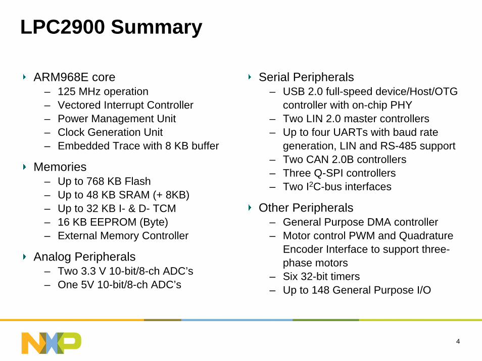
LPC2900 Summary
ARM968E core– 125 MHz operation– Vectored Interrupt Controller– Power Management Unit– Clock Generation Unit– Embedded Trace with 8 KB buffer
Memories– Up to 768 KB Flash– Up to 48 KB SRAM (+ 8KB)– Up to 32 KB I- & D- TCM– 16 KB EEPROM (Byte) – External Memory Controller
Analog Peripherals– Two 3.3 V 10-bit/8-ch ADC’s– One 5V 10-bit/8-ch ADC’s
Serial Peripherals– USB 2.0 full-speed device/Host/OTG
controller with on-chip PHY– Two LIN 2.0 master controllers– Up to four UARTs with baud rate
generation, LIN and RS-485 support– Two CAN 2.0B controllers– Three Q-SPI controllers– Two I2C-bus interfaces
Other Peripherals– General Purpose DMA controller– Motor control PWM and Quadrature
Encoder Interface to support three-phase motors
– Six 32-bit timers– Up to 148 General Purpose I/O

5
LPC2900 Series Details

6
LPC2900 Development Tools
Evaluation Boards Hitex and Keil
AC and DC Motor Control Add On
Compilers/DebuggersKeil, IAR, GreenHills
Code bundles
Hardware DebuggersAll Standard ARM JTAG hardware debuggers work with the LPC2900 devices
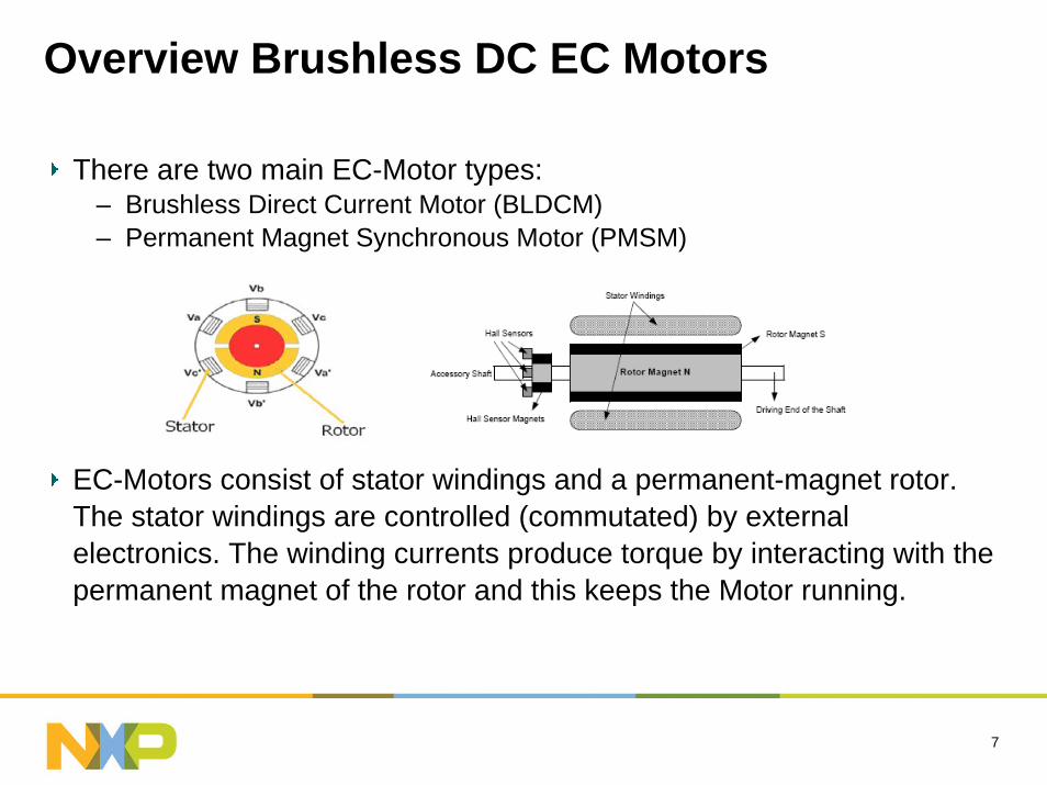
Overview Brushless DC EC Motors
There are two main EC-Motor types:– Brushless Direct Current Motor (BLDCM) – Permanent Magnet Synchronous Motor (PMSM)
EC-Motors consist of stator windings and a permanent-magnet rotor. The stator windings are controlled (commutated) by external electronics. The winding currents produce torque by interacting with the permanent magnet of the rotor and this keeps the Motor running.
7

8
Brushless Motor Commutation
There are two main commutation methods:– Sine-wave – Six-step or block commutation
Sine-wave commutation is used for PMSM
Six Step Commutation is used BLDC Motors– Drives channel current into only two windings at any one time– Use PWM to control drive circuitry

9
Back EMF
The main characteristics of BLDCMs are the square current waveforms and trapezoidal back-EMF.
The amplitude of the current determines the torque of the motor.
In practice switching the supply to the motor with a PWM pattern and adjusting its duty cycle control the effective amplitude

10
BLDCM control
BLDCM control mechanism via commutation point detectionA timer measures the interval between commutation pointsActual speed of motor is calculated P-controller adjusts PWM pulse width to control motor speed
EC-MotorP-Controller=Desired Speed PWM pulse width
Actual revolution time(speed equivalent)

11
Six Step Commutation – Closed Loop control
LPC2900
MSCSS

12
Startup Open Loop - Hard Commutation
When the motor is halted the is no Hall sensor activity (interrupt)
The control must use “hard” commutation for a predefined time.
– Use GPIO – Switch the port function from PWM capture to GPIO
By the appropriate applied commutation a Hall sensor interrupt is generated which makes “hard” commutation unnecessary.
13
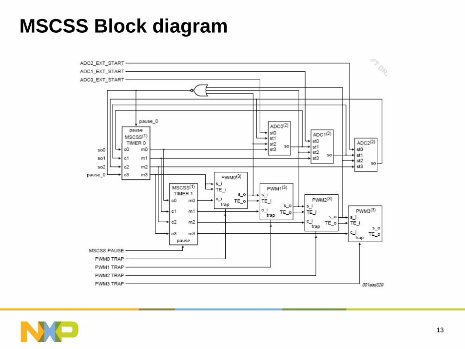
MSCSS Block diagram

14
MSCSS features for Motor Control
The MSCSS provides useful features for motor control applications, making software implementation of motor control algorithms easier:
– Dual edge control– PWM Synchronization delay– ADC compare interrupt– Carrier input of PWM block– Update PWM register through a timer match event
These features off-load the CPU

15
PWM Dual edge and synchronization delay

16
ADC compare interrupt
8 Channel 10bit ADC
Configurable resolution: 2 to 10bit
The ADC compare interrupt is a feature of the ADC.
Interrupt when the conversion result is > or < a predefined threshold.
It reduces the interrupt load as no polling of the ADC result is required.

17
Carrier input of PWM block
This feature allows the PWM to be modulated by the MSCSS Timer
This mechanism is used to generate triangular signals, which represent approximated sine wave signals with little software overhead

18
Update PWM register via Timer match event
Update of PWM register value can be triggered by MSCSS timer 0
Use this feature to update PWM settings
After a preprogrammed time the PWM will be automatically updated
This reduces CPU overhead

19
Hall Sensor
Some motors have integrated Hall sensors for position measurement.
Hall sensors directly indicate the commutation point. The control software has to switch to the next conduction phase on every edge of the sensor output.
Connect to MSCSS PWM Capture inputs for control of motor

20
ADC measurement of Hall sensor output
ADC compare interrupt is used to detect the signal changes of the Hall sensor signals.
Therefore the compare threshold has to be programmed with respect to the conduction state.
With Hall sensors position information is always available even if the motor is standing still.
– Start Use GPIO– Run Use as ADC
The motor starts operation and an ADC compare interrupt is generated when a change on a Hall sensor signal is detected.
21
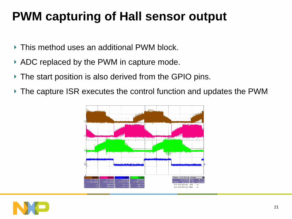
PWM capturing of Hall sensor output
This method uses an additional PWM block.
ADC replaced by the PWM in capture mode.
The start position is also derived from the GPIO pins.
The capture ISR executes the control function and updates the PWM

22
Quadrature Encoder3 signals, Indx, PhA and PhB, for position, direction & speed
Programmable Digital filtering capability
Direction and Position capture
Velocity capture and compare feature
Quadrature Encoder Hall SensorsThree outputs Three outputs
Doesn’t give absolute position Gives absolute positionGives 6 events per electrical
revolutionGives 6 events per electrical
revolution

23
Enhancing performance using TCM
The LPC29xx devices come with up to 32KB of ITCM and DTCM
Using tools like Keil uVision3 simplifies this
ISR Routines in TCM
Frequently called code
Whole application!

24
CPU load of BLDCM (and PMSM)
The CPU load was measured for a motor running at 6000 rpm
For all control algorithms the CPU load was reasonably low.
– BLDCM control the CPU load was only about 1%. – PMSM motor control requires significantly more CPU time (16%).

25
CPU Load Measurements
Block Sine
PWM capturing of Hall sensor output
12.2
3.2+9.5
Flash
8.7
2.3+6.8
ITCM
Position Measurement
Method
ADC measure
of BEMF
ADC measure of Hall sensor
output
PWM capturing
of Hall sensor output
CPU Load 1.4 1.4 1
Time required for
interrupt service +2
[us]
23 22 14.5
Location of application
code Flash Flash Flash

26
LPC29xx DC and AC Motor control Demo
AC and DC motors Examples
PID Controller implementation
Application note detailing implementation
Full board schematics
Complete software (Keil, HiToP + more)
Source code for PC GUI

27
Demonstration of EC Motor Control using the LPC2900

28

29
Additional Product Details

30
LPC290032-bit ARM968E-S processor
State-of-the-Art ARM968E-S industry standard RISC core @ 125 MHz
High performance (1.1MIPS/MHz) with low power consumption
Peripherals connected via multilayer Advanced High-performance Bus (AHB-lite)
NXP Vectored Interrupt Controller (VIC) with 63 sources and 16 priority levels
16-bit THUMB instruction set for increased code density

31
Memories / interfaces
Static RAM– Up to 32KB Tightly Coupled Memory (TCM) for Data and Instruction– 56 KB Total SRAM
• 32 KB general purpose SRAM
• Independent additional 16 KB SRAM
• 8KB of ETB SRAM can be used by CPU
Memory shadowing from Flash to SRAM supported– Enabling faster interrupt execution from SRAM
External Bus Interface for 4 memory banks– 24-bit Address and 32-bit data path – Up to 4 banks with 16MB can be addressed – Data bus configurable as 8-, 16- or 32-bit width– Unused data bus pins become general purpose I/O
32
Tightly coupled memory
Fast memory, local to processor :– High speed performance without system bus (AMBA) access– Smaller die size penalty compared to equivalent amount of cache
Fixed location in memory map
Code and data TCM:– to be initialised before execution– require extra code execution for initialization
Predictable real-time performance (a cache may miss.)
Could be seen as an alternative approach to caches
Can easily be controlled by a small footprint embedded OS– Cache requires a MUCH larger OS to manage it efficiently

33
Fast flash memory
768 KB embedded Flash Memory– 8 small sectors with 8 KB and 11 sectors with 64 KB– Flash security– Robust 2-transistor Flash concept– Self timed programming/erasing preventing over/under-burn/erase– On-chip program/erase generation– Writing in page-mode supported – Flash 128-bit wide interface accelerator enables high speed operation
Programming features– Very fast programming at >2Mb/s, with source code protection features– Initial JTAG Programming and In-Application Programming supported
34
CAN interfaces
2 CAN Controllers– Featuring receive FullCAN mode and Triple Transmit Buffers– Data rates up to 1 Mb/s, CAN 2.0B & ISO 11898 compatible– Error and System Diagnostics Support, Self Reception Mode & Listen Only
Mode– Advanced Hardware Acceptance Filter to reduce CPU load– Certified CAN conformance

35
UART interfaces
2 industry standard 16C550 UARTs– 16 bytes FIFO message buffer for transmit and receive– Receiver FIFO trigger points at
1byte, 4bytes, 8bytes and 14bytes– Register locations conform to 550 industry standard– Built-in baud-rate generator
RS-485 Support
LIN Support

36
SPI & I2C interfaces
3 Full-duplex Queued-Quad SPI (Q-SPI)– Master or slave operation– Supports up to 4 slaves in Sequential Multi Slave operation– Programmable clock bit rate and pre-scale, based on SPI source clock from
the CGU– Max. clock rate in master mode 40MHz, in slave mode 20MHz– Separate transmit and receive FIFO buffers, 16-bit wide, 32 locations deep– Programmable choice of interface operation: Motorola (SPI) or Texas
Instruments (SSI)– Programmable data frame size from 4 to 16 bits– Internal loop back test mode
2 I2C buses– 400 KHz transfer rates– Supports monitor mode– Supports multiple address recognition from one port.

37
Fast A/D Converter
Two 3.3V A/D Converters – 8 channels each– Configurable resolution: 10-bit ..2-bit– High accuracy: ±1LSB (±5mV, full scale ±20mV)– 400k samples/s at 10bit resolution,
1.500k samples/s at 2bit resolution– Conversion time ≤ 2.5 µs per channel– Automatic scan mode
• Single or continuous, with interrupt at end of scan – Internal & external trigger start options– Zero-crossing detection
• Programmable reference level with an interrupt to CPU
5V A/D Converter– 8 channels
38
PWM Module
4 PWM modules– Each module with 6 channels– Configurable resolution: 16-bit ..2-bit (plus a 16-bit pre-scaler)– Frequency range up to 58kHz (at 10bit) – Double edge PWM generation
• 3 capture/compare inputs – Support brushless DC motor
• Burst mode (e.g. 50kHz modulation) to reduce switching current
• Trap input signal

39
Timers
Watchdog Timer, with timer change protection– Internal chip reset when not triggered periodically– Debug mode with interrupt instead of reset– By default enabled with fixed time-out for watchdog configuring– Watchdog time period change protected with access sequence
4 x 32-bit Counter/Timers with programmable 32-bit prescalers– Up to four 32-bit Match Registers per counter/timer– Up to four 32-bit Capture Channels per counter/timer– External Capture and Match I/O supported
40
MiscellaneousDual power supply
– CPU operating at 1.8V ± 5%– I/O operating at 2.7V to 3.6V, 5V tolerant
LQFP100/144/208 packages
Multiplexed outputs, unused pins become general purpose I/O pins
Boundary scan test supported via JTAG interface
Operating temperature range -40 to +85 degree C

41

Basic EC-Motor Control SystemLPC2900 MSCSS is used to control the motor power stage.
Six Pulse Width Modulation (PWM) signals are fed to the power stage to control the six MOSFETs of the 3-phase inverter circuit.
3-phase Inverters consist of two half bridges for each motor phase. These half bridges consist of two power MOSFETs or IGBTs
LPC2900
MSCSS
42

43
Sensorless Control
R1R1
R1
R2
R2
R2
R3R3
R3
Motor Phase
Motor Phase
Motor Phase
Virtual Starpoint
ADCCH2
CH1
CH3 CH4

44
Back EMF
The zero crossing point of the BEMF doesn’t directly indicate the commutation point because it is in the middle of one conduction phase
Therefore the half of the commutation time has to be advanced until the phase supply voltages can be changed.
BEMF
Current
+
+
-
-

45
RPM Measurement
The RPM can be calculated by determining the period between two rising or falling edges of one Hall sensor through the captured value in the sensor related capture register.
With the number of ticks between those events, the PWM base clock, and the PWM prescale value the speed can be calculated easily by using the following formula:
RPM = ((PWM CLOCK/(PWM Prescaler+1))*60.0)/(CaptureValue));
For a higher precision the period between n rising edges is used to calculate the speed in this application, whereas n stands for the number of poles

46