Embed Size (px)
Citation preview

OBJECTIVES
Upon completion of this chapter, you will be able to:
>> >> Describe the basic operation of a relay>> >> Interface the PIC18 with a relay>> >> Describe the basic operation of an optoisolator>> >> Interface the PIC18 with an optoisolator>> >> Describe the basic operation of a stepper motor>> >> Interface the PIC18 with a stepper motor>> >> Code PIC18 programs to control and operate a stepper motor>> >> Define stepper motor operation in terms of step angle, steps
per revolution, tooth pitch, rotation speed, and RPM>> >> Describe the basic operation of a DC motor>> >> Interface the PIC18 with a DC motor>> >> Code PIC18 programs to control and operate a DC motor>> >> Describe how PWM is used to control motor speed>> >> Code CCP programs to control and operate a DC motor>> >> Code ECCP programs to control and operate a DC motor
CHAPTER 17
MOTOR CONTROL:RELAY, PWM, DC, AND
STEPPER MOTORS
635

This chapter discusses motor control and shows PIC18 interfacing withrelays, optoisolators, stepper motors, and DC motors. In Section 17.1, the basicsof relays and optoisolators are described. Then we show their interfacing with thePIC18. In Section 17.2, stepper motor interfacing with the PIC18 is shown. Thecharacteristics of DC motors are discussed in Section 17.3, along with their inter-facing to the PIC18. We will also discuss the topic of PWM (pulse width modula-tion). In Section 17.4, the CCP feature of PIC18 is used to control DC motors,while the ECCP usage in motor control is shown in Section 17.5. We use bothAssembly and C in our programming examples.
SECTION 17.1: RELAYS AND OPTOISOLATORS
This section begins with an overview of the basic operations of electro-mechanical relays, solid-state relays, reed switches, and optoisolators. Then wedescribe how to interface them to the PIC18. We use both Assembly and C lan-guage programs to demonstrate their control.
Electromechanical relaysA relay is an electrically controllable switch widely used in industrial con-
trols, automobiles, and appliances. It allows the isolation of two separate sectionsof a system with two different voltage sources. For example, a +5 V system can beisolated from a 120 V system by placing a relay between them. One such relay iscalled an electromechanical (or electromagnetic) relay (EMR) as shown in Figure17-1. The EMRs have three components: the coil, spring, and contacts. In Figure17-1, a digital +5 V on the left side can control a 12 V motor on the right side with-out any physical contact between them. When current flows through the coil, amagnetic field is created around the coil (the coil is energized), which causes thearmature to be attracted to the coil. The armature's contact acts like a switch andcloses or opens the circuit. When the coil is not energized, a spring pulls the arma-ture to its normal state of open or closed. In the block diagram for electomechan-ical relays (EMR) we do not show the spring, but it does exist internally. There areall types of relays for all kinds of applications. In choosing a relay the followingcharacteristics need to be considered:
1. The contacts can be normally open (NO) or normally closed (NC). In the NCtype, the contacts are closed when the coil is not energized. In the NO, the con-tacts are open when the coil is unenergized.
2. There can one or more contacts. For example, we can have SPST (single pole,single throw), SPDT (single pole, double throw), and DPDT (double pole, dou-ble throw) relays.
3. The voltage and current needed to energize the coil. The voltage can vary froma few volts to 50 volts, while the current can be from a few mA to 20 mA. Therelay has a minimum voltage, below which the coil will not be energized. Thisminimum voltage is called the “pull-in” voltage. In the datasheet for relays wemight not see current, but rather coil resistance. The V/R will give you the pull-in current. For example, if the coil voltage is 5 V, and the coil resistance is 500ohms, we need a minimum of 10 mA (5 V/500 ohms = 10 mA) pull-in current.
636

4. The maximum DC/AC voltage and current that can be handled by the contacts.This is in the range of a few volts to hundreds of volts, while the current canbe from a few amps to 40 A or more, depending on the relay. Notice the dif-ference between this voltage/current specification and the voltage/currentneeded for energizing the coil. The fact that one can use such a small amountof voltage/current on one side to handle a large amount of voltage/current onthe other side is what makes relays so widely used in industrial controls.Examine Table 17-1 for some relay characteristics.
CHAPTER 17: MOTOR CONTROL: RELAY, PWM, DC, AND STEPPER MOTORS 637
Table 17-1: Selected DIP Relay Characteristics (www.Jameco.com)
Part No. Contact Form Coil Volts Coil Ohms Contact Volts-Current106462CP SPST-NO 5 VDC 500 100 VDC-0.5 A138430CP SPST-NO 5 VDC 500 100 VDC-0.5 A106471CP SPST-NO 12 VDC 1000 100 VDC-0.5 A138448CP SPST-NO 12 VDC 1000 100 VDC-0.5 A129875CP DPDT 5 VDC 62.5 30 VDC-1 A
Common
Normally Open
Common
Normally Open
Normally Closed
Common
Normally Open
Normally Closed
Figure 17-1. Relay Diagrams
(c) DPDT
(b) SPDT(a) SPST
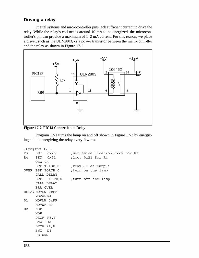
Driving a relayDigital systems and microcontroller pins lack sufficient current to drive the
relay. While the relay’s coil needs around 10 mA to be energized, the microcon-troller's pin can provide a maximum of 1–2 mA current. For this reason, we placea driver, such as the ULN2803, or a power transistor between the microcontrollerand the relay as shown in Figure 17-2.
Program 17-1 turns the lamp on and off shown in Figure 17-2 by energiz-ing and de-energizing the relay every few ms.
;Program 17-1R3 SET 0x20 ;set aside location 0x20 for R3R4 SET 0x21 ;loc. 0x21 for R4
ORG 0HBCF TRISB,0 ;PORTB.0 as output
OVER BSF PORTB,0 ;turn on the lamp CALL DELAYBCF PORTB,0 ;turn off the lampCALL DELAYBRA OVER
DELAY MOVLW 0xFFMOVWF R4
D1 MOVLW 0xFFMOVWF R3
D2 NOPNOPDECF R3,FBNZ D2DECF R4,FBNZ D1RETURN
638
+12V+5V
1 18
9
ULN2803DS89C4x0106462
2
6
14
8P1.0
+5V
10
4.7k
+5V
Figure 17-2. PIC18 Connection to Relay
PIC18F
RB0

Solid-state relayAnother widely used relay is the solid-state relay. See Table 17-2. In this
relay, there is no coil, spring, or mechanical contact switch. The entire relay ismade out of semiconductor materials. Because no mechanical parts are involvedin solid-state relays, their switching response time is much faster than that ofelectromechanical relays. Another advantage of the solid-state relay is its greaterlife expectancy. The life cycle for the electromechanical relay can vary from a fewhundred thousand to a few million operations. Wear and tear on the contact pointscan cause the relay to malfunction after a while. Solid-state relays, however, haveno such limitations. Extremely low input current and small packaging make solid-state relays ideal for microprocessor and logic control switching. They are widelyused in controlling pumps, solenoids, alarms, and other power applications. Somesolid-state relays have a phase control option, which is ideal for motor-speed con-trol and light-dimming applications. Figure 17-3 shows control of a fan using asolid-state relay (SSR).
CHAPTER 17: MOTOR CONTROL: RELAY, PWM, DC, AND STEPPER MOTORS 639
Table 17-2: Selected Solid-State Relay Characteristics (www.Jameco.com)
Part No. Contact Style Control Volts Contact Volts Contact Current143058CP SPST 4–32 VDC 240 VAC 3 A139053CP SPST 3–32 VDC 240 VAC 25 A162341CP SPST 3–32 VDC 240 VAC 10 A172591CP SPST 3–32 VDC 60 VDC 2 A175222CP SPST 3–32 VDC 60 VDC 4 A176647CP SPST 3–32 VDC 120 VDC 5 A
4
13
1623418051
P1.02
120VAC
FANZERO
VOLTAGECIRCUIT
+5
Figure 17-3. PIC18 Connection to a Solid-State Relay
PIC18F
RB0
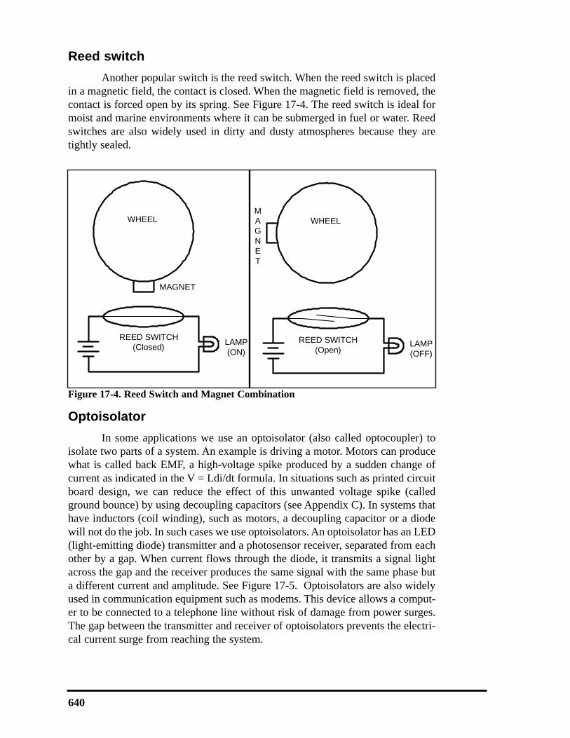
Reed switchAnother popular switch is the reed switch. When the reed switch is placed
in a magnetic field, the contact is closed. When the magnetic field is removed, thecontact is forced open by its spring. See Figure 17-4. The reed switch is ideal formoist and marine environments where it can be submerged in fuel or water. Reedswitches are also widely used in dirty and dusty atmospheres because they aretightly sealed.
OptoisolatorIn some applications we use an optoisolator (also called optocoupler) to
isolate two parts of a system. An example is driving a motor. Motors can producewhat is called back EMF, a high-voltage spike produced by a sudden change ofcurrent as indicated in the V = Ldi/dt formula. In situations such as printed circuitboard design, we can reduce the effect of this unwanted voltage spike (calledground bounce) by using decoupling capacitors (see Appendix C). In systems thathave inductors (coil winding), such as motors, a decoupling capacitor or a diodewill not do the job. In such cases we use optoisolators. An optoisolator has an LED(light-emitting diode) transmitter and a photosensor receiver, separated from eachother by a gap. When current flows through the diode, it transmits a signal lightacross the gap and the receiver produces the same signal with the same phase buta different current and amplitude. See Figure 17-5. Optoisolators are also widelyused in communication equipment such as modems. This device allows a comput-er to be connected to a telephone line without risk of damage from power surges.The gap between the transmitter and receiver of optoisolators prevents the electri-cal current surge from reaching the system.
640
WHEEL
MAGNET
LAMP(ON)
REED SWITCH(Closed)
WHEELMAGNET
LAMP(OFF)
REED SWITCH(Open)
Figure 17-4. Reed Switch and Magnet Combination

Interfacing an optoisolatorThe optoisolator comes in a small IC package with four or more pins.
There are also packages that contain more than one optoisolator. When placing anoptoisolator between two circuits, we must use two separate voltage sources, onefor each side, as shown in Figure 17-6. Unlike relays, no drivers need to be placedbetween the microcontroller/digital output and the optoisolators.
CHAPTER 17: MOTOR CONTROL: RELAY, PWM, DC, AND STEPPER MOTORS 641
1
2
3
4
8
7
6
5
LAMP
+12V
+5V
330
P1.0
8051ILD74
OPTOISOLATOR
Figure 17-6. Controlling a Lamp via an Optoisolator
Figure 17-5. Optoisolator Package Examples
1
2
5
6
16
15
12
11
ILQ74OPTOISOLATOR
4
7
8
13
10
9
3 14
1
2
3
4
8
7
6
5
ILD74OPTOISOLATOR
1
2
3
6
5
4
IL74OPTOISOLATOR
PIC18F
RB0

Review Questions1. Give one application where would you use a relay.2. Why do we place a driver between the microcontroller and the relay?3. What is an NC relay?4. Why are relays that use coils called electromechanical relays?5. What is the advantage of a solid-state relay over EMR?6. What is the advantage of an optoisolator over an EM relay?
SECTION 17.2: STEPPER MOTOR INTERFACING
This section begins with an overview of the basic operation of steppermotors. Then we describehow to interface a steppermotor to the PIC18. Finally,we use Assembly languageprograms to demonstrate con-trol of the angle and directionof stepper motor rotation.
Stepper motorsA stepper motor is a
widely used device that trans-lates electrical pulses intomechanical movement. Inapplications such as diskdrives, dot matrix printers,and robotics, the steppermotor is used for positioncontrol. Stepper motors com-monly have a permanent mag-net rotor (also called theshaft) surrounded by a stator(see Figure 17-7). There arealso steppers called variablereluctance stepper motors thatdo not have a permanent mag-net rotor. The most commonstepper motors have four sta-tor windings that are pairedwith a center-tapped commonas shown in Figure 17-8. Thistype of stepper motor is com-monly referred to as a four-phase or unipolar steppermotor. The center tap allows achange of current direction in
642
N
N
S
S
S
N
A
B
C D
N
NS
S
S
N
A
B
C D
AverageNorth
AverageSouth
Figure 17-7. Rotor Alignment
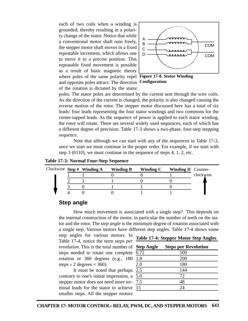
each of two coils when a winding isgrounded, thereby resulting in a polari-ty change of the stator. Notice that whilea conventional motor shaft runs freely,the stepper motor shaft moves in a fixedrepeatable increment, which allows oneto move it to a precise position. Thisrepeatable fixed movement is possibleas a result of basic magnetic theorywhere poles of the same polarity repeland opposite poles attract. The directionof the rotation is dictated by the statorpoles. The stator poles are determined by the current sent through the wire coils.As the direction of the current is changed, the polarity is also changed causing thereverse motion of the rotor. The stepper motor discussed here has a total of sixleads: four leads representing the four stator windings and two commons for thecenter-tapped leads. As the sequence of power is applied to each stator winding,the rotor will rotate. There are several widely used sequences, each of which hasa different degree of precision. Table 17-3 shows a two-phase, four-step steppingsequence.
Note that although we can start with any of the sequences in Table 17-3,once we start we must continue in the proper order. For example, if we start withstep 3 (0110), we must continue in the sequence of steps 4, 1, 2, etc.
Step angleHow much movement is associated with a single step? This depends on
the internal construction of the motor, in particular the number of teeth on the sta-tor and the rotor. The step angle is the minimum degree of rotation associated witha single step. Various motors have different step angles. Table 17-4 shows somestep angles for various motors. InTable 17-4, notice the term steps perrevolution. This is the total number ofsteps needed to rotate one completerotation or 360 degrees (e.g., 180steps × 2 degrees = 360).
It must be noted that perhapscontrary to one's initial impression, astepper motor does not need more ter-minal leads for the stator to achievesmaller steps. All the stepper motors
CHAPTER 17: MOTOR CONTROL: RELAY, PWM, DC, AND STEPPER MOTORS 643
COM
COM
ABCD
Figure 17-8. Stator WindingConfiguration
Table 17-4: Stepper Motor Step Angles
Step Angle Steps per Revolution0.72 5001.8 2002.0 1802.5 1445.0 727.5 4815 24
Table 17-3: Normal Four-Step Sequence
Counter-clockwise
Step # Winding A Winding B Winding C Winding D1 1 0 0 12 1 1 0 03 0 1 1 04 0 0 1 1
Clockwise

discussed in this section have four leads for the stator winding and two COM wiresfor the center tap. Although some manufacturers set aside only one lead for thecommon signal instead of two, they always have four leads for the stators. SeeExample 17-1. Next we discuss some associated terminology in order to under-stand the stepper motor further.
644
Describe the PIC18 connection to the stepper motor of Figure 17-9 and code a programto rotate it continuously.
Solution:
The following steps show the PIC18 connection to the stepper motor and its program-ming:
1. Use an ohmmeter to measure the resistance of the leads. This should identify whichCOM leads are connected to which winding leads.
2. The common wire(s) are connected to the positive side of the motor's power supply.In many motors, +5 V is sufficient.
3. The four leads of the stator winding are controlled by four bits of the PIC18 port(RB0–RB3). Because the PIC18 lacks sufficient current to drive the stepper motorwindings, we must use a driver such as the ULN2003 to energize the stator. Insteadof the ULN2003, we could have used transistors as drivers, as shown in Figure17-11. However, notice that if transistors are used as drivers, we must also usediodes to take care of inductive current generated when the coil is turned off. Onereason that using the ULN2003 is preferable to the use of transistors as drivers isthat the ULN2003 has an internal diode to take care of back EMF.
MyReg SET 0x30 ;loc 30H for MyRegR2 SET 0x20 ;loc 20H for R2 Reg
CLRF TRISB ;Port B as outputMOVLW 0x66 ;load step sequenceMOVWF MyReg
BACK MOVFF MyReg,PORTB ;issue sequence to motorRRNCF MyReg,F ;rotate right clockwiseCALL DELAY ;waitBRA BACK ;keep going
DELAYMOVLW 0xFFMOVWF R2
D1 NOPDECF R2,FBNZ D1RETURNEND
Change the value of DELAY to set the speed of rotation.We can use the single-bit instructions BSF and BCF instead of RRNCF to create thesequences.
Example 17-1

Steps per second and rpm relation The relation between rpm (revolutions per minute), steps per revolution,
and steps per second is as follows.
The 4-step sequence and number of teeth on rotor The switching sequence shown earlier in Table 17-3 is called the 4-step
switching sequence because after four steps the same two windings will be "ON".How much movement is associated with these four steps? After completing everyfour steps, the rotor moves only one tooth pitch. Therefore, in a stepper motor with200 steps per revolution, the rotor has 50 teeth because 4 × 50 = 200 steps are need-ed to complete one revolution. This leads to the conclusion that the minimum stepangle is always a function of the number of teeth on the rotor. In other words, thesmaller the step angle, the more teeth the rotor passes. See Example 17-2.
CHAPTER 17: MOTOR CONTROL: RELAY, PWM, DC, AND STEPPER MOTORS 645
Steps per second = rpm × Steps per revolution60
Give the number of times the four-step sequence in Table 17-3 must be applied to a stepper motor to make an 80-degree move if the motor has a 2-degree step angle.
Solution:A motor with a 2-degree step angle has the following characteristics:Step angle: 2 degrees Steps per revolution: 180Number of rotor teeth: 45 Movement per 4-step sequence: 8 degreesTo move the rotor 80 degrees, we need to send 10 consecutive 4-step sequences,because 10 × 4 steps × 2 degrees = 80 degrees.
Example 17-2
Figure 17-9. PIC18 Connection to Stepper Motor
DS89C4x0
P1.0
P1.1
P1.2
P1.3
+5
9
Use one power supply for the motor and ULN2003 and another for the 8051
8
ULN20034.7k 4.7k 4.7k 4.7k
+5
+5
Unipolar Stepper Motor
To stepper motor supply
PIC18F
RB0RB1
RB2RB3

Looking at Example 17-2, one might wonder what happens if we want tomove 45 degrees, because the steps are 2 degrees each. To allow for finer resolu-tions, all stepper motors allow what is called an 8-step switching sequence. The 8-step sequence is also called half-stepping, because in the 8-step sequence each stepis half of the normal step angle. For example, a motor with a 2-degree step anglecan be used as a 1-degree step angle if the sequence of Table 17-5 is applied.
Motor speedThe motor speed, measured in steps per second (steps/s), is a function of
the switching rate. Notice in Example 17-1 that by changing the length of the timedelay loop, we can achieve various rotation speeds.
Holding torqueThe following is a definition of holding torque: “With the motor shaft at
standstill or zero rpm condition, the amount of torque, from an external source,required to break away the shaft from its holding position. This is measured withrated voltage and current applied to the motor.” The unit of torque is ounce-inch(or kg-cm).
Wave drive 4-step sequenceIn addition to the 8-step and the 4-step sequences discussed earlier, there is
another sequence called the wave drive 4-step sequence. It is shown in Table 17-6.Notice that the 8-step sequence of Table 17-5 is simply the combination of thewave drive 4-step and normal 4-step normal sequences shown in Tables 17-6 and17-3, respectively. Experimenting with the wave drive 4-step sequence is left tothe reader.
646
Table 17-6: Wave Drive 4-Step SequenceStep # Winding A Winding B Winding C Winding D1 1 0 0 02 0 1 0 03 0 0 1 04 0 0 0 1
Clockwise Counter-clockwise
Table 17-5: Half-Step 8-Step SequenceStep # Winding A Winding B Winding C Winding D1 1 0 0 12 1 0 0 03 1 1 0 04 0 1 0 05 0 1 1 06 0 0 1 07 0 0 1 18 0 0 0 1
Clockwise Counter-clockwise

Unipolar versus bipolar stepper motor interfaceThere are three common types of stepper motor interfacing: universal,
unipolar, and bipolar. They can be identified by the number of connections to themotor. A universal stepper motor has eight, while the unipolar has six and the bipo-lar has four. The universal stepper motor can be configured for all three modes,while the unipolar can be either unipolar or bipolar. Obviously the bipolar cannotbe configured for universal nor unipolar mode. Table 17-7 shows selected steppermotor characteristics. Figure 17-10 shows the basic internal connections of allthree type of configurations.
Unipolar stepper motors can be controlled using the basic interfacingshown in Figure 17-11, whereas the bipolar stepper requires H-Bridge circuitry.Bipolar stepper motors require a higher operational current than the unipolar; theadvantage of this is a higher holding torque.
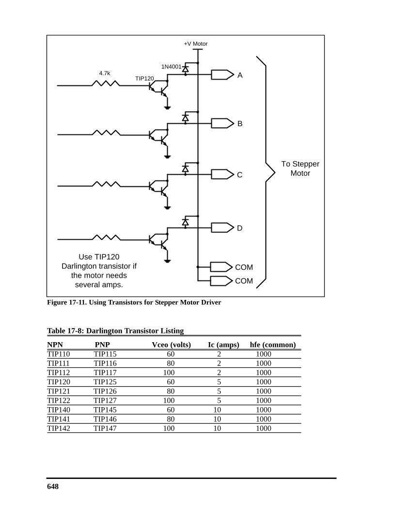
Using transistors as driversFigure 17-11 shows an interface to a unipolar stepper motor using transis-
tors. Diodes are used to reduce the back EMF spike created when the coils areenergized and de-energized, similar to the electromechanical relays discussed ear-lier. TIP transistors can be used to supply higher current to the motor. Table 17-8lists the common industrial Darlington transistors. These transistors can accom-modate higher voltages and currents.
CHAPTER 17: MOTOR CONTROL: RELAY, PWM, DC, AND STEPPER MOTORS 647
Table 17-7: Selected Stepper Motor Characteristics (www.Jameco.com)
Part No. Step Angle Drive System Volts Phase Resistance Current 151861CP 7.5 unipolar 5 V 9 ohms 550 mA171601CP 3.6 unipolar 7 V 20 ohms 350 mA164056CP 7.5 bipolar 5 V 6 ohms 800 mA
(a) Universal (b) Unipolar (c) Bipolar
Figure 17-10. Common Stepper Motor Types
648
Figure 17-11. Using Transistors for Stepper Motor Driver
TIP120
+V Motor
A
B
C
D
1N4001
COM
COM
Use TIP120 Darlington transistor if
the motor needs several amps.
To Stepper Motor
4.7k
Table 17-8: Darlington Transistor Listing
NPN PNP Vceo (volts) Ic (amps) hfe (common)TIP110 TIP115 60 2 1000TIP111 TIP116 80 2 1000TIP112 TIP117 100 2 1000TIP120 TIP125 60 5 1000TIP121 TIP126 80 5 1000TIP122 TIP127 100 5 1000TIP140 TIP145 60 10 1000TIP141 TIP146 80 10 1000TIP142 TIP147 100 10 1000

Controlling stepper motor via optoisolatorIn the first section of this chapter we examined the optoisolator and its use.
Optoisolators are widely used to isolate the stepper motor’s EMF voltage and keepit from damaging the digital/microcontroller system. This is shown in Figure17-12. See Examples 17-3 and 17-4.
CHAPTER 17: MOTOR CONTROL: RELAY, PWM, DC, AND STEPPER MOTORS 649
Figure 17-12. Controlling Stepper Motor via Optoisolator
8051
P1.0
P1.1
P1.2
P1.3
+12
10
Use one power supply for the motor and ULN2003
and another for the 8051.
9
ULN2803
1k
+12
+12
Unipolar Stepper Motor
ILQ74 Opto
470 470 470 470
+5
12346587
16
151413
1112
910
The optoisolator provides additional protection of the
8051.
1k
1k
1k
A switch is connected to pin RD7 (PORTD.7). Write a program to monitor the status ofSW and perform the following:(a) If SW = 0, the stepper motor moves clockwise.(b) If SW = 1, the stepper motor moves counterclockwise.
Solution:
MyReg SET 0x30 ;loc 30H for MyRegBSF TRISD,RD7 ;RD7 as input pinCLRF TRISB ;Port B as outputMOVLW 0x66 ;load step sequenceMOVWF MyReg
BACK BTFSS PORTD,RD7 ;check the SWBRA OVER ;It is high. Make it clockwiseMOVFF MyReg,PORTB ;issue sequence to motorRRNCF MyReg,F ;rotate right clockwiseCALL DELAY ;waitBRA BACK ;keep going
OVER MOVFF MyReg,PORTB ;issue sequence to motorRLNCF MyReg,F ;rotate left clockwiseCALL DELAY ;waitBRA BACK ;keep going
Example 17-3
PIC18F
RB0RB1RB2RB3

Stepper motor control with PIC18 CThe PIC18 C version of the stepper motor control is given below. In this
program we could have used << (shift left) and >> (shift right) as was shown inChapter 7.
#include <p18f458.h>void main()
{TRISB=0x0; //PORTB as outputwhile(1)
{PORTB = 0x66;MSDelay(100);PORTB = 0xCC;MSDelay(100);PORTB = 0x99;MSDelay(100);PORTB = 0x33;MSDelay(100);
}}
650
A switch is connected to pin RD7. Write a C program to monitor the status of SW andperform the following:(a) If SW = 0, the stepper motor moves clockwise.(b) If SW = 1, the stepper motor moves counterclockwise.
Solution:
#include <p18f458.h>#define SW PORTDbits.RD7void MSDelay(int ms);void main()
{TRISD=0x80; //RD7 as input pinTRISB=0x0; //PORTB as outputwhile(1)
{if(SW == 0)
{PORTB = 0x66;MSDelay(100);PORTB = 0xCC;MSDelay(100);PORTB = 0x99;MSDelay(100);PORTB = 0x33;MSDelay(100);}
else{PORTB = 0x66;MSDelay(100);PORTB = 0x33;
Example 17-4
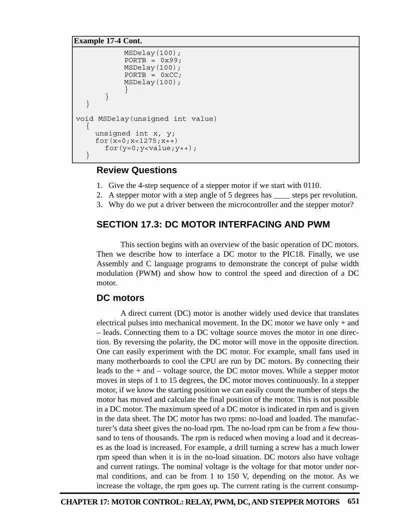
Review Questions1. Give the 4-step sequence of a stepper motor if we start with 0110.2. A stepper motor with a step angle of 5 degrees has ____ steps per revolution.3. Why do we put a driver between the microcontroller and the stepper motor?
SECTION 17.3: DC MOTOR INTERFACING AND PWM
This section begins with an overview of the basic operation of DC motors.Then we describe how to interface a DC motor to the PIC18. Finally, we useAssembly and C language programs to demonstrate the concept of pulse widthmodulation (PWM) and show how to control the speed and direction of a DCmotor.
DC motorsA direct current (DC) motor is another widely used device that translates
electrical pulses into mechanical movement. In the DC motor we have only + and– leads. Connecting them to a DC voltage source moves the motor in one direc-tion. By reversing the polarity, the DC motor will move in the opposite direction.One can easily experiment with the DC motor. For example, small fans used inmany motherboards to cool the CPU are run by DC motors. By connecting theirleads to the + and – voltage source, the DC motor moves. While a stepper motormoves in steps of 1 to 15 degrees, the DC motor moves continuously. In a steppermotor, if we know the starting position we can easily count the number of steps themotor has moved and calculate the final position of the motor. This is not possiblein a DC motor. The maximum speed of a DC motor is indicated in rpm and is givenin the data sheet. The DC motor has two rpms: no-load and loaded. The manufac-turer’s data sheet gives the no-load rpm. The no-load rpm can be from a few thou-sand to tens of thousands. The rpm is reduced when moving a load and it decreas-es as the load is increased. For example, a drill turning a screw has a much lowerrpm speed than when it is in the no-load situation. DC motors also have voltageand current ratings. The nominal voltage is the voltage for that motor under nor-mal conditions, and can be from 1 to 150 V, depending on the motor. As weincrease the voltage, the rpm goes up. The current rating is the current consump-
CHAPTER 17: MOTOR CONTROL: RELAY, PWM, DC, AND STEPPER MOTORS 651
MSDelay(100);PORTB = 0x99;MSDelay(100);PORTB = 0xCC;MSDelay(100);}
}}
void MSDelay(unsigned int value){
unsigned int x, y;for(x=0;x<1275;x++)
for(y=0;y<value;y++);}
Example 17-4 Cont.

tion when the nominal voltage is applied with no load, and can be from 25 mA toa few amps. As the load increases, the rpm is decreased, unless the current or volt-age provided to the motor is increased, which in turn increases the torque. With afixed voltage, as the load increases, the current (power) consumption of a DCmotor is increased. If we overload the motor it will stall, and that can damage themotor due to the heat generated by high current consumption.
Unidirectional controlFigure 17-13 shows the DC motor rotation for clockwise (CW) and coun-
terclockwise (CCW) rotations. See Table 17-9 for selected DC motors.
Bidirectional controlWith the help of relays or some specially designed chips we can change the
direction of the DC motor rotation. Figures 17-14 through 17-17 show the basicconcepts of H-Bridge control of DC motors.
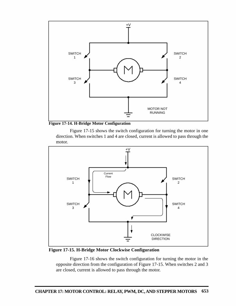
Figure 17-14 shows the connection of an H-Bridge using simple switches.All the switches are open, which does not allow the motor to turn.
652
MOTOR
Clockwise Rotation
MOTOR
Counter-Clockwise Rotation
Figure 17-13. DC Motor Rotation (Permanent Magnet Field)
Table 17-9: Selected DC Motor Characteristics (www.Jameco.com)
Part No. Nominal Volts Volt Range Current RPM Torque154915CP 3 V 1.5–3 V 0.070 A 5,200 4.0 g-cm154923CP 3 V 1.5–3 V 0.240 A 16,000 8.3 g-cm177498CP 4.5 V 3–14 V 0.150 A 10,300 33.3 g-cm181411CP 5 V 3–14 V 0.470 A 10,000 18.8 g-cm
CHAPTER 17: MOTOR CONTROL: RELAY, PWM, DC, AND STEPPER MOTORS 653
Figure 17-15 shows the switch configuration for turning the motor in onedirection. When switches 1 and 4 are closed, current is allowed to pass through themotor.
Figure 17-16 shows the switch configuration for turning the motor in theopposite direction from the configuration of Figure 17-15. When switches 2 and 3are closed, current is allowed to pass through the motor.
+V
MOTOR NOT RUNNING
SWITCH1
SWITCH2
SWITCH3
SWITCH4
Figure 17-14. H-Bridge Motor Configuration
+V
CLOCKWISE DIRECTION
SWITCH1
SWITCH2
SWITCH3
SWITCH4
Current Flow
Figure 17-15. H-Bridge Motor Clockwise Configuration

Figure 17-17 shows an invalid configuration. Current flows directly toground, creating a short circuit. The same effect occurs when switches 1 and 3 areclosed or switches 2 and 4 are closed.
Table 17-10 shows some of the logic configurations for the H-Bridgedesign.
H-Bridge control can be created using relays, transistors, or a single ICsolution such as the L293. When using relays and transistors, you must ensure thatinvalid configurations do not occur.
654
+V
COUNTER CLOCKWISE DIRECTION
SWITCH1
SWITCH2
SWITCH3
SWITCH4
Current Flow
Figure 17-16. H-Bridge Motor Counterclockwise Configuration
+V
INVALID STATE(SHORT CIRCUIT)
SWITCH1
SWITCH2
SWITCH3
SWITCH4
Figure 17-17. H-Bridge in an Invalid Configuration

CHAPTER 17: MOTOR CONTROL: RELAY, PWM, DC, AND STEPPER MOTORS 655
Although we do not show the relay control of an H-Bridge, Example 17-5shows a simple program to operate a basic H-Bridge.
See http://www.MicroDigitalEd.com for additional information on usingH-Bridges.
Figure 17-18 shows the connection of the L293 to an PIC18. Be aware thatthe L293 will generate heat during operation. For sustained operation of the motor,use a heat sink. Example 17-6 shows control of the L293.
A switch is connected to pin RD7 (PORTD.7). Using a simulator, write a program tosimulate the H-Bridge in Table 17-10. We must perform the following:(a) If DIR = 0, the DC motor moves clockwise.(b) If DIR = 1, the DC motor moves counterclockwise.
Solution:
BCF TRISB,0 ;PORTB.0 as output for switch 1BCF TRISB,1 ; .1 ” switch 2BCF TRISB,2 ; .2 ” switch 3BCF TRISB,3 ; .3 ” switch 4BSF TRISD,7 ;make PORTD.7 an input DIR
MONITOR:BTFSS PORTD,7BRA CLOCKWISEBSF PORTB,0 ;switch 1BCF PORTB,1 ;switch 2BCF PORTB,2 ;switch 3BSF PORTB,3 ;switch 4BRA MONITOR
CLOCKWISE:BCF PORTB,0 ;switch 1BSF PORTB,1 ;switch 2BSF PORTB,2 ;switch 3BCF PORTB,3 ;switch 4BRA MONITOR
View the results on your simulator. This example is for simulation onlyand should not be used on a connected system.
Example 17-5
Table 17-10: Some H-Bridge Logic Configurations for Figure 17-14
Motor Operation SW1 SW2 SW3 SW4Off Open Open Open OpenClockwise Closed Open Open ClosedCounterclockwise Open Closed Closed OpenInvalid Closed Closed Closed Closed

656
+12V
8
6
3
4, 5, 12, 13
L293
OUTPUT 1
OUTPUT 2
GND
VCC2
INPUT 1
INPUT 2
ENABLE
VCC116
2
7
1
+12V
D1
D3
D2
D4
D1, D2, D3, D4 are 1N4004
8051
P1.0
P1.1
P1.2
1k
+12ILQ74 Opto
470 470 470
+5
12
3
4
6
5
16
151413
1112
The optoisolator provides additional protection of the
8051
1k
1k
Use a separate power supply for the motor and L293 than for the 8051
Figure 17-18. Bidirectional Motor Control Using an L293 Chip
Figure 17-18 shows the connection of an L293. Add a switch to pin RD7 (PORTD.7).Write a program to monitor the status of SW and perform the following:
(a) If SW = 0, the DC motor moves clockwise.(b) If SW = 1, the DC motor moves counterclockwise.
Solution:
BCF TRISB,0BCF TRISB,1BCF TRISB,2BSF TRISD,7BSF PORTB,0 ;enable the chip
CHK BTFSS PORTD,7BRA CWISEBCF PORTB,1 ;turn the motor counterclockwiseBSF PORTB,2BRA CHK
CWISE BSF PORTB,1BCF PORTB,2 ;turn motor clockwiseBRA CHK
Example 17-6
RB0
RB1
RB2
PIC18F
PIC18F
PIC18F

Pulse width modulation (PWM)The speed of the motor depends on three factors: (a) load, (b) voltage, and
(c) current. For a given fixed load we can maintain a steady speed by using amethod called pulse width modulation (PWM). By changing (modulating) thewidth of the pulse applied to the DC motor we can increase or decrease the amountof power provided to the motor, thereby increasing or decreasing the motor speed.Notice that, although the voltage has a fixed amplitude, it has a variable duty cycle.That means the wider the pulse, the higher the speed. PWM is so widely used inDC motor control that some microcontrollers come with the PWM circuitryembedded in the chip. In such microcontrollers all we have to do is load the prop-er registers with the values of the high and low portions of the desired pulse, andthe rest is taken care of by the microcontroller. This allows the microcontroller todo other things. For microcontrollers without PWM circuitry, we must create thevarious duty cycle pulses using software, which prevents the microcontroller fromdoing other things. The ability to control the speed of the DC motor using PWMis one reason that DC motors are preferable over AC motors. AC motor speed isdictated by the AC frequency of the voltage applied to the motor and the frequen-cy is generally fixed. As a result, we cannot control the speed of the AC motorwhen the load is increased. As was shown earlier, we can also change the DCmotor’s direction and torque. See Figure 17-19 for PWM comparisons.
DC motor control with optoisolatorAs we discussed in the first section of this chapter, the optoisolator is indis-
pensable in many motor control applications. Figures 17-20 and 17-21 show theconnections to a simple DC motor using a bipolar and a MOSFET transistor.Notice that the PIC18 is protected from EMI created by motor brushes by using anoptoisolator and a separate power supply.
Figures 17-20 and 17-21 show optoisolators for control of single direc-tional motor control, and the same principle should be used for most motor appli-cations. Separating the power supplies of the motor and logic will reduce the pos-sibility of damage to the control circuity.
CHAPTER 17: MOTOR CONTROL: RELAY, PWM, DC, AND STEPPER MOTORS 657
25% DC
50% DC
75% DC
100% DC
¼ POWER
½ POWER
¾ POWER
FULL POWER
Figure 17-19. Pulse Width Modulation Comparison
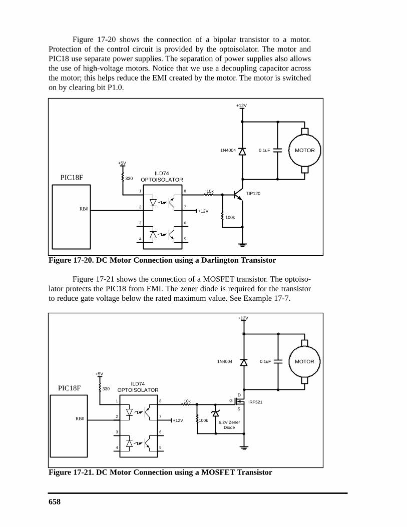
Figure 17-20 shows the connection of a bipolar transistor to a motor.Protection of the control circuit is provided by the optoisolator. The motor andPIC18 use separate power supplies. The separation of power supplies also allowsthe use of high-voltage motors. Notice that we use a decoupling capacitor acrossthe motor; this helps reduce the EMI created by the motor. The motor is switchedon by clearing bit P1.0.
Figure 17-21 shows the connection of a MOSFET transistor. The optoiso-lator protects the PIC18 from EMI. The zener diode is required for the transistorto reduce gate voltage below the rated maximum value. See Example 17-7.
658
1
2
3
4
8
7
6
5
ILD74OPTOISOLATOR
10k TIP120
1N4004 MOTOR
+12V
0.1uF
330
+5V
+12V
8051
P1.0100k
Figure 17-20. DC Motor Connection using a Darlington Transistor
1
2
3
4
8
7
6
5
ILD74OPTOISOLATOR
10k
6.2V Zener Diode
IRF521
1N4004 MOTOR
+12V
0.1uF
GD
S
330
+5V
+12V
8051
P1.0 100k
Figure 17-21. DC Motor Connection using a MOSFET Transistor
PIC18F
PIC18F
RB0
RB0

CHAPTER 17: MOTOR CONTROL: RELAY, PWM, DC, AND STEPPER MOTORS 659
Refer to the figure in this example. Write a program to monitor the status of the switchand perform the following:
(a) If PORTD.7 = 1, the DC motor moves with 25% duty cycle pulse.(b) If PORTD.7 = 0, the DC motor moves with 50% duty cycle pulse.
Solution:
BCF TRISB,RB0 ;PORTB.0 as outputBSF TRISD,RD7 ;PORTD.7 as inputBCF PORTB,RB0 ;turn off motor
CHKBTFSS PORTD,RD7BRA PWM_50BSF PORTB,RB0 ;high portion of pulseCALL DELAYBCF PORTB,RB0 ;low portion of pulseCALL DELAYCALL DELAYCALL DELAYBRA CHK
PWM_50BSF PORTB,RB0 ;high portion of pulseCALL DELAYCALL DELAYBCF PORTB,RB0 ;low portion of pulseCALL DELAYCALL DELAYBRA CHK
Example 17-7
1
2
3
4
8
7
6
5
ILD74OPTOISOLATOR
10k TIP120
1N4004 MOTOR
+12V
0.1uF
330
+5V
+12V
8051
P1.0100k
4.7k
+5V
P2.7
PIC18FRB0
RD7

DC motor control and PWM using CExamples 17-8 through 17-10 show the PIC18 C version of the earlier pro-
grams controlling the DC motor.
660
Refer to Figure 17-18 for connection of the motor. A switch is connected to pin RD7.Write a C program to monitor the status of SW and perform the following:
(a) If SW = 0, the DC motor moves clockwise.(b) If SW = 1, the DC motor moves counterclockwise.
Solution:
#include <p18f458.h>
#define SW PORTDbits.RD7#define ENABLE PORTBbits.RB0#define MTR_1 PORTBbits.RB1#define MTR_2 PORTBbits.RB2
void main(){TRISD=0x80; //make RD7 input pinTRISB=0x0; //make PORTB outputSW = 1;ENABLE = 0;MTR_1 = 0;MTR_2 = 0;
while(1){
ENABLE = 1;if(SW == 1)
{MTR_1 = 1;MTR_2 = 0;
}else
{MTR_1 = 0;MTR_2 = 1;
}}
}
Example 17-8
CHAPTER 17: MOTOR CONTROL: RELAY, PWM, DC, AND STEPPER MOTORS 661
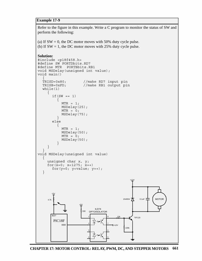
Refer to the figure in this example. Write a C program to monitor the status of SW andperform the following:
(a) If SW = 0, the DC motor moves with 50% duty cycle pulse.(b) If SW = 1, the DC motor moves with 25% duty cycle pulse.
Solution:#include <p18f458.h>#define SW PORTDbits.RD7#define MTR PORTBbits.RB1void MSDelay(unsigned int value);void main()
{TRISD=0x80; //make RD7 input pinTRISB=0xFD; //make RB1 output pinwhile(1)
{if(SW == 1)
{MTR = 1;MSDelay(25);MTR = 0;MSDelay(75);
}else
{MTR = 1;MSDelay(50);MTR = 0;MSDelay(50);
}}
}void MSDelay(unsigned int value)
{unsigned char x, y;for(x=0; x<1275; x++)
for(y=0; y<value; y++);}
Example 17-9
1
2
3
4
8
7
6
5
ILD74OPTOISOLATOR
10k TIP120
1N4004 MOTOR
+12V
0.1uF
330
+5V
+12V
8051
P1.0100k
4.7k
+5V
P2.7
PIC18FRB0
RD7

Review Questions1. True or false. The permanent magnet field DC motor has only two leads for +
and – voltages.2. True or false. Just like a stepper motor, one can control the exact angle of a DC
motor’s move.3. Why do we put a driver between the microcontroller and the DC motor?4. How do we change a DC motor’s rotation direction?5. What is stall in a DC motor?6. True or false. PWM allows the control of a DC motor with the same phase, but
different amplitude pulses.7. The RPM rating given for the DC motor is for __________ (no-load, loaded).
662
Refer to Figure 17-20 for connection to the motor. Two switches are connected to pinsRD0 and RD1. Write a C program to monitor the status of both switches and performthe following:SW2 (RD1) SW1 (RD0)
0 0 DC motor moves slowly (25% duty cycle).0 1 DC motor moves moderately (50% duty cycle).1 0 DC motor moves fast (75% duty cycle).1 1 DC motor moves very fast (100% duty cycle).
Solution:
#include <p18f458.h>#define MTR PORTBbits.RB1void MSDelay(unsigned int value);
void main(){unsigned int duty;TRISB = 0xFD;TRISD = 0xFF;while(1)
{duty = PORTD&0x03;duty++;duty *= 25;MTR = 1;MSDelay(duty);MTR = 0;MSDelay(100-duty);
}}
Example 17-10

SECTION 17.4: PWM MOTOR CONTROL WITH CCP
We examined the CCP (Compare Capture Pulse-Width-Modulation) part ofthe PIC452/458 in Chapter 15. One of the features of the CCP is the pulse widthmodulation (PWM) as we saw in Section 15.4 of Chapter 15. In this section weuse the PWM feature of the CCP to control DC motors. Review the programmingof the PWM in Section 15.4 before embarking on this section.
DC motor control with CCPRecall from Section 15.4 that the PWM part of the CCP is programmed by
using the PR2 and Timer2 registers. Program 17-2 is the rewrite of Example 17-7using the PWM feature of the CCP1. Notice that Program 17-2 is the modified ver-sion of Program 15-5 in Chapter 15. Program 17-2C is the C version of Program17-2. In Program 17-2 (and 17-2C), an input switch is being monitored. If theswitch is low, the PIC18 creates a 50% duty cycle PWM using the CCP1 module.If the switch is high, a 25% duty cycle PWM is created. Recall from Chapter 15that we must use PR2 and Timer2 registers for creating PWM pulses.
;Program 17-2BCF TRISC,CCP1 ;make PWM output pinBSF TRISD,RD7 ;make RD7 input pinMOVLW 0x3C ;PWM MODE, 11 for DC1B1:B0MOVWF CCP1CONMOVLW D'100' ;set period to 100 * Fosc/4MOVWF PR2MOVLW 0x01 ;Timer2, 4 prescale, no postscalerMOVWF T2CON
AGAIN BTFSS PORTD,RD7 ;Is the switch high?BRA T2DUTY ;no, then 50% MOVLW D'25' ;25% duty cycleBRA LOAD
T2DUTY MOVLW D'50' ;50% duty cycle
CHAPTER 17: MOTOR CONTROL: RELAY, PWM, DC, AND STEPPER MOTORS 663
1
2
3
4
8
7
6
5
ILD74OPTOISOLATOR
10k TIP120
1N4004 MOTOR
+12V
0.1uF
330
+5V
+12V
8051
P1.0100k
4.7k
+5V
P2.7
Figure 17-22: DC Motor Control Using CCP1 Pin
PIC18FRC2
RD7

664
BRA LOADLOAD MOVWF CCPR1L ;load duty cycle
CLRF TMR2 ;clear Timer2BSF T2CON,TMR2ON ;turn on Timer2BCF PIR1,TMR2IF ;clear Timer2 flag
OVER BTFSS PIR1,TMR2IF ;wait for end of periodBRA OVERGOTO AGAIN ;continue
The following is the C version of the above program.
//Program 17-2C#include <p18f458.h>void main()
{TRISC = 0xFB; //make CCP1 output pinTRISD = 0x80; //make RD7 input pinCCP1CON = 0x3C; //PWM MODE, 11 for DC1B1:B0PR2=100; //set period to 100 * 16/FoscT2CON=0x01; //4 prescaler, no postscalerwhile(1)
{if(PORTDbits.RD7==1)
CCPR1L = 25; //25% duty cycleelse
CCPR1L = 50; //50% duty cycleTMR2=0x0; //clear Timer2PIR1bits.TMR2IF=0; //clear Timer2 flagT2CONbits.TMR2ON=1; //start Timer2while(PIR1bits.TMR2IF==0);//wait for end of period}
}
Review Questions1. True or false. For standard CCP1, we use the RC2 pin for PWM.2. True or false. For standard CCP1, the CCP1 pin must be configured as output.3. In standard CCP1, we use ___________________ to set the period for PWM.4. In standard CCP1, we use _________________ to set the duty cycle for PWM.5. True or false. In standard CCP1, we must use Timer1 for PWM.

665
SECTION 17.5: DC MOTOR CONTROL WITH ECCP
The PIC18F452/458 (or 4520/4580) comes with one standard CCP and oneenhanced CCP (ECCP). Indeed, in recent years the CCP module has been de-emphasized while the ECCP is becoming more prominent in the PIC18 family.The reason is that ECCP allows the implementation of the H-Bridge for bidirec-tional control of the DC motor in addition to the capture/compare mode present inthe standard CCP. In this section, we use the ECCP feature of the PIC18 to controlthe DC motor. Before embarking on this section, the basic concept of ECCP pro-gramming in Chapter 15 needs to be reviewed.
Bidirectional DC motor control with ECCPECCP allows the implementation of the H-Bridge for bidirectional move-
ment of the DC motor because it uses 4 pins instead of a single pin as is used instandard CCP. As we saw in Section 17.3 of this chapter, the bidirectional DCmovement needs some kind of H-Bridge circuitry. The ECCP module of the PIC18implements the entire H-Bridge circuitry internally. It uses RD7–RD4(PORTD.7–PORTD.4) for this purpose as shown in Figures 17-23 through 17-26.
CHAPTER 17: MOTOR CONTROL: RELAY, PWM, DC, AND STEPPER MOTORS
5RA3/AN3/VREF+
6RA4/T0CKI
RA5/AN4/SS/LVDIN 7
RE0/AN5/RD 8
36
35
34
33
RB3/CANRX
RB2/CANTX/INT2
RB1/INT1
RB0/INT0
9RE1/AN6/WR/C1OUT
10RE2/AN7/CS/C2OUT
VDD 11
VSS 12
32
31
30
29
VDD
VSS
RD7/PSP7/P1D
RD6/PSP6/P1C13OSC1/CLKI
14OSC2/CLK0/RA6
RC0/T1OSO/T1CKI 15
RC1/T1OSI 16
28
27
26
25
RD5/PSP5/P1B
RD4/PSP4/ECCP/P1A
RC7/RX/DT
RC6/TX/CK
17RC2/CCP1
18RC3/SCK/SCL
RD0/PSP0/C1IN+ 19
RD1/PSP1/C1IN- 20
24
23
22
21
RC5/SDO
RC4/SDI/SDA
RD3/PSP3/C2IN-
RD2/PSP2/C2IN+
1MCLR/VPP
2RA0/AN0/CVREF
RA1/AN1 3
RA2/AN2/VREF- 4
40
39
38
37
RB7/PGD
RB6/PGC
RB5/PGM
RB4
PIC18F458
Figure 17-23. ECCP Pins for PWM in PIC18F458/4580 (452/4520)

666
VCC
PIC18F
PLA(RD4)
PLB(RD5)
PLC(RD6)
PLD(RD7)
DCMOTOR
OUTPUT ‘0’
OUTPUT ‘0’
OUTPUT ‘1’
VCC
PIC18F
PLA(RD4)
PLB(RD5)
PLC(RD6)
PLD(RD7)
DCMOTOR
OUTPUT ‘1’
OUTPUT ‘0’
OUTPUT ‘0’
Figure 17-24. Forward Current Flow Using ECCP (from Microchip)
Figure 17-25. Reverse Current Flow Using ECCP (from Microchip)

CHAPTER 17: MOTOR CONTROL: RELAY, PWM, DC, AND STEPPER MOTORS 667
EPWM1M1:EPWM1M0 PWM output pin configuration. It allows the use of a singlepin for the capture/compare mode, or four pins for the PWM. In compare/capture mode, only pin P1A (RD4) is used. In that case, there is no selec-tion for these two bits. In the PWM mode the options for these two bits are as follows:
00 P1A is used as a modulated output. P1B, P1C, and P1D are used as I/O. 01 Full-Bridge output forward. P1D modulated, P1A active. P1B and P1C inactive.
10 Half-Bridge output. P1A and P1D modulated with deadband control, P1C and P1D used as I/O.
11 Full-Bridge output reverse. P1B modulated, P1C active. P1A and P1D inactive.
EDC1B10:EDC1B1 PWM Duty Cycle least-significant bits. Used in PWM only. The least-significant bits (Bit 1 and Bit 0) of the 10-bit duty cycle register are used in PWM. The ECCPR1L register is used as Bit 2 to Bit 9 of the 10-bit duty cycle register.
ECCP1M3–ECC1M0 ECCP1 Mode Select 0 0 0 0 ECCP1 is off0 0 0 1 Reserved
. 0 0 1 0 Compare Mode. Toggle ECCP1 output pin on match. (ECCP1IF bit is set.)
0 0 1 1 Reserved
0 1 0 0 Capture mode, every falling edge0 1 0 1 Capture mode, every rising edge0 1 1 0 Capture mode, every 4th rising edge0 1 1 1 Capture mode, every 16th rising edge
1 0 0 0 Compare mode. Initialize ECCP1 pin low; on compare match, force CCP1 pin HIGH. (ECCP1IF is set.)
1 0 0 1 Compare mode. Initialize CCP1 pin HIGH; on compare match, force CCP1 pin LOW. (ECCP1IF is set.)
1 0 1 0 Compare mode. Generate software interrupt on compare match. (ECCP1IF bit is set, ECCP1 pin is unaffected.)
1 0 1 1 Compare mode. Trigger special event. (ECCP1IF bit is set, and Timer1 or Timer3 is reset to zero.)
1 1 0 0 PWM Mode; P1A, P1C active-HIGH; P1B and P1D active-HIGH1 1 0 1 PWM Mode; P1A, P1C active-HIGH; P1B and P1D active-LOW1 1 1 0 PWM Mode; P1A, P1C active-LOW; P1B and P1D active-HIGH 1 1 1 1 PWM Mode; P1A, P1C active-LOW; P1B and P1D active-LOW
Figure 17-26. ECCP1 Control Register. (This register selects one of the operationmodes of Capture, Compare, or PWM of EECP1)
EPWM1M1 EPWM1M0 EDC1B1 EDC1B0
ECCP1M3 ECCP1M2 ECCP1M1 ECCP1M0D7
D0
668
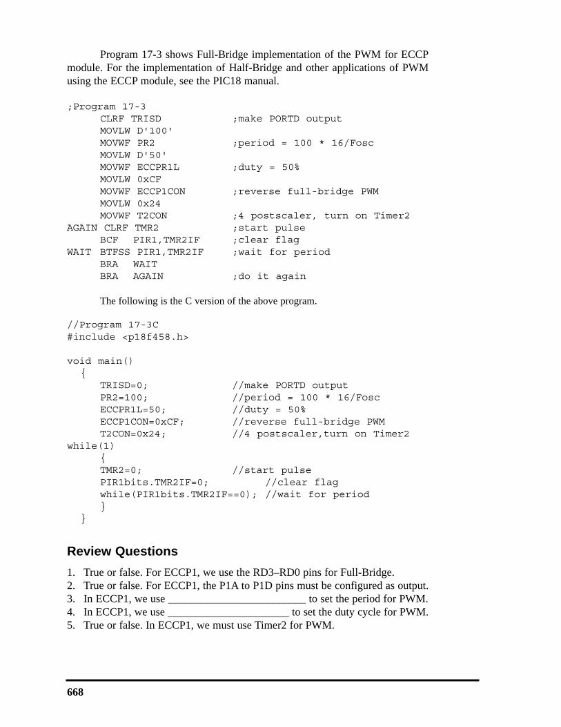
Program 17-3 shows Full-Bridge implementation of the PWM for ECCPmodule. For the implementation of Half-Bridge and other applications of PWMusing the ECCP module, see the PIC18 manual.
;Program 17-3CLRF TRISD ;make PORTD outputMOVLW D'100'MOVWF PR2 ;period = 100 * 16/FoscMOVLW D'50'MOVWF ECCPR1L ;duty = 50%MOVLW 0xCFMOVWF ECCP1CON ;reverse full-bridge PWM MOVLW 0x24MOVWF T2CON ;4 postscaler, turn on Timer2
AGAIN CLRF TMR2 ;start pulseBCF PIR1,TMR2IF ;clear flag
WAIT BTFSS PIR1,TMR2IF ;wait for periodBRA WAITBRA AGAIN ;do it again
The following is the C version of the above program.
//Program 17-3C#include <p18f458.h>
void main(){
TRISD=0; //make PORTD outputPR2=100; //period = 100 * 16/FoscECCPR1L=50; //duty = 50%ECCP1CON=0xCF; //reverse full-bridge PWM T2CON=0x24; //4 postscaler,turn on Timer2
while(1){TMR2=0; //start pulsePIR1bits.TMR2IF=0; //clear flagwhile(PIR1bits.TMR2IF==0); //wait for period}
}
Review Questions1. True or false. For ECCP1, we use the RD3–RD0 pins for Full-Bridge.2. True or false. For ECCP1, the P1A to P1D pins must be configured as output.3. In ECCP1, we use _________________________ to set the period for PWM.4. In ECCP1, we use ______________________ to set the duty cycle for PWM.5. True or false. In ECCP1, we must use Timer2 for PWM.

CHAPTER 17: MOTOR CONTROL: RELAY, PWM, DC, AND STEPPER MOTORS 669
SUMMARY
This chapter continued showing how to interface the PIC18 with real-world devices. Devices covered in this chapter were the relay, optoisolator, step-per motor, and DC motor.
First, the basic operation of relays and optoisolators was defined, alongwith key terms used in describing and controlling their operations. Then the PIC18was interfaced with a stepper motor. The stepper motor was then controlled via anoptoisolator using PIC18 Assembly and C programming languages.
The PIC18 was interfaced with DC motors. A typical DC motor will takeelectronic pulses and convert them to mechanical motion. This chapter showedhow to interface the PIC18 with a DC motor. Then, simple Assembly and C pro-grams were written to show the concept of PWM.
Control systems that require motors must be evaluated for the type ofmotor needed. For example, you would not want to use a stepper in a high-veloc-ity application or a DC motor for a low-speed, high-torque situation. The steppermotor is ideal in an open-loop positional system and a DC motor is better for ahigh-speed conveyer belt application. DC motors can be modified to operate in aclosed-loop system by adding a shaft encoder, then using a microcontroller tomonitor the exact position and velocity of the motor. In the last two sections, weshowed how to use CCP and ECCP features of PIC18 to control DC motors.
PROBLEMS
SECTION 17.1: RELAYS AND OPTOISOLATORS
1. True or false. The minimum voltage needed to energize a relay is the same forall relays.
2. True or false. The minimum current needed to energize a relay depends on thecoil resistance.
3 Give the advantages of a solid-state relay over an EM relay.4. True or false. In relays, the energizing voltage is the same as the contact
voltage.5. Find the current needed to energize a relay if the coil resistance is 1,200 ohms
and the coil voltage is 5 V.6. Give two applications for an optoisolator.7 Give the advantages of an optoisolator over an EM relay.8. Of the EM relay and solid-state relay, which has the problem of back EMF?9. True or false. The greater the coil resistance, the worse the back EMF voltage.10. True or false. We should use the same voltage sources for both the coil voltage
and contact voltage.
SECTION 17.2: STEPPER MOTOR INTERFACING
11. If a motor takes 90 steps to make one complete revolution, what is the stepangle for this motor?
12. Calculate the number of steps per revolution for a step angle of 7.5 degrees.

13. Finish the normal four-step sequence clockwise if the first step is 0011 (binary).
14. Finish the normal four-step sequence clockwise if the first step is 1100 (binary).
15. Finish the normal four-step sequence counterclockwise if the first step is 1001(binary).
16. Finish the normal four-step sequence counterclockwise if the first step is 0110(binary).
17. What is the purpose of the ULN2003 placed between the PIC18 and the step-per motor? Can we use that for 3A motors?
18. Which of the following cannot be a sequence in the normal four-step sequencefor a stepper motor? (a) CCH (b) DDH (c) 99H (d) 33H
19. What is the effect of a time delay between issuing each step?20. In Question 19, how can we make a stepper motor go faster?
SECTION 17.3: DC MOTOR INTERFACING AND PWM
21. Which motor is best for moving a wheel exactly 90 degrees?22. True or false. Current dissipation of a DC motor is proportional to the load.23. True or false. The rpm of a DC motor is the same for no-load and loaded.24. The rpm given in data sheets is for ___________ (no-load, loaded).25. What is the advantage of DC motors over AC motors?26. What is the advantage of stepper motors over DC motors?27. True or false. Higher load on a DC motor slows it down if the current and volt-
age supplied to the motor are fixed.28. What is PWM, and how is it used in DC motor control?29. A DC motor is moving a load. How do we keep the rpm constant?30. What is the advantage of placing an optoisolator between the motor and the
microcontroller?
ANSWERS TO REVIEW QUESTIONS
SECTION 17.1: RELAYS AND OPTOISOLATORS
1. With a relay we can use a 5 V digital system to control 12 V–120 V devices such as horns andappliances.
2. Because microcontroller/digital outputs lack sufficient current to energize the relay, we need adriver.
3. When the coil is not energized, the contact is closed.4. When current flows through the coil, a magnetic field is created around the coil, which caus-
es the armature to be attracted to the coil.5. It is faster and needs less current to get energized.6. It is smaller and can be connected to the microcontroller directly without a driver.
SECTION 17.2: STEPPER MOTOR INTERFACING
1. 0110, 0011, 1001, 1100 for clockwise; and 0110, 1100, 1001, 0011 for counterclockwise2. 723. Because the microcontroller pins do not provide sufficient current to drive the stepper motor
670

SECTION 17.3: DC MOTOR INTERFACING AND PWM
1. True2. False3. Because microcontroller/digital outputs lack sufficient current to drive the DC motor, we need
a driver.4. By reversing the polarity of voltages connected to the leads5. The DC motor is stalled if the load is beyond what it can handle.6. False7. No-load
SECTION 17.4: PWM MOTOR CONTROL WITH CCP
1. True2. True3. PR24. CCPR1L5. False
SECTION 17.5: DC MOTOR CONTROL WITH ECCP
1. False2. True3. PR24. CCPR1L5. True
CHAPTER 17: MOTOR CONTROL: RELAY, PWM, DC, AND STEPPER MOTORS 671

672