Embed Size (px)
Citation preview

24 October 2013 Motion Imagery Standard Board 1
1 Scope
Motion imagery data is generated by many different sensors, distributed across many different
networks and received by many different users and systems. To coordinate analysis, manage and
generally prevent confusion with such a large number of motion imagery sources, it is important
to define a consistent name or identity for each source.
This Standard (ST) defines (a) the required identification elements that shall be inserted into
motion imagery streams or files, (b) where in the motion imagery data flow (i.e. from source to
user) the insertions shall happen and (c) the insertion techniques, formats and locations within
streams and files. This Standard also provides guidance in extracting Universal Unique
Identifiers (UUID) for use as enterprise identifiers of Motion Imagery Systems.
In addition to the required identifiers there are many supplemental identifiers which can be
included in the metadata for varying purposes. This Standard provides an overview of the
supplemental identifiers but does not require or define them; however, these additional
identifiers are documented in RP 1301.1.
The Motion Imagery Identification System (MIIS) provides solutions to four problems:
(1) Determining whether two (or more) streams, or motion imagery files, are from the same
source (sensor/platform).
(2) Determining whether two (or more) streams, or motion imagery files, are from two
different sources.
(3) Basis for pedigree information about the video (i.e. keep track of all motion imagery
manipulations that have occurred).
(4) Linking useful identifying information about the stream or motion imagery file to the
motion imagery.
When fully implemented, the MIIS fulfills the need to provide a consistent and unique identifier
for all sensors and platforms.
2 References
2.1 Normative References
[1] ISO/IEC 8825-1:2008, Information technology – ASN.1 encoding rules: Specification of
Basic Encoding Rules (BER), Canonical Encoding Rules (CER) and Distinguished
Encoding Rules (DER)
STANDARD Motion Imagery Identification System (MIIS)
Core Identifier
MISB ST 1204.1
24 October 2013

ST 1204.1.1 - Motion Imagery Identification System - Core Identifier
24 October 2013 Motion Imagery Standard Board 2
[2] ITU-T X.667 – Procedures for the operation of Object Identifier Registration Authorities:
Generation of Universally Unique Identifiers and their use in object identifiers, Oct 2012
[3] IETF RFC 4122 - A Universally Unique IDentifier (UUID) URN Namespace, Jul 2005
[4] ISO/IEC 14977:1996, Information Technology -- Syntactic meta-language – Extended
BNF
[5] NGA.RP.0001_1.0.0 - NGA Recommended Practice for Universally Unique Identifiers
Version 1.0.0, Jan 2013
[6] MISB ST 0605.3 Inserting Time Stamps and Metadata in High Definition Uncompressed
Video, Jun 2011
2.2 Informative References
[7] NIST 800-90A - Recommendation for Random Number Generation Using Deterministic
Random Bit Generators, Jan 2012
[8] MISB ST 0604.2 Time stamping and Transport of Compressed Motion Imagery and
Metadata , Jun 2011
[9] NSG Metadata Foundation (NMF) Part 1 Version 2.1, Mar 2012
[10] SMPTE ST 336:2007 Data Encoding Protocol Using Key-Length-Value
[11] XML Schema - http://www.w3.org/XML/Schema
[12] MISB RP 1301.1 Motion Imagery Identification System - MIIS - Augmentation Data, Oct
2013
[13] A check digit system for hexadecimal numbers by Dr. Markku Niemenmaa, Department of
Mathematical Sciences, University of Oulu, 90014 Oulu, Finland
[14] On some properties of a check digit system by Dr. Markku Niemenmaa and others, 2012
IEEE International Symposium on Information Theory Proceedings
[15] SMPTE ST 292-1:2012 1.5 Gb/s Signal/Data Serial Interface
[16] SMPTE ST 424:2012 3 Gb/s Signal/Data Serial Interface
[17] MIL-STD-1472G - Human Engineering - 11 Jan 2012 (Section 5.2.2.4.2)
3 Terms and Definitions
FMV Full Motion Video
WAMI Wide Area Motion Imagery

ST 1204.1.1 - Motion Imagery Identification System - Core Identifier
24 October 2013 Motion Imagery Standard Board 3
4 Revision History
Revision Date Summary of Change
RP 1204 6/4/2012 Initial Revision
ST 1204.1 10/24/2013
Updated to Standard
Absolute Identifier (AID) was modified and renamed to
Functional Core Identifier
Relative Identifier (AID) was modified and renamed to Minor
Core Identifier
Changed Device ID
o Based on UUID
o Contexts to enable different levels of compliance
(physical versus virtual versus managed)
Changed Text Format to support UUIDs and added better
check byte method
Moved Augmentation Identifier’s to RP 1301.1
o Changed KLV from a Local Data Set to a Single KLV
data item.
Document structure and editorial changes
Removed SEI Messages
5 Overview
Motion Imagery data, which includes uncompressed Video, FMV and WAMI, is generated by
many platforms and disseminated to many systems as illustrated in Figure 1 below.
Figure 1: Conceptual Data Flow
Figure 1 shows the typical data flow which is composed of three components, the data sources
(e.g. UAV), the dissemination (e.g. DISA) and the data receivers or users (e.g. NGA). There are
many different types of users that can use the Motion Imagery data including: Sensor drivers,
Motion Imagery
SourcesMotion Imagery
Dissemination
Motion Imagery
Users
Which is which?
Is this different
than…?
Is this the same
as…?

ST 1204.1.1 - Motion Imagery Identification System - Core Identifier
24 October 2013 Motion Imagery Standard Board 4
Soldiers, Mission Coordinators, Exploiters, Production personnel, Photogrammetrists,
Historians, Archivists, Security and Lawyers. Users need to be able to ID their Motion Imagery
plus coordinate activities across the whole (world-wide) user base. To achieve this, users need to
know the identity of their data source plus any supporting contextual information. To provide
this information two classes of identifiers are needed: Core Identifiers and Augmentation
Identifiers. The purpose of a Core Identifier is to provide a unique “name” for a motion
imagery source; therefore, they are required in every motion imagery dataset (stream or file).
Motion Imagery data is communicated in two formats, analog and digital. Analog Motion
Imagery does not provide sufficient metadata support for this Standard, and therefore is not
discussed. Digital Motion Imagery does provide support for identifiers to be added directly to the
imagery frames and accompanying metadata. The purpose of Augmentation Identifiers is to
provide the contextual information which is information about the data source and its usage (e.g.
Mission IDs, ATO’s, feed color). The Motion Imagery Identification System (MIIS) is a
combination of both a Core Identifier and a list of Augmentation Identifiers as shown in Figure
2.
Figure 2: MIIS Identifier
Augmentation identifiers conform to specific situations and applications so there is not a
required list of items to use in all motion imagery streams. Since Augmentation Identifiers are
not required they are not included in this Standard. Augmentation Identifiers are however
recommended, and they are documented in RP 1301.1. ST 1204.1 discusses only the Core
Identifier from this point forward.
Requirement
ST 1204.1-01 All MIIS Compliant Digital Motion Imagery data shall contain a Core identifier in either the imagery frames or metadata or both.
5.1 Core Identifier
Core Identifiers are a collection of up to three Identifier Components that are combined to form
a unique name for the Motion Imagery data. The Identifier Components are UUIDs and can be
generated and inserted at different points during the creation and/or dissemination of the Motion
Imagery.
Identifier Component generation can be performed either during the manufacture of a device or
on an as-needed basis throughout the data flow. The generation means to create a UUID either
from unique device information (serial numbers, model numbers, etc.) or from a random number
Core Identifier
MIIS
Augmentation
List of Information
RP1301

ST 1204.1.1 - Motion Imagery Identification System - Core Identifier
24 October 2013 Motion Imagery Standard Board 5
generator, as described in Appendix A. Identifier Component insertion means to include the
Identifier Component into the motion imagery data consistent with the format of the motion
imagery data (e.g. SMPTE 292, MPEG2 Transport Stream). The Identifier Component is either
added to an existing Core Identifier or a new Core Identifier is created. Ideally, when the
insertion occurs the identifier will be frame accurate which is important for platforms that have
multiple sensors.
There are two types of Core Identifiers, Foundational and Minor. A Foundational Core
Identifier is composed of up to three Identifier Components: a Sensor Device Identifier, a
Platform Device Identifier, and a Window Identifier. Foundational Core Identifiers are
constructed only when the device and/or window identifiers are known, which limits their
insertion either on-board the platform or at a control station (e.g. Ground Control Station for a
UAS system). A Minor Core Identifier is composed of a single Identifier Component that is a
randomly generated UUID. Minor Core Identifiers are only generated and inserted after the
platform; they cannot be used on-board platforms. Figure 3 illustrates the Core Identifier and its
types.
Figure 3: Core Identifier Types
The quality of the Core Identifier is dependent on where in the data flow the Identification
Components are generated and inserted. A high quality Core Identifier means that: it is the same
identifier used by all users of the Motion Imagery (ubiquitous), it is unique across all
sensors/platforms, and the physical data source (i.e. Sensor, Platform and optional Window) can
be determined from the identifier. Alternatively, the lowest quality Core Identifier only provides
the same identifier for a subset of the users, typically at a single site. Normally the earlier the
identifier is inserted into the Motion Imagery data the higher the Identifier quality. For example,
if all of the Identifier Components are generated and inserted into the Motion Imagery on-board
the Sensor/Platform then, the Core Identifier quality will be high because every user will have
the same Identifier. Alternatively, if the Identifier is inserted into the Motion Imagery at a user’s
site (at the user end of the data flow) then the Core Identifier quality will be low because each
end user group would have different Identifiers for the same Motion Imagery.
For users of the identifiers to understand the Core Identifier quality, the Identifier Component
includes information about where it is inserted. There are four basic generation/insertion points:
(1) automatically within the sensor/platform; (2) on-board the platform from a host computer
(e.g. generated by flight computer, inserted by encoder); (3) within a control station; and (4) any
OR
Foundation ID Minor ID
Core Identifier
Device
ID
Sensor
Platform
WindowDevice
IDUUID UUID

ST 1204.1.1 - Motion Imagery Identification System - Core Identifier
24 October 2013 Motion Imagery Standard Board 6
point from the control station to the end user. When an Identifier Component is created one of
these four Identifier quality values is included with the Identifier, so that end users know the
limits of the identifier.
All Core Identifiers should have the following important properties:
1) Unique – no two Core Identifier values are the same amongst any data sources,
2) Compact – the identifiers are repeated in the stream frequently, so they need to be bit
efficient,
3) Anonymous – the source of the Identifier Component is untraceable,
4) Automatic – the Identifier Component is not dependent on human intervention for
generation,
Foundational Core Identifiers should also have the following properties:
5) Persistent – the same Identifier Component is used after a system has been powered off
and on,
6) Consistent - the same Identifier Component is used for a particular device even if it has
been physically separated from one host device and connected to a different host device,
7) Ubiquitous - the Core Identifier is the same for all users to determine similarity or
distinctness,
8) Frame Accurate - the correct Core Identifier is accessible for every frame of the
imagery.
9) Sensor Identification - the Core Identifier can be used to determine which sensor is
being used,
10) Platform Identification - the Core Identifier can be used to determine which platform is
being used.
In order to support all of the types of users, listed in Section 5, all ten of these properties must be
included in the Core Identifier.
5.1.1 Foundational Core Identifier
The purpose of the Foundational Core Identifier is to provide a well-defined, unique and
persistent identifier directly for a Motion Imagery data source. Foundational Core Identifiers are
inserted within the Motion Imagery either on-board the platform, before any storage or
transmission of the Motion Imagery from the platform, or within the control station of the
sensor/platform.
Foundational Core Identifiers are constructed from up to three Identifier Components: Sensor
Identifier, Platform Identifier and Window Identifier. The Sensor and Platform Identifiers are
Device Identifiers that can be generated and inserted at three different insertion points in the data
flow: (1) automatically within the sensor/platform device (Physical Identifier), (2) on-board the
platform from a host computer (e.g. generated by flight computer, inserted by encoder) (Virtual
Identifier), or (3) from a control station (Managed Identifier). Figure 4 illustrates the Device
Identifier and its types.

ST 1204.1.1 - Motion Imagery Identification System - Core Identifier
24 October 2013 Motion Imagery Standard Board 7
Figure 4: Device Identifier
The Window Identifier is a simple UUID identifier that is generated and inserted when a sub-
section of the Motion Imagery frame is extracted from the full frame imagery.
A Physical Identifier is generated or stored within the device itself and never changes over the
lifetime of the device. Should the device be power cycled the exact same identifier is provided
(i.e. persistent). Likewise, if the device is removed from the system and later re-integrated (or
moved to another system) the same identifier is provided for that device (i.e. consistent).
Physical Identifiers are frame accurate, meaning they are included with every frame of the
motion imagery data. For example, a Physical Sensor Identifier is included in the raw imagery
(e.g. VANC) of a sensor’s output. To prevent misidentifying the motion imagery Physical
Identifiers are inserted only by the devices themselves; therefore no devices will generate, store
or use predefined Physical Device Identifiers for other devices.
A Virtual Identifier is generated or stored outside of the physical device by an external host
device (e.g. flight computer), and is managed by the host so that it is persistent; if the device or
host is power cycled the exact same identifier is used (i.e. persistent). When a device is swapped
out or replaced with a new device the host will need to manage the change to the Virtual
Identifier, meaning that the Virtual Identifier will need to be changed. Virtual Identifiers must be
inserted into all copies of the Motion Imagery Data that is sent from, or stored on, the platform -
this maintains the ubiquitous nature of the identifier. Virtual Identifiers do not need to be frame
accurate, but they must be changed within the required time window, as specified by requirement
ST 1204.1-12.
A Managed Identifier is generated or stored on the control station (e.g. Ground Control Station
(GCS)), and is managed by the control station so that it is persistent; if the devices or control
station are power cycled the exact same identifier is used (i.e. persistent). When a device is
swapped out or replaced with a new device the control station will need to change the Managed
Identifier. Managed Identifiers do not need to be frame accurate, but they must be changed
within the required time window, as specified by requirement ST 1204.1-16.
The difference between a Virtual Identifier and Managed Identifier is that the Virtual Identifier
will be ubiquitous while the Managed Identifier will only serve users after the control station i.e.
the Virtual Identifier will be higher Identifier quality than the Managed Identifier.
Device
ID
Physical
ID
Virtual
ID
UUIDUUID
OR
Managed
ID
UUID

ST 1204.1.1 - Motion Imagery Identification System - Core Identifier
24 October 2013 Motion Imagery Standard Board 8
Physical Identifiers are preferred because they are independently inserted into the motion
imagery data and are less prone to error (i.e. they are plug-n-play); however, Physical Identifiers
potentially require an upgrade to the device’s hardware. Virtual and Managed Identifiers can be
implemented with software upgrades; however, systems that use them will have greater data
management overhead and may rely on some human interaction and input, which can be error
prone.
Systems can construct Foundational Core Identifiers using different types of Sensor and Platform
Identifiers. For example, a sensor may generate a Physical Identifier and the platform may
generate a Virtual Identifier.
Since the Sensor device and Platform identifiers can either be Physical, Virtual or Managed then
there are several possible levels of Identifier quality which are listed in Table 1 from highest
quality to lowest quality.
Table 1: Device Identifier Types
Identifier
Quality Level Sensor Platform
1 Physical Physical
2 Physical Virtual
3 Physical Managed
4 Virtual Physical
5 Virtual Virtual
6 Virtual Managed
7 Managed Physical
8 Managed Virtual
9 Managed Managed
A goal of this Standard is for all systems to implement the highest Identifier Quality Level, i.e.
Identifier Quality Level 1, for the Sensor and Platform.
Sensor Identifiers
The definition of “Sensor” varies depending on the context in which it is used. For ST1204 the
definition of a Sensor is the device that is converting some optical (or other) phenomenon into an
electrical signal. For example, the Sensor Identifier is associated to a focal plane array and its
electronics; however, the Sensor Identifier is not the identifier for the gimbal ball or lens system
because a gimbal may have multiple cameras mounted within them, and, the lens system is not
converting optical phenomenon into electrical signals. Identifiers for these other devices, such as
the gimbal ball or lens system, can be added as augmentation identifiers (see RP 1301.1).
As discussed in Section 5.1.1, the Sensor Identifier can either be a Physical, Virtual, or Managed
Device Identifier, which is denoted by the Sensor-ID-Type.
The definition of a Physical Sensor Identifier is an identifier that is automatically generated (i.e.
with no human interaction) and inserted into the Motion Imagery data by the sensor device.
The definition of a Virtual Sensor Identifier is an identifier that is generated or stored on-board
the platform by a host (e.g. flight computer) and inserted into all copies of the Motion Imagery

ST 1204.1.1 - Motion Imagery Identification System - Core Identifier
24 October 2013 Motion Imagery Standard Board 9
data before storage and/or transmission. Virtual Sensor Identifiers do not have to be automatic
and can be manually entered if needed.
The definition of a Managed Sensor Identifier is an identifier that is generated or stored within
the control station of the platform/sensor and inserted into the Motion Imagery data before
exploitation within the control station and/or dissemination from the control station.
A Physical Sensor Identifier provides the highest Identifier quality, followed by a Virtual Sensor
Identifier, and finally the lowest Identifier quality is the Managed Sensor Identifier.
For multi-sensor systems that mosaic multiple motion imagery frames into one large frame (e.g.
WAMI) or fuse multiple sensor images into one image, refer to Section 5.1.1.1.1 for
requirements and guidance on the Multi-Sensor Identifier generation.
One of the goals of this standard is for systems to provide consistent and persistent identifiers as
much as possible. The following requirements promote this goal by ensuring that the identifiers
only change when necessary.
Requirement
ST 1204.1-02 The Sensor Identifier shall identify the physical device that is detecting some optical (or other) phenomenon.
ST 1204.1-03 The Sensor ID shall be a UUID that is generated following the guidelines in Appendix A.
ST 1204.1-04 When MIIS Compliant Sensors that provide a digital output (e.g. SMPTE 292) are used, the output shall include a Sensor Identifier.
ST 1204.1-05 When a Sensor Identifier is a Physical Sensor Identifier (as defined in Section 5.1.1.1), the Sensor-ID-Type shall be “Physical”.
ST 1204.1-06 When a Sensor has a Physical Sensor Identifier, the Sensor shall insert the Physical Device Identifier into every frame of uncompressed motion imagery data.
ST 1204.1-07 When a Sensor has a Physical Sensor Identifier and the Sensor is power cycled, the Sensor shall use the same Physical Sensor Identifier.
ST 1204.1-08 When a Sensor has a Physical Sensor Identifier and the Sensor is disconnected from a system and reattached to the same system or alternate system, the Sensor shall use the same Physical Sensor Identifier.
ST 1204.1-09 When a Sensor Identifier is a Virtual Sensor Identifier (as defined in Section 5.1.1.1), the Sensor-ID-Type shall be “Virtual”.
ST 1204.1-10 When a system uses a Virtual Sensor Identifier and the Sensor or host is power cycled, the system shall use the same Virtual Sensor Identifier.
ST 1204.1-11 When a system uses a Virtual Sensor Identifier and the Sensor is replaced with a new Sensor, the host shall change or generate a new Virtual Sensor Identifier for the new Sensor.

ST 1204.1.1 - Motion Imagery Identification System - Core Identifier
24 October 2013 Motion Imagery Standard Board 10
ST 1204.1-12 If a Virtual Sensor Identifier is being used then the host device shall ensure that the proper Virtual Sensor Identifier is inserted into the motion imagery at the correct time (e.g. when a sensor change occurs) to within a system defined value number or fraction of seconds (nominally ½ second) of the change.
ST 1204.1-13 When a Sensor Identifier is a Managed Sensor Identifier (as defined in Section 5.1.1.1), the Sensor-ID-Type shall be “Managed”.
ST 1204.1-14 When a system uses a Managed Sensor Identifier and the Sensor or Control station is power cycled, the system shall use the same Managed Sensor Identifier.
ST 1204.1-15 When a system uses a Managed Sensor Identifier and the Sensor is replaced with a new Sensor, the control station shall change or generate a new Managed Sensor Identifier for the new Sensor.
ST 1204.1-16 If a Managed Sensor Identifier is being used then the control station shall ensure that the proper Managed Sensor Identifier is inserted into the motion imagery at the correct time (e.g. when a sensor change occurs) to within a system defined value number or fraction of seconds (nominally ½ second) of the change.
ST 1204.1-17 When Motion Imagery data contains a Sensor Identifier no MIIS system shall replace the Sensor Identifier with another Sensor Identifier.
5.1.1.1.1 Multi-Sensor Systems
Some systems generate frames of motion imagery from a collection of sensors, such as, Wide
Area Motion Imagery (WAMI) systems or sensor fusing systems. In order for the resulting
composite motion imagery to have one consistent Sensor Identifier assigned, the Sensor
Identifiers from each Sensor are combined into one Sensor Identifier by using the UUID Hashing
method outline in Appendix A.
If the sensor configuration changes (i.e. a sensor is swapped out) then the resulting Sensor
Identifier hashed value will change as well, indicating to end users or systems that a change was
made which could flag the need for updating image calibration, etc. Figure 5 illustrates an
example of a multiple sensor data flow. The figure shows sensors on the left (blue) with each
sensor having its own Sensor Identifier (IDs 1 through 4). The Sensor Identifiers are combined
using a UUID Hash algorithm to produce Sensor ID-A which is used both in the mosaic frame
data and each individual FMV stream. Each individual FMV stream is extracted (i.e. window)
from the full frame data so each is assigned a Window Identifier.

ST 1204.1.1 - Motion Imagery Identification System - Core Identifier
24 October 2013 Motion Imagery Standard Board 11
Figure 5: Example WAMI Data Flow
When a sensor is replaced, e.g. because of sensor failure, the UUID Hash will produce a different
Sensor ID-A value, indicating that there has been an overall change in the sensing system.
Requirements for Multi-Sensor Identifiers:
Requirement
ST 1204.1-18 When a MIIS compliant multiple sensor system is used to form a single Motion Imagery source, the Sensor Identifier’s UUIDs from each source shall be combined into one UUID using the UUID Hashing technique from Appendix A.
ST 1204.1-19 When multiple sensors are used to form a single Sensor Identifier, the Sensor-ID-Type shall be the lowest Identifier quality Sensor-ID-Type of the group.
Platform Identifiers
Platforms are typically collections of devices that are grouped together around a physical
structure or skeletal-frame. The devices (e.g. flight computers, sensors, robotic arms, etc.) can be
swapped in and out and potentially moved to other platforms. To provide consistency, in this
Standard the Platform is defined as the physical structure or skeletal-frame that the devices are
physically connected to. This definition prevents the Platform Identifier from moving with one of
the devices (i.e. a flight computer moved from one platform to another does not maintain the
same identifier).
As discussed in Section 5.1.1, the Platform Identifier can either be a Physical, Virtual or
Managed Device Identifier, which is denoted by the Platform-ID-Type.
A Physical Platform Identifier is defined as an identifier that is discoverable on-board without
human interaction and inserted into all copies of the Motion Imagery data before storage and/or
transmission. Since the platform structure or skeletal-frame is not an electrical device it will need
some form of physical tagging that can be used to automatically provide or enable the generation
Sensor
1
Sensor
2
Sensor
3
Sensor
4
Sensor
ID1
Sensor
ID2
Sensor
ID3
Sensor
ID4
FMV
Window
Creation
Sensor
ID-A
Platform
ID
Window
ID1
Platform
ID
Sensor
ID-A
Window
ID2
Platform
ID
Sensor
ID-A
Window
ID3
Platform
ID
Sensor
ID-AFrame
Generation
(Mosaic)
Platform
ID
Sensor
ID-A LibFull Size
Frame Storage
FMV Stream 1
FMV Stream 2
FMV Stream 3
UUID Hash

ST 1204.1.1 - Motion Imagery Identification System - Core Identifier
24 October 2013 Motion Imagery Standard Board 12
of the Physical Platform Identifier. For example with an aircraft the identifier could be based on
a serial number of the aircraft frame that is automatically scanned during power-up.
The definition of a Virtual Platform Identifier is an identifier that is generated or stored on-board
the platform by a host (e.g. flight computer) and inserted into all copies of the Motion Imagery
data before storage and/or transmission. Virtual Platform Identifiers do not have to be automatic
and can be manually entered if needed.
The definition of a Managed Platform Identifier is an identifier that is inserted within the control
station of the platform/sensor.
A Physical Platform Identifier provides the highest Identifier quality, followed by a Virtual
Platform Identifier, and finally the lowest Identifier quality is the Managed Platform Identifier.
The Platform ID is not required if a platform is not associated with the sensor. For example, a
handheld camera does not have a platform so a Platform ID is not required. For ground based
static mounted sensors (i.e. sensors mounted on poles, fences or buildings) the Platform ID is
optional but recommended.
One of the goals of this standard is for systems to provide consistent and persistent identifiers as
much as possible. The following requirements promote this goal by ensuring that the identifiers
only change when necessary.
Requirement
ST 1204.1-20 The Platform Identifier shall identify the physical device (or skeletal-frame) that the sensor is physically attached to (i.e. aircraft, UAV, Humvee, etc.)
ST 1204.1-21 The Platform Identifier shall be a UUID that is generated following the guidelines in Appendix A.
ST 1204.1-22 When a Platform Identifier is a Physical Platform Identifier (as defined in Section 5.1.1.2), the Platform-ID-Type shall be “Physical”.
ST 1204.1-23 When a Platform Identifier is a Virtual Platform Identifier (as defined in Section 5.1.1.2), the Platform-ID-Type shall be “Virtual”.
ST 1204.1-24 When a Platform Identifier is a Managed Platform Identifier (as defined in Section 5.1.1.2), the Platform-ID-Type shall be “Managed”.
ST 1204.1-25 Platform Devices shall be generate and insert Platform Device Identifiers into Motion Imagery data.
Window Identifier
The Window Identifier identifies an area of interest that may be extracted from a motion
imagery source. This Identifier is needed only when sub-images of a motion imagery data set are
created and/or transmitted. For example a WAMI data source may have multiple users extracting
windows from the full frame data and forming FMV streams. Each stream would have identical
Sensor Identifier and Platform Identifier, so a Window Identifier is required to enforce the
uniqueness requirement. The Window Identifier is a UUID that is generated following the
guidelines in Appendix A.

ST 1204.1.1 - Motion Imagery Identification System - Core Identifier
24 October 2013 Motion Imagery Standard Board 13
Requirement
ST 1204.1-26 When a window of Motion Imagery data is being extracted from an existing Motion Imagery data set, the resulting motion imagery data shall contain a copy of the original Foundational Identifier, if one exists, with a Window Identifier included.
5.1.2 Minor Core Identifiers
The purpose of the Minor Core Identifier is to support a low level of identification when a
Foundational Core Identifiers are not used. Minor Core Identifiers can be generated and inserted
into motion imagery streams or files at any time after the collection process but only if a
Foundational Core Identifier is not already present. The Minor Core Identifier is a UUID and
they are primarily for legacy systems and devices, where a legacy device or system is defined as
one that does not support Foundational Core Identifiers.
There are no requirements for when Minor Core Identifiers change so it is left up to the system
implementation to determine when to switch to a new Minor Core Identifier. For example, if a
distribution system is able to detect that a mission has been completed or a new mission started, a
new Minor Core Identifier could be generated and inserted for that mission. Alternatively, a new
Minor Core Identifier could be generated for a specific time interval (i.e. every twelve hours).
There is no guarantee that Minor Core Identifiers will change to match missions or source
changes and, since they are inserted downstream from some users of the motion imagery, they
are considered inadequate to satisfy the four problems listed in Section 1 (for all users).
Requirement
ST 1204.1-27 When Motion Imagery data does not contain a Foundational Core Identifier and the Motion Imagery data has been transmitted from the platform then a MIIS Compliant system shall create a Minor Core Identifier and insert it into the Motion Imagery Data.
ST 1204.1-28 When Motion Imagery data includes a Foundational Core Identifier then a Minor Core Identifier shall NOT be used, generated or inserted into the Motion Imagery data.
ST 1204.1-29 Sensors and/or Platforms shall generate only Foundational Core Identifiers.
ST 1204.1-30 The Minor Core Identifier shall be a UUID that is generated following the guidelines in Appendix A.
5.1.3 Core Identifier Configuration Data
In addition to the raw Identifier Components UUID values, information about the version of the
Core Identifier and the Identifier Quality of each Identifier Components is needed.

ST 1204.1.1 - Motion Imagery Identification System - Core Identifier
24 October 2013 Motion Imagery Standard Board 14
Version
The Version number of the Core Identifier is used to support future changes of this Standard.
The Core Identifier always contains the version number as the first value so that parsers can read
this value and determine how to interpret the rest of the Core Identifier values. The Version is a
number that matches the version of this Standard (E.g. Standard 1204.1 would use a version
value of “1”, Standard 1204.2 would use a version value of “2”, etc.).
Identifier Quality Data and Usage Value
In order to properly interpret the meaning of the Core Identifier some additional Identifier
Quality data is included for each Identifier Component (i.e. Sensor, Platform, Window
Identifiers, and Minor Identifier). The combination of Identifier Quality data for the Sensor,
Platform, Window and Minor Identifiers (in that order) is called the Usage Value. For the Sensor
and Platform Device Identifiers there are four possible Identifier Quality values to assign:
Physical, Virtual, Managed or None. For the Window and Minor Identifiers there are only two
possible values, Included or None. Table 2 lists the possible Identifier Quality values for each
Identifier Component that can be used.
Table 2: Identifier Component Quality Values
Sensor Identifier
Quality
Platform Identifier
Quality
Window Identifier
Quality
Minor Identifier
Quality
Physical Physical Included Included
Virtual Virtual None None
Managed Managed
None None
5.1.4 Foundational Core Identifier Implementation
There are two special cases that can be used to reduce the processing during identification
insertion: Pass back and Pre-fill.
Pass back refers to a situation where the Platform Identifier (Physical or Virtual) is passed
“backwards” to the sensor in real time, so that the sensor can use it to construct a complete
Foundational Core Identifier. This can eliminate the need for processing within the platform,
since the Platform Identifier insertion is being performed within the sensor. For example, if the
sensor produces compressed motion imagery then, by using pass back, the platform does not
need to update the Foundational Core Identifier; the Platform Identifier information is inserted
into the motion imagery during the compression process within the Sensor.
Pre-fill refers to a situation where a sensor produces a Foundational Core Identifier with a
temporary ID for the Platform ID. The temporary ID can then be replaced by the platform
without affecting the bandwidth of the motion imagery (i.e. this prevents the need for de-
multiplexing and then re-multiplexing the MPEG2 Transport Stream). The value for the
temporary ID is the nil UUID [3], which is 16 bytes of the hex value “0x00” or
“0x00000000000000000000000000000000”.

ST 1204.1.1 - Motion Imagery Identification System - Core Identifier
24 October 2013 Motion Imagery Standard Board 15
Requirement
ST 1204.1-31 When MIIS Compliant Sensor pre-fills (see Section 5.1.4) the Foundational Core Identifier with a temporary value for the Platform Identifier, the only value that shall be used for the temporary value is 0x00000000000000000000000000000000.
ST 1204.1-32 When the MIIS Compliant Sensor motion imagery data, which contains a Foundational Core Identifier, leaves the platform or is stored on the platform, the Foundational Core Identifier shall be fully formed with no temporary Identifiers.
5.2 MIIS Core Identifier Summary
Figure 6 illustrates the complete structure of the MIIS Core Identifier, which includes Version
and Usage Values (“Vers+Usage”) for the Core Identifier.
Figure 6: Complete MIIS Identifier
Although Figure 6 shows the full hierarchy of Core Identifier structure, the only data that is
potentially transmitted are the values in green.
A Physical based Foundational Core Identifier is defined as a Foundational Core Identifier with
both a Physical Sensor Identifier and Physical Platform Identifier. A Physical Foundational Core
Identifier will provide the most benefit to the end users, so it is the primary goal of this Standard
to have all systems produces them. Because of implementation costs and other issues, a Virtual
or Managed based Foundational Core Identifier is acceptable until a Physical Foundational Core
Identifier can be implemented. Minor Identifiers are used only when Foundational Core
Identifiers cannot be generated by the source system.
UUID
OR
Device
ID
Sensor
Platform
Window
UUID
Foundational ID Minor ID
Core Identifier
Physical
ID
Virtual
ID
UUIDUUID
OR
Vers+Usage
Transmitted
Managed
ID
UUID
Device
ID
Physical
ID
Virtual
ID
UUIDUUID
OR
Managed
ID
UUID

ST 1204.1.1 - Motion Imagery Identification System - Core Identifier
24 October 2013 Motion Imagery Standard Board 16
6 Standard Description
This section provides the required and recommended implementation details for the Motion
Imagery Identification System (MIIS) - Core Identifier.
Section 6.1 describes the MIIS Core Identifier by using Extended Backus–Naur Form (EBNF)
(defined in ISO/IEC 14977 [4]). By using EBNF the identification information is described
independently from the transmission format.
Section 6.2 supplies the details for how to represent the EBNF structure in different formats
including KLV (Key-Length-Value) [10], text, and XML (Extensible Markup Language) [11].
6.1 Core Identifier - EBNF
The following shows the complete EBNF for MIIS:
FCID = Foundational Core Identifier
MCID = Minor Core Identifier
Core Identifier = Version, Usage Value, FCID | MCID;
Version = Minor version number of this document (i.e. version number for ST1204.1
would be 1)
Usage Value = ((Sensor ID Type, Platform ID Type, Window ID Type, ‘None’) | (‘None’,
‘None’, ‘None’, Minor ID Type)) - (‘None’, ‘None’, ‘None’, ‘None’);
Sensor ID Type = ‘Physical’ | ‘Virtual’ | ‘Managed’ | ‘None’;
Platform ID Type = ‘Physical’ | ‘Virtual’ | ‘Managed’ | ‘None’;
Window ID Type = ‘Included’, ‘None’;
Minor ID Type = ‘Included’, ‘None’;
FCID = (Sensor ID, [Platform ID], [Window ID]) | (Platform ID, [Window ID]) |
Window ID;
Sensor ID = UUID;
Platform ID = UUID;
Window ID = UUID;
UUID = 16 byte Universally Unique Identifiers (UUIDs) that is created following the
guidelines in Appendix A
MCID = UUID;
EBNF Example
1, Physical, Virtual, None, None, F592-F023-7336-4AF8-AA91-62C0-0F2E-B2DA, 16B7-4341-0008-41A0-BE36-5B5A-B96A-3645
Commas, space and dashes are added in this example to aid readability but a true example of this EBNF would not have them.

ST 1204.1.1 - Motion Imagery Identification System - Core Identifier
24 October 2013 Motion Imagery Standard Board 17
6.2 Core Identifier Formats
The MIIS Core Identifier is transmitted with two different styles of formats, either binary or
textual. The binary formats rely on a singular binary value which is detailed in Section 6.2.1. The
textual formats rely on a single textual format which is detailed in Section 6.2.2.
Table 3 lists the different formats to use when transmitting the MIIS Identifiers.
Table 3: MIIS Formats
Format
Name
Transmission
Style
Section Description
KLV Binary 6.2.1.1 Used within the metadata section of a motion imagery
stream or file.
VANC Binary 6.2.1.2 Used to embed the Core Identifier into the SMPTE 292
VANC data space.
Textual
Format
Text 6.2.2.1 Used when specifying a Core Identifier for human use.
XML Text 6.2.2.2 Used when communicating identity information outside of
motion imagery data stream or file (i.e. system to system).
Requirement
ST 1204.1-33 Where additional formats are used to transmit Motion Imagery, they shall have the MIIS Core Identifier imbedded within both the uncompressed imagery frame data and the metadata, (including WAMI formats).
6.2.1 Binary Formats
Binary Formats are used to compact the Core Identifiers to as few bits as possible for
transmission through data channels that may have limited bandwidth. The binary format will be
used in the KLV data. Table 4 shows how the EBNF is mapped to the binary value.

ST 1204.1.1 - Motion Imagery Identification System - Core Identifier
24 October 2013 Motion Imagery Standard Board 18
Table 4: Core Identifier EBNF to Core Identifier Binary Value Mapping
EBNF KLV Construct
Core
Identifier
Block of data which is the combination of Version, Usage Value and FCID or
MCID values as shown in the rest of this table
Version Version is a BER OID (see [1]) encoded value for the version number
Usage Value Bitwise mapping of the Usage Values as shown in Table 5
FCID Combination of Sensor ID, Platform ID and/or Window ID; variable length
depending on which values are included. Each UUID value is 16 bytes so valid
lengths of FMIC are 16, 32 or 48 bytes. The order of the Sensor ID, Platform ID
and Window ID is important and should follow the EBNF in Section 6.1
Sensor ID Single UUID value of 16 bytes
Platform ID Single UUID value of 16 bytes
Window ID Single UUID value of 16 bytes
MCID Single UUID value of 16 bytes
Table 5 shows the bit assignment for the Usage Value Byte. The Usage Value Byte should be
treated as a BER OID value. Future changes, if needed, will use bit 7 to indicate an expanded
length of this value from one byte to multiple bytes. All future changes will retain the other
values in the Usage Value Byte to maintain backward compatibility.
Table 5: Usage Value Byte
Bit(s) Meaning Bit Values
7 - MSB Reserved Always Zero
6,5 Sensor ID Type 11 = Physical, 10=Virtual, 01=Managed, 00=None
4,3 Platform ID Type 11 = Physical, 10=Virtual, 01=Managed, 00=None
2 Window ID Type 1=Included, 0=None
1 Minor ID Type 1=Included, 0=None
0 - LSB Reserved Always Zero
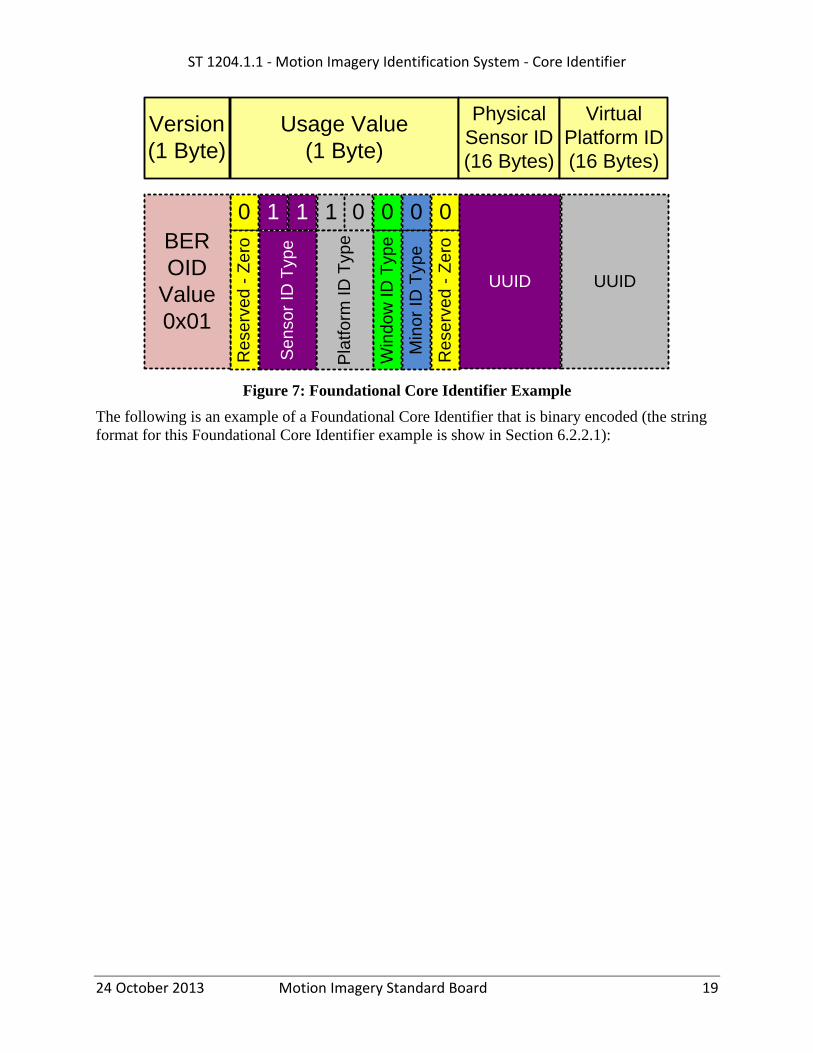
Figure 7 illustrates an example of a Foundational Core ID Binary Value. The top row shows a
Version value byte and Usage Value byte, followed by a Physical Sensor ID and then a Virtual
Platform ID. The second row of the figure illustrates the values that would be sent. The version
is set to 0x01 for the first version of this document. The Usage Value Byte’s bits’ are set as
follows (left to right): bit 7 is reserved and set to zero; bit 6 and 5 are both one to indicate a
Physical Sensor ID (see Table 2) ; bit 4 and 3 are set to one and zero, respectively, to indicate a
Virtual Platform ID (see Table 2); bit 2 is set to zero to indicate the that a Window ID is NOT
included; bit 1 is set to zero to indicate that a Minor ID is NOT included; bit 0 is reserved and
set to zero. The Sensor and Platform IDs are blocks of binary UUID values.
ST 1204.1.1 - Motion Imagery Identification System - Core Identifier
24 October 2013 Motion Imagery Standard Board 19
Figure 7: Foundational Core Identifier Example
The following is an example of a Foundational Core Identifier that is binary encoded (the string
format for this Foundational Core Identifier example is show in Section 6.2.2.1):
Usage Value
(1 Byte)
Physical
Sensor ID
(16 Bytes)
Virtual
Platform ID
(16 Bytes)
0 1 1 0 0 0 0
UUID UUID
Re
se
rve
d -
Ze
ro
Pla
tfo
rm ID
Typ
e
Win
do
w ID
Typ
e
Min
or
ID T
yp
e
Re
se
rve
d -
Ze
ro
1
Se
nso
r ID
Typ
e
Version
(1 Byte)
BER
OID
Value
0x01

ST 1204.1.1 - Motion Imagery Identification System - Core Identifier
24 October 2013 Motion Imagery Standard Board 20
Raw Hex Values of Binary Format Example
0170 F592 F023 7336 4AF8 AA91 62C0 0F2E B2DA 16B7 4341 0008 41A0
BE36 5B5A B96A 3645
Table 6: Explanation of Binary Format Hex Example
Version Usage Value Byte UUID - 1 UUID - 2
Hex
01 70
F592 F023
7336 4AF8
AA91 62C0
0F2E B2DA
16B7 4341
0008 41A0
BE36 5B5A
B96A 3645
Mea
nin
g
Version
1
Bit 0 1 1 1 0 0 0 0 Physical Sensor
ID
(UUID)
Virtual
Platform ID
(UUID)
Bit
Mea
nin
g
Res
erved
(A
lway
s 0)
11 I
ndic
ates
that
the
firs
t U
UID
is
a
Sen
sor
ID a
nd i
t’s
a P
hysi
cal
ID
10 I
ndic
ates
that
the
seco
nd
UU
ID i
s a
Pla
tform
ID
and i
t’s
a V
irtu
al I
D
0 I
ndic
ates
no W
indow
ID
incl
uded
0 I
ndic
ates
no M
ino
r ID
incl
uded
Res
erved
(A
lway
s 0)
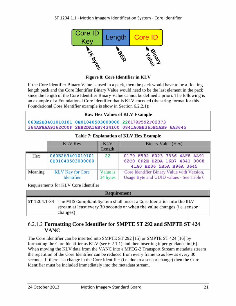
Formatting Core Identifier as KLV
The Core Identifier Binary Value can be used directly in KLV (see [10]) constructs including a
stand-alone value, sets and packs. As a stand-alone value the Core Identifier is prefixed by a key
and BER length value, as shown in Figure 8. The Key for a stand-alone value is 0x060E-2B34-
0101-0101-0E01-0405-0300-0000 (CRC 30280) and the normative Symbol name is “core_id”.
ST 1204.1.1 - Motion Imagery Identification System - Core Identifier
24 October 2013 Motion Imagery Standard Board 21
Figure 8: Core Identifier in KLV
If the Core Identifier Binary Value is used in a pack, then the pack would have to be a floating
length pack and the Core Identifier Binary Value would need to be the last element in the pack
since the length of the Core Identifier Binary Value cannot be defined a priori. The following is
an example of a Foundational Core Identifier that is KLV encoded (the string format for this
Foundational Core Identifier example is show in Section 6.2.2.1):
Raw Hex Values of KLV Example
060E2B3401010101 0E01040503000000 220170F592F02373 364AF8AA9162C00F 2EB2DA16B7434100 0841A0BE365B5AB9 6A3645
Table 7: Explanation of KLV Hex Example
KLV Key KLV
Length
Binary Value (Hex)
Hex 060E2B3401010101
0E01040503000000
22 0170 F592 F023 7336 4AF8 AA91
62C0 0F2E B2DA 16B7 4341 0008
41A0 BE36 5B5A B96A 3645
Meaning KLV Key for Core
Identifier
Value is
34 bytes
Core Identifier Binary Value with Version,
Usage Byte and UUID values - See Table 6
Requirements for KLV Core Identifier
Requirement
ST 1204.1-34 The MIIS Compliant System shall insert a Core Identifier into the KLV stream at least every 30 seconds or when the value changes (i.e. sensor changes)
Formatting Core Identifier for SMPTE ST 292 and SMPTE ST 424
VANC
The Core Identifier can be inserted into SMPTE ST 292 [15] or SMPTE ST 424 [16] by
formatting the Core Identifier as KLV (see 6.2.1.1) and then inserting it per guidance in [6].
When moving the KLV data from the VANC into a MPEG-2 Transport Stream metadata stream
the repetition of the Core Identifier can be reduced from every frame to as low as every 30
seconds. If there is a change in the Core Identifier (i.e. due to a sensor change) then the Core
Identifier must be included immediately into the metadata stream.
Core ID
KeyLength
16 b
yte
s
BE
R
Bin
ary
Valu
e
Core ID

ST 1204.1.1 - Motion Imagery Identification System - Core Identifier
24 October 2013 Motion Imagery Standard Board 22
Requirement
ST 1204.1-35 When a MIIS Compliant Sensor uses SMPTE STD 292 the Core Identifier shall be inserted into the VANC data space of every video frame according to MISB ST 0605[6].
ST 1204.1-36 When a MIIS Compliant Sensor uses SMPTE STD 424 the Core Identifier shall be inserted into the VANC data space of every video frame according to MISB ST 0605[6].
ST 1204.1-37 When Core Identifiers from the VANC data space are moved to a MPEG2 Transport Stream's metadata stream and the Core Identifier changes the Core Identifier shall be immediately inserted into the resulting metadata stream.
ST 1204.1-38 When Core Identifiers from the VANC data space are moved to a MPEG2 Transport Stream's metadata stream and the Core Identifier does not change the Core Identifier shall be repeated at least every 30 seconds in the resulting metadata stream.
6.2.2 Textual Formats
Textual Formats are used to provide a human readable Core Identifier Value for end users. The
Core Identifier Text Format (defined in the next section) is the format that is used by the Core
Identifier XML Format.
Core Identifier Text Format
When communicating Core Identifiers via text, the format defined below is used to aid in human
readability and data re-entry. When displaying or printing a Core Identifier for a user it is
recommended to use this format to promote consistency and reduce data entry error.
In accordance with [17], to aid in readability and reduce entry mistakes the format separates the
Core Identifier value into groups of hex digits with each group a maximum of four hex
characters long. Each group is separated by a separator character either a colon, ‘:’, dash, ‘-‘, or
slash,’/’, depending on the context of the group. The four character grouping structure includes
grouping the values for the embedded UUID components of the Core Identifier. This UUID
format is slightly different than the canonical UUID format; however to convert an embedded
UUID into the UUID Hexadecimal Representation ([2] section 6.4) the first and last two
separator characters are removed. Additionally a check value is added to enable systems to
validate if a user has entered or copied a value correctly. Table 8 describes the mapping between
the Core Identifier EBNF to Core Identifier Text Format:

ST 1204.1.1 - Motion Imagery Identification System - Core Identifier
24 October 2013 Motion Imagery Standard Board 23
Table 8: Core Identifier EBNF to Core Identifier Text Format Mapping
EBNF Textual Construct
Core
Identifier
Single line of characters which is the combination of Usage Value and
Foundational Core ID or Minor Core ID values as shown in the rest of this table.
Version Version is a Hex Value of the version number.
Usage Value Usage Value is a Hex Value of the information shown in Table 5. The Usage
Value Data is followed by a colon character, ‘:’.
FCID Combination of Sensor ID, Platform ID and/or Window ID with each value
separated by a slash character, ‘/’. The order of the Sensor ID, Platform ID and
Window ID is important and should follow the EBNF in Section 6.1. After the
last ID a colon character, ‘:’ is added.
Sensor ID UUID String Value
Platform ID UUID String Value
Window ID UUID String Value
MCID UUID String Value
UUID
String Value
39 character value composed of: hex value of the UUID, plus separator characters
(after every four hex characters a dash, ‘-‘, is inserted) E.g.: 0102-0304-0506-
0708-090A-0B0C-0D0E-0F10.
Other Note After the complete string of hex characters a check hex value is appended. Note
the check character validates only the hex digits, not the separator characters. The
check value algorithm is described in Appendix B.
Below are short summaries for FMIC and MCID, respectively:
VersionUsageValue:SensorID/PlatformID/WindowID:CheckValue
VersionUsageValue:MCID:CheckValue
The following is an example of a Foundational Core Identifier that is text formatted along with a
table explaining the values:

ST 1204.1.1 - Motion Imagery Identification System - Core Identifier
24 October 2013 Motion Imagery Standard Board 24
Example Core Identifier Text Value
0170:F592-F023-7336-4AF8-AA91-62C0-0F2E-B2DA/16B7-4341-0008-41A0-BE36-5B5A-B96A-3645:D3
Table 9: Explanation of Core Identifier Text Example
Version Usage Value
Byte
Colo
n UUID-1
Sla
sh UUID-2
Colo
n Check
Value
Hex
01 70 : F592-F023-
7336-4AF8-
AA91-62C0-
0F2E-B2DA
/ 16B7-4341-
0008-41A0-
BE36-5B5A-
B96A-3645
: D3
Mea
nin
g Version
1
Same as Usage
Value Byte in
Table 6
Sep
arat
or Physical Sensor
ID
Sep
arat
or Virtual
Platform ID
Sep
arat
or Check
Value for
Hex
characters
Note: If a UUID value is extracted from the string format it can converted to the UUID
Hexadecimal Representation ([2] section 6.4) by removing the first and last two separator
characters (i.e. dashes). For example:
ST 1204 Format 0102-0304-0506-0708-090A-0B0C-0D0E-0F10
UUID Hexadecimal Representation 01020304-0506-0708-090A-0B0C0D0E0F10
Core Identifier in XML
The XML schema in Listing 1 is used to format the Core Identifier as XML. The Core Identifier
Text Format (see Section 6.2.2.1) is inserted with the MiisCoreId XML tag and the CoreIdType
provides validation of the format of the Identifier.

ST 1204.1.1 - Motion Imagery Identification System - Core Identifier
24 October 2013 Motion Imagery Standard Board 25
Listing 1 - Core Identifier XML Schema
Listing 2 shows an example of the XML generated from the Listing 1 schema for the Core
Identifier.
Listing 2 - XML Example of Core Identifier
Requirement
ST 1204.1-39 When transmitting a Core Identifier within XML, the Core Identifier XML Format shall be used.
7 Unique Identifier for Frames
To generate a unique identifier for a motion imagery frame the Core Identifier is combined with
the MISB ST 0604 [8] MISPmicrosecond time stamp. When a Foundational Core Identifier is
used this technique provides a unique identifier for every frame across all motion imagery data
sources. Table 10 illustrates and example of a motion imagery file where each frame’s identifier
is created from a Core ID + 0604 Timestamp:
<?xml version="1.0" encoding="UTF-8"?>
<xs:schema xmlns:xs="http://www.w3.org/2001/XMLSchema"
targetNamespace="http://www.nga.gov/MiisSchema"
xmlns:tns="http://www.nga.gov/MiisSchema"
elementFormDefault="qualified">
<xs:element name="MiisCoreId" type="tns:CoreIdType" />
<xs:simpleType name="CoreIdType" >
<xs:restriction base="xs:string">
<xs:pattern
value="[A-F0-9]{4}:(([A-F0-9]{4}-){7}[A-F0-9]{4})(/([A-
F0-9]{4}-){7}[A-F0-9]{4})?(/([A-F0-9]{4}-){7}[A-F0-9]{4})?:[A-
F0-9]{2}">
</xs:pattern>
</xs:restriction>
</xs:simpleType>
</xs:schema>
<?xml version="1.0" encoding="UTF-8" standalone="yes"?> <MiisCoreId xmlns="http://www.nga.gov/MiisSchema"> 0170:F592-F023-7336-4AF8-AA91-62C0-0F2E-B2DA/16B7-4341-0008-41A0-BE36-5B5A-B96A-3645:D3 </MiisCoreId>

ST 1204.1.1 - Motion Imagery Identification System - Core Identifier
24 October 2013 Motion Imagery Standard Board 26
Table 10: Unique Identifier for Motion Imagery Frames
Frame Core Id 0604 Timestamp
Frame 1
0170:F592-F023-7336-4AF8-AA91-62C0-0F2E-B2DA/16B7-4341-0008-41A0-BE36-5B5A-B96A-
3645:D3
2012-08-
20T13:23:13.134000
Frame 2
0170:F592-F023-7336-4AF8-AA91-62C0-0F2E-B2DA/16B7-4341-0008-41A0-BE36-5B5A-B96A-
3645:D3
2012-08-
20T13:23:13.167000
Since the Foundational Identifier is unique across all platforms and the timestamp provides a
unique id for each frame, the combination of the two provides a universally unique frame id for
any system.
8 Generating Enterprise UUID’s from Core Identifiers
Core Identifiers will be used for many different purposes, such as the identifier within enterprise
systems. The Core Identifier is constructed from one or more UUIDs so each UUID maps
directly in to the enterprise standards [9]. The Core Identifier can be either an FCID or MCID
each of which has their own technique for generating enterprise IDs. For an MCID the enterprise
ID is simply constructed from the UUID within the MCID. The MCID based enterprise ID does
provide some functionality; however, it is limited in scope to where the MCID was inserted into
the stream - see Appendix C for a discussion on this issue.
For FCIDs up to three enterprise identifiers can be constructed: (1) an identifier from the FCID’s
Sensor ID, (2) an identifier from the FCID’s Platform ID and (3) an identifier from the FCID’s
Window ID. These three enterprise identifiers can be used independently or together. Since the
Core ID can change over time, combining the three identifiers into one UUID is not used as a
method for Enterprise UUIDs.
See Appendix C and Appendix D for more information on the configurations of various systems
and how they relate to the resulting identifiers.
9 Identification Retention
Motion Imagery is manipulated by many systems as it travels from the sensor to the users.
During these manipulations it is important to maintain the identification throughout all
processing. The end result of Motion Imagery exploitation is to generate products. In order to
ensure traceability back to the original source the identification information needs to be retained
with the product.

ST 1204.1.1 - Motion Imagery Identification System - Core Identifier
24 October 2013 Motion Imagery Standard Board 27
Requirement
ST 1204.1-40 When a system or software manipulates, transcodes, extracts or augments the Motion Imagery, it shall preserve the Core Identifier in both the altered motion imagery and metadata.
ST 1204.1-41 All Motion Imagery products generated from the Motion Imagery shall retain the Core Identifier from the source Motion Imagery.
10 Compliance Levels
Table 11 and Table 12 list the compliancy levels for the MIIS Core Identifier. Table 11 lists the
compliancy levels for systems that are NOT extracting windows from the Motion Imagery data.
Table 12 lists the compliancy levels for systems that do extract a window from the Motion
Imagery Data. The compliancy levels are lowered when systems are extracting a window from
Motion Imagery Data and the system is NOT putting a window Identifier into the Core Identifier
(levels 17 down to 2).
With either table the higher the number the better the compliancy the overall system has to this
Standard. The goal for all systems is to achieve a compliancy level of 32.
Table 11: Compliance Levels for Non-Windowing Systems
Level Sensor Platform
32 Physical Physical
31 Physical Virtual
30 Physical Managed
29 Virtual Physical
28 Virtual Virtual
27 Virtual Managed
26 Managed Physical
25 Managed Virtual
24 Managed Managed
23 Physical None
22 Virtual None
21 Managed None
20 None Physical
19 None Virtual
18 None Managed
17-2 Window Based Levels -
See Table 12
1 Minor Identifier
0 No Identification

ST 1204.1.1 - Motion Imagery Identification System - Core Identifier
24 October 2013 Motion Imagery Standard Board 28
Table 12: Compliance Levels for Windowing Systems
Level Sensor Platform Window
ID
Comment
32 Physical Physical Yes Motion Imagery from Window
31 Physical Virtual Yes Motion Imagery from Window
30 Physical Managed Yes Motion Imagery from Window
29 Virtual Physical Yes Motion Imagery from Window
28 Virtual Virtual Yes Motion Imagery from Window
27 Virtual Managed Yes Motion Imagery from Window
26 Managed Physical Yes Motion Imagery from Window
25 Managed Virtual Yes Motion Imagery from Window
24 Managed Managed Yes Motion Imagery from Window
23 Physical None Yes Motion Imagery from Window
22 Virtual None Yes Motion Imagery from Window
21 Managed None Yes Motion Imagery from Window
20 None Physical Yes Motion Imagery from Window
19 None Virtual Yes Motion Imagery from Window
18 None Managed Yes Motion Imagery from Window
17 None None Yes Motion Imagery from Window
16 Physical Physical No Motion Imagery is from a Window but no Window
ID
15 Physical Virtual No Motion Imagery is from a Window but no Window
ID
14 Physical Managed No Motion Imagery is from a Window but no Window
ID
13 Virtual Physical No Motion Imagery is from a Window but no Window
ID
12 Virtual Virtual No Motion Imagery is from a Window but no Window
ID
11 Virtual Managed No Motion Imagery is from a Window but no Window
ID
10 Managed Physical No Motion Imagery is from a Window but no Window
ID
9 Managed Virtual No Motion Imagery is from a Window but no Window
ID
8 Managed Managed No Motion Imagery is from a Window but no Window
ID
7 Physical None No Motion Imagery is from a Window but no Window
ID
6 Virtual None No Motion Imagery is from a Window but no Window
ID
5 Managed None No Motion Imagery is from a Window but no Window
ID
4 None Physical No Motion Imagery is from a Window but no Window
ID

ST 1204.1.1 - Motion Imagery Identification System - Core Identifier
24 October 2013 Motion Imagery Standard Board 29
3 None Virtual No Motion Imagery is from a Window but no Window
ID
2 None Managed No Motion Imagery is from a Window but no Window
ID

ST 1204.1.1 - Motion Imagery Identification System - Core Identifier
24 October 2013 Motion Imagery Standard Board 30
Appendix A UUID Generation - Normative
A Universal Unique IDentifiers (UUID) can be generated using multiple techniques as discussed
in [2] and [3]. NGA has written a Recommended Practice [5] that discusses which UUID
versions can be used.
Version 1 is generated using the Ethernet MAC address and system clock; version 4 is generated
from a random number generator; version 5 is generated by SHA hash coding some textual
information.
This Standard recommends, when possible, that UUID’s be constructed from unique device
information through the version 5 SHA hash coding process, for example combine manufacturer
name, model number, serial number and use the SHA hash function to generated the UUID.
If version 4 is used, ensure that a good cryptographic random number generator is provided; refer
to [7] for information on random number generation.
Version 1 is not recommended and can be used only if the device that is being identified has a
MAC address.
Sometimes it is necessary to form a new UUID from two or more existing UUID’s. The
following technique is used to enable the possibility of reconstruction of a UUID from the source
UUIDs. To combine the UUID’s each of the UUID’s are converted into the hexadecimal format
defined in Section 6.4 of [2] in uppercase (e.g. F81D4FAE-7DEC-11D0-A765-
00A0C91E6BF6), they are then appended together (without separator characters) and the version
5 hash code algorithm is performed.
Requirement
ST 1204.1-42 UUIDs shall be generated using only UUID versions 1, 4 and 5 as stated in [5]
ST 1204.1-43 The creator of the UUID shall insure that the information (or combination of information) used as the hash source is unique for every device
ST 1204.1-44 The null MAC address shall not be used for UUID generation
Appendix B Check Value
There are many cases when data is copied from one system to another, and when data is
transferred between computers, via networks, there are many checks to validate if the data was
transferred correctly. There are times when humans need to transfer data from one system to
another and the only, or most expedient, means for doing the transfer is to type the data into a
system. To validate if a series of characters has been transferred correctly a check value can be
computed and added to the original value. Receivers of the data will be able to compute the same
check value and compare it to the original check value to see if they are the same. If the values
are the same then the data was most likely transmitted correctly (these checks are not perfect);
otherwise there was an error in the transmission. The method used, in this Standard, for
computing the check value is based on [13], which is for hexadecimal values only. This
technique is specifically designed to detect the common problems that occur when humans enter

ST 1204.1.1 - Motion Imagery Identification System - Core Identifier
24 October 2013 Motion Imagery Standard Board 31
data into systems, which is different than other techniques such as check sums and CRC’s that
are designed for burst errors related to transmission issues.
The algorithm in [13] computes a four-bit check digit based on a set of permutations of the hex
digits. Two adjustments have been made to this algorithm. First, in [13] the check value is
computed by inverting the “sum” of the permutations. This step is not needed, so the check value
for this Standard is just the “sum”. The second adjustment is to execute the algorithm with the
standard permutations, then use a second set of permutations and re-run the algorithm a second
time to compute a second four-bit check digit; both check digits are combined into a single byte
as the check value. The extra run provides a better check value and uses a full byte for the check
value. To improve efficiency both check digits are computed in a single loop through the hex
values.
Notation:
^ is xor
Hex digit H is composed of 4 bits [a,b,c,d]
p (lower case) is a permutation of a hex value, noted p(H) = p ([a,b,c,d])
pj(H) is multiple permutations of hex value H. Example: p2(H) = p(p(H))
The algorithm:
1. Initialize (one time operation)
a. Create permutation table P of all 16 hex values using bit manipulation method
from [13] so a single permutation of H is p(H) = p([a,b,c,d]) = [a^b,c,d,a].
b. Create permutation table q of all 16 values using inverse bit manipulation method
(not in [13]) so q([a,b,c,d]) = [d,a^d,b,c]
2. Compute Check Value
a. Loop k through hex values in hex string H
i. CheckVal_p = CheckVal_p ^ pk(H)
ii. CheckVal_q = CheckVal_q ^ qk(H)
b. CheckVal_byte = Shift Left 4 bits (CheckVal_p ) or’ed with (CheckVal_q)
Please see the reference code for complete details of the algorithm.
Appendix C Core Identifier Background
Figure 9 shows a high level view of data flow from a single motion imagery data source (1)
being distributed to a group of users (4). In this example there are two primary routes for how the
motion imagery is distributed to end users, either a Direct Route or via a Control Station Route
(2). With the Direct Route the motion imagery is distributed to end user (A) without passing
through the Ground Control Station (GCS) or any other nodes. In this example there is only one
Direct Route end user but there could be a large set of Direct Route end users. With the Control
Station Route the motion imagery passes through the control station and is sent to a distribution
network (3) where it is routed to the end users (B), (C), (D) and (E).

ST 1204.1.1 - Motion Imagery Identification System - Core Identifier
24 October 2013 Motion Imagery Standard Board 32
Figure 9: Motion Imagery Data Flow Scenario
Identification information can be inserted into the motion imagery data at four points: (1) the
source, (2) the GCS, (3) the distribution cloud or at (4) the end user sites.The optimal point to
insert identification information is at the source (1), because the identifier(s) will be available
(i.e. flow down) to all the components of the overall system (i.e., distribution network and end
users sites). If identifiers have not been inserted at the source then the next best place to insert
identification is within the GCS (2). If the identifiers have not been inserted in the GCS then the
next possible insert point is within the distribution network (2); however, the usefulness of this
varies depending on which “part” of the network the identifiers are inserted. If the identifiers are
inserted immediately after receiving the motion imagery data (i.e., right after the GCS (2)) then
this provides a consistent identifier for all downstream dissemination. If the identifiers are
inserted just before leaving the distribution network, then there is no guarantee that all copies of
the motion imagery data leaving the network will have the same identifiers, which, does not
provide the consistency desired. If neither the source (1) nor GCS (2) nor distribution network
(2) inserts an identifier, then the user sites (3) can insert their own identifiers; however, each site
would have different identifiers unless there is some extra backchannel coordination performed
between sites.
Identification coverage is defined as the percentage of users that are able to access or use a
common identifier. The goal is to provide an identifier that has 100% coverage so that it is
available to all users of the motion imagery data. As an example the following table shows the
coverage based on where the identifiers are inserted into the motion imagery data.
Exploitation Node
Distribution Node
GCS
OCONUS CONUS
Ground
Unit
Ground
Unit
Theater
Exploit
National
Exploit
National
Historical
GCS
(1)
(2)
(3)
(4)
Dire
ct R
oute
(A) (B) (C) (D) (E)
Distribution
Network
Control Station
Route
Key

ST 1204.1.1 - Motion Imagery Identification System - Core Identifier
24 October 2013 Motion Imagery Standard Board 33
Table 13: Coverage Example for Figure 9
Insertion
Point
Sites using the same ID Coverage Comments
A B C D E
Source (1) Y Y Y Y Y 5/5 =
100%
All users using the same ID, this provides
perfect coverage and is the goal of this
standard.
GCS (2) N Y Y Y Y 4/5 =
80%
A majority of users would be receiving
the identification information.
CONUS
Node N N N Y Y
2/5 =
40%
Coordination between CONUS and
OCONUS users is reduced; alternate
methods would have to be used.
User Site (D) N N N N Y 1/5 =
20%
Only users at site (D) would have a
common ID so the id is only affective in
the one location.
Figure 9 also can be used to illustrate a problem with the value to insert as the identifier. As
discussed previously, if the identifier is not created at the source then the identifier cannot
provide 100% or full coverage. When a “downstream” component (e.g. GCS) inserts an
identifier it cannot provide full coverage which means that some users of the system will have an
identifier and some will not. For the parts of the system that do not have identifiers, other
“downstream” components could insert different identifiers. For example, in Figure 9, if the
OCONUS component inserts an identifier independently from the CONUS component, each
would be inserting a different identifier and then theater exploiters (or systems) and national
exploiters (or systems) would not be able to recognize that they may be working on the same
stream. This issue promotes the need for a method to tell how good the identifier is or the quality
of the identifier. When identifiers are inserted at the source (1) then the quality is high; likewise
when identifiers are inserted at the GCS (2) the quality is lower; and if an identifier is inserted
with the network distribution or user sites then the quality is minimal. Another factor that affects
the quality is what identification information is inserted into the motion imagery.
At the motion imagery source there are several options for providing a unique identifier.
Appendix D illustrates a couple of source architectures. It is clear that there is no one single
piece of information that can be used as an identifier, so a collection of identifiers is used as the
source identifier. Ideally, every device that motion imagery passes through should add
identifying information to the stream creating an “ID history”; however this is impractical, since
it would require that every device would have to de-multiplex, update and re-multiplex the
motion imagery stream.
This standard defines a minimum set of elements such that the identifiers still provide uniqueness
and a basis for augmentation data. The resulting minimum identifier is a sensor identifier,
combined with a platform identifier; these two pieces of information uniquely identify a source.
However, when a sensor system, such as a WAMI sensor, produces one or more “virtual”
windows from a motion imagery source, an additional identifier must be added called a window
identifier. These two or three pieces of identifying information form the Foundational Core
Identifier. Since the Foundational Core Identifier is generated with known information from the

ST 1204.1.1 - Motion Imagery Identification System - Core Identifier
24 October 2013 Motion Imagery Standard Board 34
platform and sensor the only insertion points can be either the Source (1) or the Control Station
(2). This enables the quality of the Foundational Core Identifier to be high. All other insertion
points cannot positively ensure that the correct sensor/platform identifier would be used so when
inserting an identifier at these insertion points a random Universal Unique Identifier is used
(UUID). This type of identifier provides minimal quality, so it is called a Minor Core Identifier.
The Foundational Core Identifier can change over time within a mission. For example when the
sensor source is changed (i.e. EO to IR) the sensor component of the Identifier will change;
however, the platform component of the identifier remains the same. It is up to the receivers of
the data to interpret these values and determine how to process and use them. The Foundational
Core Identifier along with the MISB ST 0604 timestamp will enable frame-by-frame unique
identifiers that can be used as a basis for augmented identifiers.
In summary, the only condition where 100% identification coverage can be guaranteed is when
the identifiers are inserted at the Source or Control Station. Unfortunately, currently deployed
systems do not have this capability, so downstream or minimal identification methods have to be
used until such time that the platforms/sensors provide source based identification information
(i.e. Foundational Core Identifiers).
Appendix D Architecture Overview of Platform Sensor
This appendix describes a general architecture for motion imagery systems along with several
examples of the general architecture.
Figure 10 shows a generic architecture to support a single sensor and the data flow through the
architecture. This figure shows four different types of items: data producers (blue), data
processors/movers (yellow), data storage (orange) and users (green). Each item is described in
Table 14.
Figure 10: Generic Motion Imagery Architecture
Sen
Plat
OB
ProTx Rx Dist
RT
User
UserLib
Proc
On Board Platform

ST 1204.1.1 - Motion Imagery Identification System - Core Identifier
24 October 2013 Motion Imagery Standard Board 35
Table 14: Architecture Components
Item Name Description
Sen Sensor Collects Motion Imagery (including metadata) from scene
Plat Platform Physically supports the sensor, produces metadata (e.g. orientation, etc.)
OBPro On Board
Processing
Processes Motion Imagery and Metadata onboard the platform.
Processing examples: Encoder, Multiplexor, Switching, on board
storage, etc.
Tx Transmitter Transmits Motion Imagery to one or more Receivers – can include
encoding and/or transrating of motion imagery.
Rx Receiver Receives transmitted motion imagery – can include multiplexing
additional metadata into motion imagery
Dist Distribution Dissemination of Motion Imagery through one or more networks. Can
include switches, guards, SATCOMs, etc.
Lib Library Library storage of Motion Imagery data
Proc Processing Real-time and Post-processing of Motion Imagery data
RTUser Real Time
User
User exploiting Motion Imagery during mission. Operations include
annotation, clipping, etc.
User User Non-Real time exploiting motion imagery mission
Motion Imagery systems contain at least one sensor, but other items in this list may not be used.
For example, a hand-held camera has a sensor and on-board storage, the user can view the video
directly on the back of the camera system. In this example the Tx, Rx, Dist, Lib, Proc are not
needed. Another example is an airborne system that uses all items in the list/diagram. This
generic architecture can be applied to all Motion Imagery systems use in Air, Ground, Water and
Space.
To understand the complexities of the identification problem a couple of detailed examples are
described below. Figure 11 illustrates a UAS architecture/data flow which uses two sensors and
an A/B switch to determine which sensors data is transmitted to the receivers. Additionally, the
selected stream is encoded with two different encoders, one for SATCOM transmission and one
for line–of-site (LOS) transmission. Each encoder may be operating using different data rates
and qualities.
Figure 11: UAS Dual Sensor with Dual Encoder
Sen
Plat
Tx Rx Dist
RT
User
UserLib
On Board Platform
Sen
TxRT
UserRx
A/B
Encode
Encode
RT
User
UserLib
OB Pro
Omni-
Directional
SATCOM

ST 1204.1.1 - Motion Imagery Identification System - Core Identifier
24 October 2013 Motion Imagery Standard Board 36
With this architecture inserting an identifier before the encoders is the only way to ensure that
the SATCOM users and LOS users both receive the same identifier. In this example a platform
unique identifier would solve the identification problem since the system is focused on one
mission; however, other examples show that this is not always the case.
Figure 12 illustrates an example of many sensors’ data being switched (as needed) to a
transmitter. Each sensor could be used for different missions or user needs.
Figure 12: Multi-Sensor Multi-Transmission
In this example the Platform ID would be insufficient and a more appropriate identifier would be
to use a Sensor ID.
Plat
Tx Rx
Dist
RT
User
UserLib
On Board Platform
Tx Rx
MxN
Switch
RT
User
UserLib
Sen
Sen
Sen
Sen
Tx
OB Pro
Rx