Embed Size (px)
Citation preview

Mot
herb
oard
P9D WS

ii
E8141
First EditionMay 2013
Copyright © 2013 ASUSTeK COMPUTER INC. All Rights Reserved.No part of this manual, including the products and software described in it, may be reproduced, transmitted, transcribed, stored in a retrieval system, or translated into any language in any form or by any means, except documentation kept by the purchaser for backup purposes, without the express written permission of ASUSTeK COMPUTER INC. (“ASUS”).Product warranty or service will not be extended if: (1) the product is repaired, modified or altered, unless such repair, modification of alteration is authorized in writing by ASUS; or (2) the serial number of the product is defaced or missing.ASUS PROVIDES THIS MANUAL “AS IS” WITHOUT WARRANTY OF ANY KIND, EITHER EXPRESS OR IMPLIED, INCLUDING BUT NOT LIMITED TO THE IMPLIED WARRANTIES OR CONDITIONS OF MERCHANTABILITY OR FITNESS FOR A PARTICULAR PURPOSE. IN NO EVENT SHALL ASUS, ITS DIRECTORS, OFFICERS, EMPLOYEES OR AGENTS BE LIABLE FOR ANY INDIRECT, SPECIAL, INCIDENTAL, OR CONSEQUENTIAL DAMAGES (INCLUDING DAMAGES FOR LOSS OF PROFITS, LOSS OF BUSINESS, LOSS OF USE OR DATA, INTERRUPTION OF BUSINESS AND THE LIKE), EVEN IF ASUS HAS BEEN ADVISED OF THE POSSIBILITY OF SUCH DAMAGES ARISING FROM ANY DEFECT OR ERROR IN THIS MANUAL OR PRODUCT.SPECIFICATIONS AND INFORMATION CONTAINED IN THIS MANUAL ARE FURNISHED FOR INFORMATIONAL USE ONLY, AND ARE SUBJECT TO CHANGE AT ANY TIME WITHOUT NOTICE, AND SHOULD NOT BE CONSTRUED AS A COMMITMENT BY ASUS. ASUS ASSUMES NO RESPONSIBILITY OR LIABILITY FOR ANY ERRORS OR INACCURACIES THAT MAY APPEAR IN THIS MANUAL, INCLUDING THE PRODUCTS AND SOFTWARE DESCRIBED IN IT.Products and corporate names appearing in this manual may or may not be registered trademarks or copyrights of their respective companies, and are used only for identification or explanation and to the owners’ benefit, without intent to infringe.
Offer to Provide Source Code of Certain SoftwareThis product contains copyrighted software that is licensed under the General Public License (“GPL”), under the Lesser General Public License Version (“LGPL”) and/or other Free Open Source Software Licenses. Such software in this product is distributed without any warranty to the extent permitted by the applicable law. Copies of these licenses are included in this product.Where the applicable license entitles you to the source code of such software and/or other additional data, you may obtain it for a period of three years after our last shipment of the product, either(1) for free by downloading it from http://support.asus.com/downloador(2) for the cost of reproduction and shipment, which is dependent on the preferred carrier and the location where you want to have it shipped to, by sending a request to:
ASUSTeK Computer Inc.Legal Compliance Dept.15 Li Te Rd.,Beitou, Taipei 112Taiwan
In your request please provide the name, model number and version, as stated in the About Box of the product for which you wish to obtain the corresponding source code and your contact details so that we can coordinate the terms and cost of shipment with you.The source code will be distributed WITHOUT ANY WARRANTY and licensed under the same license as the corresponding binary/object code.This offer is valid to anyone in receipt of this information.ASUSTeK is eager to duly provide complete source code as required under various Free Open Source Software licenses. If however you encounter any problems in obtaining the full corresponding source code we would be much obliged if you give us a notification to the email address [email protected], stating the product and describing the problem (please DO NOT send large attachments such as source code archives, etc. to this email address).

iii
ContentsNotices ....................................................................................................................... viSafety information ..................................................................................................... viiAbout this guide ....................................................................................................... viiiP9D WS specifications summary .............................................................................. x
Chapter 1: Product introduction1.1 Welcome! ....................................................................................................1-11.2 Package contents.......................................................................................1-11.3 Special features..........................................................................................1-2
1.3.1 Product highlights........................................................................ 1-21.3.2 ASUS Workstation Exclusive Features ....................................... 1-31.3.3 ASUS features ............................................................................ 1-4
Chapter 2: Hardware information2.1 Before you proceed ...................................................................................2-12.2 Motherboard overview ...............................................................................2-2
2.2.1 Motherboard layout ..................................................................... 2-22.2.2 Central Processing Unit (CPU) ................................................... 2-42.2.3 System memory .......................................................................... 2-52.2.4 Expansion slots ......................................................................... 2-112.2.5 Onboard buttons and switches.................................................. 2-132.2.6 Onboard LEDs ..........................................................................2-162.2.7 Jumper ......................................................................................2-212.2.8 Internal connectors.................................................................... 2-23
2.3 Building your computer system ............................................................. 2-342.3.1 Additional tools and components to build a PC system ............ 2-342.3.2 CPU installation.........................................................................2-352.3.3 CPU heatsink and fan assembly installation ............................. 2-372.3.4 DIMM installation....................................................................... 2-392.3.5 Motherboard installation ............................................................ 2-402.3.6 ATX Power connection .............................................................. 2-422.3.7 SATA device connection ............................................................ 2-432.3.8 Front I/O Connector .................................................................. 2-442.3.9 Expansion Card installation....................................................... 2-452.3.10 BIOS update utility .................................................................... 2-462.3.11 Rear panel connection .............................................................. 2-472.3.12 Audio I/O connections ............................................................... 2-48
2.4 Starting up for the first time .................................................................... 2-512.5 Turning off the computer .........................................................................2-51

iv
Contents
Chapter 3: BIOS setup3.1 Knowing BIOS ............................................................................................3-13.2 BIOS setup program ..................................................................................3-2
3.2.1 EZ Mode......................................................................................3-33.2.2 Advanced Mode .......................................................................... 3-4
3.3 My Favorites ...............................................................................................3-63.4 Main menu ..................................................................................................3-73.5 Ai Tweaker menu ........................................................................................3-93.6 Advanced menu .......................................................................................3-24
3.6.1 CPU Configuration .................................................................... 3-253.6.2 PCH Configuration .................................................................... 3-283.6.3 SATA Configuration ................................................................... 3-293.6.4 System Agent Configuration...................................................... 3-313.6.5 USB Configuration .................................................................... 3-333.6.6 Platform Misc Configuration ...................................................... 3-343.6.7 Onboard Devices Configuration ................................................ 3-353.6.8 APM ..........................................................................................3-373.6.9 Network Stack ...........................................................................3-38
3.7 Monitor menu ...........................................................................................3-393.8 Boot menu ................................................................................................3-423.9 Tools menu ...............................................................................................3-48
3.9.1 ASUS EZ Flash 2 Utility ............................................................ 3-483.9.2 ASUS O.C. Profile ..................................................................... 3-483.9.3 ASUS SPD Information ............................................................. 3-49
3.10 Exit menu ..................................................................................................3-503.11 Updating BIOS ..........................................................................................3-51
3.11.1 EZ Update .................................................................................3-513.11.2 ASUS EZ Flash 2 ...................................................................... 3-523.11.3 ASUS CrashFree BIOS 3 .......................................................... 3-533.11.4 ASUS BIOS Updater ................................................................. 3-54
Chapter 4: Software support4.1 Installing an operating system ................................................................. 4-14.2 Support DVD information .......................................................................... 4-1
4.2.1 Running the support DVD ........................................................... 4-14.2.2 Obtaining the software manuals.................................................. 4-2
4.3 Software information .................................................................................4-34.3.1 AI Suite 3.....................................................................................4-34.3.2 DIGI+ VRM ..................................................................................4-5

v
4.3.3 EPU .............................................................................................4-74.3.4 Fan Xpert 2 .................................................................................4-84.3.5 USB 3.0 Boost...........................................................................4-104.3.6 EZ Update ................................................................................. 4-114.3.7 Network iControl........................................................................ 4-124.3.8 System Information ................................................................... 4-144.3.9 USB BIOS Flashback ................................................................ 4-164.3.10 USB Charger+ ...........................................................................4-174.3.11 Audio configurations.................................................................. 4-18
Chapter 5: Multiple GPU technology support5.1 ATI® CrossFireX™ technology .................................................................. 5-1
5.1.1 Requirements ..............................................................................5-15.1.2 Before you begin ......................................................................... 5-1
Contents

vi
Notices
Federal Communications Commission StatementThis device complies with Part 15 of the FCC Rules. Operation is subject to the following two conditions:• This device may not cause harmful interference, and• This device must accept any interference received including interference that may cause
undesired operation.This equipment has been tested and found to comply with the limits for a Class B digital device, pursuant to Part 15 of the FCC Rules. These limits are designed to provide reasonable protection against harmful interference in a residential installation. This equipment generates, uses and can radiate radio frequency energy and, if not installed and used in accordance with manufacturer’s instructions, may cause harmful interference to radio communications. However, there is no guarantee that interference will not occur in a particular installation. If this equipment does cause harmful interference to radio or television reception, which can be determined by turning the equipment off and on, the user is encouraged to try to correct the interference by one or more of the following measures:
• Reorient or relocate the receiving antenna.• Increase the separation between the equipment and receiver.• Connect the equipment to an outlet on a circuit different from that to which the receiver is
connected.• Consult the dealer or an experienced radio/TV technician for help.
Canadian Department of Communications StatementThis digital apparatus does not exceed the Class B limits for radio noise emissions from digital apparatus set out in the Radio Interference Regulations of the Canadian Department of Communications.This class B digital apparatus complies with Canadian ICES-003.
The use of shielded cables for connection of the monitor to the graphics card is required to assure compliance with FCC regulations. Changes or modifications to this unit not expressly approved by the party responsible for compliance could void the user’s authority to operate this equipment.
REACHComplying with the REACH (Registration, Evaluation, Authorisation, and Restriction of Chemicals) regulatory framework, we published the chemical substances in our products at ASUS REACH website at http://csr.asus.com/english/REACH.htm.
DO NOT throw the motherboard in municipal waste. This product has been designed to enable proper reuse of parts and recycling. This symbol of the crossed out wheeled bin indicates that the product (electrical and electronic equipment) should not be placed in municipal waste. Check local regulations for disposal of electronic products.
DO NOT throw the mercury-containing button cell battery in municipal waste. This symbol of the crossed out wheeled bin indicates that the battery should not be placed in municipal waste.

vii
Safety information
Electrical safety• To prevent electrical shock hazard, disconnect the power cable from the electrical outlet
before relocating the system.• When adding or removing devices to or from the system, ensure that the power cables
for the devices are unplugged before the signal cables are connected. If possible, disconnect all power cables from the existing system before you add a device.
• Before connecting or removing signal cables from the motherboard, ensure that all power cables are unplugged.
• Seek professional assistance before using an adapter or extension cord. These devices could interrupt the grounding circuit.
• Ensure that your power supply is set to the correct voltage in your area. If you are not sure about the voltage of the electrical outlet you are using, contact your local power company.
• If the power supply is broken, do not try to fix it by yourself. Contact a qualified service technician or your retailer.
Operation safety• Before installing the motherboard and adding devices on it, carefully read all the manuals
that came with the package.• Before using the product, ensure all cables are correctly connected and the power
cables are not damaged. If you detect any damage, contact your dealer immediately.• To avoid short circuits, keep paper clips, screws, and staples away from connectors,
slots, sockets and circuitry.• Avoid dust, humidity, and temperature extremes. Do not place the product in any area
where it may become wet.• Place the product on a stable surface.• If you encounter technical problems with the product, contact a qualified service
technician or your retailer.

viii
About this guideThis user guide contains the information you need when installing and configuring the motherboard.
How this guide is organizedThis guide contains the following parts:
• Chapter 1: Product introductionThis chapter describes the features of the motherboard and the new technology it supports.
• Chapter 2: Hardware informationThis chapter lists the hardware setup procedures that you have to perform when installing system components. It includes description of the switches, jumpers, and connectors on the motherboard.
• Chapter 3: BIOS setupThis chapter tells how to change system settings through the BIOS Setup menus. Detailed descriptions of the BIOS parameters are also provided.
• Chapter 4: Software supportThis chapter describes the contents of the support DVD that comes with the motherboard package and the software.
• Chapter 5: Multiple GPU technology supportThis chapter describes how to install and configure multiple ATI® CrossFireX™ and NVIDIA® SLI™ graphics cards.
Where to find more informationRefer to the following sources for additional information and for product and software updates.
1. ASUS websitesThe ASUS website provides updated information on ASUS hardware and software products. Refer to the ASUS contact information.
2. Optional documentationYour product package may include optional documentation, such as warranty flyers, that may have been added by your dealer. These documents are not part of the standard package.

ix
Conventions used in this guideTo ensure that you perform certain tasks properly, take note of the following symbols used throughout this manual.
Typography
Bold text Indicates a menu or an item to select.
Italics Used to emphasize a word or a phrase.
<Key> Keys enclosed in the less-than and greater-than sign means that you must press the enclosed key.that you must press the enclosed key. Example: <Enter> means that you must press the Enter or Return key.Return key.
<Key1> + <Key2> + <Key3> If you must press two or more keys simultaneously, the key names are linked with a plus sign (+).
Example: <Ctrl> + <Alt> + <Del>
DANGER/WARNING: Information to prevent injury to yourself when trying to complete a task.
CAUTION: Information to prevent damage to the components when trying to complete a task.
IMPORTANT: Instructions that you MUST follow to complete a task.
NOTE: Tips and additional information to help you complete a task.

x
P9D WS specifications summary
CPU LGA1150 socket for 4th Gen Intel® Core™ i3 processorsLGA1150 socket for Intel® Xeon® E3-1200/ 12x5 v3 series processorSupports 22nm CPU* Supports Intel® Turbo Boost technology 2.0.** Refer to www.asus.com for Intel® CPU support list.
Chipset Intel® C226 Chipset
Memory 4 x DIMMs, max. 32GB, DDR3 1600 / 1333 MHz, ECC non-ECC, un-buffered memoryDual-channel architectureSupports Intel® Extreme Memory Profile (XMP)**Refer to www.asus.com or this user manual for the Memory QVL (Qualified Vendors Lidts)
Expansion slots
1 x PCIe 3.0 x16 (at x16 or x8)1 x PCIe 3.0 x16 (at x8 or x4)1 x PCIe 3.0 x16 (at x4)1 x PCIe 2.0 x16 (at x4)1 x PCIe 2.0 x1 (at x1)2 x PCI
Graphic Integrated Graphics ProcessorMulti-VGA output support: DVI-I/HDMI/Displayport portsSupports DVI with max. resolution 1920 x 1200 at 60HzSupports HDMI with max. resolution 4096 x 2160 at 24HzSupports Displayport with max. resolution 3200 x 2000 at 60HzMaximum shared memory of 1GB Supports Intel® HD Graphics, InTru™ 3D, Quick Sync Video, Clear Video HD Technology, Insider™
Multi-GPU support
Supports ATI® Quad-GPU CrossFireX™ Technology
Storage Intel® C226 Chipset:- 6 x SATA 6.0 Gb/s ports(yellow)- Intel® Rapid Storage Technology supports RAID 0, 1, 5, and 10
LAN 2*Intel® i210 GbE LAN- Support teaming function
USB Intel® C226 Chipset:- 4 x USB 3.0/ 2.0 ports (2 ports at mid-board, 2 ports at back panel)- 9 x USB 2.0/ 1.0 ports (5 ports at mid-board, 4 ports at back panel)
1394 1 x IEEE 1394a ports (1 port at min-board)Audio Realtek® ALC892 8-channel High Definition Audio CODEC
- BD audio layer content protection- Supports Jack-Detection, Multi-streaming and Front Panel Jack-Retasking- Optical S/PDIF out ports at back I/O
(continued on the next page)

xi
P9D WS specifications summary
ASUS Unique Features
ASUS Power Design- 8+2 Phase Power Design
ASUS EPU- EPU, EPU Switch
ASUS Exclusive Features- USB 3.0 Boost- Network iControl- MemOK!- AI Suite III- Anti Surge- ASUS EFI BIOS EZ Mode featuring friendly graphics user interface
ASUS Quiet Thermal Solution:- ASUS Fanless Design: Heat-sink solution- ASUS Fan Xpert II
ASUS EZ DIY:- ASUS Q-Connector- ASUS CrashFree BIOS 3- ASUS EZ Flash Utility
Workstation Unique Features
ASUS Dr. Power4 PCIe x 16 slotsG.P. Diagnosis Card bundledQuick Gate: 1 vertical USB 2.0 on board
Back Panel I/O Ports
1 x PS/2 KB/MS port1 x S/PDIF Out (Optical)1 x HDMI port1 x Display port4 x USB 2.0/ 1.1 ports2 x USB 3.0/ 2.0 ports2 x LAN Connector1 x DVI-I port1 x USB BIOS Flashback switch6 x Audio jacks
BIOS features 64 Mb Flash ROM, UEFI AMI BIOS, PnP, DMI2.0, WfM2.0, SM BIOS 2.6, ACPI 2.0a, Multi-language BIOS, ASUS EZ Flash Utility, ASUS CrashFree BIOS 3
Manageability WfM 2.0, DMI 2.0, WOL by PME, WOR by PME, PXE
(continued on the next page)

xii
P9D WS specifications summary
Internal I/O connectors
1 x USB 3.0/2.0 connector supports additional 2 USB ports (19-pin)2 x USB 2.0/1.1 connectors support additional 2 USB ports1 x USB 2.0/1.1 vertical ports24-pin ATX Power connector8-pin ATX +12V Power connectorCPU Fan with PWM controlChassis fan1 with Q-fan controlChassis fan2 with Q-fan controlChassis fan3 with Q-fan controlChassis fan4 with Q-fan controlAAFP connector1 x COM port connector1 x TPM header1 x 1394a connector1 x Chassis intrusion header1 x LTP1 header1 x S/PDIF Out header1 x MemOK! Button6 x Serial ATA 6Gb/s ports20-pin front panel connector
OS Win8 32/ 64 bit, Win7 32/ 64 bit
Form factor ATX Form Factor, 12in x 9.6in (30.5cm x 24.5cm)
*Specifications are subject to change without notice.

ASUS P9D WS 1-1
1.1 Welcome!Thank you for buying an ASUS® P9D WS motherboard!The motherboard delivers a host of new features and latest technologies, making it another standout in the long line of ASUS quality motherboards!Before you start installing the motherboard, and hardware devices on it, check the items in your package with the list below.
1.2 Package contentsCheck your motherboard package for the following items.
• If any of the above items is damaged or missing, contact your retailer.
• The illustrated items above are for reference only. Actual product specifications may vary with different models.
Chapter 1: Product introduction
Chapter 1
User Manual
ASUS P9D WS motherboard User manual Support DVD
6 x Serial ATA 6.0 Gb/s cables 1 x COM port cable with bracket 1 x 2-in-1 ASUS Q-Connector kit
1 x ASUS Q-Shield 2 USB ports + 1394a cable with bracket 1 x G.P. Diagnosis card
1-2 Chapter 1: Product Introduction
Ch
apter 1
1.3 Special features
1.3.1 Product highlights
Green ASUS This motherboard complies with the European Union’s Energy-related Products (ErP) requirements, which requires products to meet certain energy efficiency criteria for energy consumption. This in in keeping with ASUS’ vision of creating environment-friendly and energy-efficient products to reduce a product’s carbon footprint and reduce its environmental impact.
LGA1150 socket for Intel® 4th Generation Core™ i3 and Xeon® E3-1200 v3 processorsThis motherboard supports the latest Intel® fourth Core™ i3 and Xeon™ i3 and Xeon i3 and Xeon® E3-1200 v3 processors in the LGA1150 package, with memory and PCI Express controllers integrated to support 2-channel (4 DIMM) DDR3 memory and 16 PCI Express 3.0 lanes. This provides great graphics performance. Intel® 4th generation Core™ i3 and Xeon™ i3 and Xeon i3 and Xeon® E3-1200 v3 processors are among the most powerful and energy efficient CPUs in the world.
C226The Intel® C226 Chipset is the latest single-chipset design that supports the new socket 1150 Intel® Core™ i3 4th generation processors,and Intel® Xeon® E3-1200 v3 server processors. It improves performance by utilizing serial point-to-point links, allowing for increased bandwidth and stability. Additionally, the C226 comes with 6 SATA 6Gb/s ports for faster data retrieval, doubling the bandwidth of current bus systems. Moreover, Intel® C226 Chipset also supports iGPU function.
PCI Express® 3.0PCI Express® 3.0 (PCIe 3.0) is the latest PCI Express bus standard that provides twice the performance and speed of PCIe 2.0. It provides an optimal graphics performance, unprecedented data speed, and seamless transition with its complete backward compatibility to PCIe 1.0/2.0 devices.
Dual-Channel DDR3 1600/ 1333 supportThis motherboard supports the dual-channel DDR3 architecture that features the data transfer rates of DDR3 1600/1333 MHz to boost the system’s performance, and to meet the higher bandwidth requirements of the latest 3D graphics, multimedia, and Internet applications.
Native SATA 6Gb/s SupportWith its Intel® C226 Chipset, this motherboard natively supports the next generation Seria ATA (SATA) storage interface, delivering up to 6.0 Gb/s data transfer rates. It provides enhanced scalability, faster data retrieval, and twice the bandwidth of current bus systems.

ASUS P9D WS 1-3
Ch
apte
r 1
Complete USB 3.0 IntegrationThis motherboard offers you the strategic USB 3.0 accessibility for both the front and rear panels, allowing you to experience the convenience of the latest plug & play connectivity solution at speed up to ten times faster than USB 2.0.
GPU BoostGPU Boost accelerates the integrated GPU for extreme graphics performance, facilitates flexible frequency adjustments, and easily delivers stable system-level upgrades for every use.
EPUEPU (Energy Processing Unit), the world’s first real-time system power-saving chip, automatically detects the current system load and intelligently moderates power usage. It offers a total system-wide energy optimization, reduces fan noise, and extends the components’ lifespan.
1.3.2 ASUS Workstation Exclusive Features
Built-in Dual Intel® Server Class Gigabit LANFor more reliable networking, the P9D WS features built-in dual Intel server-class Gigabit LAN. It uses lower CPU utilization, increasing throughput to achieve outstanding performance as well as better support for diverse operating systems.Besides,Intel® i210 chipset has certification of VMware to support virtualization technology.
Multi CPU and Memory supportThe motherboard provides dual use for CPU and memory,which support Intel Xeon® E3-1200 v3 series server processors and 4th Core™ i3 desktop processors.Users can choose DDR3™ i3 desktop processors.Users can choose DDR3 i3 desktop processors.Users can choose DDR3 un-buffered non-ECC memory which is widely available in the PC market, or more stable and reliable DDR3 un-buffered ECC memory.P9D WS provides you flexible options on CPU and memory to meet diverse needs.
CUDA parallel computing power supportThe motherboard will achieve outstanding and dependable performance in the role of a Personal Supercomputer when working in tangent with discrete CUDA technology°Xproviding unprecedented return on investment. Users can count on up to 4 Tesla cards with Haswell CPU which is built with on-board graphic chipset, that are plugged into P9D WS for intensive parallel computing on tons of data, which delivers nearly 4 teraflops of performance. It is the best choice to work as a personal supercomputer on your desk instead of a computer cluster in a room.

1-4 Chapter 1: Product Introduction
Ch
apter 1
Quick GateQuick Gate is a vertical USB connector on the motherboard that allows you to install USB devices directly without any messy cables and stops important data storage devices from breaking off unexpectedly. This revolutionary and unique design offers a convenient and safe way to install data and applications on your system.
Diagnosis LEDDiag. LED offers an intuitive way to locate the root problems in seconds. It checks these key components in sequence during bootup --- CPU, memory, graphics card, and hard drive. If an error is found, the critical component’s LED stays lit up until the problem is solved.
G.P. Diagnosis Card (Bundled)The bundled G.P. Diagnosis card double-checks the system quickly provides precise information everytime you turn on your computer.
3 Independent DisplaysWithout extra VGA card needed, the P9D WS gives users ability to multitask on up to three independent displays through DisplayPort, HDMI and DVI-I connectors.
ASUS Doctor PowerASUS Doctor Power is an ensemble of LEDs, switches, and application that automatically detects and diagnoses related issues regarding your power supply unit (PSU). It generally allows you to monitor the health of your PSU and provide notification or warning messages to prevent any sudden system shutdown or failure due to insufficient supply of power to your system.
1.3.3 ASUS features
MemOK!MemOK!, the remarkable memory rescue tool, allows you to simply press a button to patch memory issues, ensure memory boot compatibility, determine fail-safe settings, and dramatically improve the system’s bootup.
Faster USB 3.0 Transmission with UASPNew ASUS USB 3.0 Boost technology supports UASP (USB Attached SCSI Protocol), the latest USB 3.0 standard. With the USB 3.0 Boost technology, a USB device’s transmission speed is significantly increased up to 170%, adding to an already impressive fast USB 3.0 transfer speed. ASUS software automatically accelerates data speeds for compatible USB 3.0 peripherals without the need for any user interaction.
ASUS Quiet Thermal Solution ASUS Quiet Thermal solution provides a more stable system and enhances the overclocking capability.

ASUS P9D WS 1-5
Ch
apte
r 1
ASUS Fanless Design—Heat-sink solution
The crystal-shaped heatsink features 0-dB thermal solution that offers users a noiseless PC environment. Not only the beautiful shape upgrades the visual enjoyment for motherboard users, but also the heatsink design lowers the temperature of the chipset and power phase area through high efficient heat-exchange. Combined with usability and aesthetics, the ASUS crystal-shaped heatsink will give users an extremely silent and cooling experience with the elegant appearance!
Fan Xpert
ASUS Fan Xpert intelligently allows you to adjust both the CPU and chassis fan speeds based on different ambient temperatures and attain a quiet and cool computing environment.
ASUS EZ DIYASUS UEFI BIOS(EZ Mode)
ASUS UEFI BIOS, a UEFI compliant architecture, offers the first mouse-controlled intuitive graphical BIOS interface that goes beyond the traditional keyboard-only BIOS controls, providing you with more flexibility, convenience, and easy to navigate EFI BIOS than the traditional BIOS versions. It offers you with dual selectable modes and native support for hard drives larger than 2.2 TB.
ASUS UEFI BIOS includes the following new features:
* F12 BIOS snapshot hotkey
* F3 Shortcut for most accessed information
* ASUS DRAM SPD (Serial Presence Detect) information detecting faulty DIMMs, and helping with difficult POST situations
ASUS Q-DesignASUS Q-Design enhances your DIY experience. All of Q-LED, Q-DIMM, and Q-Slot design speed up and simplify the DIY process!
ASUS Q-Connector
ASUS Q-Connector is a unique adapter that allows you to easily connect or disconnect the chassis front panel cables to one module, eliminating the hassle of plugging one cable at a time and making the connection quick and accurate.
ASUS EZ Flash 2ASUS EZ Flash 2 is a user-friendly utility that allows you to update the BIOS without using a bootable floppy disk or an OS-based utility.

1-6 Chapter 1: Product Introduction
Ch
apter 1
ASUS CrashFree BIOS 3ASUS CrashFree BIOS 3 allows you to restore a corrupted BIOS file from a USB storage device containing the BIOS file.
IEEE 1394a interfaceIEEE 1394a interface provides high speed digital interface for audio/video devices such as digital television, digital video camcorders, storage peripherals and other portable devices.
S/PDIF-out on Back I/O PortThis motherboard provides the coaxial and optical S/PDIF out ports for convenient connectivity to external home theater audio systems and for high-quality digital audio experience.
ASUS Crystal Sound8 Channel Audio CodecThe onboard 8-channel HD audio (High Definition Audio, previously codenamed Azalia) CODEC enables high-quality Absolute Pitch 192khz/24bit audio output, true BD lossless sound, jack-sensing feature, retasking functions, and multi-streaming technology.

ASUS P9D WS 2-1
2.1 Before you proceedTake note of the following precautions before you install motherboard components or change any motherboard settings.
• Unplug the power cord from the wall socket before touching any component.
• Before handling components, use a grounded wrist strap or touch a safely grounded object or a metal object, such as the power supply case, to avoid damaging them due to static electricity.
• Hold components by the edges to avoid touching the ICs on them.
• Whenever you uninstall any component, place it on a grounded antistatic pad or in the bag that came with the component.
• Before you install or remove any component, ensure that the ATX power supply is switched off or the power cord is detached from the power supply. Failure to do so may cause severe damage to the motherboard, peripherals, or components.
Chapter 2: Hardware information
Chapter 2

2-2 Chapter 2: Hardware information
Ch
apter 2
Refer to 2.2.8 Internal connectors and 2.3.10 Rear panel connection for more information about rear panel connectors and internal connectors.
2.2 Motherboard overview
2.2.1 Motherboard layout
ASUS P9D WS 2-3
Ch
apte
r 2
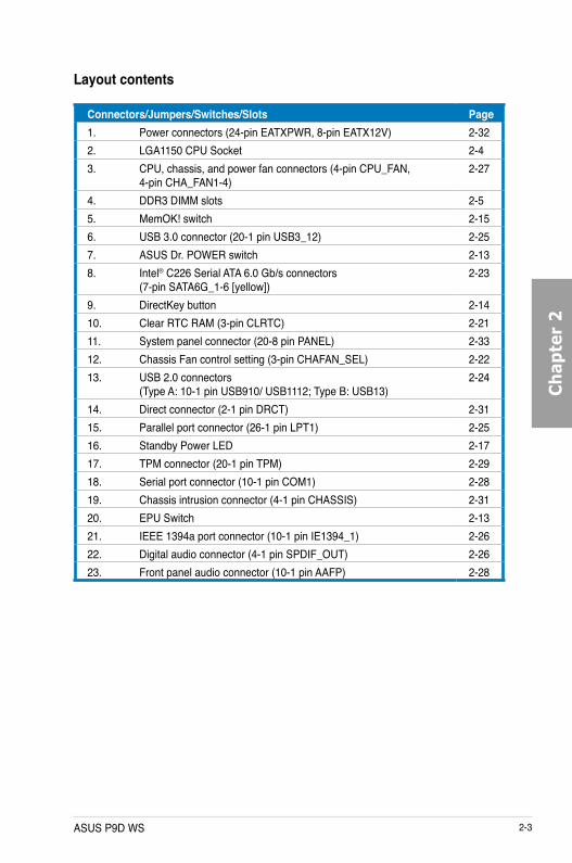
Layout contents
Connectors/Jumpers/Switches/Slots Page1. Power connectors (24-pin EATXPWR, 8-pin EATX12V) 2-322. LGA1150 CPU Socket 2-43. CPU, chassis, and power fan connectors (4-pin CPU_FAN,
4-pin CHA_FAN1-4)2-27
4. DDR3 DIMM slots 2-55. MemOK! switch 2-156. USB 3.0 connector (20-1 pin USB3_12) 2-257. ASUS Dr. POWER switch 2-138. Intel® C226 Serial ATA 6.0 Gb/s connectors
(7-pin SATA6G_1-6 [yellow])2-23
9. DirectKey button 2-1410. Clear RTC RAM (3-pin CLRTC) 2-2111. System panel connector (20-8 pin PANEL) 2-3312. Chassis Fan control setting (3-pin CHAFAN_SEL) 2-2213. USB 2.0 connectors
(Type A: 10-1 pin USB910/ USB1112; Type B: USB13)2-24
14. Direct connector (2-1 pin DRCT) 2-3115. Parallel port connector (26-1 pin LPT1) 2-2516. Standby Power LED 2-1717. TPM connector (20-1 pin TPM) 2-2918. Serial port connector (10-1 pin COM1) 2-2819. Chassis intrusion connector (4-1 pin CHASSIS) 2-3120. EPU Switch 2-1321. IEEE 1394a port connector (10-1 pin IE1394_1) 2-2622. Digital audio connector (4-1 pin SPDIF_OUT) 2-2623. Front panel audio connector (10-1 pin AAFP) 2-28

2-4 Chapter 2: Hardware information
Ch
apter 2
2.2.2 Central Processing Unit (CPU)
The motherboard comes with a surface mount LGA1150 socket designed for the Intel® 4th Generation Core™ i3 desktop Processors and Intel® Xeon® E3-1200/ 12x5 v3 series Server/Workstation Processors.
Ensure that all power cables are unplugged before installing the CPU.
• Ensure that all power cables are unplugged before installing the CPU.
• Ensure that you install the correct CPU designed for LGA1150 only. DO NOT install a CPU designed for LGA1155 and LGA1156 sockets on the LGA1150 socket.
• Upon purchase of the motherboard, ensure that the PnP cap is on the socket and the socket contacts are not bent. Contact your retailer immediately if the PnP cap is missing, or if you see any damage to the PnP cap/socket contacts/motherboard components. ASUS will shoulder the cost of repair only if the damage is shipment/transit-related.
• Keep the cap after installing the motherboard. ASUS will process Return Merchandise Authorization (RMA) requests only if the motherboard comes with the cap on the LGA1150 socket.
• The product warranty does not cover damage to the socket contacts resulting from incorrect CPU installation/removal, or misplacement/loss/incorrect removal of the PnP cap.

ASUS P9D WS 2-5
Ch
apte
r 2
Recommended memory configurations
2.2.3 System memoryThe motherboard comes with four Double Data Rate 3 (DDR3) Dual Inline Memory Modules (DIMM) slots.
A DDR3 module is notched differently from a DDR or DDR2 module. DO NOT install a DDR or DDR2 memory module to the DDR3 slot.

2-6 Chapter 2: Hardware information
Ch
apter 2
Memory configurationsYou may install 1GB, 2GB, 4GB, 8GB unbuffered ECC or non-ECC DDR3 DIMMs into the DIMM sockets depending on the installed CPU.
• You may install varying memory sizes in Channel A and Channel B. The system maps the total size of the lower-sized channel for the dual-channel configuration. Any excess memory from the higher-sized channel is then mapped for single-channel operation.
• According to Intel CPU spec, DIMM voltage below 1.5V is recommended to protect the CPU.
• The max. 32GB memory capacity can be supported with DIMMs of 8GB.
• Always install DIMMs with the same CAS latency. For optimum compatibility, we recommend that you obtain memory modules from the same vendor.
• Due to the memory address limitation on 32-bit Windows OS, when you install 4GB or more memory on the motherboard, the actual usable memory for the OS can be about 3GB or less. For effective use of memory, we recommend that you do any of the following: - Use a maximum of 3GB system memory if you are using a 32-bit Windows OS. - Install a 64-bit Windows OS when you want to install 4GB or more on the
motherboard. For more details, refer to the Microsoft® support site at http://support.microsoft.com/kb/929605/en-us.
• This motherboard does not support DIMMs made up of 512Mb (64MB) chips or less (Memory chip capacity counts in Megabit, 8 Megabit/Mb = 1 Megabyte/MB).
For system stability, use a more efficient memory cooling system to support a full memory load (4 DIMMs) or overclocking condition.
P9D WS Motherboard Qualified Vendors Lists (QVL)
• ASUS exclusively provides hyper DIMM support function.
• Hyper DIMM support is subject to the physical characteristics of individual CPUs. Load the X.M.P. or D.O.C.P. settings in the BIOS for the hyper DIMM support.
• Visit the ASUS website for the latest QVL.

ASUS P9D WS 2-7
Ch
apte
r 2
P9D WS Motherboard Qualified Vendors Lists (QVL) DDR3 1600 MHz capabilityVendors Part No. Size SS/
DSChip Brand
Chip NO. Timing Voltage DIMM socket support (Optional)2 4
A-DATA AD3U1600C2G11 2GB SS MICRON D9PFJ 11-11-11-28 - • •A-DATA AD3U1600C4G11 4GB DS MICRON D9PFJ 11-11-11-28 - • •A-DATA AD3U1600W4G11 4GB SS A-DATA 3WCD-1211A 11-11-11-28 - • •A-DATA AD3U1600W8G11 8GB DS A-DATA 3WCD-1211A 11-11-11-28 - • •A-DATA AX3U1600GW8G9(XMP) 16GB ( 2x 8GB ) DS - - 9-9-9-24 1.5 • •A-DATA AX3U1600W8G11 16GB ( 2x 8GB ) DS - - 9-11-9-27 1.5 • •A-DATA AXDU1600GW8G9B(XMP) 16GB ( 2x 8GB ) DS - - 9-11-9-27 1.65 • •AMD AE32G1609U1-U 2GB SS AMD 23EY4587MB6H - 1.5 • •AMD AE34G1609U2-U 4GB DS AMD 23EY4587MB6H - 1.5 • •AMD AP38G1608U2K(XMP) 8GB ( 2x 4GB ) DS - - 9-9-9-28 1.65 • •Apacer 78.B1GE3.9L10C 4GB DS Apacer AM5D5908DEQSCK - 1.65 • •Apacer 78.B1GET.9K00C 4GB SS Apacer AM5D6008BQQSCK 11-11-11-28 - • •Apacer 78.C1GET.9K10C 8GB DS Apacer AM5D6008BQQSCK 11-11-11-31 - • •Apacer AHU04GFA60C9Q3R(XMP) 4GB DS - - 11-11-11-28 - • •Asint SLA302G08-EGG1C(XMP) 4GB DS Asint 302G08-GG1C 9-9-9-27 - • •Asint SLA302G08-EGJ1C(XMP) 4GB DS Asint 302G08-GJ1C 9-9-9-27 - • •Asint SLA302G08-EGN1C 4GB DS ASint 302G08-GN1C - - • •Asint SLA304G08-ENG1B 4GB SS Asint 304G08-GN1B 9-11-11-28 - • •Asint SLB304G08-EGJ1B(XMP) 8GB DS - - 9-9-9-27 - • •Asint SLB304G08-EGN1B 8GB DS ASint 304G08-GN1B - - • •Asint SLZ302G08-EGN1C 2GB SS ASint 302G08-GN1C - - • •Asint SLZ3128M8-EGJ1D(XMP) 2GB DS Asint 3128M8-GJ1D - - • •CORSAIR CMD16GX3M2A1600C9
(Ver8.21)(XMP)16GB ( 2x 8GB ) DS - - 9-9-9-24 1.5 •
CORSAIR CMD8GX3M2A1600C8 (Ver5.12)(XMP)
8GB ( 2x 4GB ) DS - - 1600 8-8-8-24 1.5 • •
CORSAIR CMD8GX3M2A1600C9 (Ver2.12)(XMP)
8GB ( 2x 4GB ) DS - - 9-9-9-24 1.5 • •
CORSAIR CMG4GX3M2A1600C6 4GB ( 2x 2GB ) DS - - 6-6-6-18 1.65 • •CORSAIR CML16GX3M4X1600C8(Ver
2.12)(XMP)16GB ( 4x 4GB ) DS - - Heat-Sink
Package1.5 •
CORSAIR CMP6GX3M3A1600C8(XMP) 6GB ( 3x 2GB ) DS - - 8-8-8-24 1.65 • •CORSAIR CMP6GX3M3A1600C8(XMP) 6GB ( 3x 2GB ) DS - - 8-8-8-24 1.65 • •CORSAIR CMX6GX3M3C1600C7(XMP) 6GB ( 3x 2GB ) DS - - 7-8-7-20 1.65 • •CORSAIR CMX8GX3M2A1600C9
(Ver3.19)(XMP)8GB ( 2x 4GB ) SS - - 9-9-9-24 1.65 • •
CORSAIR CMZ16GX3M2A1600C10 (Ver.3.24)(XMP)
16GB ( 2x 8GB ) DS - - 10-10-10-27 1.5 • •
CORSAIR CMZ16GX3M4A1600C9 (XMP)
16GB ( 4x 4GB ) DS - - 9-9-9-24 1.5 • •
CORSAIR CMZ32GX3M4X1600C10 (Ver2.2)(XMP)
32GB ( 4x 8GB ) DS - - 10-10-10-27 1.5 • •
CORSAIR CMZ8GX3M2A1600C8(XMP) 8GB ( 2x 4GB ) DS - - 8-8-8-24 1.5 • •CORSAIR CMZ8GX3M4X1600C9 (Ver
2.12)(XMP)8GB ( 4x 2GB ) SS - - 9-9-9-24 1.5 • •
CORSAIR HX3X12G1600C9 (XMP) 12GB ( 6x 2GB ) DS - - 9-9-9-24 1.6 • •Crucial BL12864BN1608.8FF (XMP) 2GB ( 2x 1GB ) SS - - 8-8-8-24 1.65 • •Crucial BLT4G3D1608DT1TX0.16FM
(XMP)4GB DS - - 8-8-8-24 1.5 • •
EK Memory EKM324L28BP8-I16 (XMP) 4GB ( 2x 2GB ) DS - - 9 - • •EK Memory EKM324L28BP8-I16 (XMP) 4GB ( 2x 2GB ) DS - - 9 - • •Elixir M2X2G64CB88G7N-DG
(XMP)2GB SS Elixir N2CB2G80GN-DG 9-9-9-28 - • •
Elixir M2X4G64CB8HG5N-DG (XMP)
4GB DS Elixir N2CB2G80GN-DG 9-9-9-28 - • •
Elixir M2X8G64CB8HB5N-DG (XMP)
8GB DS Elixir N2CB4G80BN-DG 9-9-9-28 1.5 • •

2-8 Chapter 2: Hardware information
Ch
apter 2
P9D WS Motherboard Qualified Vendors Lists (QVL) DDR3 1600 MHz capabilityVendors Part No. Size SS/
DSChip Brand
Chip NO. Timing Voltage DIMM socket support (Optional)2 4
G.SKILL F3-12800CL7D-8GBRH (XMP)
8GB ( 2x 4GB ) DS - - 7-8-7-24 1.6 • •
G.SKILL F3-12800CL7Q-16GBXH (XMP)
16GB ( 4x 4GB ) DS - - 7-8-7-24 1.6 • •
G.SKILL F3-12800CL8D-8GBECO (XMP)
8GB ( 2x4GB ) DS - - 8-8-8-24 1.35 •
G.SKILL F3-12800CL9D-8GBRL(XMP) 8GB ( 2x 4GB ) DS - - 9-9-9-24 1.5 • •G.SKILL F3-12800CL9D-
8GBSR2(XMP)8GB ( 2x 4GB ) DS - - 9-9-9-24 1.25 • •
G.SKILL F3-12800CL9Q-16GBXL(XMP)
16GB ( 4x 4GB ) DS - - 9-9-9-24 1.5 • •
G.Skill F3-12800CL9Q-16GBZL(XMP)
16GB ( 4x 4GB ) DS - - 9-9-9-24 1.5 • •
G.SKILL F3-1600C9Q-32GXM(XMP) 32GB ( 4x 8GB ) DS - - - 1.5 • •GEIL GET316GB1600C9QC(XMP) 16GB ( 4x 4GB ) DS - - 9-9-9-28 1.6 • •GEIL GUP34GB1600C7DC(XMP) 4GB ( 2x 2GB ) DS - - 7-7-7-24 1.6 • •GoodRam GR1600D364L9/2G 2GB DS GoodRam GF1008KC-JN - - • •KINGMAX FLGE85F-C8KL9A(XMP) 2GB SS KINGMAX N/A 9-9-9-28 - • •KINGMAX FLGF65F-C8KL9A(XMP) 4GB DS KINGMAX N/A 9-9-9-28 - • •KINGSTON KHX16009CD3K2/8GX(XMP) 8GB ( 2x 4GB ) DS - - 9-9-9-27 1.65 • •KINGSTON KHX1600C9D3B1/4G(XMP) 4GB SS - - 9-9-9-27 1.65 • •KINGSTON KHX1600C9D3K3/
12GX(XMP)12GB ( 3x 4GB ) DS - - 9 1.65 •
KINGSTON KHX1600C9D3K3/6GX(XMP) 6GB ( 3x 2GB ) DS - - 9 1.65 • •KINGSTON KHX1600C9D3K3/6GX(XMP) 6GB ( 3x 2GB ) DS - - 9 1.65 • •KINGSTON KHX1600C9D3K4/
16GX(XMP)16GB ( 4x 4GB ) DS - - 9-9-9-24 1.65 • •
KINGSTON KHX1600C9D3K6/24GX(XMP)
24GB ( 6x 4GB ) DS - - 9 1.65 • •
KINGSTON KHX1600C9D3K8/32GX(XMP)
32GB ( 8x 4GB ) DS - - 9-9-9-27 1.65 • •
KINGSTON KHX1600C9D3LK2/8GX(XMP)
8GB ( 2x 4GB ) DS - - 9-9-9-24 1.35 • •
KINGSTON KHX1600C9D3P1K2/8G 8GB ( 2x 4GB ) DS - - 9 1.5 • •KINGSTON KHX16C10B1K2/16X(XMP) 16GB ( 2x 8GB ) DS - - - 1.5 • •KINGSTON KHX16C9P1K2/16 16GB ( 2x 8GB ) DS - - - 1.5 • •KINGSTON KVR16N11/4 4G DS Hynix H5TQ2G83CFRPBC - 1.5 • •KINGTIGER KTG2G1600PG3(XMP) 2GB DS - - - - • •MICRON MT16JTF1G64AZ-1G6D1 8GB DS MICRON D9PBC - 1.5 • •Micron MT16JTF1G64AZ-1G6E1 8GB DS Micron D9QBJ - - • •MICRON MT16KTF51264AZ-1G6M1 4GB DS MICRON D9PFJ - - • •Micron MT8JTF51264AZ-1G6E1 4GB SS Micron D9QBJ - - • •MICRON MT8KTF25664AZ-1G6M1 2GB SS MICRON D9PFJ - - • •Mushkin 996805(XMP) 4GB ( 2x 2GB ) DS - - 6-8-6-24 1.65 •Mushkin 998805(XMP) 6GB ( 3x 2GB ) DS - - 6-8-6-24 1.65 •OCZ OCZ3BE1600C8LV4GK 4GB ( 2x 2GB ) DS - - 8-8-8 1.65 •Patriot PGD316G1600ELK(XMP) 16GB ( 2x 8GB ) DS - - - 1.65 • •Patriot PGD316G1600ELK(XMP) 16GB ( 2x 8GB ) DS - - 9-9-9-24 1.5 •Patriot PGD38G1600ELK(XMP) 8GB ( 2x 4GB ) DS - - 9-9-9-24 1.65 • •Patriot PGD38G1600ELK(XMP) 8GB ( 2x 4GB ) DS - - 9-9-9-24 1.5 •Patriot PGS34G1600LLKA2 4GB ( 2x 2GB ) DS - - 8-8-8-24 1.7 • •Patriot PV38G160C9KRD(XMP) 8GB ( 2x 4GB ) DS - - 9-9-9-24 1.5 • •Patriot PVV38G1600LLK(XMP) 8GB ( 2x 4GB ) DS - - 8-9-8-24 1.65 • •Patriot PX7312G1600LLK(XMP) 12GB ( 3x 4GB ) DS - - 8-9-8-24 1.65 • •Patriot PXD38G1600LLK(XMP) 8GB ( 2x 4GB ) DS - - 1600 8-9-8-24 1.65 • •PSC AL9F8L93B-GN2E 4GB SS PSC A3P4GF3BLF - - • •PSC ALAF8L93B-GN2E 8GB DS PSC A3P4GF3BLF - - • •SanMax SMD-4G68HP-16KZ 4GB DS Hynix H5TQ2G83BFRPBC - 1.5 • •

ASUS P9D WS 2-9
Ch
apte
r 2
Vendors Part No. Size SS/DS
Chip Brand Chip NO. Timing Voltage DIMM socket support (Optional)2 4
ACTICA ACT1GHU64B8F1333S 1GB SS SAMSUNG K4B1G0846F - - • •ACTICA ACT1GHU72C8G1333S 1GB SS SAMSUNG K4B1G0846F(ECC) - - • •ACTICA ACT2GHU64B8G1333M 2GB DS Micron D9KPT - - • •ACTICA ACT2GHU72D8G1333M 2GB DS Micron D9KPT(ECC) - - • •ACTICA ACT2GHU72D8G1333S 2GB DS SAMSUNG K4B1G0846F(ECC) - - • •ACTICA ACT4GHU64B8H1333H 4GB DS Hynix H5TQ2G83AFR - - • •ACTICA ACT4GHU72D8H1333H 4GB DS Hynix H5TQ2G83AFR(ECC) - - • •AMD AE32G1339U1-U 2GB SS AMD 23EY4587MB3H - 1.5 • •AMD AE34G1339U2-U 4GB DS AMD 23EY4587MB3H - 1.5 • •Apacer 78.A1GC6.9L1 2GB DS Apacer AM5D5808FEQSBG 9 - • •Apacer 78.B1GDE.9L10C 4GB DS Apacer AM5D5908CEHSBG 9 - • •Asint SLA302G08-EDJ1C 2GB SS ASint 302G08-DJ1C - - • •Asint SLA304G08-EDJ1B 4GB SS Asint 304G08-DJ1B 9-10-10-26 - • •Asint SLB304G08-EDJ1B 8GB DS Asint 304G08-DJ1B 9-9-9-24 - • •Asint SLZ302G08-EDJ1C 4GB DS ASint 302G08-DJ1C - - • •ATP AQ12M72E8BKH9S 4GB DS SAMSUNG K4B2G0846C(ECC) - - • •BUFFALO D3U1333-1G 1GB SS Elpida J1108BFBG-DJ-F - - • •BUFFALO D3U1333-2G 2GB DS Elpida J1108BFBG-DJ-F - • •BUFFALO D3U1333-4G 4GB DS NANYA NT5CB256M8BN-CG - • •CORSAIR CMV4GX3M2A1333C9 4GB ( 2x 2GB ) SS - N/A 9-9-9-24 - • •CORSAIR CMV8GX3M2A1333C9 8GB ( 2x 4GB ) DS - N/A 9-9-9-24 - • •CORSAIR CMX8GX3M1A1333C9
(Ver2.2)8GB DS - - 9-9-9-24 1.5 •
CORSAIR CMX8GX3M1A1333C9 (Ver3.23)
8GB DS - - 9-9-9-24 1.5 •
CORSAIR CMX8GX3M2A1333C9 (XMP)
8GB ( 2x 4GB ) DS - - 9-9-9-24 1.5 • •
CORSAIR TW3X4G1333C9A 4GB ( 2x 2GB ) DS - - 9-9-9-24 1.5 •EK Memory EKM324L28BP8-I13 4GB ( 2x 2GB ) DS - - 9 - • •G.SKILL F3-10600CL9D-4GBNT 4GB ( 2x 2GB ) DS G.SKILL D3 128M8CE9 2GB 9-9-9-24 1.5 •G.SKILL F3-10666CL9D-8GBRL 8GB ( 2x 4GB ) DS - - 9-9-9-24 1.5 • •G.SKILL F3-10666CL9D-8GBRL 8GB ( 2x 4GB ) DS - - 9-9-9-24 1.5 • •
P9D WS Motherboard Qualified Vendors Lists (QVL) DDR3 1600 MHz capabilityVendors Part No. Size SS/
DSChip Brand Chip NO. Timing Voltage DIMM
socket support (Optional)2 4
SanMax SMD-4G68NG-16KK 4GB DS ELPIDA J2108BDBG-GN-F - - • •Silicon Power
SP002GBLTU160V02(XMP) 2GB SS S-POWER 20YT5NG 9-11-11-28 1.5 • •
Silicon Power
SP004GBLTU160V02(XMP) 4GB DS S-POWER 20YT5NG 9-9-9-24 1.5 • •
Team TXD34096M1600HC9-D(XMP)
4GB DS Hynix H5TC2G83BFRH9A 9-9-9-24 1.5 • •
Transcend JM1600KLH-8G(626633) 8GB DS Transcend TK963EBF3 - - • •Transcend TS1GLK64V6H(620945) 8GB DS SAMSUNG K4B4G0846B - - • •Transcend TS1GLK64W6H 8GB DS SAMSUNG K4B4G0846B 11-11-11-28-1 - • •Transcend TS512MLK64W6H 4GB SS SAMSUNG K4B4G0846B 11-11-11-28-2 - • •
P9D WS Motherboard Qualified Vendors Lists (QVL) DDR3 1333 MHz capability

2-10 Chapter 2: Hardware information
Ch
apter 2
Vendors Part No. Size SS/DS
Chip Brand Chip NO. Timing Voltage DIMM socket support (Optional)2 4
G.SKILL F3-10666CL9D-8GBXL 8GB ( 2x 4GB ) DS - - 9-9-9-24 1.5 • •GEIL GET316GB1333C9QC 16GB ( 4x 4GB ) DS - - 9-9-9-24 1.5 • •GEIL GG34GB1333C9DC 4GB ( 2x 2GB ) DS GEIL GL1L128M88BA115FW 9-9-9-24 1.3 • •GEIL GG34GB1333C9DC 4GB ( 2x 2GB ) DS GEIL GL1L128M88BA15B 9-9-9-24 1.3 • •GEIL GVP34GB1333C9DC 4GB ( 2x 2GB ) DS - - 9-9-9-24 1.5 • •GEIL GVP38GB1333C9DC 8GB ( 2x 4GB ) DS - - 9-9-9-24 1.5 • •GoodRam GR1333D364L9/2G 2GB DS Qimonda IDSH1G-03A1F1C-13H - - • •Hynix HMT125U6TFR8A-H9 2GB DS Hynix H5TC1G83TFR - - • •INNODISK M3UN-2GHJBC09 2GB SS Hynix H5TQ2G83CFRH9C 9-9-9-24 - • •INNODISK M3UN-4GHJAC09 4GB DS Hynix H5TQ2G83CFRH9C 9-9-9-24 - • •KINGMAX FLFE85F-B8KL9 2GB DS KINGMAX KFB8FNLXL-BNF-15A - - • •KINGMAX FLFE85F-C8KL9 2GB SS KINGMAX KFC8FNLBF-GXX-12A - - • •KINGMAX FLFE85F-C8KL9 2GB SS KINGMAX KFC8FNLXF-DXX-15A - - • •KINGMAX FLFE85F-C8KM9 2GB SS Kingmax KFC8FNMXF-BXX-15A - - • •KINGMAX FLFF65F-C8KL9 4GB DS KINGMAX KFC8FNLXF-DXX-15A - - • •KINGMAX FLFF65F-C8KM9 4GB DS Kingmax KFC8FNMXF-BXX-15A - - • •KINGSTON KVR1333D3E9S/4G 4GB DS Elpida J2108ECSE-DJ-F 9 1.5 • •KINGSTON KVR1333D3N9H/4G 4GB DS ELPIDA J2108BDBG-GN-F - 1.5 • •KINGSTON KVR1333D3N9H/8G 8GB DS ELPIDA J4208EASE-DJ-F 9-9-9-24 1.5 • •KINGSTON KVR13N9S8H/4 4GB SS ELPIDA J4208BBBG-GN-F - 1.5 • •KINGTIGER F10DA2T1680 2GB DS KINGTIGER KTG1333PS1208NST-C9 - - • •KINGTIGER KTG2G1333PG3 2GB DS - - - - • •Mach Xtreme MXD3U133316GQ 16GB ( 4x 4GB ) DS - - - - • •Mach Xtreme MXD3V13332GS 2GB SS Mach
XtremeC2S46D30-D313 - - • •
MICRON MT8JTF25664AZ-1G4M1 2GB SS MICRON D9PFJ - - • •OCZ OCZ3G1333LV4GK 4GB ( 2x 2GB ) DS - - 9-9-9 1.65 •OCZ OCZ3G1333LV8GK 8GB ( 2x 4GB ) DS - - 9-9-9 1.65 •OCZ OCZ3G1333LV8GK 8GB ( 2x 4GB ) DS - - 9-9-9 1.65 •OCZ OCZ3RPR1333C9LV8GK 8GB ( 2x 4GB ) DS - - 9-9-9 1.65 •Patriot PG38G1333EL (XMP) 8GB DS - - - 1.5 • •Patriot PGD316G1333ELK (XMP) 16GB ( 2x 8GB ) DS - - 9-9-9-24 1.5 • •Patriot PSD32G13332 2GB DS Prtriot PM128M8D3BU-15 9 - • •RiDATA C304627CB1AG22Fe 2GB DS RiDATA C304627CB1AG22Fe 9 - • •RiDATA E304459CB1AG32Cf 4GB DS RiDATA E304459CB1AG32Cf 9 - • •SAMSUNG M378B5273CH0-CH9 4GB DS SAMSUNG K4B2G0846C - - • •Silicon Power
SP001GBLTE133S01 1GB SS NANYA NT5CB128M8AN-CG - - • •
Silicon Power
SP001GBLTU133S02 1GB SS S-POWER 10YT3E5 9 - • •
Silicon Power
SP002GBLTU133V02 2GB SS S-POWER 20YT3NG 9-9-9-24 - • •
Silicon Power
SP004GBLTU133V02 4GB DS S-POWER 20YT3NG 9-9-9-24 - • •
Team TED34096M1333HC9 4GB DS Team T3D2568LT-13 - - • •Transcend JM1333KLH-8G(623654) 8GB DS Transcend TK963EBF3 - - • •Transcend TS1GLK64V3H(620053) 8GB DS MICRON D9QBJ - - • •
P9D WS Motherboard Qualified Vendors Lists (QVL) DDR3 1333 MHz capability
ASUS P9D WS 2-11
Ch
apte
r 2
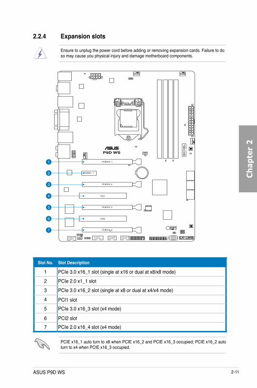
2.2.4 Expansion slots
Ensure to unplug the power cord before adding or removing expansion cards. Failure to do so may cause you physical injury and damage motherboard components.
Slot No. Slot Description
1 PCIe 3.0 x16_1 slot (single at x16 or dual at x8/x8 mode)2 PCIe 2.0 x1_1 slot3 PCIe 3.0 x16_2 slot (single at x8 or dual at x4/x4 mode)4 PCI1 slot5 PCIe 3.0 x16_3 slot (x4 mode)
6 PCI2 slot7 PCIe 2.0 x16_4 slot (x4 mode)
PCIE x16_1 auto turn to x8 when PCIE x16_2 and PCIE x16_3 occupied; PCIE x16_2 auto turn to x4 when PCIE x16_3 occupied.
2-12 Chapter 2: Hardware information
Ch
apter 2
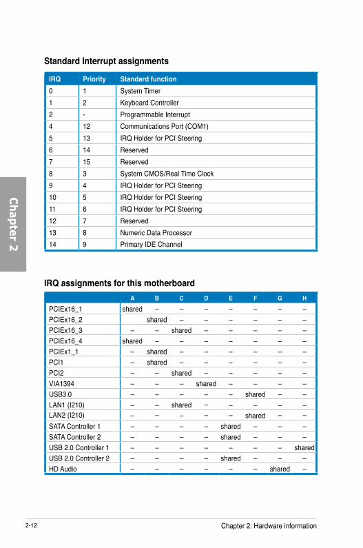
IRQ assignments for this motherboardA B C D E F G H
PCIEx16_1 shared – – – – – – –PCIEx16_2 shared – – – – – –PCIEx16_3 – – shared – – – – –PCIEx16_4 shared – – – – – – –PCIEx1_1 – shared – – – – – –PCI1 – shared – – – – – –PCI2 – – shared – – – – –VIA1394 – – – shared – – – –USB3.0 – – – – – shared – –LAN1 (I210) – – shared – – – – –LAN2 (I210) – – – – – shared – –SATA Controller 1 – – – – shared – – –SATA Controller 2 – – – – shared – – –USB 2.0 Controller 1 – – – – – – – sharedUSB 2.0 Controller 2 – – – – shared – – –HD Audio – – – – – – shared –
IRQ Priority Standard function0 1 System Timer1 2 Keyboard Controller2 - Programmable Interrupt4 12 Communications Port (COM1)5 13 IRQ Holder for PCI Steering6 14 Reserved7 15 Reserved8 3 System CMOS/Real Time Clock9 4 IRQ Holder for PCI Steering10 5 IRQ Holder for PCI Steering11 6 IRQ Holder for PCI Steering12 7 Reserved13 8 Numeric Data Processor14 9 Primary IDE Channel
Standard Interrupt assignments

ASUS P9D WS 2-13
Ch
apte
r 2
2.2.5 Onboard buttons and switchesOnboard buttons and switches enhance overclocking and gaming performance when working on a bare or open-case system.
1. EPU switchTurning this switch to Enable will automatically detect the current PC loadings and intelligently moderate the power consumption.
For ensuring the system performance, turn the switch setting to Enable when the system is powered off.
2. ASUS Dr. POWER switch
This switch allows you to enable or disable the ASUS Dr. Power feature. Install the bundled ASUS Dr. Power Utility then enable this switch to allow the system to display notification messages in your Windows screen if a problem is detected with your power supply unit (PSU).

2-14 Chapter 2: Hardware information
Ch
apter 2
Ensure to save your data before using the DirectKey button.
3. DirectKey button
This feature allows your system to go to the BIOS Setup program with the press of a button. With DirectKey, you can enter the BIOS anytime without having to press the <Del> key during POST. It also allows you to turn on or turn off your system and conveniently enter the BIOS during boot-up.
• When the system is on and you press the DirectKey button, your system will shut down. Press the DirectKey button again or the Power-on button to reboot and enter the BIOS directly.
• Turn off your system using the power-on button to allow your system to go through POST (without entering the BIOS) when you reboot your system.
• Refer to section 3.8 Boot Menu for details about setting the DirectKey default function.

ASUS P9D WS 2-15
Ch
apte
r 2
4. MemOK! buttonWhen you install DIMMs that are not compatible with the motherboard, this may cause the system boot failure, and the DIAG_DRAM near the MemOK switch lights continuously. Simply press the MemOK button until the DIAG_DRAM starts blinking to patch memory compatibility issues and ensure the system’s successful bootup.
• Refer to section 2.2.6 Onboard LEDs for the exact location of the DIAG_DRAM.
• The DIAG_DRAM also lights when the DIMM is not properly installed. Turn off the system and reinstall the DIMM before using the MemOK! function.
• The MemOK! button does not function under Windows™ OS environment.
• During the tuning process, the system loads and tests failsafe memory settings. It takes about 30 seconds for the system to test one set of failsafe settings. If the test fails, the system reboots and test the next set of failsafe settings. The blinking speed of the DIAG_DRAM increases, indicating different test processes.
• Due to memory tuning requirement, the system automatically reboots when each timing set is tested. If the installed DIMMs still fail to boot after the whole tuning process, the DIAG_DRAM lights continuously. Replace the DIMMs with ones recommended in the Memory QVL (Qualified Vendors Lists) in this user manual or on the ASUS website at www.asus.com.
• If you turn off the computer and replace DIMMs during the tuning process, the system continues memory tuning after turning on the computer. To stop memory tuning, turn off the computer and unplug the power cord for about 5–10 seconds.
• If your system fails to boot up due to BIOS overclocking, press the MemOK! button to boot and load the BIOS default settings. A message will appear during POST reminding you that the BIOS has been restored to its default settings.
• We recommend that you download and update to the latest BIOS version from the ASUS website at www.asus.com after using the MemOK! function.

2-16 Chapter 2: Hardware information
Ch
apter 2
2.2.6 Onboard LEDs1. POST State LEDs
The POST State LEDs indicate the status of these key components during POST (Power-on-Self Test): CPU, memory modules, VGA card, and hard disk drive. If an error is found, the critical component’s LED stays lit up until the problem is solved.
2. EPU LEDThe EPU LED lights up when the EPU switch is turned to Enable.

ASUS P9D WS 2-17
Ch
apte
r 2
3. Standby power LEDThe motherboard comes with a standby power LED that lights up to indicate that the system is ON, in sleep mode, or in soft-off mode. This is a reminder that you should shut down the system and unplug the power cable before removing or plugging in any motherboard component. The illustration below shows the location of the onboard LED.
4. DIAG_DRAMThe DIAG_DRAM lights up when the installed DIMMs incompatible with the motherboard or improperly installed. When using the MemOK! switch for automatic memory compatibility tuning, the DIAG_DRAM will blink.

2-18 Chapter 2: Hardware information
Ch
apter 2
5. PWR_SUPPLY LEDThe ASUS Dr. Power LED near EATX PWR connector lights up when the ASUS Dr. Power switch setting is turned to Enable and the power supply unit failed.
6. PGLED3 LEDThe ASUS Dr. Power LED near the ASUS Dr. Power switch lights up when the ASUS Dr. Power switch is turned to enable.

ASUS P9D WS 2-19
Ch
apte
r 2
7. +12V_PWR LEDThe ASUS Dr. Power LED near EATX12V connector lights up when the ASUS Dr. Power switch setting is turned to enable and there is no power detected going into the processor.
8. CPU warning LED (CPU_PWR_ERR)The CPU warning LEDs light up to indicate an impending failure of the corresponding CPU.

2-20 Chapter 2: Hardware information
Ch
apter 2
9. DIMM warning LED (DRAM_PWR_ERR)The DIMM warning LEDs light up to indicate an impending failure of the corresponding DIMMs.

ASUS P9D WS 2-21
Ch
apte
r 2
2.2.7 Jumper1. Clear RTC RAM (3-pin CLRTC)
This jumper allows you to clear the Real Time Clock (RTC) RAM in CMOS. You can clear the CMOS memory of date, time, and system setup parameters by erasing the CMOS RTC RAM data. The onboard button cell battery powers the RAM data in CMOS, which include system setup information such as system passwords.
To erase the RTC RAM
1. Turn OFF the computer and unplug the power cord.2. Move the jumper cap from pins 1-2 (default) to pins 2-3. Keep the cap on pins 2-3
for about 5–10 seconds, then move the cap back to pins 1-2.3. Plug the power cord and turn ON the computer.4. Hold down the <Del> key during the boot process and enter BIOS setup to re-
enter data.
Except when clearing the RTC RAM, never remove the cap on CLRTC jumper default position. Removing the cap will cause system boot failure!
• If the steps above do not help, remove the onboard battery and move the jumper again to clear the CMOS RTC RAM data. After the CMOS clearance, reinstall the battery.
• You do not need to clear the RTC when the system hangs due to overclocking. For system failure due to overclocking, use the C.P.R. (CPU Parameter Recall) feature. Shut down and reboot the system so the BIOS can automatically reset parameter settings to default values.
• Due to the chipset behavior, AC power off is required to enable C.P.R. function. You must turn off and on the power supply or unplug and plug the power cord before rebooting the system.

2-22 Chapter 2: Hardware information
Ch
apter 2
2. Chassis Fan control setting (3-pin CHAFAN_SEL)These jumpers allow you to switch for fan pin selection. The CHAFAN_SEL jumper is for the front fans and rear fans control. Set to pins 1–2 when using 3-pin fans or pins 2–3 when using 4-pin fans.
• If you use a 4-pin fan but set the jumper to pin 1-2, the fan you installed may not work.
• If you use a 3-pin fan but set the jumper for a 4-pin fan, the fan control will not work and the fan you installed will always run at full speed.

ASUS P9D WS 2-23
Ch
apte
r 2
2.2.8 Internal connectors
1. Intel® C226 Serial ATA 6.0 Gb/s connectors (7-pin SATA6G_1-6 [yellow])These connectors connect to Serial ATA 6.0 Gb/s hard disk drives via Serial ATA 6.0 Gb/s signal cables.
• These connectors are set to [AHCI Mode] by default. If you intend to create a Serial ATA RAID set using these connectors, set the SATA Mode item in the BIOS to [RAID Mode]. Refer to section 3.5.4 SATA Configuration for details.
• Before creating a RAID set, refer to section 4.5 RAID configurations or the manual bundled in the motherboard support DVD.
• When using NCQ, set the SATA Mode in the BIOS to [AHCI Mode]. Refer to section 3.5.4 SATA Configuration for details.
• You must install Windows® XP Service Pack 3 or later versions before using Serial ATA hard disk drives. The Serial ATA RAID feature is available only if you are using Windows® XP SP3 or later versions.
2-24 Chapter 2: Hardware information
Ch
apter 2
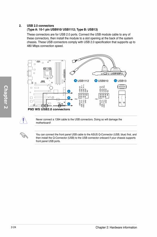
You can connect the front panel USB cable to the ASUS Q-Connector (USB, blue) first, and then install the Q-Connector (USB) to the USB connector onboard if your chassis supports front panel USB ports.
Never connect a 1394 cable to the USB connectors. Doing so will damage the motherboard!
2. USB 2.0 connectors (Type A: 10-1 pin USB910/ USB1112; Type B: USB13)These connectors are for USB 2.0 ports. Connect the USB module cable to any of these connectors, then install the module to a slot opening at the back of the system chassis. These USB connectors comply with USB 2.0 specification that supports up to 480 Mbps connection speed.

ASUS P9D WS 2-25
Ch
apte
r 2
3. USB 3.0 connector (20-1 pin USB3_12)These connectors allow you to connect a USB 3.0 module for additional USB 3.0 front or rear panel ports. With an installed USB 3.0 module, you can enjoy all the benefits of USB 3.0 including faster data transfer speeds of up to 5Gbps, faster charging time for USB-chargeable devices, optimized power efficiency and backward compatibility with USB 2.0.
4. Parallel port connector (26-1 pin LPT1)This connector is for a parallel port. Connect the parallel port module cable to this connector, then install the module to a slot opening at the back of the system chassis.
The USB 3.0 module is purchased separately.

2-26 Chapter 2: Hardware information
Ch
apter 2
5. IEEE 1394a port connector (10-1 pin IE1394_1)This connector is for an IEEE 1394a port. Connect the IEEE 1394a module cable to this connector, then install the module to a slot opening at the back of the system chassis.
Never connect a USB cable to the IEEE 1394a connector. Doing so will damage the motherboard!
The IEEE 1394a module is purchased separately.
6. Digital audio connector (4-1 pin SPDIF_OUT)This connector is for an additional Sony/Philips Digital Interface (S/PDIF) port. Connect the S/PDIF Out module cable to this connector, then install the module to a slot opening at the back of the system chassis.
The S/PDIF module is purchased separately.

ASUS P9D WS 2-27
Ch
apte
r 2
7. CPU, chassis, and power fan connectors (4-pin CPU_FAN, 4-pin CHA_FAN1-4)Connect the fan cables to the fan connectors on the motherboard, ensuring that the black wire of each cable matches the ground pin of the connector.
• The CPU_FAN connector supports the CPU fan of maximum 2A (24 W) fan power.
• If you install two VGA cards, we recommend that you plug the rear chassis fan cable to the motherboard connector labeled CHA_FAN1, CHA_FAN2, CHA_FAN3 for better thermal environment.
Do not forget to connect the fan cables to the fan connectors. Insufficient air flow inside the system may damage the motherboard components. These are not jumpers! Do not place jumper caps on the fan connectors!

2-28 Chapter 2: Hardware information
Ch
apter 2
8. Front panel audio connector (10-1 pin AAFP)This connector is for a chassis-mounted front panel audio I/O module that supports either HD Audio or legacy AC`97 audio standard. Connect one end of the front panel audio I/O module cable to this connector.
• We recommend that you connect a high-definition front panel audio module to this connector to avail of the motherboard’s high-definition audio capability.
• If you want to connect a high-definition front panel audio module to this connector, set the Front Panel Type item in the BIOS setup to [HD]; if you want to connect an AC'97 front panel audio module to this connector, set the item to [AC97]. By default, this connector is set to [HD].
9. Serial port connector (10-1 pin COM1)This connector is for a serial (COM) port. Connect the serial port module cable to this connector, then install the module to a slot opening at the back of the system chassis.
The COM module is purchased separately.
ASUS P9D WS 2-29
Ch
apte
r 2
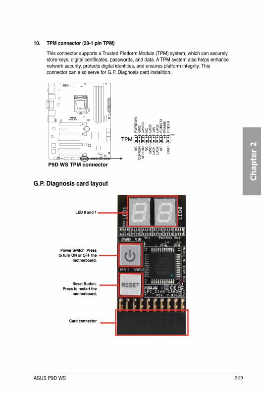
10. TPM connector (20-1 pin TPM)
This connector supports a Trusted Platform Module (TPM) system, which can securely store keys, digital certificates, passwords, and data. A TPM system also helps enhance network security, protects digital identities, and ensures platform integrity. This connector can also serve for G.P. Diagnosis card installtion.
G.P. Diagnosis card layout
LED 0 and 1
Card connector
Power Switch. Press to turn ON or OFF the
motherboard.
Reset Button. Press to restart the
motherboard..

2-30 Chapter 2: Hardware information
Ch
apter 2
Code table for G.P. Diagnosis card15, 19 Initiate chip AC OS in PIC modeE0 Check and wake up system AA OS in APIC mode2B-2F Prepare system for memory
detection and sizingA0 Leave BIOS and pass control
to OS
32 Early CPU initiation 01 S134 Wake up AP 03 S398 Detect PS2 mouse/keyboard 04 S497 Initiate VGA BIOS 05 S59A-9D USB initiation 10 Resume from S1A2 Detect SATA 30 Resume from S3B2 Initiate option ROM 40 Resume from S4
1. Locate the TPM connector (20-1 pin TPM) on the motherboard.2. With the LEDs of the diagnosis card
facing to the PCIe slots, align the card connector with the TPM connector and press firmly until the card sits on the connector completely.
Ensure to turn off the power supply unit before installing the diagnosis card to avoid electrical shock hazard.
Installing G.P. Diagnosis card

ASUS P9D WS 2-31
Ch
apte
r 2
11. Direct Connector (2-pin DRCT)This connector is for the chassis-mounted button that supports the DirectKey function. Connect the button cable that supports DirectKey, from the chassis to this connector on the motherboard.
Ensure that your chassis comes with the extra button cable that supports the DirectKey feature. Refer to the technical documentation that came with the chassis for details.
12. Chassis intrusion connector (4-1 pin CHASSIS)This connector is for a chassis-mounted intrusion detection sensor or switch. Connect one end of the chassis intrusion sensor or switch cable to this connector. The chassis intrusion sensor or switch sends a high-level signal to this connector when a chassis component is removed or replaced. The signal is then generated as a chassis intrusion event.
By default , the pin labeled “Chassis Signal” and “Ground” are shorted with a jumper cap. Remove the jumper caps only when you intend to use the chassis intrusion detection feature.

2-32 Chapter 2: Hardware information
Ch
apter 2
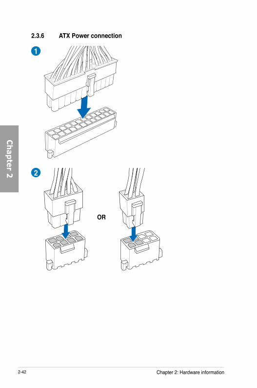
13. ATX power connectors (24-pin EATXPWR, 8-pin EATX12V)These connectors are for ATX power supply plugs. The power supply plugs are designed to fit these connectors in only one orientation. Find the proper orientation and push down firmly until the connectors completely fit.
• For a fully configured system, we recommend that you use a power supply unit (PSU) that complies with ATX 12 V Specification 2.0 (or later version) and provides a minimum power of 350 W.
• Do not forget to connect the 8-pin EATX12 V power plug; otherwise, the system will not boot.
• Use of a PSU with a higher power output is recommended when configuring a system with more power-consuming devices. The system may become unstable or may not boot up if the power is inadequate.
• If you are uncertain about the minimum power supply requirement for your system, refer to the Recommended Power Supply Wattage Calculator at http://support.asus.com/PowerSupplyCalculator/PSCalculator.aspx?SLanguage=en-us for details.
• If you want to use two or more high-end PCI Express x16 cards, use a PSU with 1000W power or above to ensure the system stability.

ASUS P9D WS 2-33
Ch
apte
r 2
• System power LED (2-pin PWR_LED)This 2-pin connector is for the system power LED. Connect the chassis power LED cable to this connector. The system power LED lights up when you turn on the system power, and blinks when the system is in sleep mode.
• Hard disk drive activity LED (2-pin HDD_LED)This 2-pin connector is for the HDD Activity LED. Connect the HDD Activity LED cable to this connector. The HDD LED lights up or flashes when data is read from or written to the HDD.
• System warning speaker (4-pin SPEAKER)This 4-pin connector is for the chassis-mounted system warning speaker. The speaker allows you to hear system beeps and warnings.
• ATX power button/soft-off button (2-pin PWRSW)This connector is for the system power button. Pressing the power button turns the system on or puts the system in sleep or soft-off mode depending on the BIOS settings. Pressing the power switch for more than four seconds while the system is ON turns the system OFF.
• Reset button (2-pin RESET)This 2-pin connector is for the chassis-mounted reset button for system reboot without turning off the system power.
14. System panel connector (20-8 pin PANEL)
This connector supports several chassis-mounted functions.

2-34 Chapter 2: Hardware information
Ch
apter 2
2.3 Building your computer system
2.3.1 Additional tools and components to build a PC system
1 bag of screws Philips (cross) screwdriver
PC chassis Power supply unit
Intel LGA 1150 CPU Intel LGA 1150 compatible CPU Fan
DIMM SATA hard disk drive
SATA optical disc drive (optional) Graphics card (optional)
The tools and components in the table above are not included in the motherboard package.

ASUS P9D WS 2-35
Ch
apte
r 2
A
B
1
2
3
2.3.2 CPU installation

2-36 Chapter 2: Hardware information
Ch
apter 2
C
B
A
5
6
4

ASUS P9D WS 2-37
Ch
apte
r 2
2.3.3 CPU heatsink and fan assembly installation
Apply the Thermal Interface Material to the CPU heatsink and CPU before you install the heatsink and fan if necessary.
To install the CPU heatsink and fan assembly
2B
B
A
A1
3 4

2-38 Chapter 2: Hardware information
Ch
apter 2
To uninstall the CPU heatsink and fan assembly
2A
BB
A
1

ASUS P9D WS 2-39
Ch
apte
r 2
1
2
3
To remove a DIMM
2.3.4 DIMM installation
B
A

2-40 Chapter 2: Hardware information
Ch
apter 2
2.3.5 Motherboard installation
2
1
The diagrams in this section are for reference only. The motherboard layout may vary with models, but the installation steps remain the same.

ASUS P9D WS 2-41
Ch
apte
r 2
DO NOT overtighten the screws! Doing so can damage the motherboard.
3
2-42 Chapter 2: Hardware information
Ch
apter 2
2.3.6 ATX Power connection
1
OR
2

ASUS P9D WS 2-43
Ch
apte
r 2
2.3.7 SATA device connection
OR
2
OR
1
2-44 Chapter 2: Hardware information
Ch
apter 2
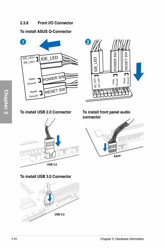
2.3.8 Front I/O Connector
IDE_LED
POWER SW
RESET SW
IDE_LED-IDE_LED+
PWR
Reset
Ground
Ground
2
USB 2.0
1
USB 3.0
To install USB 3.0 Connector
AAFP
To install ASUS Q-Connector
To install USB 2.0 Connector To install front panel audio connector

ASUS P9D WS 2-45
Ch
apte
r 2
2.3.9 Expansion Card installation
To install PCIe x16 cards
To install PCIe x1 cards To install PCI cards

2-46 Chapter 2: Hardware information
Ch
apter 2
• Do not unplug portable disk, power system, or press the CLR_CMOS button while BIOS update is ongoing, otherwise update will be interrupted. In case of interruption, please follow the steps again.
• If the light flashes for five seconds and turns into a solid light, this means that the BIOS Flashback is not operating properly. This may be caused by improper installation of the USB storage device and filename/file format error. If this scenario happens, please restart the system to turn off the light.
• Updating BIOS may have risks. If the BIOS program is damaged during the process and results to the system’s failure to boot up, please contact your local ASUS Service Center.
2.3.10 BIOS update utility
USB BIOS FlashbackUSB BIOS Flashback allows you to easily update the BIOS without entering the existing BIOS or operating system. Simply insert a USB storage device to the USB port, press the USB BIOS Flashback button for three seconds, and the BIOS is updated automatically.
To use USB BIOS Flashback:
1. Place the bundled support DVD to the optical drive and install the USB BIOS Flashback Wizard. Follow the onscreen instructions to complete the installation.
2. Insert the USB storage device to the USB Flashback port.
We recommend you to use a USB 2.0 storage device to save the latest BIOS version for better compatibility and stability.
3. Launch the USB BIOS Flashback Wizard to automatically download the latest BIOS version.
4. Press the BIOS Flashback button for three seconds until a flashing light appears, which indicates that the BIOS Flashback function is enabled.
5. Wait until the light goes out, indicating that the BIOS updating process is completed.
For more BIOS update utilities in BIOS setup, refer to the section 3.11 Updating BIOS in Chapter 3.
USB BIOS Flashback portUSB BIOS Flashback button

ASUS P9D WS 2-47
Ch
apte
r 2
2.3.11 Rear panel connection
Rear panel connectors
1. PS/2 mouse and keyboard port 7. DisplayPortDisplayPort
2. Optical S/PDIF Out portOptical S/PDIF Out port 8. HDMI portHDMI port3. LAN (RJ-45) port 2* 9. USB 2.0 ports 5 and 64. DVI port 10. USB BIOS Flashback buttonUSB BIOS Flashback button5. LAN (RJ-45) port 1* 11. USB 3.0 ports 3 and 46. USB 2.0 ports 7 and 8 12. Audio I/O ports**
*and **: Refer to the tables on the next page for LAN port and audio port definitions.

2-48 Chapter 2: Hardware information
Ch
apter 2
**Audio 2, 4, 6, or 8-channel configurationPort H e a d s e t
2-channel4-channel 6-channel 8-channel
Light Blue Line In Line In Line In Line InLime Line Out Front Speaker Out Front Speaker Out Front Speaker OutPink Mic In Mic In Mic In Mic InOrange – – Center/Subwoofer Center/SubwooferBlack – Rear Speaker Out Rear Speaker Out Rear Speaker OutGray – – – Side Speaker Out
* LAN port LED indications
SPEED LED
ACT/LINK LED
LAN port
Activity Link LED Speed LEDStatus Description Status DescriptionOFF No link OFF 10 Mbps connectionORANGE Linked ORANGE 100 Mbps connectionBLINKING Data activity GREEN 1 Gbps connection
• Due to USB 3.0 controller limitation, USB 3.0 devices can only be used under Windows® OS environment and after the USB 3.0 driver installation.
• USB 3.0 devices can only be used as data storage only.
• We strongly recommend that you connect USB 3.0 devices to USB 3.0 ports for faster and better performance for your USB 3.0 devices.
2.3.12 Audio I/O connections
Audio I/O ports

ASUS P9D WS 2-49
Ch
apte
r 2
Connect to Headphone and Mic
Connect to Stereo Speakers
Connect to 2.1 channel Speakers
Connect to 4.1 channel Speakers

2-50 Chapter 2: Hardware information
Ch
apter 2
Connect to 5.1 channel Speakers
Connect to 7.1 channel Speakers

ASUS P9D WS 2-51
Ch
apte
r 2
2.4 Starting up for the first time
1. After making all the connections, replace the system case cover. 2. Be sure that all switches are off.3. Connect the power cord to the power connector at the back of the system chassis.4. Connect the power cord to a power outlet that is equipped with a surge protector.5. Turn on the devices in the following order: a. Monitor b. External SCSI devices (starting with the last device on the chain) c. System power6. After applying power, the system power LED on the system front panel case lights up.
For systems with ATX power supplies, the system LED lights up when you press the ATX power button. If your monitor complies with the “green” standards or if it has a “power standby” feature, the monitor LED may light up or change from orange to green after the system LED turns on.
The system then runs the power-on self tests or POST. While the tests are running, the BIOS beeps (refer to the BIOS beep codes table below) or additional messages appear on the screen. If you do not see anything within 30 seconds from the time you turned on the power, the system may have failed a power-on test. Check the jumper settings and connections or call your retailer for assistance.
7. At power on, hold down the <Delete> key to enter the BIOS Setup. Follow the instructions in Chapter 3.
BIOS Beep DescriptionOne short beep VGA detected
Quick boot set to disabled No keyboard detected
One continuous beep followed by two short beeps then a pause (repeated)
No memory detected
One continuous beep followed by three short beeps
No VGA detected
One continuous beep followed by four short beeps
Hardware component failure
2.5 Turning off the computerWhile the system is ON, pressing the power switch for less than four seconds puts the system on sleep mode or soft-off mode, depending on the BIOS setting. Pressing the power switch for more than four seconds lets the system enter the soft-off mode regardless of the BIOS setting.

2-52 Chapter 2: Hardware information
Ch
apter 2

The new ASUS UEFI BIOS is a Unified Extensible Interface that complies with UEFI architecture, offering a user-friendly interface that goes beyond the traditional keyboard-only BIOS controls to enable a more flexible and convenient mouse input. You can easily navigate the new UEFI BIOS with the same smoothness as your operating system. The term “BIOS” in this user manual refers to “UEFI BIOS” unless otherwise specified.
BIOS (Basic Input and Output System) stores system hardware settings such as storage device configuration, overclocking settings, advanced power management, and boot device configuration that are needed for system startup in the motherboard CMOS. In normal circumstances, the default BIOS settings apply to most conditions to ensure optimal performance. DO NOT change the default BIOS settings except in the following circumstances:
An error message appears on the screen during the system bootup and requests you to run the BIOS Setup.You have installed a new system component that requires further BIOS settings or update.
Inappropriate BIOS settings may result to instability or boot failure. We strongly recommend that you change the BIOS settings only with the help of a trained service personnel.
When downloading or updating the BIOS file, rename it as P9DWS.CAP for this motherboard.
•
•
3.1 Knowing BIOS
Chapter 3: BIOS setup
Chapter 3
ASUS P9D WS 3-1

3-2 Chapter 3: BIOS setup
Ch
apter 3
• The BIOS setup screens shown in this section are for reference purposes only, andThe BIOS setup screens shown in this section are for reference purposes only, and may not exactly match what you see on your screen.
• Ensure that a USB mouse is connected to your motherboard if you want to use theEnsure that a USB mouse is connected to your motherboard if you want to use the mouse to control the BIOS setup program.
• If the system becomes unstable after changing any BIOS setting, load the defaultIf the system becomes unstable after changing any BIOS setting, load the default settings to ensure system compatibility and stability. Select the Load Optimized Defaults item under the Exit menu or press hotkey <F5>. See section 3.9 Exit Menu for details.
• If the system fails to boot after changing any BIOS setting, try to clear the CMOS andIf the system fails to boot after changing any BIOS setting, try to clear the CMOS and reset the motherboard to the default value. See section 1.2.6 Onboard buttons and switches for information on how to erase the RTC RAM via the Clear CMOS button.
• The BIOS setup program does not support the bluetooth devices.The BIOS setup program does not support the bluetooth devices.
BIOS menu screenThe BIOS Setup program can be used under two modes: EZ Mode and Advanced Mode. You can change modes from the Exit menu or from the Exit/Advanced Mode screen.
3.2 BIOS setup programUse the BIOS Setup to update the BIOS or configure its parameters. The BIOS screen include navigation keys and brief onscreen help to guide you in using the BIOS Setup program.
Entering BIOS at startupTo enter BIOS Setup at startup:
• Press <Delete> during the Power-On Self Test (POST). If you do not press <Delete>, POST continues with its routines.
Entering BIOS Setup after POSTTo enter BIOS Setup after POST:
• Press <Ctrl>+<Alt>+<Delete> simultaneously.
• Press the reset button on the system chassis.
• Press the power button to turn the system off then back on. Do this option only if you failed to enter BIOS Setup using the first two options.

ASUS P9D WS 3-3
Ch
apte
r 3
3.2.1 EZ ModeBy default, the EZ Mode screen appears when you enter the BIOS setup program. The EZ Mode provides you an overview of the basic system information, and allows you to select the display language, system performance mode and boot device priority. To access the Advanced Mode, click Exit/Advanced Mode, then select Advanced Mode or press <F7> hot key for the advanced BIOS settings.
The default screen for entering the BIOS setup program can be changed. Refer to the Setup Mode item in section 3.7 Boot menu for details.
• The boot device options vary depending on the devices you installed to the system.
• TheThe Boot Menu(F8) button is available only when the boot device is installed to the system.
Displays the selected shortcut items
Exits the BIOS setup program without saving the changes, saves the changes and resets the system, or enters the Advanced Mode
Selects the display language of the BIOS setup program
Displays the CPU/motherboard temperature, CPU/5V/3.3V/12V voltage output, CPU/chassis/power fan speed
Displays the system properties of the selected mode on the right hand side
Displays the Advanced mode menus
Selects the boot device priority
Selects the boot device priority
Loads optimized default settings
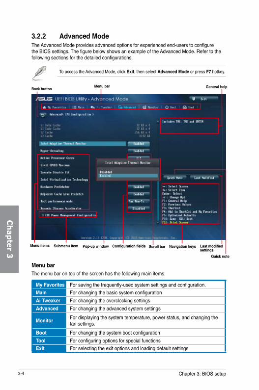
3-4 Chapter 3: BIOS setup
Ch
apter 3
3.2.2 Advanced ModeThe Advanced Mode provides advanced options for experienced end-users to configure the BIOS settings. The figure below shows an example of the Advanced Mode. Refer to the following sections for the detailed configurations.
To access the Advanced Mode, click Exit, then select Advanced Mode or press F7 hotkey.
Menu barThe menu bar on top of the screen has the following main items:
My Favorites For saving the frequently-used system settings and configuration.Main For changing the basic system configurationAi Tweaker For changing the overclocking settingsAdvanced For changing the advanced system settings
Monitor For displaying the system temperature, power status, and changing the fan settings.
Boot For changing the system boot configurationTool For configuring options for special functionsExit For selecting the exit options and loading default settings
Navigation keysConfiguration fields
Back button Menu bar
General help
Submenu itemMenu items Pop-up window Scroll bar Last modified settings
Quick note

ASUS P9D WS 3-5
Ch
apte
r 3
Menu itemsThe highlighted item on the menu bar displays the specific items for that menu. For example, selecting Main shows the Main menu items.The other items (Ai Tweaker, Advanced, Monitor, Boot, Tool, and Exit) on the menu bar have their respective menu items.
Back buttonThis button appears when entering a submenu. Press <Esc> or use the USB mouse to click this button to return to the previous menu screen.
Submenu itemsA greater than sign (>) before each item on any menu screen means that the item has a submenu. To display the submenu, select the item and press <Enter>.
Pop-up windowSelect a menu item and press <Enter> to display a pop-up window with the configuration options for that item.
Scroll barA scroll bar appears on the right side of a menu screen when there are items that do not fit on the screen. Press the Up/Down arrow keys or <Page Up> / <Page Down> keys to display the other items on the screen.
Navigation keysAt the bottom right corner of the menu screen are the navigation keys for the BIOS setup program. Use the navigation keys to select items in the menu and change the settings.
If you delete all shortcut items from the F3: Shortcut list, the default shortcut items will reappear after your next startup.
General helpAt the top right corner of the menu screen is a brief description of the selected item. Use <F12> key to capture the BIOS screen and save it to the removable storage device.
Configuration fieldsThese fields show the values for the menu items. If an item is user-configurable, you can change the value of the field opposite the item. You cannot select an item that is not user-configurable.A configurable field is highlighted when selected. To change the value of a field, select it and press <Enter> to display a list of options.
Quick Note buttonThis button allows you to enter notes of the activities that you have done in BIOS.
• The Quick Note function does not support the following keyboard functions: delete, cut, copy and paste.
• You can only use the alphanumeric characters to enter your notes.

3-6 Chapter 3: BIOS setup
Ch
apter 3
3.3 My FavoritesMyFavorites is your personal space where you can easily save and access your favorite BIOS items.
Last Modified buttonThis button shows the items that you last modified and saved in BIOS Setup.
Adding items to My FavoritesTo add frequently-used BIOS items to My Favorites:
1. Use the arrow keys to select an item that you want to add. When using a mouse, hover the pointer to the item.
2. Press <F4> on your keyboard or right-click on your mouse to add the item to My Favorites page.
You cannot add the following items to My Favorites:
• Items with submenu options
• User-configurable items such as language and boot device order
• Configuration items such as Memory SPD Information, system time and date

ASUS P9D WS 3-7
Ch
apte
r 3
3.4 Main menuThe Main menu screen appears when you enter the Advanced Mode of the BIOS Setup program. The Main menu provides you an overview of the basic system information, and allows you to set the system date, time, language, and security settings.
SecurityThe Security menu items allow you to change the system security settings.
• If you have forgotten your BIOS password, erase the CMOS Real Time Clock (RTC) RAM to clear the BIOS password. See section 1.2.6 Onboard buttons and switches for information on how to erase the RTC RAM via the Clear CMOS button.
• The Administrator or User Password items on top of the screen show the defaultThe Administrator or User Password items on top of the screen show the default [Not Installed]. After you set a password, these items show [Installed].

3-8 Chapter 3: BIOS setup
Ch
apter 3
Administrator PasswordIf you have set an administrator password, we recommend that you enter the administrator password for accessing the system. Otherwise, you might be able to see or change only selected fields in the BIOS setup program.
To set an administrator password:
1. Select the Administrator Password item and press <Enter>.
2. From the Create New Password box, key in a password, then press <Enter>.
3. Confirm the password when prompted.
To change an administrator password:
1. Select the Administrator Password item and press <Enter>.
2. From the Enter Current Password box, key in the current password, then press <Enter>.
3. From the Create New Password box, key in a new password, then press <Enter>.
4. Confirm the password when prompted.To clear the administrator password, follow the same steps as in changing an administrator password, but press <Enter> when prompted to create/confirm the password. After you clear the password, the Administrator Password item on top of the screen shows Not Installed.
User PasswordIf you have set a user password, you must enter the user password for accessing the system. The User Password item on top of the screen shows the default Not Installed. After you set a password, this item shows Installed.
To set a user password:
1. Select the User Password item and press <Enter>.
2. From the Create New Password box, key in a password, then press <Enter>.
3. Confirm the password when prompted.

ASUS P9D WS 3-9
Ch
apte
r 3
To change a user password:
1. Select the User Password item and press <Enter>.
2. From the Enter Current Password box, key in the current password, then press <Enter>.
3. From the Create New Password box, key in a new password, then press <Enter>.
4. Confirm the password when prompted.To clear the user password, follow the same steps as in changing a user password, but press <Enter> when prompted to create/confirm the password. After you clear the password, the User Password item on top of the screen shows Not Installed.
3.5 Ai Tweaker menuThe Ai Tweaker menu items allow you to configure overclocking-related items.
Be cautious when changing the settings of the Ai Tweaker menu items. Incorrect field values can cause the system to malfunction.
The configuration options for this section vary depending on the CPU and DIMM model you installed on the motherboard.
Scroll down to display other BIOS items.
3-10 Chapter 3: BIOS setup
Ch
apter 3
Ai Overclock Tuner [Auto]Allows you to select the CPU overclocking options to achieve the desired CPU internal frequency. Select any of these preset overclocking configuration options:[Auto] Loads the optimal settings for the system.[X.M.P.] Allows your system to automatically optimize the CPU ratio, BCLK
frequency, and memory parameters. If you install memory modules supporting the eXtreme Memory Profile (X.M.P.) Technology, select this item to set the profiles supported by your memory modules for optimizing the system performance.
The following item appears only when you set the Ai Overclocking Tuner to [X.M.P.].
eXtreme Memory ProfileAllows you to select the X.M.P. mode supported by your memory module.Configuration options: [Profile #1] [Profile #2]
ASUS MultiCore Enhancement [Enabled][Enabled] Default set to [Enabled] for maximum performance under XMP/Manual/
User-defined memory frequency mode.[Disabled] Allows you to set to default core ratio settings.
CPU Core Ratio [Auto]Allows you to set the CPU ratio and synchronize automatically either per core or all cores.Configuration options: [Auto] [Sync All Cores] [Per Core]
When the CPU Core Ratio is set to [Per Core], the following item appears:
1-Core Ratio Limit [Auto]Select [Auto] to apply the CPU default Turbo Ratio setting or manually assign a 1-Core Limit value that must be higher than or equal to the 2-Core Ratio Limit.2-Core Ratio Limit [Auto]Select [Auto] to apply the CPU default Turbo Ratio setting or manually assign a 2-Core Limit value that must be higher than or equal to the 3-Core Ratio Limit.
If you assign a value for 2-Core Ratio Limit, do not set the 1-Core Ratio Limit to [Auto].
3-Core Ratio Limit [Auto]Select [Auto] to apply the CPU default Turbo Ratio setting or manually assign a 3-Core Limit value that must be higher than or equal to the 4-Core Ratio Limit.
If you assign a value for 3-Core Ratio Limit, do not set the 1-Core Ratio Limit and 2-Core Ratio Limit to [Auto].

ASUS P9D WS 3-11
Ch
apte
r 3
4-Core Ratio Limit [Auto]Select [Auto] to apply the CPU default Turbo Ratio setting or manually assign a 4-Core Limit value that must be higher than or equal to the 3-Core Ratio Limit.
If you assign a value for 4-Core Ratio Limit, do not set the 1-Core Ratio Limit, 2-Core Ratio Limit, and 3-Core Ratio to [Auto].
Min CPU Cache Ratio [Auto]Allows you to set the minimum possible ratio on the Uncore part of the processor. Use the <+> or <-> keys to adjust the value. The values depend on the CPU installed.
Max CPU Cache Ratio [Auto]Allows you to set the maximum possible ratio on the Uncore part of the processor. Use the <+> or <-> keys to adjust the value. The values depend on the CPU installed.
Memory Frequency [Auto]Allows you to set the memory operating frequency. The configuration options vary with the BCLK/PCIE Frequency item settings.
CPU Graphics Max. Ratio [Auto]Allows you to optimize the CPU Graphics Ratio depending on the system loading. Use the <+> or <-> keys to adjust the value.
EPU Power Saving Mode [Disabled]Allows you to enable or disable the EPU power saving function.Configuration options: [Disabled] [Enabled]
DRAM Timing ControlThe subitems in this menu allow you to set the DRAM timing control features. Use the <+> or <-> keys to adjust the value. To restore the default setting, type [auto] using the keyboard and press the <Enter> key.
Changing the values in this menu may cause the system to become unstable! If this happens, revert to the default settings.

3-12 Chapter 3: BIOS setup
Ch
apter 3
Primary Timings
DRAM CAS# Latency [Auto]Configuration options: [Auto] [1] – [31]DRAM RAS# to CAS# Delay [Auto]Configuration options: [Auto] [1] – [31]DRAM RAS# PRE Time [Auto]Configuration options: [Auto] [1] – [31]DRAM RAS# ACT Time [Auto]Configuration options: [Auto] [1] – [63]DRAM Command Rate [Auto]Configuration options: [Auto] [1] – [3]
Secondary Timings
DRAM RAS# to RAS# Delay [Auto]Configuration options: [Auto] [1] – [15]DRAM REF Cycle Time [Auto]Configuration options: [Auto] [1] – [511]DRAM Refresh Interval [Auto]Configuration options: [Auto] [1] – [65535]DRAM WRITE Recovery Time [Auto]Configuration options: [Auto] [1] – [16]DRAM READ to PRE Time [Auto]Configuration options: [Auto] [1] – [15]DRAM FOUR ACT WIN Time [Auto]Configuration options: [Auto] [1] – [255]DRAM WRITE to READ Delay [Auto]Configuration options: [Auto] [1] – [15]DRAM CKE Minimum pulse width [Auto]Configuration options: [Auto] [1] – [15]DRAM CAS# Write Latency [Auto]Configuration options: [Auto] [1] – [31]RTL IOL control
DRAM RTL initial Value [Auto]Configuration options: [Auto] [1] - [63]DRAM RTL (CHA_R0D0) [Auto]Configuration options: [Auto] [1] - [63]DRAM RTL (CHA_R0D1) [Auto]Configuration options: [Auto] [1] - [63]
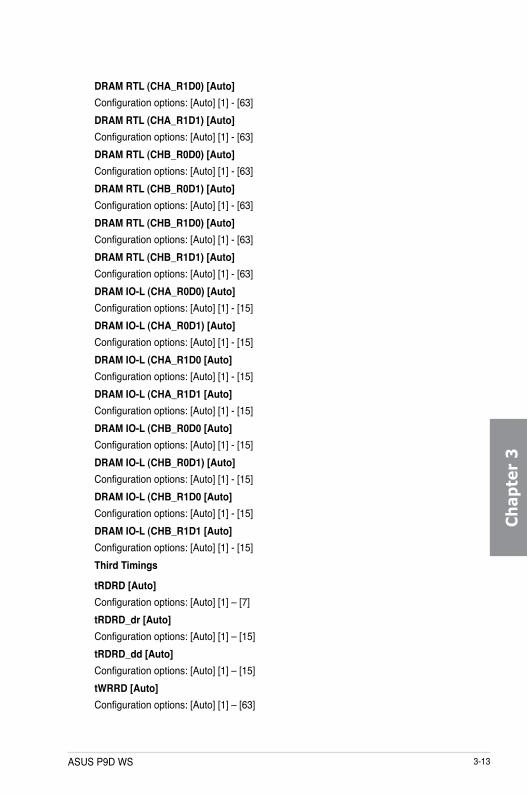
ASUS P9D WS 3-13
Ch
apte
r 3
DRAM RTL (CHA_R1D0) [Auto]Configuration options: [Auto] [1] - [63]DRAM RTL (CHA_R1D1) [Auto]Configuration options: [Auto] [1] - [63]DRAM RTL (CHB_R0D0) [Auto]Configuration options: [Auto] [1] - [63]DRAM RTL (CHB_R0D1) [Auto]Configuration options: [Auto] [1] - [63]DRAM RTL (CHB_R1D0) [Auto]Configuration options: [Auto] [1] - [63]DRAM RTL (CHB_R1D1) [Auto]Configuration options: [Auto] [1] - [63]DRAM IO-L (CHA_R0D0) [Auto]Configuration options: [Auto] [1] - [15]DRAM IO-L (CHA_R0D1) [Auto]Configuration options: [Auto] [1] - [15]DRAM IO-L (CHA_R1D0 [Auto]Configuration options: [Auto] [1] - [15]DRAM IO-L (CHA_R1D1 [Auto]Configuration options: [Auto] [1] - [15]DRAM IO-L (CHB_R0D0 [Auto]Configuration options: [Auto] [1] - [15]DRAM IO-L (CHB_R0D1) [Auto]Configuration options: [Auto] [1] - [15]DRAM IO-L (CHB_R1D0 [Auto]Configuration options: [Auto] [1] - [15]DRAM IO-L (CHB_R1D1 [Auto]Configuration options: [Auto] [1] - [15]Third Timings
tRDRD [Auto]Configuration options: [Auto] [1] – [7]tRDRD_dr [Auto]Configuration options: [Auto] [1] – [15]tRDRD_dd [Auto]Configuration options: [Auto] [1] – [15]tWRRD [Auto]Configuration options: [Auto] [1] – [63]

3-14 Chapter 3: BIOS setup
Ch
apter 3
tWRRD_dr [Auto]Configuration options: [Auto] [1] – [15]tWRRD_dd [Auto]Configuration options: [Auto] [1] – [15]tWRWR [Auto]Configuration options: [Auto] [1] – [7]tWRWR_dr [Auto]Configuration options: [Auto] [1] – [15]tWRWR_dd [Auto]Configuration options: [Auto] [1] – [15]Dec_WRD [Auto]Configuration options: [Auto] [0] – [1]tRDWR [Auto]Configuration options: [Auto] [1] – [31]tRDWR_dr [Auto]Configuration options: [Auto] [1] – [31]tRDWR_dd [Auto]Configuration options: [Auto] [1] – [31]
MISC
MRC Fast Boot [Auto]Allows you to enable, disable or automatically set the MRC fast boot.Configuration options: [Auto] [Enable] [Disable]DRAM CLK Period [Auto]Configuration options: [Auto] [1] – [14]Channel A DIMM Control [Enable Bot...]Configuration options: [Enable Both DIMMS] [Disable DIMM0] [Disable DIMM1] [Disable Both DIMMS]Channel B DIMM Control [Enable Bot...]Configuration options: [Enable Both DIMMS] [Disable DIMM0] [Disable DIMM1] [Disable Both DIMMS]Scrambler Setting [Optimized ...]Allows you to set the optimized scrambler setting for stability.Configuration options: [Optimized (ASUS)] [Default (MRC)]
ASUS P9D WS 3-15
Ch
apte
r 3
DIGI+ Power ControlCPU Load-Line Calibration [Auto]Load-line is defined by Intel® VRM specification and affects CPU power voltage. The CPU working voltage will decrease proportionally to CPU loading. Higher load-line calibration could get higher voltage and good overclocking performance, but increases the CPU and VRM thermal conditions.Select from Level 1 to Level 8 to adjust CPU power voltage from 0% to 100%.
The actual performance boost may vary depending on your CPU specification.
DO NOT remove the thermal module. The thermal conditions should be monitored.
CPU Voltage Frequency [Auto]Frequency switching affects the VRM transient response and the thermal component conditions. Higher frequency gets quicker transient response. Configuration options: [Auto] [Manual]
DO NOT remove the thermal module when setting this item to [Manual Mode]. The thermal conditions should be monitored.
The following item appears only when you set the CPU Voltage Frequency to [Manual].
CPU Fixed Frequency [500]This item allows you to set a fixed CPU Voltage frequency. Use the <+> or <-> keys to adjust the value. The values range from 300kHz to 500kHz with a 50kHz interval.

3-16 Chapter 3: BIOS setup
Ch
apter 3
CPU Power Phase Control [Auto]Allows you to set the power phase control of the CPU.Configuration options: [Auto] [Standard] [Optimized] [Extreme] [Manual Adjustment]
DO NOT remove the thermal module when setting this item to [Extreme] and [Manual Adjustment]. The thermal conditions should be monitored.
The following item appears only when you set the CPU Power Phase Control to [Manual Adjustment].
Manual Adjustment [Fast]Allows you to set a faster phase response for the CPU to increase system performance or to slower phase response to decrease DRAM power efficiency.Configuration options: [Ultra Fast] [Fast] [Medium] [Regular]
CPU Power Duty Control [T.Probe]DIGI + VRM Duty Control adjusts the current of every VRM phase and the thermal conditions of every phase component. [T. Probe] Select to maintain the VRM thermal balance.[Extreme] Select to maintain the current VRM balance.
DO NOT remove the thermal module. The thermal conditions should be monitored.
CPU Current Capability [Auto]DIGI+ VRM CPU Current Capability provides wider total power range for overclocking. A higher value setting gets higher VRM power consumption delivery and extends the overclocking frequency range simultaneously. Configuration options: [Auto] [100%] [110%] [120%] [130%] [140%]
Choose a higher value when overclocking, or under a high CPU loading for extra power support.
CPU Power Thermal Control [120]A higher temperature brings a wider CPU power thermal range and extends the overclocking tolerance to enlarge the O.C. potential. Use the <+> or <-> keys to adjust the value. The values depend on the CPU installed.
DO NOT remove the thermal module. The thermal conditions should be monitored.

ASUS P9D WS 3-17
Ch
apte
r 3
DRAM Current Capability [100%]A higher value brings a wider total power range, and extends the overclocking range simultaneously. Configuration options: [100%] [110%] [120%] [130%] [140%]DRAM Voltage Frequency [Auto]Allows you to adjust the DRAM switching frequency. Assign a fixed high DRAM frequency to increase the O.C. range, or a low DRAM frequency for a better system stability. Configuration options: [Auto] [Manual]
The following item appears only when you set set the DRAM Frequency Mode item to [Manual].
DRAM Fixed Frequency Mode [500]Allows you to set a fixed DRAM frequency to increase the overclocking range or a low DRAM frequency for better system stability. Use the <+> or <-> keys to adjust the value. The values range from 400kHz to 500kHz with a 50kHz interval.
DRAM Power Phase Control [Standard][Standard] Allows you to set the Standard mode.[Optimized] Allows you to set the ASUS optimized phase tuning profile.[Extreme] Allows you to set the full phase mode.[Manual Adjustment] Allows you to adjust the DRAM Power Phase Control manually.
The following item appears only when you set the CPU Power Phase Control to [Manual Adjustment].
Manual Adjustment [Fast]Allows you to set a faster phase response for the DRAM to increase system performance or to slower phase response to decrease DRAM power efficiency.Configuration options: [Ultra Fast] [Fast] [Medium] [Regular]
CPU Power ManagementThe subitems in this menu allow you to set the CPU ratio and their features.
Enhanced Intel SpeedStep Technology [Enabled]Allows the operating system to dynamically adjust the processor voltage and cores frequency, resulting to a decreased average power consumption and decreased average heat production.Configuration options: [Disabled] [Enabled]Turbo Mode [Enabled]Allows you to enable your core processor’s speed to run faster than the base operating frequency when it is below operating power, current and temperature specification limit. Configuration options: [Disabled] [Enabled]
The following items appear only when you set the Turbo Mode to [Enabled].

3-18 Chapter 3: BIOS setup
Ch
apter 3
Turbo Mode Parameters
Long Duration Package Power Limit [Auto]Allows you to limit the Turbo Ratio’s time duration that exceeds the TDP (Thermal Design Power) for maximum performance. Use the <+> or <-> keys to adjust the value. The values range from 1W t0 4096W.Package Power Time Window [Auto]Also known as Power Limit 1, and allows you to maintain the time window for Turbo Ratio over TDP (Thermal Design Power). Use the <+> or <-> keys to adjust the value. The values range from 1 to 127 in seconds.Short Duration Package Power Limit [Auto]Also known as Power Limit 2, and allows you to provide rapid protection when the package power exceeds the Power Limit 1. Use the <+> or <-> keys to adjust the value. The values range from 1W t0 4096W.CPU Integrated VR Current Limit [Auto]Allows you to set a higher current limit to prevent frequency and power throttling when overclocking. Use the <+> or <-> keys to adjust the value. The values range from 0.125 to 1023.875 with a 0.125 interval.
CPU Internal Power Switching Frequency
Frequency Tuning Mode [Auto]Allows you to increase or decrease the switching frequency of the internal regulator. Decrease to help consume less power or increase to help votlage stability. When this item is set to [+] or [-], the Frequency Tuning Offset appears and allows you to set its value from 0% to 6%.
CPU Internal Power Fault Control
Thermal Feedback [Auto]Allows your system to take precautionary actions to be taken by the CPU when the thermal conditions of the external regulator exceeds the threshold.Configuration options: [Auto] [Disabled] [Enabled]CPU Integrated VR Fault Management [Auto]Disable this item to prevent tripping the Fully Integrated Voltage Regulator when doing over-voltage. We recommend you to disable this item when overclocking.Configuration options: [Auto] [Disabled] [Enabled]
CPU Internal Power Configuration
CPU Integrated VR Efficiency Management [Auto]Allows you to improve power saving when the processor is in low power state. Disable to make the Fully Integrated Voltage Regulator work in high performance at all times.Configuration options: [Auto] [High Performance] [Balanced]

ASUS P9D WS 3-19
Ch
apte
r 3
Power Decay Mode [Auto]Allows your system to improve the power saving mode on the Fully Integrated Voltage Regulator as the processor goes into low current state.Configuration options: [Auto] [Disabled] [Enabled]Idle Power-in Response [Auto]Allows you to set the slew rate for the Fully Integrated Voltage Regulator as it enters manual override mode.Configuration options: [Auto] [Regular] [Fast]Idle Power-out Response [Auto]Allows you to set the slew rate for the Fully Integrated Voltage Regulator as it exits manual override mode.Configuration options: [Auto] [Regular] [Fast]Power Current Slope [Auto]Allows you to set the gradient of the high-speed active phase current balance during load transients to eliminate current imbalance that can result from a load current oscillating near the switching frequency.Configuration options: [Auto] [LEVEL 4] [LEVEL 3] [LEVEL 2] [LEVEL 1] [LEVEL 0] [LEVEL -1] [LEVEL -2] [LEVEL -3] [LEVEL -4]Power Current Offset [Auto]Allows you to increase or decrease the output current sensed by the CPU. It finds the balance between optimal regulating while staying below the current threshold.Configuration options: [Auto] [100%] [87.5%] [75.0%] [62.5%] [50.0%] [37.5%] [25.0%] [12.5%] [0%] [-12.5%] [-25.0%] [-37.5%] [-50.0%] [-62.5%] [-75.0%] [-87.5%] [-100%]Power Fast Ramp Response [Auto]Allows you to increase to enhance the response of the voltage regulator during the load transient.Configuration options: [Auto] [0.00] - [1.50]
CPU Internal Power Saving Control
Power Saving Level 1 Threshold [Auto]Lower value provides sufficient overclocking tolerance to enlarge the overclocking potential. Higher value provides better power-saving condition.Use <+> or <-> key to adjust the value. The values range from 0A to 80A at 1Amp increment.Power Saving Level 2 Threshold [Auto]Lower value provides sufficient overclocking tolerance to enlarge the overclocking potential. Higher value provides better power-saving condition.Use <+> or <-> key to adjust the value. The values range from 0A to 50A at 1Amp increment.Power Saving Level 3 Threshold [Auto]Lower value provides sufficient overclocking tolerance to enlarge the overclocking potential. Higher value provides better power-saving condition.Use <+> or <-> key to adjust the value. The values range from 0A to 30A at 1Amp increment.

3-20 Chapter 3: BIOS setup
Ch
apter 3
CPU Core Voltage [Auto]Allows you to configure the amount of voltage fed to the cores of the processor. Increase the amount of voltage when increasing core frequency.Configuration options: [Auto] [Manual Mode] [Offset Mode] [Adaptive Mode]
• The Adaptive Mode option appears only if you are using an Intel® Core™ i3 series processors.
• The following item appears only when you set the CPU Core Voltage to [Manual].
CPU Core Voltage Override [Auto]Allows you to set the CPU Core Voltage override. Use the <+> or <-> keys to adjust the value, The values range from 0.001V to 1.920V with a 0.001V interval.
The following items appear only when you set the CPU Core Voltage to [Offset Mode].
Offset Mode Sign [+][+] To offset the voltage by a positive value.[–] To offset the voltage by a negative value.
CPU Core Voltage OffsetUse the <+> or <-> keys to adjust the value. The values range from 0.001V to 0.999V with a 0.001V interval.
CPU Cache Voltage [Auto]Allows you to configure the amount of voltage fed to the uncore of the processor including its cache. Increase the voltage when increasing Ring frequency.Configuration options: [Auto] [Manual Mode] [Offset Mode] [Adaptive Mode]
• The Adaptive Mode option appears only if you are using an Intel® Core™ i3 series processors.
• The following item appears only when you set the CPU Cache Voltage to [Manual Mode].
CPU Cache Voltage Override [Auto]Allows you to set the CPU Cache Voltage override. Use the <+> or <-> keys to adjust the value, The values range from 0.001V to 1.920V with a 0.001V interval.
The following items appear only when you set the CPU Core Voltage to [Offset Mode].

ASUS P9D WS 3-21
Ch
apte
r 3
Offset Mode Sign [+][+] To offset the voltage by a positive value.[–] To offset the voltage by a negative value.
CPU Cache Voltage OffsetAllows you to set the CPU cache voltage offset. Use the <+> or <-> keys to adjust the value. The values range from 0.001V to 0.999V with a 0.001V interval.
CPU Graphics Voltage [Auto]Allows you to configure the amount of voltage fed to the onboard graphics unit on the processor. Increase the amount of voltage when increasing iGPU frequency.Configuration options: [Auto] [Manual Mode] [Offset Mode] [Adaptive Mode]
The following item appears only when you set the CPU Core Voltage to [Manual].
CPU Graphics Voltage Override [Auto]Allows you to set the CPU Graphics Voltage override. Use the <+> or <-> keys to adjust the value, The values range from 0.001V to 1.920V with a 0.001V interval.
The following items appear only when you set the CPU Core Voltage to [Offset Mode] or [Adaptive Mode].
Offset Mode Sign [+][+] To offset the voltage by a positive value.[–] To offset the voltage by a negative value.
CPU Graphics Voltage OffsetUse the <+> or <-> keys to adjust the value. The values range from 0.001V to 0.999V with a 0.001V interval.
The following item appears only when you set the CPU Core Voltage to [Adaptive Mode].
Additional Turbo Mode CPU Graphics Voltage [Auto]This item allows you to add voltage for Turbo Mode CPU Graphics. Use the <+> or <-> keys to adjust the value. The values range from 0.001V to 1.920V with a 0.001V interval.

3-22 Chapter 3: BIOS setup
Ch
apter 3
CPU System Agent Voltage Offset Mode Sign [+][+] To offset the voltage by a positive value.[–] To offset the voltage by a negative value.
CPU System Agent Voltage Offset [Auto]Allows you to configure the amount of voltage fed to the system agent of the processor including its PCIe controller and power control unit. Increase the amount of voltage when increasing DRAM frequency. Use the <+> or <-> keys to adjust the value. The values range from 0.001V to 0.999V with a 0.001V interval.
CPU Analog I/O Voltage Offset Mode Sign [+][+] To offset the voltage by a positive value.[–] To offset the voltage by a negative value.
CPU Analog I/O Voltage Offset [Auto]Allows you to configure the amount of voltage fed to the analog portion of the I/O on the processor. Increase the amount of voltage when increasing DRAM frequency. Use the <+> or <-> keys to adjust the value. The values range from 0.001V to 0.999V with a 0.001V interval.
CPU Digital I/O Voltage Offset Mode Sign [+][+] To offset the voltage by a positive value.[–] To offset the voltage by a negative value.
CPU Digital I/O Voltage Offset [Auto]Allows you to configure the amount of voltage fed to the digital portion of the I/O on the processor. Increase the amount of voltage when increasing DRAM frequency. Use the <+> or <-> keys to adjust the value. The values range from 0.001V to 0.999V with a 0.001V interval.
CPU Input Voltage [Auto]Allows you to set an input voltage for the processor by the external voltage regulator. By default, this item takes the standard value of the installed CPU. You can use the <+> or <-> keys to adjust the value. The values range from 0.800V to 2.40V with a 0.010V interval.
DRAM Voltage [Auto]Allows you to set the DRAM voltage. You can use the <+> or <-> keys to adjust the value. The values range from 1.20V to 1.80V with a 0.005V interval.
According to Intel® CPU specifications, DIMMs with voltage requirement over 1.65V may damage the CPU permanently. We recommend that you install the DIMMs with the voltage requirement below 1.65V.
DRAM CTRL REF Voltage [Auto]This item is the DRAM reference voltage for the control lines from the memory bus. You can use the <+> or <-> keys to adjust the value. The values range from 0.3950x to 0.6300x with a 0.0050x interval.

ASUS P9D WS 3-23
Ch
apte
r 3
DRAM DATA REF Voltage on CHA [Auto]This item is the DRAM reference voltage for the data lines on Channels A and B. You can use the <+> or <-> keys to adjust the value. The values range from 0.395x to 0.630x with a 0.005x interval.
DRAM DATA REF Voltage on CHB [Auto]This item is the DRAM reference voltage for the data lines on Channels A and B. You can use the <+> or <-> keys to adjust the value. The values range from 0.395x to 0.630x with a 0.005x interval.
CPU Spread Spectrum [Auto][Auto] Automatic configuration.[Disabled] Disable CPU Clock Spectrum.[Enabled] Enable CPU Clock Spectrum.

3-24 Chapter 3: BIOS setup
Ch
apter 3
3.6 Advanced menuThe Advanced menu items allow you to change the settings for the CPU and other system devices.
Be cautious when changing the settings of the Advanced menu items. Incorrect field values can cause the system to malfunction.

ASUS P9D WS 3-25
Ch
apte
r 3
3.6.1 CPU ConfigurationThe items in this menu show the CPU-related information that the BIOS automatically detects.
The items in this menu may vary based on the CPU installed.
Intel Adaptive Thermal Monitor [Enabled][Enabled] Enables the overheated CPU to throttle its clock speed to cool down.[Disabled] Disables the CPU thermal monitor function.
Hyper-threading [Enabled]The Intel Hyper-Threading Technology allows a hyper-threading processor to appear as two logical processors to the operating system, allowing the operating system to schedule two threads or processes simultaneously.[Enabled] Two threads per activated core are enabled.[Disabled] Only one thread per activated core is enabled.
This Item apears only if you installed a CPU that supports the Intel Hyper-threading technology.

3-26 Chapter 3: BIOS setup
Ch
apter 3
Active Processor Cores [All]Allows you to choose the number of CPU cores to activate in each processor package.Configuration options: [All] [1] [2] [3]
Limit CPUID Maximum [Disabled][Enabled] Allows legacy operating systems to boot even without support for CPUs
with extended CPUID functions.[Disabled] Disables this function.
Execute Disable Bit [Enabled][Enabled] Enables the No-Execution Page Protection Technology.[Disabled] Forces the XD feature flag to always return to zero (0).
Intel Virtualization Technology [Disabled][Enabled] Allows a hardware platform to run multiple operating systems separately
and simultaneously, enabling one system to virtually function as several systems.
[Disabled] Disables this function.
Hardware Prefetcher [Enabled][Enabled] Allows a hardware platform to automatically analyze the requirements and
prefetch data and codes for the CPU.[Disabled] Disables this function.
Adjacent Cache Line Prefetch [Enabled][Enabled] Allows a hardware platform to perform adjacent cache line prefetching.[Disabled] Disables this function.
Boot performance mode [Max Non-Turbo Performance]Allows you to select the boot performance before entering the OS.Configuration options: [Max Non-Turbo Performance] [Max Battery] [Turbo Performance]
Dynamic Storage Accelerator [Disabled]Allows you to enable or disable Dynamic Storage Accelerator for C state configuration.Configuration options: [Enabled] [Disabled]
CPU Power Management ConfigurationThis item allows you to manage and configure the CPU’s power.
Enhanced Intel SpeedStep Technology [Enabled]Allows your system to adjust the processor’s voltage and cores frequency, resulting in decreased power consumption and heat production.[Disabled] The CPU runs at its default speed.[Enabled] The system controls the CPU speed.

ASUS P9D WS 3-27
Ch
apte
r 3
Turbo Mode [Enabled]Allows you to set the processor cores to run faster than the base frequency when operating below power, current and temperature specification limit.Configuration options: [Enabled] [Disabled]CPU C States [Auto]Allows you to enable or disable the CPU C states.Configuration options: [Auto] [Enabled] [Disabled]
The following items appear only when you set the CPU C States to [Enabled].
Enhanced C1 state [Enabled]Allows your processor to reduce power when the system is in idle mode.Configuration options: [Enabled] [Disabled]CPU C3 Report [Enabled]Allows you to disable or enable the CPU C3 report to the operating system.Configuration options: [Enabled] [Disabled]CPU C6 Report [Enabled]Allows you to disable or enable the CPU C6 report to the operating system.Configuration options: [Enabled] [Disabled]C6 Latency [Short]Allows you to set the duration of C6 latency for C6 state.Configuration options: [Short] [Long]CPU C7 Report [CPU C7s] Report [CPU C7s]Allows you to disable or enable the CPU C7 report to the operating system.Configuration options: [Disabled] [CPU C7] [CPU C7s]C7 Latency [Long]Allows you to set the duration of C7 latency for C7 state.Configuration options: [Short] [Long]Package C State Support [Auto]Allows you to set the a C-state according to the following configuration options: [Auto] [Enabled] [C0/C1] [C2] [C3] [C6] [CPU C7] [CPU C7s]

3-28 Chapter 3: BIOS setup
Ch
apter 3
3.6.2 PCH Configuration
PCI Express ConfigurationAllows you to configure the PCI Express slots.
DMI Link ASPM Control [Auto]Allows you to control the ASPM (Active State Power Management) on both Northbridge side and Southbridge side of the DMI Link.Configuration options: [Disabled] [Enabled] [Auto]ASPM Support [Disabled]Allows you to set the ASPM level.Configuration options: [Disabled] [Auto] [L0s] [L1] [L0sL1]PCIe Speed [Auto]Allows you to select the PCI Express port speed.Configuration options: [Auto] [Gen1] [Gen2]
Intel Rapid Start Technology [Disabled]Allows you to enable or disable Intel® Rapid Start Technology.Configuration options: [Enabled] [Disabled]
The following items appear only when you set the Intel® Rapid Start Technology to [Enabled].
Entry on S3 RTC Wake [Enabled]The system automatically wakes up and set to Rapid Start Technology S3 mode.Configuration options: [Enabled] [Disabled
Entry After [0]Allows you to set the RTC wake-up timer at S3 entry. The time ranges from 0 minute (immediately) to 120 minutes.
Active Page Threshold Support [Enabled]The system automatically goes into sleep mode when the partition size is not enough for the Intel® Rapid Start Technology to work.Configuration options: [Enabled] [Disabled]

ASUS P9D WS 3-29
Ch
apte
r 3
Active Memory Threshold [0]Key in the value for the additional partition size for Rapid Start Technology to work.
Ensure that the caching partition size is larger than the total memory size.
Hybrid Hard Disk Support [Disabled]Allows you to enable or disable the hybrid hard disk support.Configuration options: [Enabled] [Disabled]
Intel Smart Connect Technology [Disabled]Allow you to enable or disable the Intel® Smart Connect Technology.Configuration options: [Enabled] [Disabled]
3.6.3 SATA ConfigurationWhile entering Setup, the BIOS automatically detects the presence of SATA devices. The SATA Port items show Not Present if no SATA device is installed to the corresponding SATA port.Scroll down to display the other BIOS items.

3-30 Chapter 3: BIOS setup
Ch
apter 3
SATA Mode Selection [AHCI]Allows you to set the SATA configuration.[Disabled] Disables the SATA function.[IDE] Set to [IDE Mode] when you want to use the Serial ATA hard disk drives as
Parallel ATA physical storage devices.[AHCI] Set to [AHCI Mode] when you want the SATA hard disk drives to use the
AHCI (Advanced Host Controller Interface). The AHCI allows the onboard storage driver to enable advanced Serial ATA features that increases storage performance on random workloads by allowing the drive to internally optimize the order of commands.
[RAID] Set to [RAID Mode] when you want to create a RAID configuration from the SATA hard disk drives.
Aggressive LPM Support [Auto]Allows you to enable the PCH to aggressively enter link power state.Configuration options: [Disabled] [Enabled] [Auto][Auto]
S.M.A.R.T. Status Check [Enabled]S.M.A.R.T. (Self-Monitoring, Analysis and Reporting Technology) is a monitor system. When read/write of your hard disk errors occur, this feature allows the hard disk to report warning messages during the POST. Configuration options: [Enabled] [Disabled]
Port 1-6 [Enabled] (SATA6G_1 - SATA6G_6 [Yellow])Allows you to enabled/disabled the SATA Port 1-6. Configuration options: [Disabled] [Enabled]
Hot Plug [Disabled] (SATA6G_1 - SATA6G_6 [Yellow])These items appear only when you set the SATA Mode Selection item to [AHCI] or [RAID], and allow you to enable/disable SATA Hot Plug Support. Configuration options: [Disabled] [Enabled]

ASUS P9D WS 3-31
Ch
apte
r 3
VT-d [Disabled]Allows you to enable virtualization technology function on memory control hub.[Enabled] Enables the function.[Disabled] Disables this function.
This item will appear only if the CPU supports virtualization technology function.
CPU Audio Devices [Enabled]Allows you to enable or disable CPU SA Audio devices.Configuration options: [Enabled] [Disabled]
DVI Port Audio [Enabled]Allows you to enable or disable DVI port Audio.Configuration options: [Enabled] [Disabled]
Graphics ConfigurationAllows you to select a primary display from iGPU, and PCIe graphical devices.
iGPU Multi-Monitor [Disabled]Allows you to enable the iGPU Multi-Monitor. The iGPU shared system memory size will be fixed at 64MB.Configuration options: [Disabled] [Enabled]
DMI ConfigurationAllows you to control various DMI (Desktop Management Interface) functions.
DMI Gen 2 [Auto]Allows you to enable or disable DMI Gen 2. Configuration options: [Auto] [Enabled] [Disabled]
3.6.4 System Agent Configuration

3-32 Chapter 3: BIOS setup
Ch
apter 3
NB PCIe ConfigurationAllows you to configure the NB PCI Express settings.
PCIEx16_1/2/3 Link Speed [Auto]Allows you to configure the PCIEx16 speed.Configuration options: [Auto] [Gen1] [Gen2] [Gen3]DMI Link ASPM Control [Auto]Allows you to enable or disable the control of Active State Power Management on SA side of the DMI Link.Configuration options: [Auto] [Disabled] [L0s] [L1] [L0sL1]PEG - ASPM [Disabled]Allows you to control ASPM support for the PEG device.Configuration options: [Disabled] [Auto] [ASPM L0s] [ASPM L1] [ASPM L0sL1]
Memory ConfigurationAllows you to configure the memory configuration parameters.
ECC Support [Enabled]Allows you to enable or disable the DDR Ecc support.Configuration options: [Enabled] [Disabled]Memory Scrambler [Enabled]Allows you to enable or disable the Memory Scrambler support.Configuration options: [Enabled] [Disabled]Memory Remap [Enabled]Allows you to enable remapping the memory above 4GB.Configuration options: [Enabled] [Disabled]

ASUS P9D WS 3-33
Ch
apte
r 3
3.6.5 USB ConfigurationThe items in this menu allow you to change the USB-related features.
The USB Devices item shows the auto-detected values. If no USB device is detected, the item shows None.
Legacy USB Support [Enabled][Enabled] Enables the support for USB devices on legacy operating systems (OS).[Disabled] The USB devices can be used only for the BIOS setup program. It cannot
be recognized in boot devices list.[Auto] Allows the system to detect the presence of USB devices at startup. If
detected, the USB controller legacy mode is enabled. If no USB device is detected, the legacy USB support is disabled.
Intel xHCI Mode [Smart Auto][Auto] Keeps the last operation of xHCI controller in OS during bootup.[Smart Auto] Enables the operation of xHCI controller.[Enabled] Enables the xHCI controller.[Disabled] Disables the xHCI controller.
EHCI Hand-off [Disabled][Enabled] Enables the support for operating systems without an EHCI hand-off
feature.[Disabled] Disables the EHCI Hand-off support.
USB Single Port ControlAllows you to enable or disable the individual USB port.
Refer to section 1.2.2 Motherboard layout for the location of the USB ports.

3-34 Chapter 3: BIOS setup
Ch
apter 3
3.6.6 Platform Misc ConfigurationThe items in this menu allow you to configure the platform-related features.
PCI Express Native Power Management [Disabled]Allows you to enhance the power saving feature of PCI Express and perform ASPM operations in the operating system.Configuration options: [Disabled] [Enabled]
The following item appears only when you set the PCI Express Native Power Management to [Enabled].
Native ASPM [Disabled][Enabled] Vista controls the ASPM support for the device.[Disabled] BIOS controls the ASPM support for the device.

ASUS P9D WS 3-35
Ch
apte
r 3
3.6.7 Onboard Devices ConfigurationScroll down to view the other BIOS items.
HD Audio Controller [Enabled][Enabled] Enables the High Definition Audio Controller.[Disabled] Disables the controller.
The following items appear only when you set the HD Audio Controller to [Enabled].
Front Panel Type [HD]Allows you to set the front panel audio connector (AAFP) mode to legacy AC’97 or high-definition audio depending on the audio standard that the front panel audio module supports.[HD] Sets the front panel audio connector (AAFP) mode to high definition
audio.[AC97] Sets the front panel audio connector (AAFP) mode to legacy AC’97
SPDIF Out Type [SPDIF][SPDIF] Sets to an SPDIF audio output.[HDMI] Sets to an HDMI audio output.
VIA 1394 Controller [Enabled][Disabled] Disables the controller.[Enabled] Enables the onboard IEEE 1394a controller.
Intel LAN1 Controller [Enabled][Enabled] Enables the Intel® LAN1 controller.[Disabled] Disables the Intel® LAN1 controller.

3-36 Chapter 3: BIOS setup
Ch
apter 3
Intel LAN1 OPROM [Disabled]This item appears only when you set the previous item to [Enabled] and allows you to enable or disable the PXE OptionRom of the Intel LAN1 controller. Configuration options: [Enabled] [Disabled]
Intel LAN2 Controller [Enabled][Enabled] Enables the Intel® LAN2 controller.[Disabled] Disables the Intel® LAN2 controller.
Intel LAN2 OPROM [Disabled]This item appears only when you set the previous item to [Enabled] and allows you to enable or disable the PXE OptionRom of the Intel LAN1 controller. Configuration options: [Enabled] [Disabled]
Serial Port ConfigurationThe sub-items in this menu allow you to set the serial port configuration.
This item only functions if there is a serial port (COM1) connector on the motherboard.
Serial Port [Enabled]Allows you to enable or disable the serial port (COM).Configuration options: [Enabled] [Disabled]Change Settings [IO=3F8h; IRQ=4]Allows you to select the Serial Port base address.Configuration options: [IO=3F8h; IRQ=4] [IO=2F8h; IRQ=3] [IO=3E8h; IRQ=4] [IO=2E8h; IRQ=3]
Parallel Port ConfigurationThe sub-items in this menu allow you to set the parallel port configuration.
Parallel Port [Enabled]Allows you to enable or disable the parallel port (LPT/LPTE). Configuration options: [Enabled] [Disabled]Change Settings [Auto]Allows you to select an optimal setting for the super IO device. Configuration options: [Auto] [IO=378h; IRQ=5] [IO=378h: IRQ=5, 6, 7, 10, 11, 12] [IO=278h; IRQ=5, 6, 7, 10, 11, 12] [IO=3BCh; IRQ=5, 6, 7, 10, 11, 12]Device Mode [STD Printer Mode]Allows you to select the printer port mode. Configuration options: [STD Printer mode] [SPP Mode] [EPP-1.9 and SPP Mode] [EPP-1.7 and SPP Mode] [ECP Mode] [ECP and EPP 1.9 Mode] [ECP and EPP 1.7 Mode]

ASUS P9D WS 3-37
Ch
apte
r 3
ErP Ready [Disabled]Allows you to switch off some power at S4+S5 or S5 to get the system ready for ErP requirement. When set to [Enabled], all other PME options will be switched off.Configuration options: [Disabled] [Enabled (S4+S5)] [Enabled (S5)]
Restore AC Power Loss [Power Off][Power On] The system goes into ON state after an AC power loss.[Power Off] The system goes into OFF state after an AC power loss.[Last State] The system goes into either OFF or ON state, whatever the system state
was before the AC power loss.
Power On By PS/2 Keyboard [Disabled][Disabled] Disables the Power On by a PS/2 keyboard.[Space Bar] Sets the Space Bar on the PS/2 keyboard to turn on the system.[Ctrl-Esc] Sets the Ctrl+Esc key on the PS/2 keyboard to turn on the system. [Power Key] Sets Power key on the PS/2 keyboard to turn on the system. This feature
requires an ATX power supply that provides at least 1A on the +5VSB lead.
Power On By PCIE/PCI [Disabled][Disabled] Disables the PCIE/PCI devices to generate a wake-on-LAN feature of the
Intel®/LAN device or other installed PCIE LAN devices.[Enabled] Enables the PCIE/PCI devices to generate a wake-on-LAN feature of the
Intel®/LAN device or other installed PCIE LAN devices.
Power On By Ring [Disabled][Disabled] Disables Wake-On-Ring from generating a wake event.[Enabled] Enables Wake-On-Ring to generate a wake event.
Power On By RTC [Disabled][Disabled] Disables RTC to generate a wake event.[Enabled] When set to [Enabled], the items RTC Alarm Date (Days) and Hour/
Minute/Second will become user-configurable with set values.
3.6.8 APM

3-38 Chapter 3: BIOS setup
Ch
apter 3
3.6.9 Network Stack
Network Stack [Disable]This item allows user to disable or enable the UEFI network stack.Configuration options: [Disable] [Enable]
The following item appears only when you set the Network Stack to [Enabled].
Ipv4/Ipv6 PXE Support [Enabled]Allows you to enable or disable the Ipv4/Ipv6 PXE boot option.Configuration options: [Disabled] [Enabled]
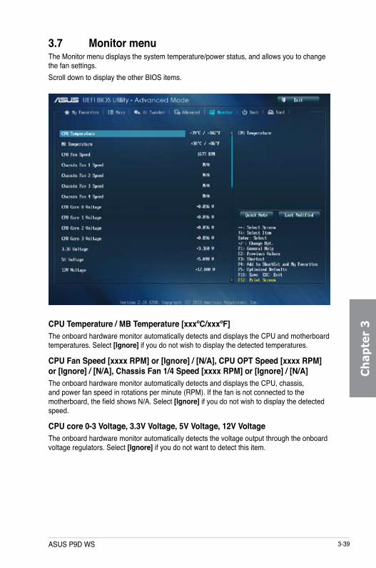
ASUS P9D WS 3-39
Ch
apte
r 3
3.7 Monitor menuThe Monitor menu displays the system temperature/power status, and allows you to change the fan settings.Scroll down to display the other BIOS items.
CPU Temperature / MB Temperature [xxxºC/xxxºF]The onboard hardware monitor automatically detects and displays the CPU and motherboard temperatures. Select [Ignore] if you do not wish to display the detected temperatures.
CPU Fan Speed [xxxx RPM] or [Ignore] / [N/A], CPU OPT Speed [xxxx RPM] or [Ignore] / [N/A], Chassis Fan 1/4 Speed [xxxx RPM] or [Ignore] / [N/A]The onboard hardware monitor automatically detects and displays the CPU, chassis, and power fan speed in rotations per minute (RPM). If the fan is not connected to the motherboard, the field shows N/A. Select [Ignore] if you do not wish to display the detected speed.
CPU core 0-3 Voltage, 3.3V Voltage, 5V Voltage, 12V VoltageThe onboard hardware monitor automatically detects the voltage output through the onboard voltage regulators. Select [Ignore] if you do not want to detect this item.

3-40 Chapter 3: BIOS setup
Ch
apter 3
CPU Q-Fan Control [Enabled]Allows you to set the CPU Q-Fan operating mode.
[Enabled] Enables the CPU Q-Fan control feature.[Disabled] Disables the CPU Q-Fan control feature.
The following items appear only when you set the CPU Q-Fan Control to [Enabled].
CPU Fan Speed Low Limit [300 RPM]Allows you to set the low limit warning for CPU Fan speed. Configuration options: [Ignore] [200 RPM] [300 RPM] [400 RPM] [500 RPM] [600 RPM]CPU Fan Profile [Silent]Allows you to set the appropriate performance level of the CPU fan.[Standard] Set to make the CPU fan adjust automatically depending on the CPU
temperature.[Silent] Set to minimize the fan speed for quiet CPU fan operation.[Turbo] Set to achieve maximum CPU fan speed.[Manual] Set to assign the detailed fan speed control parameters.
The following items appear only when you set the CPU Fan Profile to [Manual].
CPU Upper Temperature [70]Use the <+> or <-> keys to adjust the upper limit of the CPU temperature. The values range from 20ºC to 75ºC. CPU Fan Max. Duty Cycle(%) [100]Use the <+> or <-> keys to adjust the maximum CPU fan duty cycle. The values range from 20% to 100%. When the CPU temperature reaches the upper limit, the CPU fan will operate at the maximum duty cycle.CPU Lower Temperature [20]Use the <+> or <-> keys to adjust the lower limit of the CPU temperature. Displays the lower limit of the CPU temperature.CPU Fan Min. Duty Cycle(%) [20]Use the <+> or <-> keys to adjust the minimum CPU fan duty cycle. The values range from 0% to 100%. When the CPU temperature is under 40ºC, the CPU fan will operate at the minimum duty cycle.
Chassis Q-Fan Control 1/4 [Enabled][Disabled] Disables the Chassis Q-Fan control feature.[Enabled] Enables the Chassis Q-Fan control feature.
The following items appear only when you set the Chassis Q-Fan Control 1/4 to [Enabled].

ASUS P9D WS 3-41
Ch
apte
r 3
Chassis Fan Speed Low Limit 1/4 [300 RPM]This item appears only when you enable the Chassis Q-Fan Control feature and allows you to disable or set the chassis fan warning speed. Configuration options: [Ignore] [200 RPM] [300 RPM] [400 RPM] [500 RPM] [600 RPM]
Chassis Fan 1/4 Profile [Silent]This item appears only when you enable the Chassis Q-Fan Control feature. It allows you to set the appropriate performance level of the chassis fan.[Standard] Set to make the chassis fan adjust automatically depending on the
chassis temperature.[Silent] Set to minimize the fan speed for quiet chassis fan operation.[Turbo] Set to achieve maximum chassis fan speed.[Manual] Set to assign detailed fan speed control parameters.
The following items appear only when you set the Chassis Fan Profile to [Manual].
Chassis Upper Temperature 1/4 [70]Use the <+> or <-> keys to adjust the upper limit of the CPU temperature. The values range from 40ºC to 75ºC. Chassis Fan Max. Duty Cycle(%) 1/4 [100]Use the <+> or <-> keys to adjust the maximum chassis fan duty cycle. The values range from 60% to 100%. When the chassis temperature reaches the upper limit, the chassis fan will operate at the maximum duty cycle.Chassis Lower Temperature 1/4 [40]Use the <+> or <-> keys to adjust the lower limit of the CPU temperature. Displays the lower limit of the CPU temperature.CPU Fan Min. Duty Cycle(%) 1/4 [60]Use the <+> or <-> keys to adjust the minimum chassis fan duty cycle. The values range from 60% to 100%. When the chassis temperature is under 40ºC, the chassis fan will operate at the minimum duty cycle.
Anti Surge Support [Enabled]This item allows you to enable or disable the Anti Surge function.Configuration options: [Disabled] [Enabled]
Dr. Power Policy [Standard]Allows user to select standard or aggressive policy of Dr. Power settings.Configuration options: [Standard] [Aggressive]
The Dr. Power Policy BIOS item appears only if the ASUS Dr. POWER switch is Enabled. Refer to page 2-13 for details.

3-42 Chapter 3: BIOS setup
Ch
apter 3
3.8 Boot menuThe Boot menu items allow you to change the system boot options.
Boot Configuration
Fast Boot [Enabled][Disabled] Allows your system to go back to its normal boot speed.[Enabled] Allows your system to accelerate the boot speed.
The following items appear only when you set the Fast Boot to [Enabled].
USB Support [Partial In...]
[Disabled] All USB devices will not be available until OS boot up for a fastest POST time.
[Full Initialization] All USB devices will be available during POST. This process will extend the POST time.
[Partial Initialization]
For a faster POST time, only USB ports with keyboard and mouse connections will be detected.

ASUS P9D WS 3-43
Ch
apte
r 3
Network Stack Driver Support [Disabled]
[Disabled] Select to skip the network stack driver from loading during POST.[Enabled] Select to load the network stack driver during POST.
Next Boot after AC Power Loss [Normal Boot][Normal Boot] Returns to normal boot on the next boot after an AC power loss.[Fast Boot] Accelerates the boot speed on the next boot after an AC power loss.
HW Fast Boot [Disabled]Allows the system to enable or disable the HW Fast Boot.Configuration options: [Disabled] [Enabled]
DirectKey Enable [Go to BIOS...]
[Disabled] Disables the DirectKey button. The system will only power on or off when you press the DirectKey button.
[Go to BIOS Setup]
Allows the system to power on and go to the BIOS Setup directly when you press the DirectKey button.
PS/2 Keyboard and Mouse Support [Auto]Select any of these settings when PS/2 keyboard and mouse are installed. These settings only apply when Fast Boot is enabled.
[Auto] For a faster POST time, PS/2 devices will only be available when the system boots up or rebooted when the PS/2 devices have not been reconnected or changed. If you disconnect or change PS/2 devices before restarting the system, PS/2 devices will not be available and BIOS setup program will not be accessible via PS/2 devices.
[Full Initialization] For full system control, PS/2 devices will be available during POST at any circumstances. This process will extend POST time.
[Disabled] For the fastest POST time, all PS/2 devices will not be available until your computer enters the operating system.
Boot Logo Display [Enabled][Enabled] Enables the full screen boot logo display during POST.[Disabled] Disables the full screen boot logo display during POST.
Boot Logo Size Control [Auto][Auto] Automatically adjusts for Windows® requirements.[Full Screen] Maximizes the boot logo size.

3-44 Chapter 3: BIOS setup
Ch
apter 3
Post Delay Time [3 sec]This item appears only when you set the Full Screen Logo item to [Enabled]. This item allows you to select a desired additional POST waiting time to easily enter the BIOS Setup. You can only execute the POST delay time during normal boot. The values range from 0 to 10 seconds.
This feature will only work when set under normal boot.
Bootup NumLock State [On][On] Set the power-on state of the NumLock to [On].[Off] Set the power-on state of the NumLock to [Off].
Wait For ‘F1’ If Error [Enabled][Disabled] Disables the function.[Enabled] The system waits for the <F1> key to be pressed when error occurs.
Option ROM Messages [Force BIOS][Force BIOS] The third-party ROM messages will be displayed during the boot sequence.[Keep Current] The third-party ROM messages will be displayed only if the third-party
manufacturer had set the add-on device to do so.
Interrupt 19 Capture [Disabled]Allows you to trap Interrupt 19 by the option ROMs.Configuration options: [Disabled] [Enabled]
Setup Mode [EZ Mode][Advanced Mode] Allows you to go to Advanced Mode of the BIOS after POST.[EZ Mode] Allows you to go to EZ Mode of the BIOS after POST.
CSM (Compatibility Support Module)Allows you to configure the CSM (Compatibility Support Module) items to fully support the various VGA, bootable devices and add-on devices for better compatibility.
Launch CSM [Enabled][Auto] The system automatically detects the bootable devices and the add-
on devices.[Enabled] For better compatibility, enable the CSM to fully support the non-UEFI
driver add-on devices or the Windows® UEFI mode.[Disabled] Disable the CSM to fully support the non-UEFI driver add-on devices
or the Windows® UEFI mode.
The following items appear only when you set the Launch CSM to [Enabled].

ASUS P9D WS 3-45
Ch
apte
r 3
Boot Devices Control [UEFI and Legacy OpROM]Allows you to select the type of devices that you want to boot.Configuration options: [UEFI and Legacy OpROM] [Legacy OpROM only] [UEFI only]Boot from Network Devices [Legacy OpROM first]Allows you to select the type of network devices that you want to launch.Configuration options: [Legacy OpROM first] [UEFI driver first] [Ignore]Boot from Storage Devices [Legacy OpROM first]Allows you to select the type of storage devices that you want to launch.Configuration options: [Both, Legacy OpROM first] [Both, UEFI first] [Legacy OpROM first] [UEFI driver first] [Ignore]Boot from PCIe/PCI Expansion Devices [Legacy OpROM first]Allows you to select the type of PCIe/PCI expansion devices that you want to launch.Configuration options: [Legacy OpROM first] [UEFI driver first]
Secure BootAllows you to configure the Windows® Secure Boot settings and manage its keys to protect the system from unauthorized access and malwares during POST.
OS Type [Windows UEFI mode]
[Windows UEFI Mode]
Allows you to select your installed operating system. Execute the Microsoft® Secure Boot check. Only select this option when booting on Windows® UEFI mode or other Microsoft® Secure Boot compliant OS.
[Other OS] Get the optimized function when booting on Windows® non-UEFI mode, Windows® Vista/ Windows® XP, or other Microsoft® Secure Boot non compliant OS. Microsoft® Secure Boot only supports Windows® UEFI mode.
The following item appears only when you set the OS Type to [Windows UEFI mode].
Key ManagementThis item appears only when you set OS Type to [Windows UEFI Mode]. It allows you to manage the Secure Boot keys.
Clear Secure Boot keysThis item appears only when you load the default Secure Boot keys. This item allows you to clear all default Secure Boot keys.Save Secure Boot KeysAllows you to save the PK (Platform Keys) to a USB storage device.

3-46 Chapter 3: BIOS setup
Ch
apter 3
PK ManagementThe Platform Key (PK) locks and secures the firmware from any permissible changes. The system verifies the PK before your system enters the OS.
Delete PKAllows you to delete the PK from your system. Once the PK is deleted, all the system’s Secure Boot keys will not be active.Configuration options: [Yes] [No]Load PK from FileAllows you to load the downloaded PK from a USB storage device.Configuration options: [Yes] [No]
The PK file must be formatted as a UEFI variable structure with time-based authenticated variable.
KEK ManagementThe KEK (Key-exchange Key or Key Enrollment Key) manages the Signature database (db) and Revoked Signature database (dbx).
Key-exchange Key (KEK) refers to Microsoft® Secure Boot Key-Enrollment Key (KEK).
Delete the KEKAllows you to delete the KEK from your system.Configuration options: [Yes] [No]Load KEK from FileAllows you to load the downloaded KEK from a USB storage device.Configuration options: [Yes] [No]Append KEK from FileAllows you to load the additional KEK from a storage device for an additional db and dbx loaded management.Configuration options: [Yes] [No]
The KEK file must be formatted as a UEFI variable structure with time-based authenticated variable.
DB ManagementThe db (Authorized Signature database) lists the signers or images of UEFI applications, operating system loaders, and UEFI drivers that you can load on the single computer.
Delete the dbAllows you to delete the db file from your system.Configuration options: [Yes] [No]Load db from FileAllows you to load the downloaded db from a USB storage device.Configuration options: [Yes] [No]

ASUS P9D WS 3-47
Ch
apte
r 3
Append db from FileAllows you to load the additional db from a storage device so that more images can be loaded securely.Configuration options: [Yes] [No]
The db file must be formatted as a UEFI variable structure with time-based authenticated variable.
DBX ManagementThe dbx (Revoked Signature database) lists the forbidden images of db items that are no longer trusted and cannot be loaded.
Delete the dbxAllows you to delete the dbx file from your system.Configuration options: [Yes] [No]Load dbx from FileAllows you to load the downloaded dbx from a USB storage device.Configuration options: [Yes] [No]Append dbx from FileAllows you to load the additional dbx from a storage device so that more db’s images cannot be loaded.Configuration options: [Yes] [No]
The dbx file must be formatted as a UEFI variable structure with time-based authenticated variable.
Boot Option PrioritiesThese items specify the boot device priority sequence from the available devices. The number of device items that appears on the screen depends on the number of devices installed in the system.
• To access Windows® OS in Safe Mode, press <F8 > after POST (Windows® 8 not supported).
• To select the boot device during system startup, press <F8> when ASUS Logo appears.
Boot OverrideThese items displays the available devices. The number of device items that appears on the screen depends on the number of devices installed in the system. Click an item to start booting from the selected device.

3-48 Chapter 3: BIOS setup
Ch
apter 3
3.9 Tools menuThe Tools menu items allow you to configure options for special functions. Select an item then press <Enter> to display the submenu.
3.9.1 ASUS EZ Flash 2 UtilityAllows you to run ASUS EZ Flash 2. When you press <Enter>, a confirmation message appears. Use the left/right arrow key to select between [Yes] or [No], then press <Enter> to confirm your choice.
For more details, refer to section 3.11.2 ASUS EZ Flash 2.
3.9.2 ASUS O.C. ProfileThis item allows you to store or load multiple BIOS settings.
The Setup Profile Status items show Not Installed if no profile is created.
LabelAllows you to key in a label of the setup profile.

ASUS P9D WS 3-49
Ch
apte
r 3
Save to ProfileAllows you to save the current BIOS settings to the BIOS Flash, and create a profile. Key in a profile number from one to eight, press <Enter>, and then select Yes.
Load from ProfileAllows you to load the previous BIOS settings saved in the BIOS Flash. Key in the profile number that saved your BIOS settings, press <Enter>, and then select Yes.
• DO NOT shut down or reset the system while updating the BIOS to prevent the system boot failure!
• We recommend that you update the BIOS file only coming from the same memory/We recommend that you update the BIOS file only coming from the same memory/CPU configuration and BIOS version.
3.9.3 ASUS SPD InformationAllows you to view the DRAM SPD information.

3-50 Chapter 3: BIOS setup
Ch
apter 3
3.10 Exit menuThe Exit menu items allow you to load the optimal default values for the BIOS items, and save or discard your changes to the BIOS items. You can access the EZ Mode from the Exit menu.
Load Optimized DefaultsThis option allows you to load the default values for each of the parameters on the Setup menus. When you select this option or if you press <F5>, a confirmation window appears. Select Yes to load the default values.
Save Changes & ResetOnce you are finished making your selections, choose this option from the Exit menu to ensure the values you selected are saved. When you select this option or if you press <F10>, a confirmation window appears. Select Yes to save changes and exit.
Discard Changes & ExitThis option allows you to exit the Setup program without saving your changes. When you select this option or if you press <Esc>, a confirmation window appears. Select Yes to discard changes and exit.
ASUS EZ ModeThis option allows you to enter the EZ Mode screen.
Launch EFI Shell from filesystem deviceThis option allows you to attempt to launch the EFI Shell application (shellx64.efi) from one of the available filesystem devices.

ASUS P9D WS 3-51
Ch
apte
r 3
3.11 Updating BIOSThe ASUS website publishes the latest BIOS versions to provide enhancements on system stability, compatibility, or performance. However, BIOS updating is potentially risky. If there is no problem using the current version of BIOS, DO NOT manually update the BIOS. Inappropriate BIOS updating may result in the system’s failure to boot. Carefully follow the instructions of this chapter to update your BIOS if necessary.
Visit the ASUS website at www.asus.com to download the latest BIOS file for this motherboard.
The following utilities allow you to manage and update the motherboard BIOS setup program.
1. EZ Update: Updates the BIOS in Windows® environment.
2. ASUS EZ Flash 2: Updates the BIOS using a USB flash drive.
3. ASUS CrashFree BIOS 3: Restores the BIOS using the motherboard support DVD or a USB flash drive when the BIOS file fails or gets corrupted.
4. ASUS BIOS Updater: Updates and back ups the BIOS in DOS environment using the motherboard support DVD and a USB flash disk drive.
3.11.1 EZ UpdateThe EZ Update is a utility that allows you to update the motherboard BIOS in Windows® environment.
• EZ Update requires an Internet connection either through a network or an ISP (Internet Service Provider).
• This utility is available in the support DVD that comes with the motherboard package.

3-52 Chapter 3: BIOS setup
Ch
apter 3
3.11.2 ASUS EZ Flash 2ASUS EZ Flash 2 allows you to update the BIOS without having to use a bootable floppy disk or an OS-based utility.
Before you start using this utility, download the latest BIOS from the ASUS website at www.asus.com.
To update the BIOS using EZ Flash 2:
1. Insert the USB flash disk that contains the latest BIOS file to the USB port.
2. Enter the Advanced Mode of the BIOS setup program. Go to the Tool menu to select ASUS EZ Flash Utility and press <Enter> to enable it.
3. Press <Tab> to switch to the Drive field.
4. Press the Up/Down arrow keys to find the USB flash disk that contains the latest BIOS, and then press <Enter>.
5. Press <Tab> to switch to the Folder Info field.
6. Press the Up/Down arrow keys to find the BIOS file, and then press <Enter> to perform the BIOS update process. Reboot the system when the update process is done.

ASUS P9D WS 3-53
Ch
apte
r 3
• This function can support devices such as a USB flash disk with FAT 32/16 format andThis function can support devices such as a USB flash disk with FAT 32/16 format and single partition only.
• DO NOT shut down or reset the system while updating the BIOS to prevent systemDO NOT shut down or reset the system while updating the BIOS to prevent system boot failure!
Ensure to load the BIOS default settings to ensure system compatibility and stability. Select the Load Optimized Defaults item under the Exit menu. See section 3.9 Exit Menu for details.
3.11.3 ASUS CrashFree BIOS 3The ASUS CrashFree BIOS 3 utility is an auto recovery tool that allows you to restore the BIOS file when it fails or gets corrupted during the updating process. You can restore a corrupted BIOS file using the motherboard support DVD or a USB flash drive that contains the BIOS file.
The BIOS file in the motherboard support DVD may be older than the BIOS file published on the ASUS official website. If you want to use the newer BIOS file, download the file at http://support.asus.com and save it to a USB flash drive.
Recovering the BIOSTo recover the BIOS:
1. Turn on the system.
2. Insert the motherboard support DVD to the optical drive, or the USB flash drive containing the BIOS file to the USB port.
3. The utility automatically checks the devices for the BIOS file. When found, the utility reads the BIOS file and enters ASUS EZ Flash 2 automatically.
4. The system requires you to enter BIOS Setup to recover the BIOS setting. To ensure system compatibility and stability, we recommend that you press <F5> to load default BIOS values.
DO NOT shut down or reset the system while updating the BIOS! Doing so can cause system boot failure!

3-54 Chapter 3: BIOS setup
Ch
apter 3
3.11.4 ASUS BIOS UpdaterThe ASUS BIOS Updater allows you to update the BIOS in DOS environment. This utility also allows you to copy the current BIOS file that you can use as a backup when the BIOS fails or gets corrupted during the updating process.
The succeeding utility screens are for reference only. The actual utility screen displays may not be same as shown.
Before updating BIOS 1. Prepare the motherboard support DVD and a USB flash drive in FAT32/16 format and
single partition.
2. Download the latest BIOS file and BIOS Updater from the ASUS website at http://support.asus.com and save them on the USB flash drive.
• NTFS is not supported under DOS environment. Do not save the BIOS file and BIOS Updater to a hard disk drive or USB flash drive in NTFS format.
• Do not save the BIOS file to a floppy disk due to low disk capacity.
3. Turn off the computer and disconnect all SATA hard disk drives (optional).
Booting the system in DOS environment1. Insert the USB flash drive with the latest BIOS file and BIOS Updater to the USB port.
2. Boot your computer. When the ASUS Logo appears, press <F8> to show the BIOS Boot Device Select Menu. Insert the support DVD into the optical drive and select the optical drive as the boot device.
Please select boot device:
SATA: XXXXXXXXXXXXXXXX USB XXXXXXXXXXXXXXXXX UEFI: XXXXXXXXXXXXXXXX Enter Setup
↑ and ↓ to move selection ENTER to select boot device ESC to boot using defaults

ASUS P9D WS 3-55
Ch
apte
r 3
3. When the Make Disk menu appears, select the FreeDOS command prompt item by pressing the item number.
4. At the FreeDOS prompt, type d: and press <Enter> to switch the disk from Drive C (optical drive) to Drive D (USB flash drive).
Updating the BIOS fileTo update the BIOS file using BIOS Updater:
1. At the FreeDOS prompt, type bupdater /pc /g and press <Enter>.
2. The BIOS Updater screen appears as below.
3. Press <Tab> to switch between screen fields and use the <Up/Down/Home/End> keys to select the BIOS file and press <Enter>. BIOS Updater checks the selected BIOS file and prompts you to confirm BIOS update.
Welcome to FreeDOS (http://www.freedos.org)!C:\>d:D:\>
D:\>bupdater /pc /g
ASUSTek BIOS Updater for DOS V1.30 [2013/02/22]
Current ROM Update ROM
A:
Note [Enter] Select or Load [Tab] Switch [V] Drive Info [Up/Down/Home/End] Move [B] Backup [Esc] Exit
P9DWS.CAP 2097152 2013-02-22 17:30:48
PATH:
BOARD:VER:DATE:
FLASH TYPE: WINDBOND 25Q64
BOARD:VER:DATE:
A:\
P9D-WS020404/04/2013
UNKNOWNUNKNOWNUNKNOWN
Are you sure to update BIOS?
Yes No

3-56 Chapter 3: BIOS setup
Ch
apter 3
4. Select Yes and press <Enter>. When BIOS update is done, press <ESC> to exit BIOS Updater. Restart your computer.
DO NOT shut down or reset the system while updating the BIOS to prevent system boot failure!
• For BIOS Updater version 1.3 or later, the utility automatically exits to the DOS promptFor BIOS Updater version 1.3 or later, the utility automatically exits to the DOS prompt after updating BIOS.
• Ensure to load the BIOS default settings to ensure system compatibility and stability.Ensure to load the BIOS default settings to ensure system compatibility and stability. Select the Load Optimized Defaults item under the Exit BIOS menu. See Chaper 3 of your motherboard user manual for details.
• Ensure to connect all SATA hard disk drives after updating the BIOS file if you haveEnsure to connect all SATA hard disk drives after updating the BIOS file if you have disconnected them.

ASUS P9D WS 4-1
Ch
apte
r 4
If Autorun is NOT enabled in your computer, browse the contents of the support DVD to locate the file ASSETUP.EXE from the BIN folder. Double-click the ASSETUP.EXE to run the DVD.
4.1 Installing an operating system• This motherboard supports Windows® 7 32/64-bit and Windows® 8 32/64-bit operating
systems (OS).
• Motherboard settings and hardware options vary. The setup procedures presentedMotherboard settings and hardware options vary. The setup procedures presented in this chapter are for reference only. Refer to Windows® operating system documentation for detailed information.
The Drivers menu shows the available device drivers if the system detects installed devices. Install the necessary drivers to use the devices.
The Utilities menu shows the applications and
other software that the motherboard
supports.
The AHCI/RAID Driver menu contains the RAID/AHCI driver disk.
The Manual menu contains the list of supplementary user manuals. Click an item to open the folder of the user manual.
Click the Contact tab to display the ASUS contact information.
Click an icon to display DVD/motherboard informationClick an item
to install
4.2 Support DVD informationThe contents of the support DVD are subject to change at any time without notice. Visit the ASUS website at www.asus.com for updates.
4.2.1 Running the support DVDPlace the support DVD into the optical drive. The DVD automatically displays the Drivers menu if Autorun is enabled in your computer. Click each menu tab and select the items you want to install.
Chapter 4: Software support
Chapter 4

4-2 Chapter 4: Software support
Ch
apter 4
4.2.2 Obtaining the software manualsThe software manuals are included in the support DVD. Follow the instructions below to get the necessary software manuals.
The software manual files are in Portable Document Format (PDF). Install the Adobe® Acrobat® Reader from the Utilities tab before opening the files.
To read about your motherboard’s utility guide:
1. Click Manual tab > ASUS Motherboard Utility Guide.
The screenshots in this section are for reference only. The actual software manuals containing in the support DVD vary by models.
2. From the Manual folder, open the folder of the software manual that you wish to read.
3. Some software manuals are provided in different languages. Open the language’s folder to view the software manual.

ASUS P9D WS 4-3
Ch
apte
r 4
4.3 Software informationMost of the applications in the support DVD have wizards that will conveniently guide you through the installation. View the online help or readme file that came with the software application for more information.
4.3.1 AI Suite 3AI Suite 3 is an all-in-one interface that integrates several ASUS utilities and allows you to launch and operate these utilities simultaneously.
Installing AI Suite 3To install AI Suite 3 on your computer:
1. Place the support DVD to the optical drive. The Special tab appears if your computer has enabled the Autorun feature.
2. Click Utilities tab > AI Suite 3.
3. Follow the onscreen instructions to complete the installation.
4. After the AI Suite 3 is installed, restart your computer.
Using AI Suite 3You can launch the AI Suite 3 for the following Windows® operating systems:
• For Windows® 7, click on the notification area.
• For Windows® 8, click the AI Suite 3 app from the Start Screen.When launched, the main screen of the AI Suite 3 appears. To go to the AI Suite 3 main menu bar, click on the top edge of the screen.
The main screen of the AI Suite 3 is for reference only and vary with models.
Main screenClick to launch AI Suite 3 menu bar

4-4 Chapter 4: Software support
Ch
apter 4
AI Suite 3 main menu bar
• The screeshots of AI Suite 3 in this user manual are for reference only. The actualThe screeshots of AI Suite 3 in this user manual are for reference only. The actual screenshots vary with models.
• Refer to the software manual in the support DVD or visit the ASUS website atRefer to the software manual in the support DVD or visit the ASUS website at www.asus.com for detailed software configuration.
EZ Update
USB BIOS Flashback
USB 3.0 Boost
DIGI+VRM
EPU
Fan Xpert 2System Information
USB Charger+Network iControl

ASUS P9D WS 4-5
Ch
apte
r 4
4.3.2 DIGI+ VRMDIGI+ Power Control utility allows you to adjust the CPU and DRAM power settings for an optimum system efficiency, overall system stability and performance.
Adjusting the CPU power
CPU Load-line CalibrationCPU Load-line Calibration adjusts the voltage range and controls the system temperature. Higher load-line calibration could get higher voltage and good overclocking performance but increases the CPU and VRM thermal conditions.CPU Current CapabilityCPU Current Capability provides wider total power range for overclocking. A higher value setting gets higher VRM power consumption delivery.CPU Power Phase ControlCPU Power Phase Control allows you to get more transient and better thermal performance by increasing the phase number under heavy system loading. To increase VRM efficiency, reduce the phase number under light system loading.* The system automatically sets the default to [Extreme] when using the Intel® iGPU.
CPU Power Thermal ControlA higher temperature brings a wider CPU power thermal range, and extends the overclocking tolerance to enlarge overclocking potential.CPU Voltage FrequencyCPU Voltage Frequency affects the VRM transient response and thermal components. Higher VRM frequency gets quicker transient response.CPU Power Duty ControlCPU Power Duty Control allows to balance the CPU load based on the temperature or on the current system load.
Click or tap to apply the changesClick or tap to undo
the changes

4-6 Chapter 4: Software support
Ch
apter 4
Adjusting the DRAM power
Click or tap to apply the changes
Click or tap to undo the changes
DRAM Current CapabilityA higher value brings a wider total power range and extends the overclocking frequency range simultaneously.DRAM Voltage FrequencyAllows you to adjust the DRAM switching frequency for system stability or to increase OC range.DRAM Power Phase ControlSelect Extreme for full phase mode to increase system performance or select Optimized for ASUS optimized phase tuning profile to increase DRAM power efficiency.

ASUS P9D WS 4-7
Ch
apte
r 4
4.3.3 EPUEPU is an enery-saving utility that allows you to adjust the CPU, GPU, and Fan Control settings to their power-saving conditions.
To launch EPU, click EPU on the AI Suite 3 main menu bar.
• When you enable Configured Max CPU Power for advanced energy saving condition, the CPU frequency may display 800 MHz in the Windows® OS information of your computer. However, the true CPU frequency varies depending on the wattage that you manually set. You can adjust the CPU wattage from the lowest base to your preferred default value.
• Configured Max CPU Power may decrease the total power delivery to the CPU and affects the CPU performance under system heavy load. To restore your system to its default settings, reboot your computer.
Click to select a fan profile
Click or to adjust the Configured Max CPU Power
Click to configure the settings in Auto mode
Click to configure the settings in High Performance mode
Click to configure the settings in Max Power Saving mode
Tick to select a setting for Voltage Decrement
Click to configure the settings in Away mode
Tick to put the system sound on mute mode

4-8 Chapter 4: Software support
Ch
apter 4
4.3.4 Fan Xpert 2Fan Xpert 2 automatically detects and tweaks the fan speeds, and provides you with optimized fan settings based on the fans’ specifications and positions.
To launch Fan Xpert 2, click Fan Xpert 2 on the AI Suite 3 main menu bar.
Customizing the fan settings
Smart ModeSmart Mode allows you to customize the fans’ rotation speeds and responsiveness based on your system’s temperature.
Click to switch between the CPU and chassis fan screens
Click to apply the changes
Click to undo the changes
Click to go back to the previous screen
Click and drag to set the fan’s rotation speed
Click and drag the sliders to
adjust the fan’s responsiveness
Click a screen to select the type of fan that you want to customize
Click to set the fan’s speed to silent mode
Click to set the balanced configuration between the fan’s noise level and speed
Click to increase the fan’s speed for a high cooling capability
Click to maximize the fan speed
Click to switch between CPU and chassis fan screensClick to
set best customized setting for your fan
Appears after clicking Fan Tuning for the first time. Click options to select EPU mode.
ASUS Mini Bar

ASUS P9D WS 4-9
Ch
apte
r 4
RPM ModeRPM Mode allows you to set the fan speed when the CPU temperature is below 75oC.
• When the CPU temperature reaches 75o C, the fan will automatically run at full speed to protect the CPU.
• For motherboard models without the CPU fan detection latch, only 4-pin CPU fans are controllable in Fan Xpert 2.
• The Fan Xpert 2 may not be able to detect the fan speed if your fan is installed with an external control kit for rotation speed.
• Fan Xpert 2 does not support 2-pin fans. If you install a 2-pin fan, it can only run at its full speed.
• If the CPU or chassis fans have been changed, the Fan Auto Tuning process should be repeated.
DO NOT remove your fan during the Fan Auto Tuning process.
Click and drag to adjust
the fan’s speed
Click to switch between the CPU and chassis fan screens
Click to go back to the previous screen

4-10 Chapter 4: Software support
Ch
apter 4
4.3.5 USB 3.0 BoostUSB 3.0 Boost technology supports UASP (USB Attached SCSI Protocol) that automatically speeds up the transfer rates of your USB storage devices.
To launch USB 3.0 Boost, click USB 3.0 Boost on the AI Suite 3 main menu bar.
Using USB 3.0 Boost1. Connect a USB 3.0 device to the USB 3.0 port.
2. From the USB 3.0 Boost screen, click to select a USB device.
3. To enable UASP on your USB device, click UASP. To revert to its normal transfer rate, click Normal.
• Visit the ASUS website at www.asus.com for detailed software configuration.
• Use the USB 3.0 devices for high performance. The data transfer speed varies with USB devices.
Click to select a USB device
Click to enable the USB device’s normal data transfer rate
Click to enable UASP or Turbo Mode to the USB device for a faster data transfer rate

ASUS P9D WS 4-11
Ch
apte
r 4
4.3.6 EZ UpdateEZ Update is a utility that allows you to automatically update your motherboard’s softwares, drivers and the BIOS version easily. With this utlity, you can also manually update the saved BIOS and select a boot logo when the system goes into POST.
To launch EZ Update, click EZ Update on the AI Suite 3 main menu bar.
Click to automatically update your
motherboard’s driver, software and
firmware
Click to find and select the BIOS
from file
Click to select a boot logo
Click to update the BIOS
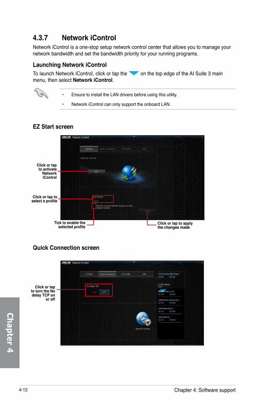
4-12 Chapter 4: Software support
Ch
apter 4
4.3.7 Network iControlNetwork iControl is a one-stop setup network control center that allows you to manage your network bandwidth and set the bandwidth priority for your running programs.
Launching Network iControlTo launch Network iControl, click or tap the on the top edge of the AI Suite 3 main menu, then select Network iControl.
• Ensure to install the LAN drivers before using this utility.
• Network iControl can only support the onboard LAN.
EZ Start screen
Click or tap to activate
Network iControl
Tick to enable the selected profile
Click or tap to select a profile
Click or tap to apply the changes made
Quick Connection screen
Click or tap to turn the No delay TCP on
or off

ASUS P9D WS 4-13
Ch
apte
r 4
EZ Profile screen
Tick to assign a schedule of your network programs to avoid network congestions
Click or tap to save the profile settings or rename the profile
Select a program from
this list and click to
add to your network profile
Click or tap to select a
network profile
Click or tap to set the
program as High, Normal,
or Low priority
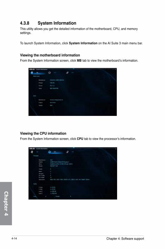
4-14 Chapter 4: Software support
Ch
apter 4
4.3.8 System InformationThis utility allows you get the detailed information of the motherboard, CPU, and memory settings.
To launch System Information, click System Information on the AI Suite 3 main menu bar.
Viewing the motherboard informationFrom the System Information screen, click MB tab to view the motherboard’s information.
Viewing the CPU informationFrom the System Information screen, click CPU tab to view the processor’s information.

ASUS P9D WS 4-15
Ch
apte
r 4
Viewing the SPD informationFrom the System Information screen, click SPD tab to view the memory’s information.

4-16 Chapter 4: Software support
Ch
apter 4
4.3.9 USB BIOS FlashbackUSB BIOS Flashback allows you to check and save the latest BIOS version to a USB storage device. Use this utility to quickly check for the latest available BIOS and set a schedule to when you can download for a newer version.
To launch USB BIOS Flashback, click USB BIOS Flashback on the AI Suite 3 main menu bar.
Scheduling the BIOS download1. In the Download Setting field, tick Schedule (days) then select the number of days for
the BIOS download schedule.
2. Click Apply to save the BIOS download schedule. Click Cancel to cancel the download schedule.
Downloading the updated BIOS
Before you start downloading, ensure that you have installed the USB storage device to your computer’s USB port that supports USB BIOS Flashback. Refer to section 2.3.1 Rear I/O connection of your user manual for more details.
To download the updated BIOS:
1. From the USB BIOS Flashback screen, click Check for New BIOS Update to check for the latest BIOS version.
Wait for the system to check the latest BIOS version.
2. After the utility detects a new BIOS, click from the Save to: field, select the USB flash drive, then click Download.
3. After the download is complete, click OK.
Current BIOS information
Set a schedule for the BIOS Update
download
Click to check for a new BIOS
update available for download
Click to cancel the download schedule setting
Click to apply the download schedule setting
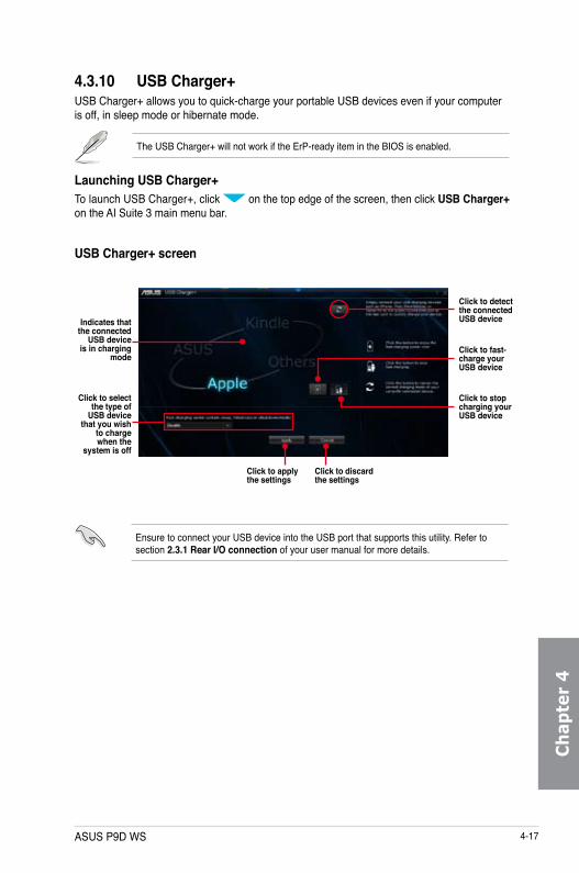
ASUS P9D WS 4-17
Ch
apte
r 4
4.3.10 USB Charger+USB Charger+ allows you to quick-charge your portable USB devices even if your computer is off, in sleep mode or hibernate mode.
The USB Charger+ will not work if the ErP-ready item in the BIOS is enabled.
Launching USB Charger+To launch USB Charger+, click on the top edge of the screen, then click USB Charger+ on the AI Suite 3 main menu bar.
USB Charger+ screen
Click to detect the connected USB device
Click to apply the settings
Click to discard the settings
Click to fast-charge your USB device
Indicates that the connected
USB device is in charging
mode
Click to stop charging your USB device
Click to select the type of
USB device that you wish
to charge when the
system is off
Ensure to connect your USB device into the USB port that supports this utility. Refer to section 2.3.1 Rear I/O connection of your user manual for more details.

4-18 Chapter 4: Software support
Ch
apter 4
4.3.11 Audio configurationsThe Realtek® audio CODEC provides 8-channel audio capability to deliver the ultimate audio experience on your computer. The software provides Jack-Sensing function, S/PDIF Out support, and interrupt capability. The CODEC also includes the Realtek® proprietary UAJ® (Universal Audio Jack) technology for all audio ports, eliminating cable connection errors, and giving users plug and play convenience.Follow the installation wizard to install the Realtek® Audio Driver from the support DVD that came with the motherboard package.If the Realtek® audio software is correctly installed, you will find the Realtek® HD Audio Manager icon on the taskbar. Double-click on the icon to display the Realtek® HD Audio Manager.
Realtek® HD Audio Manager
A. Realtek® HD Audio Manager with DTS UltraPC II for Windows® 8 / Windows® 7 / Windows® Vista
Configuration option tabs (vary with the audio devices connected) Advanced settings
Set default device button
Control settings panel
Analog and digital connector status
This version of Realtek HD Audio Manager supports Intel® 8 Series motherboards and other selected models.
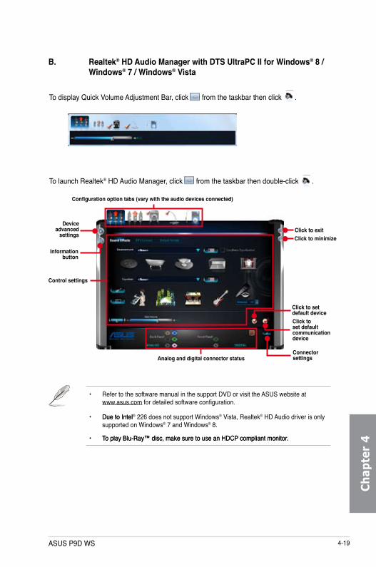
ASUS P9D WS 4-19
Ch
apte
r 4
• Refer to the software manual in the support DVD or visit the ASUS website at www.asus.com for detailed software configuration.
• Due to IntelDue to Intel® 226 does not support Windows® Vista, Realtek® HD Audio driver is only supported on Windows® 7 and Windows® 8.
• To play Blu-Ray™ disc, make sure to use an HDCP compliant monitor.To play Blu-Ray™ disc, make sure to use an HDCP compliant monitor.
B. Realtek® HD Audio Manager with DTS UltraPC II for Windows® 8 / Windows® 7 / Windows® Vista
Control settings
Configuration option tabs (vary with the audio devices connected)
Device advanced
settings
Information button
Connector settingsAnalog and digital connector status
Click to set default device
Click to exitClick to minimize
To launch Realtek® HD Audio Manager, click from the taskbar then double-click .
To display Quick Volume Adjustment Bar, click from the taskbar then click .
Click to set default communication device

4-20 Chapter 4: Software support
Ch
apter 4

ASUS P9D WS 5-1
Chapter 5Chapter 5: Multiple GPU technology support
5.1 ATI® CrossFireX™ technologyThe motherboard supports the ATI® CrossFireX™ technology that allows you to install multi-graphics processing units (GPU) graphics cards. Follow the installation procedures in this section.
5.1.1 Requirements
• In CrossFireX mode, you should have two identical CrossFireX-ready graphics cards or one CrossFireX-ready dual-GPU graphics card that are ATI® certified.
• Ensure that your graphics card driver supports the ATI CrossFireX technology. Download the latest driver from the AMD website (www.amd.com).
5.1.2 Before you beginFor ATI CrossFireX to work properly, you have to uninstall all existing graphics card drivers before installing ATI CrossFireX graphics cards to your system.
To uninstall existing graphics card drivers
1. Close all current applications.2. For Windows XP, go to Control Panel > Add/Remove Programs.
For Windows Vista, go to Control Panel > Programs and Features.3. Select your current graphics card driver/s. 4. For Windows XP, select Add/Remove.
For Windows Vista, select Uninstall.5. Turn off your computer.
• We recommend that you install additional chassis fans for better thermal environment.
• Visit the ATI Game website at http://game.amd.com for the latest certified graphics card and the supported 3D application list.

5-2 Chapter 5: Multiple GPU technology support
Ch
apter 5
5.1.3 Installing two CrossFireX™ graphics cards
The following pictures are for reference only. The graphics cards and the motherboard layout may vary with models, but the installation steps remain the same.
1. Prepare two CrossFireX-ready graphics cards.
2. Insert the two graphics card into the PCIEX16 slots. If your motherboard has more than two PCIEX16 slots, refer to Chapter 1 in this user manual for the locations of the PCIEX16 slots recommended for multi-graphics card installation.
3. Ensure that the cards are properly seated on the slots.
4. Align and firmly insert the CrossFireX bridge connector to the goldfingers on each graphics card. Ensure that the connector is firmly in place.
GoldfingersCrossFireX bridge (bundled with graphics cards)

ASUS P9D WS 5-3
Ch
apte
r 5
5. Connect two independent auxiliary power sources from the power supply to the two graphics cards separately.
6. Connect a VGA or a DVI cable to the graphics card.
5.1.4 Installing three CrossFireX™ graphics cards1. Prepare three CrossFireX-ready graphics cards.
2. Insert the three graphics card into the PCIEX16 slots. If your motherboard has more than three PCIEX16 slots, refer to Chapter 1 in this user manual for the locations of the PCIEX16 slots recommended for multi-graphics card installation.
3. Ensure that the cards are properly seated on the slots.
4. Align and firmly insert the two CrossFireX bridge connectors to the goldfingers on each graphics card. Ensure that the connectors are firmly in place.
5. Connect three independent auxiliary power sources from the power supply to the three graphics cards separately.
6. Connect a VGA or a DVI cable to the graphics card.

5-4 Chapter 5: Multiple GPU technology support
Ch
apter 5
5.1.5 Installing four CrossFireX™ graphics cards1. Prepare four CrossFireX-ready graphics cards.
2. Insert the four graphics card into the PCIEX16 slots. Refer to Chapter 1 in this user manual for the locations of the PCIEX16 slots recommended for multi-graphics card installation.
3. Ensure that the cards are properly seated on the slots.
4. Align and firmly insert the four CrossFireX bridge connectors to the goldfingers on each graphics card. Ensure that the connectors are firmly in place.
5. Connect four independent auxiliary power sources from the power supply to the four graphics cards separately.
6. Connect a VGA or a DVI cable to the graphics card.

ASUS P9D WS 5-5
Ch
apte
r 5
5.1.6 Installing the device driversRefer to the documentation that came with your graphics card package to install the device drivers.
Ensure that your PCI Express graphics card driver supports the AMD® CrossFireX™ technology. Download the latest driver from the AMD website (www.amd.com).
5.1.7 Enabling the AMD® CrossFireX™ technologyAfter installing your graphics cards and the device drivers, enable the CrossFireX™ feature through the AMD Catalyst™ Control Center in Windows environment.
Launching the AMD Catalyst Control CenterTo launch the AMD Catalyst Control Center:
1. Right-click on the Windows® desktop and select Catalyst Control Center.
2. Click Catalyst Control Center to configure the displays and settings of your AMD graphic cards.

5-6 Chapter 5: Multiple GPU technology support
Ch
apter 5
1
Enabling Dual CrossFireX technology1. In the Catalyst Control Center window, click Performance > AMD CrossFireXTM.
2. Select Enable CrossFireXTM.
3. Select a GPU combination from the drop-down list.
4. Click Apply to save and activate the GPU settings made.
2
3
4

ASUS contact information
ASUSTeK COMPUTER INC.Address 15 Li-Te Road, Peitou, Taipei, Taiwan 11259Telephone +886-2-2894-3447Fax +886-2-2890-7798E-mail [email protected] site tw.asus.com
Technical SupportTelephone +86-21-38429911Online support support.asus.com
ASUS COMPUTER INTERNATIONAL (America)Address 800 Corporate Way, Fremont, CA 94539, USATelephone +1-812-282-3777Fax +1-510-608-4555Web site usa.asus.com
Technical SupportTelephone +1-812-282-2787Support fax +1-812-284-0883Online support support.asus.com
ASUS COMPUTER GmbH (Germany and Austria)Address Harkort Str. 21-23, D-40880 Ratingen, GermanyFax +49-2102-959911Web site www.asus.deOnline contact www.asus.de/sales
Technical SupportTelephone +49-1805-010923*Support Fax +49-2102-9599-11Online support support.asus.com
* EUR 0.14/minute from a German fixed landline; EUR 0.42/minute from a mobile phone.

EC D
ecla
ratio
n of
Con
form
ity
We,
the
unde
rsig
ned,
M
anuf
actu
rer:
A
SU
STe
K C
OM
PU
TER
INC
. A
ddre
ss, C
ity:
4F, N
o. 1
50, L
I-TE
Rd.
, PE
ITO
U, T
AIP
EI 1
12, T
AIW
AN
C
ount
ry:
TAIW
AN
A
utho
rized
repr
esen
tativ
e in
Eur
ope:
A
SU
S C
OM
PU
TER
Gm
bH
Add
ress
, City
: H
AR
KO
RT
STR
. 21-
23, 4
0880
RA
TIN
GE
NC
ount
ry:
GE
RM
AN
Y
decl
are
the
follo
win
g ap
para
tus:
Pr
oduc
t nam
e :
Mot
herb
oard
Mod
el n
ame
: P9
D W
S
conf
orm
with
the
esse
ntia
l req
uire
men
ts o
f the
follo
win
g di
rect
ives
:
2004
/108
/EC
-EM
C D
irect
ive
EN
550
22:2
010
EN
610
00-3
-2:2
006+
A2:2
009
EN
550
13:2
001+
A1:2
003+
A2:
2006
EN
550
24:2
010
EN
610
00-3
-3:2
008
EN
550
20:2
007+
A11:
2011
1999
/5/E
C-R
&TT
E D
irect
ive
EN
300
328
V1.
7.1(
2006
-10)
E
N 3
00 4
40-1
V1.
6.1(
2010
-08)
E
N 3
00 4
40-2
V1.
4.1(
2010
-08)
E
N 3
01 5
11 V
9.0.
2(20
03-0
3)
EN
301
908
-1 V
5.2.
1(20
11-0
5)
EN
301
908
-2 V
5.2.
1(20
11-0
7)
EN
301
893
V1.
6.1(
2011
-11)
E
N 3
02 5
44-2
V1.
1.1(
2009
-01)
E
N 3
02 6
23 V
1.1.
1(20
09-0
1)
EN
503
60:2
001
EN
624
79:2
010
EN
503
85:2
002
EN
623
11:2
008
EN
301
489
-1 V
1.9.
2(20
11-0
9)
EN
301
489
-3 V
1.4.
1(20
02-0
8)
EN
301
489
-4 V
1.4.
1(20
09-0
5)
EN
301
489
-7 V
1.3.
1(20
05-1
1)
EN
301
489
-9 V
1.4.
1(20
07-1
1)
EN
301
489
-17
V2.1
.1(2
009-
05)
EN
301
489
-24
V1.5
.1(2
010-
09)
EN
302
326
-2 V
1.2.
2(20
07-0
6)
EN
302
326
-3 V
1.3.
1(20
07-0
9)
EN
301
357
-2 V
1.4.
1(20
08-1
1)
EN
302
291
-1 V
1.1.
1(20
05-0
7)
EN
302
291
-2 V
1.1.
1(20
05-0
7)
2006
/95/
EC-L
VD D
irect
ive
EN 6
0950
-1 /
A12:
2011
E
N 6
0065
:200
2 / A
12:2
011
2009
/125
/EC
-ErP
Dire
ctiv
e
Reg
ulat
ion
(EC
) No.
127
5/20
08
Reg
ulat
ion
(EC
) No.
642
/200
9
Reg
ulat
ion
(EC
) No.
278
/200
9
2011
/65/
EU-R
oHS
Dire
ctiv
e
V
er. 1
3020
8
CE
mar
king
Dec
lara
tion
Dat
e: 2
9/04
/201
3 Ye
ar to
beg
in a
ffixi
ng C
E m
arki
ng:2
013
Pos
ition
: C
EON
ame
: Je
rry
She
n
Sig
natu
re :
____
____
__
(EC
con
form
ity m
arki
ng)
DE
CL
AR
AT
ION
OF
CO
NFO
RM
ITY
Per F
CC
Par
t 2 S
ectio
n 2.
107
7(a)
R
espo
nsib
le P
arty
Nam
e:
Asu
s Com
pute
r In
tern
atio
nal
A
ddre
ss:
800
Cor
pora
te W
ay, F
rem
ont,
CA
945
39.
Ph
one/
Fax
No:
(5
10)7
39-3
777/
(510
)608
-455
5
here
by d
ecla
res t
hat t
he p
rodu
ct
Prod
uct N
ame
: Mot
herb
oard
Mod
el N
umbe
r : P
9D W
S
Con
form
s to
the
follo
win
g sp
ecifi
catio
ns:
FCC
Part
15, S
ubpa
rt B,
Uni
nten
tiona
l Rad
iato
rs
Supp
lem
enta
ry In
form
atio
n:
This
devi
ce c
ompl
ies
with
par
t 15
of th
e FC
C Ru
les.
Ope
ratio
n is
subj
ect t
o th
e fo
llow
ing
two
cond
ition
s: (1
) Th
is de
vice
may
not
cau
se h
arm
ful
inte
rfere
nce,
and
(2)
thi
s de
vice
mus
t ac
cept
any
int
erfe
renc
e re
ceiv
ed,
incl
udin
g in
terfe
renc
e th
at m
ay c
ause
und
esire
d op
erat
ion.
R
epre
sent
ativ
e Pe
rson
’s N
ame
:
Stev
e C
hang
/ Pr
esid
ent
Sign
atur
e :
D
ate
:
A
pr. 2
9, 2
013
Ver
. 120
601