Embed Size (px)
Citation preview

INSTALLATION ANDMAINTENANCE INSTRUCTIONS
EVC 13MOS GB 1538-2EVC 13511291
LEK2
1 bar 3
0 4
20 100
40 8060
°C
0 120


English
Removing the cover
General
System description4General4Principle of operation
Front panel5Heating curve offset5Select heating curve5Night reduction5Indicator lamps5Clock5Fuse5Switch5Switch6Boiler temperature6Boiler pressure
Settings7Heating control system7Default setting7Changing the room temperature8Basic values for the automatic heating control9Offset heating curve -29Offset heating curve 09Offset heating curve +29Setting after diagram
Clock10Setting of time10Programming of clock10Night reduction
Monitoring and maintenance11Max. thermostat11Tariff control, (option)11Safety valve12Pressure gauge12Temperature gauge12Operating fuse
Rectifying any malfunctions13Low room temperature
13No hot water13High room temperature14Emergency mode14Resetting the temperature limiter
Pipe installation15Transport and installation15Connections15Overflow pipe15Tapping valve15Circulation pump15Pump and pressure drop diagrams16Expansion vessel16Max radiator volume16Pressure controlled bypass valve16Draining the boiler water
Electrical installation17Connection17Cable entry17Switch18Returning power/self-test19Max thermostat/Temperature limitation
Commissioning and adjusting20Filling20Venting20Secondary adjustment
Electrical circuit diagram
Component positions26List of components
Dimensions27Dimensions and setting-out coordinates27Measuring principle
Accessories
28Fuse and tariff kit for electrical supply of external electricwater heater
28Room sensor
Enclosed kit
Technical specifications30Energy labelling
1EVC 13
Table of Contents

Removing the cover
LEK
LEK
LEK
LEK
1
2
EVC 132
English
Removing the cover

GeneralToget theultimatebenefit fromyour EVC13, you should read through these Installation andMaintenance Instructions.
EVC 13 is intended for houses with waterborne heating. The electric boiler must be installed horizontally, ideally ona cabinet type electric water heater, for example NIBE COMPACT.
The electric boiler is ready for centralised load control, has integrated load monitor and has accessory equipment fortariff control of the electric water heater, which can be directly supplied direct from the boiler. The controls are con-veniently located on the front panel and easy to see.
EVC 13 is a high quality electric boilerwith a long service life, developed andmade in Sweden for Swedish conditions.
Serial number* (103), must always be stated in all correspondence with NIBE.
089_ _ _ _ _ _ _ _ _ _ _
Installation date
Installer
Setting "Power limiting"
Setting "Fuse size" (load monitor)
Setting "Max thermostat"
Setting "Temperature limiting"
Setting "Heating curve selection"
Setting "Offset heating curve"
Insert any notes here.
Datum__________________________ Sign___________________________
This appliance can be used by children aged from 8 years and above and persons with reducedphysical, sensory or mental capabilities or lack of experience and knowledge if they have beengiven supervision or instruction concerning use of the appliance in a safe way and understandthe hazards involved. Children shall not play with the appliance. Cleaning and user maintenanceshall not be made by children without supervision.
Rights to make any design or technical modifications are reserved.
©NIBE 2015.
3EVC 13
English
General

System description
GeneralEVC 13 has outdoor temperature controlled boiler temper-ature, which is why a shunt valve is not needed. Outdoortemperature sensor supplied. The power is connected anddisconnected using two contactors and two relays.
EVC 13 has an integrated circulation pump, expansionvessel, safety valve, drain valve, load monitoring input forcentralised load control.
Current regulations require the heating installation to beinspected before it is commissioned. The inspection mustbe carried out by a suitably qualified person and shouldbe documented.
The above applies to electric boilers with a closed expan-sion vessel. If the boiler or the expansion vessel is replaced,the installation must be inspected again.
Principle of operation
ExplanationOutside sensorGT1Boiler/supply temperature sensorGT2Safety valve, boilerSÄVExpansion vesselEXPTapping valveAV1Shut-off valve, radiator circuit supply lineAV2*Shutoff valve in radiator circuit return lineAV3*Filler valveAV4Pressure controlled bypass valveAV7Circulation pumpCPImmersion heaterEPHeating control systemRCConnection clockURContactor tariff control of electric water heaterK2*Bypass of tariff controlBR*Miniature circuit-breaker groupSÄK*Radiator circuitRAD*
*Not included in standard delivery
RAD*P
GT1
SÄVGT2
CP
RC
Till
VV
B
EXP
AV1
AV3*
AV2*
EP
UR
Mat
ning
EVC 13
Från tariffur
K1
K2* BR*SÄK*
Utrustning för matning av yttre elvattenvärmare (tillbehör)
Vede
nläm
mitt
imee
n
Syö
ttö
Tariffikellosta
K1
Laite ulkoisen vedenlämmittimen syöttöä varten (lisävaruste)
AV7
AV4
RAD*P
GT1
SÄVGT2
CP
RC
EXP
AV1
AV3*
AV2*
EP
UR
AV5AV6
EVC 13
K2* BR*SÄK*
AV7
AV4
From Tariff clock
Equipment for supplying external electric water heater (accessory)
SupplyTo HWH
EVC 13
EVC 134
English
System description

Front panel
Day
15
12
24
21
618
R
3
9
15
ON O FF
2
1 bar 3
0 4
20 100
40 8060
°C
0 120
Indicator lamps
Night reduction
Boiler temperatureFuse
Switch
SwitchClock
Selection,heating curve
Offset,heating curve
Boiler pressure
Heating curve offsetThis setting knob is used to increase or decrease theheat, see section ・Changing the room temperat-ure" on page 7.
Select heating curveThe setting depends on the geographical situationand type of heating system. For correct setting, seesection ・Default setting" on page 7.
Night reductionThis setting knob is used to change the heating fora certain time of the day. The change is connectedin and out according to the times set on the clock,see also under "Switch"
Indicator lamps■ The top lamp lights when the immersion heater
is connected.■ The lower lamp is lit:■ When the electrical power is limited because
of overloaded main fuses.■ The first two hours after the boiler is started.■ During activated centralised load control if in-
stalled.■ Alternately flashing lamps mean that the outdoor
sensor is not correctly connected (short circuit oropen circuit).
ClockThe time for connecting and disconnecting of"Night reduction" is set on the clock, see also under"Switch"
FuseFuse (2.5 A) for control, and circulation pump.
SwitchThree position switch.
Always day
Night reduction inactive.
Automatic
Clock controlled night reduction.
Always night
Night reduction permanently active.
SwitchThe power switch has four positions:■ 0: The boiler is completely switched off.■ 1: Summer mode.
Only the clock and any tariff control for theheater are operational.
■ 2: Heating mode.
Normal operating mode, all functions connected.■ 3: Emergency mode.
This mode is used in the event of malfunctions.The boiler/supply temperature is then governedby the ”Max thermostat”. Circulation pump andimmersion heater are in operation.
The immersion heater is restricted to 6 kW. Anywater heater connected is powered up.
5EVC 13
English
Front panel

Boiler temperatureThe gauge displays the present boiler temperature,which is the same as the supply temperature.
Boiler pressureThe system/boiler pressure is shown here. Thegauge graduation is 0 – 4 bar. Normal pressure is0.5 – 1.5 bar.
EVC 136
English
Front panel

Settings
Heating control systemThe indoor temperature depends on several differentfactors. During the warmer times of the year, solar radi-ation and heat given off by people and equipment aresufficient to keep the house warm. When it gets colderoutside, the heating system must be started. The colderits gets, the hotter the radiators need to be.
Day
15
12
24
21
618
R
3
9
15
ON O FF
2
1 bar 3
0 4
20 100
40 8060
°C
0 120
Night reduction
Select heating curve
Heating curve offset
This adjustment is made automatically, however the correctbasic settings must first be made on the boiler (see below).
Default settingThe basic heating is set with the “Heating curve selection”knob and with the “Offset heating curve” knob. If you donot know the correct settings use the basic data from themap opposite. If the required room temperature is notobtained, post adjustment may be necessary
NOTEWait one day between settings so that the temperat-
ures have time to stabilise.
Post-balancing adjustment of the default setting.
Cold weather conditions
If the room temperature is too low, increase the “Heatingcurve selection” setting by one step clockwise.
If the room temperature is too high, reduce the “Heatingcurve selection” setting by one step anti-clockwise.
Warm weather conditions
If the room temperature is too low, increase the “Offsetheating curve” setting by one step clockwise.
If the room temperature is too high, reduce the “Offsetheating curve” setting by one step anti-clockwise.
Changing the room temperature
Changing the room temperature manually
If you want to temporarily or permanently lower or raisethe indoor temperature relative to the previously settemperature, turn the “Offset heating curve” knob anti-clockwise or clockwise. One line approximately representsa 1 degree change in room temperature.
Changing the room temperature with time controls
Use the "Night reduction" knob to increase or reduce theroom temperature at certain times of day. The start posi-tion for this knob is 0. A change of one corresponds toapproximately 1 degree change in room temperature. Thechange is active during the times that you have set on theclock (see section“Programming of clock" on page 10).
NOTEAn increase in the room temperature may be ”inhib-ited” by the radiator or under floor heating thermo-
stats, if so these must be turned up.
7EVC 13
English
Settings

Basic values for the automatic heating control
Skellefteå
Umeå
Örnsköldsvik
Sundsvall
Hudiksvall
Gävle
Stockholm
Visby
Luleå
JönköpingGöteborg
Borås
HalmstadMarkaryd
Helsingborg
Malmö
VäxjöKalmar
LinköpingNorrköping
Karlskrona
YstadSimrishamn
Örebro
Karlstad
Hässleholm
Uppsala
Västerås
Söderhamn
11 (5)
10 (5)
9 (5)
9 (4)
8 (4)
8 (4)
9 (4)
Gällivare
Östersund
Kiruna
Falun
9 (5)
11 (5)
12 (6)
Example
The values stated on the map apply for “Heating curve selection”.
The first value applies for low temperature radiator systems. Ifyou have a high temperature radiator system the stated valueshould increase by 3 units. In both cases the “Offset heatingcurve” is set to -2.
The value in brackets refers to under floor heating systems. Inthis case the “Offset heating curve” is set to -1.
The map values are usually a good starting point and concernan approximate room temperature of 20°C. The values can beadjusted later if necessary.
Examples of default values selection1. Houses with low temperature* radiator systems:
Markaryd = Area 10 (5). Set 10 on the ”Heating curve selec-tion” knob and -2 on the ”Offset heating curve” knob.
2. Houses with high temperature** radiator systems:
Markaryd = Area 10 (5). Set 10+3=13 on the "Heating curveselection" knob and -2 on the "Offset heating curve" knob.
3. House with under floor heating***.
Markaryd = Area 10 (5). Set 5 on the "Heating curve selection"knob and -1 on the "Offset heating curve" knob.
* A low temperature radiator system refers to a system where the supply temperature
needs to be 55 °C on the coldest day..
** A high temperature radiator system refers to a system where the supply temperature
needs to be 70 °C on the coldest day.
*** Under floor heating can be dimensioned very differently. Example 3 above refers
to a system where the supply temperature needs to be approximately 35–40 °C on
the coldest day.
EVC 138
English
Settings

Offset heating curve -2
30
40
50
60
80
• C
- 40 • C- 10010 - 20 - 30
15 14 13
11
10
9
8
7
6
5
4
3
2
1
- 5
+ 5
70
1617181912
Offset heating curveOutdoor temperature
Heating curveSupply temperature
Offset heating curve 0
30
40
50
60
80
• C
- 40 • C- 10010 - 20 - 30
15 14 13 12 11
10
9
8
7
6
5
4
3
2
1
- 5
+ 5
70
16171819
Offset heating curveOutdoor temperature
Heating curveSupply temperature
Offset heating curve +2
30
40
50
60
80
• C
- 40 • C- 10010 - 20 - 30
15 14 13 12 11 10
9
8
7
6
5
4
3
2
1
- 5
+ 5
70
16171819
Offset heating curveOutdoor temperature
Heating curveSupply temperature
Setting after diagramEVC 13 is equipped with an outdoor temperature con-trolled heating control system. This means the boilertemperature and therefore the supply temperature isregulated in relation to the current outdoor temperature.
The relationship between outdoor temperature and supplytemperature is set with the “Offset heating curve” and“Offset heating curve” knobs.
First, select "Offset heating curve". A suitable value forunder floor heating is -1 and for a radiator system -2.
The diagram is based on the dimensioned outdoor tem-perature for the area and the dimensioned supply temper-ature of the heating system. When these two values“meet”, the heating control's curve coefficient can be readoff.
Day
15
12
24
21
618
R
3
9
15
ON O FF
2
1 bar 3
0 4
20 100
40 8060
°C
0 120
Select heating curve
Heating curve offset
9EVC 13
English
Settings

Clock
Setting of time
NOTESetting is only necessary if automatic timing is re-
quired.
Resetting of clock
All programmed data in the clock can be erased by insert-ing a pin in the hole (R) and pushing. This is usually doneat start-up/commissioning.
Setting of time
Press the button. The ON/OFF indicator on the clock'sLCD display will go out. Hold the button in, to advancethe hours. Release the button at the required hour. Setthe minutes by short presses on the button.
Set weekdays by pressing the “Day” button until the re-quired weekday is set. Wait until the clock ON/OFF indic-ator relights, 5 seconds after the button was last pressed.When the correct time and day have been programmed,the clock can be programmed for function, see program-ming the clock.
Day
15
12
24
21
618
R
3
9
15
ON O FF
2
1 bar 3
0 4
20 100
40 8060
°C
0 120
On/Off indicationrelay status
Day/day buttonSettinghour/minute
Time activationblue - nightyellow - day
Time
Time activationfor activated
clock function
Reset/resetting
WeekdayMonday-Sunday
Manualoperation
15 minute key
Programming of clockThis programming is done to determine what times nightreduction is to be activated. The clock is programmed asfollows:■ Press the “Day” key until the day you want it shown in
the display.■ Program the desired time for night reduction by pressing
the buttons, which are placed around the clock display.The numbers around the display indicate the 24 hoursof the day.
One press: Night reduction activated the full hour.
Two presses: Night reduction activated in the first halfhour.
Three presses: Night reduction activated in the secondhalf hour.
Four presses: Night reduction deactivated the full hour.■ Select a new day with the “Day” key, and repeat the
previous procedure.■ When programming is completed press the ”Day” button
for the current day.
The clock can also be programmed in 15 minute intervals.Start by selecting the desired half hour where the 15minute activation is desired. Press the same segment but-ton again, and hold it in. By pressing the ”15” button inthis mode the desired 15 minute interval can be selected.The clock can also be operated manually (not normallyused). This is done as follows:■ Press the button, and keep it pressed in or 3 seconds.
The relay will switch off and OFF will start to flash.■ Press the button and the relay will shift between on
and off, ON/OFF will flash all the time.■ To return to automatic press the button again and
keep it pressed for 3 seconds. ON/OFF indication willnow light constantly.
Night reductionThis setting is used to change the heating during certainperiods during the day and night.
Night reduction is activated by the timer. The mode is se-lected using the switch (25).
The clock's programmed on/off determines the timeswhen the supply temperature should change to give achange of room temperature. ON indicates night reductionon. OFF indicates night reduction off.
If a reduction in the temperature is required, the value isreduced using the “Night reduction” knob. If an increasein the room temperature is required, the value is increasedusing the "Night reduction" knob. The setting range is -10to +10. One step change gives approx. 1 degree changein the room temperature.
NOTENOTE! An increase in the room temperature may beinhibited if the thermostats for the radiators or underfloor heating are set too low, if so these must be
turned up.
If you want to temporarily or permanently change theroom temperature the "night reduction" switch can beused in addition to the manual on/off on the clock. Thebutton switches between ”Constant day", Constant night”and ”Automatic” modes. See section "Front panel" on page5.
EVC 1310
English
Clock

Monitoring and maintenance
Max. thermostatTo access the max thermostat and the breaker for the tariffcontrol the front hatch must be opened. The max thermo-stat is set to limit the max boiler/supply line temperaturefor the heating system. Suitable setting is approx. 10 °Cabove the dimensioned supply temperature. This is espe-cially important for under floor heating, to prevent damageto the floor covering.
Tariff control, (option)With the switch pressed so that the red marking is visible,the external water heater is always powered via EVC 13regardless of external control.
Safety valveThe front hatch must be opened to access the safety valve.Turn the button anticlockwise and open the hatch.Manually open and close (turn the knob a click anticlock-wise) the safety valve approx. four times a year, at whichtime check that a small amount of water flows out andthat the valve seals closed. After the checks, ensure thatthe system has the required pressure. If necessary top upwith water. This is done using the hose via the drain valve(51) or via the filler valve fitted by the installer, see thesection ”“Commissioning and adjusting” – “Filling".
Effekt-begränsning
kW
Temperatur
begränsning
50°C
20 80
6040
7030
9711135
5 35
3010
252015
Säkrings-
storlek (A)
11EVC 13
English
Monitoring and maintenance

Pressure gaugeThe pressure gauge locatedon the right hand part of thefront panel should display apressure between the pre-pressure of the expansionvessel (normally 0.5 – 1.5 bar).
2
1 bar 3
0 4 If the pressure is too low, thereis a risk that not all the radiat-ors will heat up. If the pressureis too high, the safety valvemust release excess water. Thehighest pressure is obtainedwhen it is coldest outdoors.Water must be topped upwhen necessary, see the sec-tion ”Commissioning and ad-justing” – “Filling”.
Temperature gaugeThe temperature gauge loc-ated on the right hand part ofthe front panel displays thepresent boiler/supply temper-ature.
20 100
40 8060
°C
0 120
Operating fuseThe boiler's circulation pumpand operating circuits arefused by a 2.5A glass fuse. Thisis accessible from the front ofthe panel. If the fuse hastripped, the cause must be es-tablished and rectified beforethe fuse is replaced.
EVC 1312
English
Monitoring and maintenance

Rectifying any malfunctions
Low room temperature■ Circuit or main MCB tripped.■ Tripped operating fuse, see section ”Operating fuse" on
page 12.■ Incorrectly set heat curve, see section ”Default setting"
on page 7.■ Tripped temperature limiter, see section "Resetting the
temperature limiter" on page 14.■ Air in the boiler/heating system.■ Circulation pump stopped.■ Max thermostat, or temperature limit, set too low see
section ”Max. thermostat" on page 11and ”Max thermo-stat/Temperature limitation" on page 19.
■ The power switch set to position 1 or in position 0.■ Air in the circulation pump.■ Too low capacity set on the circulation pump.■ Switch (25) set in position "Constant night”.■ Radiator thermostats/room thermostat set too low.■ The load monitor restricts part of the power because
there is too great a total load on the main fuse.
No hot waterWhen EVC 13 feeds an electric water heater, a lack of hotwater can be caused by one of the following:■ Circuit or main MCB tripped.■ Water heater blocked by tariff control, where applicable.■ High hot water consumption (especially during tariff
control).■ Tripped internal fuse (27) (only in cases of internal on-
ward supply to electric water heater).
High room temperature■ Incorrectly set heat curve, see section ”Default setting"
on page 7.■ Radiator thermostats/room thermostat set too high.
NOTEThe product's serial number should always be stated
with all correspondence with NIBE.
089_ _ _ _ _ _ _ _ _ _ _
13EVC 13
English
Rectifying any malfunctions

Emergency modeEVC 13 is equipped with an ”Emergency mode” (position 3) onthe operating mode switch, as an additional safety measure. Thismode can be used if the normal automatic controls do not work.In this mode, the max thermostat controls the boiler/supplytemperature to the set value. Circulation pump and immersionheater in operation. The immersion heater is limited to 6 kW.
Any water heater is supplied with power.
Effekt-begränsning
kW
Temperatur
begränsning
50°C
20 80
6040
7030
9711135
5 35
3010
252015
Säkrings-
storlek (A)
Resetting the temperature limiterIf the temperature limiter has tripped, it is reset by pressingthe reset button, using a screwdriver or similar.
Effekt-begränsning
kW
Temperatur
begränsning
50°C
20 80
6040
7030
9711135
5 35
3010
252015
Säkrings-
storlek (A)
Reset button
NOTEIf the cause of themalfunction cannot be located andrectifiedusing theabove, a servicemust be requested.
EVC 1314
English
Rectifying any malfunctions
Pipe installation
Transport and installationThe electric boiler must be transported and stored dry.EVC 13 is designed to be positioned on top of an electricwater heater of the NIBE COMPACT type. Ensure that anyanode in the water heater is accessible. For installationand access for service, there must be space of approx.30 cm above and approx. 60 cm in front of the boiler.
NOTEEVC 13must be installed horizontally, at least 50 cmfrom the floor. To ensure sufficient ventilation for theelectric components, there must be an air gap of atleast 10 mm under the bottom plate of the boiler.
ConnectionsPipe installation must be carried out in accordance withcurrent norms and directives. The boiler is equipped withR20 connections, externally threaded. Shut off valvesshould be installed outside EVC 13 to simplify any futureservice.
NOTEThe pipe installation must be flushed, so that anycontaminants do not damage the equipment.
Overflow pipeThe overflow pipe must be routed according to currentnorms and directives.
The overflow pipe from the safety valves must be routedto a floor drain to prevent hot water splashes whenchecking the valves or when bleeding the boiler. The outletof the overflow pipe must be visible.
When installing a NIBE COMPACT water heater, the over-flow pipe for the electric boiler must be routed straightdown through the top panel of the water heater.
Tapping valveEVC 13 is equipped with a drain valve (51) on the boilerwith a R15 ( 1/2” ) hose connection. To drain the boiler,remove the cap for the valve and screw the hose connec-tion into position. Open the drain valve. The safety valve(52) is then set to the open position for air supply. Thedrain valve for the radiator system must be located in asuitable place.
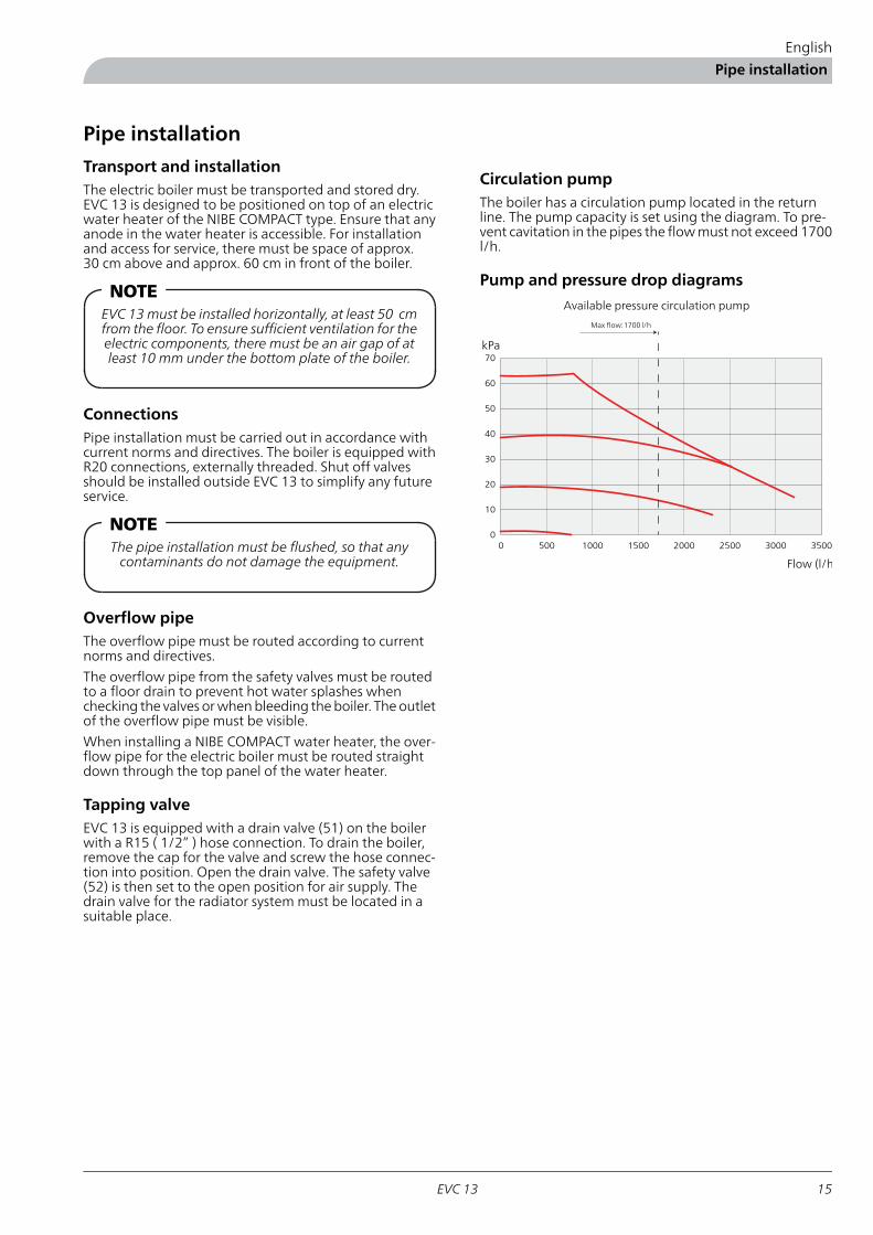
Circulation pumpThe boiler has a circulation pump located in the returnline. The pump capacity is set using the diagram. To pre-vent cavitation in the pipes the flow must not exceed 1700l/h.
Pump and pressure drop diagrams
00 500
Tillgängligt tryck (Pa)
3000 3500
Flöde (l/h)
2000 2500
10
20
30
1000 1500
40
50
60
70
Max flöde: 1700 l/h
Available pressure circulation pump
kPa
Flow (l/h
Max flow:1700 l/h
15EVC 13
English
Pipe installation

Expansion vesselThe expansion vessel (85) volume is 12 litres and has a pre-pres-sure of 50 kPa (0.5 bar) as standard. This means that the maxim-um height (H) between the vessel and the highest situated radi-ator is 5 m, see the figure to the side.
If the standard pre-pressure in the pressure vessel is not highenough it can be increased by adding air via the valve in the ex-pansion vessel. The pre-pressure of the expansion vessel mustbe stated in the inspection document. Any change in the pre-pressure affects the ability of the expansion vessel to handle theexpansion of the water.
If the heating installation has an open expansion vessel, the dis-tance between the highest radiator and the expansion vesselmust not be less than 2.5 m.
HM
in 2
,5 m
Max radiator volumeMax permitted radiator volume is 150 litres at a pre-pressure of0.5 bar.Pressure controlled bypass valveEVC 13 is equipped with a pressure controlled bypass valve (48).This is to protect the circulation pump in installations where theradiator flow can stop completely. When the radiator side isclosed the boiler water is circulated across the pump internallyin EVC 13.
Draining the boiler water
HUMMEL
Patent
! WARNING!Before draining the boiler water, cut the power sup-
ply.
The drain valve is used to drain the boiler of water. Un-screw the protective cap and install a hose on the drainingpipe, open the valve.
Arrange air supply, for example via the safety valve bysetting it to open mode.
EVC 1316
English
Pipe installation

Electrical installation
NOTEElectrical installation and service must be carried outunder the supervision of a qualified electrician. Elec-trical installation and wiring must be carried out in
accordance with the stipulations in force.
Connection■ If an insulation test is to be carried out in the building,
disconnect the boiler.■ If the building is equipped with an earth-fault breaker,
EVC 13 should be equipped with a separate one.■ Connect the boiler on terminal block (9) to 400 V 3-
phase, neutral + ground via an electrical distribution unitwith fuses.
■ EVC 13 does not include an omnipolar circuit breakeron the incoming power supply. The installation must bepreceded by a circuit breaker with at least a 3 mm gap.
■ Connection must not be carried out without the permis-sion of the electricity supplier and must occur under thesupervision of a qualified electrician.
Select max. output using the power limiter, see section ・Power control immersion heater" on page 18. The installermust document the selected output. The factory settingfor the power limit is 9.0 kW.
All electrical equipment, except for the outdoor sensorand current sensor, come already connected internally.Connecting outdoor temperature sensors is described insection "Outside sensor" on page 19
The boiler is equipped with load monitor, prepared forcentralised load control and has equipment for tariff con-trol of electric water heater as an option.
Cable entryCable entry is at the rear or top of the boiler, see section".Component positions" on page 25.
Switch■ Mode "0"
The boiler is completely switched off, heating not avail-able.
NOTETerminal block (26) is supplied with power.
■ Mode "1"
Only clock and any tariff control of water heaters run-ning.
■ Mode "2"
Normal operating mode. As mode”1” but with clock,immersion heater, automatic controls and circulationpump connected.
■ Mode "3"
Emergency mode. This mode can be used temporarily ifsomething in the automatic controls does not work. Theboiler/supply temperature is then governed by the maxthermostat. Pump and immersion heater (limited to 6kW) are in operation. Any connected water heater issupplied with power.
NOTECheck that the max thermostat is not set too high.This is particularly important if there is an under floor
heating system.
NOTEThepower switchmust not be turned from”0”beforethe boiler has been filled with water. Otherwise, thetemperature limiter, thermostat, thermometer and
the immersion heater could be damaged.
17EVC 13
English
Electrical installation

Returning power/self-testThe electric boiler is equipped with a time relay, whichblocks part of the immersion heater so that a maximumof 6.0 kW is connected the first two hours after the boilerhas been disconnected.
The time delay can be easily bypassed by pressing the quickstart button. This action can be used when servicing andfunction-testing the boiler.
NOTEHowever, there is always 4 minutes between eachstep size (see table under heading ”Power control
immersion heater().
EVC 13 has an integrated self-test program. This is activ-ated by holding the quick start button in, then pressingthe restart button. The quick start button is released whenthe relay engages. The self-test runs through the necessaryrelay combinations. After completed self-test the electricboiler must be restarted again.
GRUNDFOS
Type UPS 25 - 60 130 P/N:59526447
230-
50Hz
DK
PC:0202NIB
2,5uFIP 44
TF 110
Class H
Max 10bar
1/1(A) P1(W)
020 45
030 65
040 90
Restart buttonConcealed behind the relay board!
Quick start button (2 hour delay)Concealed behind the relay board!
Power control immersion heater
The boiler temperature is controlled by the outdoor tem-perature. The control equipment connects power in stepsof 1 – 2 kW and controls itself in the relevant power range.Restriction of the power is set using the ”Power restriction”potentiometer, see image. To maintain an even supplytemperature, the stepping is time limited to 3-4 minutesper power step.
Effekt-begränsning
kW
Temperatur
begränsning
50C
20 8a0
6040
7030
9711135
5 35
3010
252015
Säkrings-
storlek (A)
Effekt-begränsning
kW
Temperatur
begränsning
50°C
20 80
6040
7030
9711135
5 35
3010
252015
Säkrings-
storlek (A)
Effekt-begränsning
kW
Temperaturbegränsning
50C
20 80
6040
7030
9711135
5 35
3010
2 520
15Säkrings-storlek (A)
Load per phase (A)Step size (kW)Output (kW)
L3L2L1
-5.05.022
5.85.85.82+24
4.39.39.33+25
8.78.78.766
10.110.110.12+2+37
8.713.713.76+28
13.013.013.06+39
13.018.018.06+3+211
5.018.818.86+3+2+213
Centralised load control/load monitor
If centralised load control or load monitor is used the HPpipes for signal cables must be routed to the boiler. Theload monitor is set using the ”Fuse size" potentiometer,see section "Power control immersion heater" on page 18.Connection of the load monitor current sensor is made onthe terminal block (14) pre Safety Extra-Low Voltage (SELV),see image. Centralised load control is connected usingpotential free connections on the same terminal block.
29
121110987654321
14
50% 100%
29
121110987654321
14
50% 100%
Centralised loadClosed contactcauses cut in
power (accessory)
Outside sensor
Current sensor
EVC 1318
English
Electrical installation

Max thermostat/Temperature limitationIn normal operation, the boiler's supply temperature isrestricted by the ”Temperature limitation” potentiometer,see image in section”Power control immersion heater”.Normal setting is approx. 5 °C above the dimensionedsupply temperature. In addition to the setting for ”Temper-ature limitation” there is also a ”Max thermostat”, whichalso has the task of ensuring the limitation of the supplytemperature. Normal setting is approx. 10 °C above thedimensioned supply temperature. During operation in R-mode, the supply temperature can be adjusted using themax thermostat.
Effekt-begränsning
kW
Temperatur
begränsning
50°C
20 80
6040
7030
9711135
5 35
3010
252015
Säkrings-
storlek (A)
Max. thermostat
Temperature limiter
Temperature limiting
Outside sensor
29
15
121110987654321
14
The signal from the outdoor temperature sensor controlsthe control centre so that the correct boiler/supply tem-perature is obtained. The relationship between outdoortemperature and boiler/supply temperature is set withthe "Offset heating curve" and "Heating curve selection"knobs. The outdoor temperature sensor is normally locatedon the north or north west wall, well protected frommechanical effects. The sensor must measure the correctoutdoor temperature and must therefore not be affectedby the morning sun, for example. Electrical connection ismade to the relay card (29) terminal block (14). If a conduitis used it must be sealed to prevent condensation in thesensor capsule. The minimum cable cross section shouldbe 0.4 mm2 up to 50 metres, for example, EKKX or LiYY.
Temperature limiter
The temperature limiter (6) cuts off the power supplybetween 90 – 100 °C and can be manually reset by pressingthe reset button, see section ”Resetting the temperaturelimiter" on page 14.
Boiler/Supply temperature sensor
Boiler/Supply temperature sensor (18), see section "Com-ponent positions" on page 25, measures the supply tem-perature and sends a signal to the automatic heatingcontrols, which in turn corrects the supply temperatureusing the immersion heater.
Temperature sensor data
Voltage (V)Resistance (kΩ)Temperature (°C)
4.78102.35-40
4.7073.51-35
4.6053.44-30
4.4739.29-25
4.3129.20-20
4.1221.93-15
3.9016.62-10
3.6512.71-5
3.389.810
3.097.625
2.805.9710
2.504.7115
2.223.7520
1.953.0025
1.702.4230
1.471.9635
1.271.6040
1.091.3145
0.941.0850
0.700.74660
0.510.52570
19EVC 13
English
Electrical installation
Commissioning and adjusting
2
1 bar 3
0 4
Effekt-begränsning
kW
Temperatur
begränsning
50°C
20 80
6040
7030
9711135
5 35
3010
252015
Säkrings-
storlek (A)
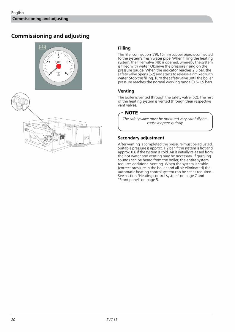
FillingThe filler connection (79), 15 mm copper pipe, is connectedto the system's fresh water pipe. When filling the heatingsystem, the filler valve (49) is opened, whereby the systemis filled with water. Observe the pressure rising on thepressure gauge. When the indicator reaches 2.5 bar, thesafety valve opens (52) and starts to release air mixed withwater. Stop the filling. Turn the safety valve until the boilerpressure reaches the normal working range (0.5-1.5 bar).
VentingThe boiler is vented through the safety valve (52). The restof the heating system is vented through their respectivevent valves.
NOTEThe safety valve must be operated very carefully be-
cause it opens quickly.
Secondary adjustmentAfter venting is completed the pressure must be adjusted.Suitable pressure is approx. 1.2 bar if the system is hot andapprox. 0.6 if the system is cold. Air is initially released fromthe hot water and venting may be necessary. If gurglingsounds can be heard from the boiler, the entire systemrequires additional venting. When the system is stable(correct pressure in the boiler and all air eliminated) theautomatic heating control system can be set as required.See section "Heating control system" on page 7 and“Front panel" on page 5.
EVC 1320
English
Commissioning and adjusting

Electrical circuit diagram
NOTETerminal block (26) is suppliedwithpower evenwhen
the power switch is in 0 position.
21EVC 13
English
Electrical circuit diagram

EVC 1322
English
Electrical circuit diagram

23EVC 13
English
Electrical circuit diagram

EVC 1324
English
Electrical circuit diagram

Component positions
LEK
5
01
xam
0
5+5-
Effekt-begränsning
kW
Temperatur
begränsning
50°C
20 80
6040
7030
9711135
5 35
3010
252015
Säkrings-
storlek (A)
7685 75312027 26 77 7843
9 1 8 13671042 640
22103
86
71
52 16 51 80 19 256 12 34 14 29
70
48
49
79
25EVC 13
English
Component positions

List of componentsImmersion heater 13 kW1Combined max thermostat and temperature limiter6Fuse, pump, automatic heat controls, 2.5 A7Power switch, positions 0 – 1 – 2 – 38Terminal block, power supply9Contactor, immersion heater control10Clock, for ”Clock function”12Terminal block, neutral and tariff control of externalwater heater
13
Terminal block, safety extra low voltage (SELV)14Outside sensor15Circulation pump16Boiler temperature sensor18Switch, tariff control of external water heater (access-ory)
19
Neutral terminal block (accessory)20
Current sensor21Load relief (accessory)22Switch, ”Constant day” – ”Automatic”– ”Constantnight reduction”
25
Terminal block for power supply to external waterheater
26
Fuse kit (accessory)27Relay card29Contactor (accessory)31Microprocessor card34Temperature gauge, boiler water40Pressure gauge, boiler water42Vent nipple, expansion vessel43Bypass valve48Filler valve49Draining valve*51Safety valve, boiler water 2.5 bar52Contactor, immersion heater control67
R 20 ext.Supply line, radiator water70R 20 ext.Return line, radiator water71
Lead in hole for supply cable to external water heater75HP pipe 16 mmElectrical inlet, safety extra low voltage (SELV)76HP pipe 16 mmElectrical inlet, tariff control77HP pipe 25 mmElectrical inlet, supply78Ø 15 mmFiller connection79R 15 ext.Drain connection, boiler water*80
Pressure expansion vessel; 12 litre, pre-pressure 50 kPa (0.5 bar)85Compression ring 22 mmConnection overflow pipe safety valve boiler water86
Serial number plate103
*Not visible in the image
EVC 1326
English
Component positions

Dimensions
Dimensions and setting-out coordinates
23
5
17
5
27
27
26
0
40
60
ca
30
0 *
Min
50
0
10
61
5
600
ca
60
0 *
Free space for air column
Safety Extra-Low Voltage (SELV)
Supply, electric boiler
Tariff control, hwh
Floor
* Free space for inspection and any service.
Measuring principle
Klämring
Klemmring
Compression ring
27EVC 13
English
Dimensions
Accessories
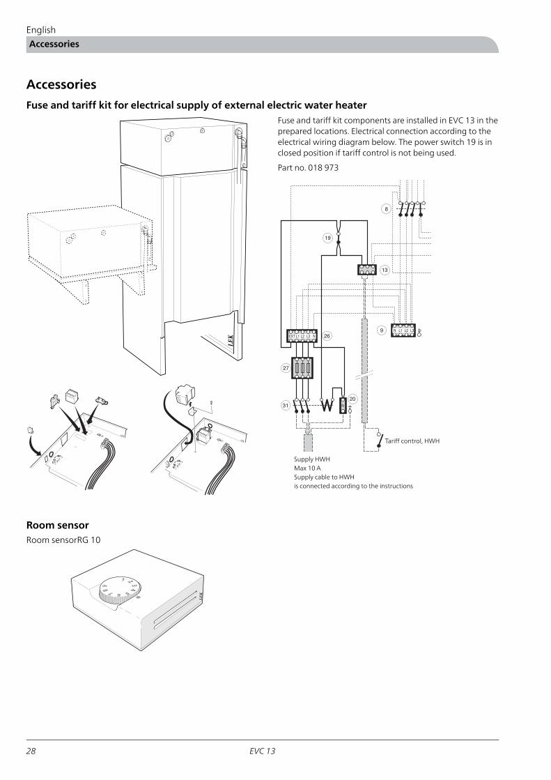
Fuse and tariff kit for electrical supply of external electric water heaterFuse and tariff kit components are installed in EVC 13 in theprepared locations. Electrical connection according to theelectrical wiring diagram below. The power switch 19 is inclosed position if tariff control is not being used.
LE
K
Part no. 018 973
9
20
13
31
19
8
N L1 L2 L3
N
NL1 L2 L3EXT
27
26
Supply HWHMax 10 ASupply cable to HWHis connected according to the instructions
Tariff control, HWHLEK
LEK
Room sensorRoom sensorRG 10
LE
K
EVC 1328
English
Accessories

Enclosed kit
LEK
NIBE AB
Utetemperatur givare
Outdoor temperature sensor
Aussentemperatur fühler
Artikel 018764
Outside sensor
Part no. 018 764
LE
K
LE
K
LE
K
Current sensors 3 x
Part no. 018 569
29EVC 13
English
Enclosed kit

Technical specifications
IP 21
EVC 13
260mmHeight600mmWidth615mmDepth36kgWeight5.5litreVolume
400 V 3N~50 HzVSupply voltage13kWMax output, electric heater
3-45WRated output, circulation pump21Enclosure class
0.3/3.0MPa/barMax permitted pressure0.25/2.5MPa/barCut-off pressure
30-85°CSetting max thermostat12litreExpansion vessel volume
Energy labelling
Information sheet
NIBESupplier
EVC 13Model
DEnergy efficiency class for space heating
9kWRated heat output (Pdesignh)20,310kWhAnnual energy consumption space heating
36.6%Seasonal space heating energy efficiency35dBSound power level LWA indoors
Data for energy efficiency of the package
EVC 13Model
IIController, class2%Controller, contribution to efficiency
38.6%Seasonal space heating energy efficiency of the pack-age
DSpace heating efficiency class of the package
The reported efficiency of the package also takes the controller into account. If an external supplementary boiler or solar heating is added to thepackage, the overall efficiency of the package should be recalculated.
EVC 1330
English
Technical specifications

Technical documentation
EVC 13Model
Yes NoCondensing boiler
Yes NoLow-temperature boiler
Yes NoB11 boiler
Yes NoCogeneration space heater
Yes NoCombination heater
%36.6ƞsSeasonal space heating energy efficiencykW9PratedRated heat output
For boiler space heaters and boiler combination heaters: Useful efficiencyFor boiler space heaters and boiler combination heaters: Useful heat output
%40ƞ4At rated heat output and high-temperature re-gime
kW9P4At rated heat output and high-temperature re-gime
%ƞ1At 30 % of rated heat output and low-temperat-ure regime
kWP1At 30 % of rated heat output and low-temperat-ure regime
Other itemsAuxiliary electricity consumption
kW0.15PstbyStandby heat losskWelmaxAt full load
kWPignIgnition burner power consumptionkWelminAt part load
kWh20,310QHEAnnual energy consumptionkW0.01PSBStandby mode
dB35LWASound power level, indoors
For combination heaters
%ƞwhWater heating energy efficiencyDeclared load profile for water heating
kWhQfuelDaily fuel consumptionkWhQelecDaily energy consumption
GJAFCAnnual fuel consumptionkWhAECAnnual energy consumption
31EVC 13
English
Technical specifications


WS name: -GemensamtWS version: a80 (working edition)Publish date: 2015-09-14 09:53
511291
PL
NL
FI
DK
DE
CZ
NIBE Energy Systems OY, Juurakkotie 3, 01510 Vantaa
3C Broom Business Park, Bridge Way, Chesterfield S41 9QG
Puh: 09-274 697 0 Fax: 09-274 697 40 E-mail: [email protected] www.nibe.fi
FRNIBE Energy Systems France Sarl, Zone industrielle RD 28 , Rue du Pou du Ciel - 01600 Reyrieux
Tél: 04 74 00 92 92 Fax: 04 74 00 42 00 E-mail: [email protected] www.nibe.fr
NIBE-BIAWAR Sp. z o. o. Aleja Jana Pawła II 57, 15-703 BIAŁYSTOK
Tel: 085 662 84 90 Fax: 085 662 84 14 E-mail: [email protected] www.biawar.com.pl
RU© "EVAN" 17, per. Boynovskiy, Nizhny Novgorod
Tel./fax +7 831 419 57 06 E-mail: [email protected] www.nibe-evan.ru
NIBE Energietechniek B.V., Postbus 634, NL 4900 AP Oosterhout
Tel: 0168 477722 Fax: 0168 476998 E-mail: [email protected] www.nibenl.nl
Vølund Varmeteknik A/S, Brogårdsvej 7, 6920 Videbæk
Tel: 97 17 20 33 Fax: 97 17 29 33 E-mail: [email protected] www.volundvt.dk
NIBE Systemtechnik GmbH, Am Reiherpfahl 3, 29223 Celle
Tel: 05141/7546-0 Fax: 05141/7546-99 E-mail: [email protected] www.nibe.de
CHNIBE Wärmetechnik AG, Winterthurerstrasse 710, CH-8247 Flurlingen
Tel: (52) 647 00 30 Fax: (52) 647 00 31 E-mail: [email protected] www.nibe.ch
ATKNV Energietechnik GmbH, Gahberggasse 11, 4861 Schörfling
Tel: +43 (0)7662 8963-0 Fax: +43 (0)7662 8963-44 E-mail: [email protected] www.knv.at
NIBE AB Sweden, Box 14, Hannabadsvägen 5, SE-285 21 Markaryd
Tel: +46-(0)433-73 000 Fax: +46-(0)433-73 190 E-mail: [email protected] www.nibe.eu
GBNIBE Energy Systems Ltd,
Tel: 0845 095 1200 Fax: 0845 095 1201 E-mail: [email protected] www.nibe.co.uk
NOABK AS , Brobekkveien 80, 0582 Oslo, Postadresse: Postboks 64 Vollebekk, 0516 Oslo
Tel. sentralbord: +47 23 17 05 20 E-mail: [email protected] www.nibeenergysystems.no
Druzstevni zavody Drazice s.r.o, Drazice 69, CZ - 294 71 Benatky nad Jizerou
Tel: +420 326 373 801 Fax: +420 326 373 803 E-mail: [email protected] www.nibe.cz