Embed Size (px)
Citation preview
Morphology, structure, and properties of metal oxide/polymernanocomposite electrospun mats
Natalia Hoogesteijn von Reitzenstein,1 Xiangyu Bi,1 Yu Yang,1 Kiril Hristovski,2 Paul Westerhoff1
1School of Sustainable Engineering and the Built Environment, Arizona State University, Tempe, Arizona 85287-30052The Polytechnic School, Arizona State University, Tempe, Arizona 85287-3005Correspondence to: N. H. von Reitzenstein (E - mail: [email protected])
ABSTRACT: Adding nanoparticles into polymer solutions before electrospinning creates unique hierarchical morphologies dispersed
throughout small diameter nanoparticle-polymeric fibers. Effects of polymer composition, nanoparticle (NP) type, loading, and elec-
trospinning voltage conditions were studied. As examples, indium, iron, and titanium oxide engineered nanoparticles (NPs) were dis-
persed into polyvinylpyrrolidone or polystyrene and electrospun. NP loadings below 5 wt % did not affect critical voltage required
for Taylor cone formation, whereas higher NP loadings require higher critical voltages. Polymeric fiber thickness and macroscopic
morphology is not impacted by up to 5 wt % NP loadings, and NP dispersion throughout the fibers were similar to their dispersion
in initial polymer suspension. NP loadings above 5 wt % increased viscosity, which decrease subsequent fiber diameter. Experiments
in water containing inorganic and organic pollutants in water demonstrate that the polymer is largely nonporous. This work enables
design of multifunctional nanomaterial-polymer composite fibers for wide-ranging applications such as water and air treatment.
VC 2016 Wiley Periodicals, Inc. J. Appl. Polym. Sci. 2016, 133, 43811.
KEYWORDS: electrospinning; fibers; nanocrystals; nanoparticles; nanowires
Received 5 January 2016; accepted 15 April 2016DOI: 10.1002/app.43811
INTRODUCTION
Electrospun polymer fibers with diameters in the submicron to
nanometer range have unique characteristics that led to increasing
interest in their applications as reinforcements for composite
materials, air or water filtration, soft tissue prostheses, wound
dressing, cosmetics, protective clothing, and sensors.1,2 Electro-
spinning uses an electrically charged jet of polymer solution to
produce polymer filaments by applying a high voltage potential
between 10–40 kV and a grounded collector. The surface tension
on the fluid droplet at the syringe tip is overcome by the strength
of the electric field and a charged jet of fluid stretches from the
syringe tip and deposits onto the grounded collector, forming a
mat of fibers with diameters in the micrometer and nanometer
scales. Nanoparticle (NP) addition into polymers produces nano-
composites known to improve mechanical strength, resistance to
wear, and thermal stability.3 Additionally, NP-polymer electro-
spun fiber composites also enhance the fiber performance due to
the multifunctionality of NPs as biocides, sorbents, and photoca-
talysts. As NP-polymer composites are being synthesized, limited
information across multiple NP types exists regarding impacts of
NPs on polymer spinning behavior.
Synergistic effects of physical parameters dictate the structure
and morphology of electrospun fibers.4 The electrospinning
process is a balance of parameters including, but not limited to,
conditions such as relative humidity, polymer weight, distance
between capillary tip and collector plate, feed rate of solution,
and solution composition.5–7 For example, adjusting the relative
humidity in the environment affects the number, diameter,
shape, and distribution of pores on the surface of electrospun
fibers.5 Electrostatically, there is a balance between the induced
charge on the polymer surface and the surface tension of that
polymer. Surface tension is overcome by applying voltage. Vis-
cosity dictates whether the polymer jet will break into droplets
or travel as a continuous stream to the collector plate. High vis-
cosity liquids will become jets, while low viscosity liquids will
break up.4 By altering physical parameters and manipulating
electrostatic forces, the fibers produced by electrospinning can
have a variety of morphologies suited to different purposes. For
example, fiber diameter may be manipulated via solution viscos-
ity and applied voltage. Depending on the final use of electro-
spun fiber mats (i.e., nonwoven textiles), controlling fiber
diameter can be controlled. In this work, fiber diameter is
shown to vary as an effect of NP addition. The addition of NP
Additional Supporting Information may be found in the online version of this article.
VC 2016 Wiley Periodicals, Inc.
WWW.MATERIALSVIEWS.COM J. APPL. POLYM. SCI. 2016, DOI: 10.1002/APP.4381143811 (1 of 9)
into solution adds another dimension to the process and its
product. There are few examples in the literature of the effect of
NP addition to polymer solutions prior to spinning and few
investigations of the effect of NP on electrospinning process
parameters.8,9 The effect of NP content on the formation of a
Taylor cone in polymer solutions for electrospinning presents a
gap in the literature that is important for future investigations
of electrospun fibers using NPs for functionalization.
Interest exists in coupling the benefits of metal oxide nanopar-
ticles with the process of electrospinning, affording several appli-
cations of economically produced, micrometer and nanometer-
scale fibers.10 For example, adding antimicrobial silver NP to a
mat of electrospun fibers grafted onto a membrane could help
prevent bacterial membrane fouling.11 Electrospinning polymeric
fibers for water treatment applications requires use of nonwater
soluble polymers, and hence dissolution in nonaqueous solvents is
required. Titanium dioxide (TiO2) is an inexpensive and effective
photocatalyst and chemical sensor in environmental remediation,
photovoltaics, and optics, and applications for electrospun fibers
made with TiO2 are beginning to be explored.12–15 Research on
interactions of individual metal oxide nanoparticles with poly-
mers during electrospinning have begun. For example, varying
weight percentages of TiO2 in a polyaniline solution affected
nanocomposite fiber diameter, while operating parameters such
as TiO2 loading content, humidity, and temperature affected the
physical properties, such as strength and brittleness, of electro-
spun polyacrylonitrile (PAN)-TiO2 fibers.8,9 Less has been
reported about the systematic influence of NP addition to poly-
mer solutions on electrospinning parameters (e.g., solution vis-
cosity) and resulting critical voltage or implications for fiber
morphology.
This study investigated hybridizing electrospun fibers with NP
and evaluated how the NP addition influenced polymer proper-
ties, electrospinning conditions, and electrospun fiber morphol-
ogy. Specifically, we quantified the differences in critical voltage
needed to produce an unstable and stable Taylor cone by loading
two polymer solutions with different NP weight percentages. Volt-
age was slowly increased until a stable Taylor cone was observed.
Nanoparticle-polymer composite solution viscosity was tested
using rheometry. Metal oxide nanoparticles (TiO2, indium oxide
(In2O3), hematite (Fe2O3) and electrospun polymeric fibers where
characterized using transmission electron microscopy (TEM) and
energy dispersive X-ray analysis (EDX). TiO2 was chosen because
of its widespread use as a photocatalyst and arsenic absorbent,
while In2O3 was chosen due to its use in semiconductor industries
plus its visual color observation ability and high sensitivity of
morphology using scanning electron microscopy (SEM) in order
to observe NP distribution in the fibers. Fe2O3 was chosen because
it is a good adsorbent of inorganic pollutants (such as arsenic) in
drinking water. The results are intended to aid in optimization of
electrospinning nanocomposites by showing how adding different
NP mass fractions can affect viscosity, voltage, surface morphol-
ogy, and diameter of fibers.
EXPERIMENTAL
Materials
Two polymers (Polyvinylpyrrolidone [PVP] K90 (MW 360,000 g/mol,
Fluka Analytical) and Polystyrene (PS, MW 350,000 g/mol, Aldrich
Chemistry) were used for electrospinning. These polymers were
chosen based on their high molecular weights suitable for electrospin-
ning. N,n-dimethylformamide (DMF, Sigma-Aldrich) was used as the
organic solvent to dissolve both of the polymers.
Nanoparticles used for loading include indium oxide nanopowder
from U.S. Research Nanomaterials, Inc. (Houston, TX) and
Degussa AG Aeroxide P25 TiO2 (Frankfurt am Main, Germany).
Fe2O3 NPs were synthesized by modifying a previously published
method.16 Briefly, anhydrous ferric acid (Sigma-Aldrich) was pre-
pared over heat in a 4 mM HCl solution and 0.25 M FeCl3 stock.
The solution was then placed in a laboratory oven (HP 5890 series
II) at 100 8C and incubated for 10 h. The Fe2O3 NPs were centri-
fuged and washed five times with nanopure water. After rinsing,
the Fe2O3 NPs were stored at 4 8C.
In2O3-polymer composite, TiO2-polymer composite, and Fe2O3-
polymer composite solutions were prepared by dispersing various
NP concentrations (0, 0.05, 0.5, and 5 wt %) in DMF by 1 h of
bath sonication (Branson 2510, Branson Ultrasonic, Dansbury,
CT). NP weight percentage loadings (0.05–5 wt %) into the poly-
mers were chosen to span multiple orders of magnitude. Polymer
(20 wt % of either PS or PVP) was added to the solution and
gently stirred for 24 h at 40 8C.
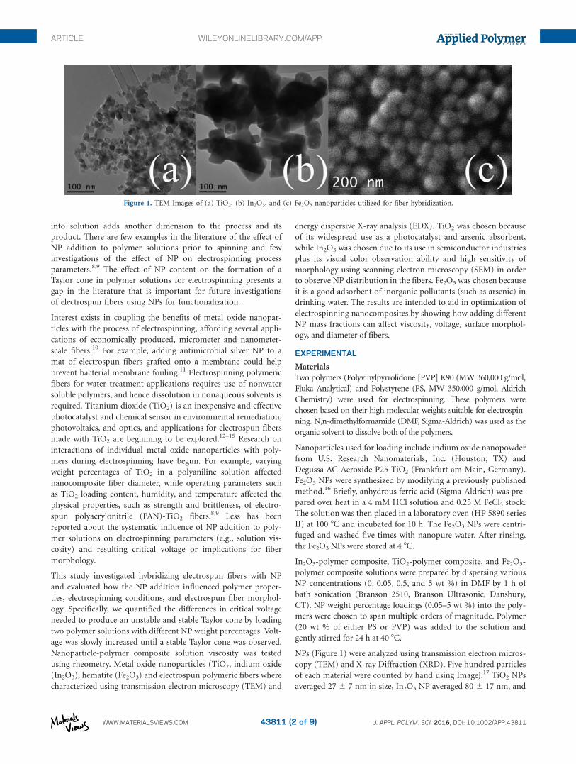
NPs (Figure 1) were analyzed using transmission electron micros-
copy (TEM) and X-ray Diffraction (XRD). Five hundred particles
of each material were counted by hand using ImageJ.17 TiO2 NPs
averaged 27 6 7 nm in size, In2O3 NP averaged 80 6 17 nm, and
Figure 1. TEM Images of (a) TiO2, (b) In2O3, and (c) Fe2O3 nanoparticles utilized for fiber hybridization.
ARTICLE WILEYONLINELIBRARY.COM/APP
WWW.MATERIALSVIEWS.COM J. APPL. POLYM. SCI. 2016, DOI: 10.1002/APP.4381143811 (2 of 9)
Fe2O3 averaged 46 6 3 nm. The XRD reflections of In2O3 NPs are
characteristic of phase-pure nanocuboids. TiO2 was mostly ana-
tase. Fe2O3 crystalline phase identification was confirmed by com-
paring XRD reflections with the pattern of the Joint Committee
on Powder diffraction Standards database (see supporting infor-
mation S1–S3).
Electrospinning
An apparatus similar to previously published electrospinning
systems was constructed.5,18–21 Briefly, electrospinning was per-
formed using a high voltage power supply that provided up to
40 kV (Gamma High Voltage, Ormond Beach, FL), a syringe
pump (New Era NE-300, Farmingdale, NY), a 10 mL plastic
syringe, and a grounded aluminum foil coated collector that
was placed 15 cm away from the syringe tip. The experimental
procedure involved loading the solution into a plastic 10 mL
syringe fitted with a stainless steel needle that was connected to
the high voltage power supply. The NP-polymer composite solu-
tion was injected at 20 mL/h through a stainless steel, 22-gauge
needle (Sigma-Aldrich stainless steel 304 syringe needle) with
an alligator clip attached to charge the needle and the polymer
solution as it exited the capillary tip. The entire system was
enclosed to mitigate the effects of air currents on the system
and for safety. Humidity was measured using a Xikar hygrome-
ter and was maintained at 40% at 75 8F using a sponge satu-
rated with deionized water inside the electrospinning enclosure.
All experiments were run grouped by metal oxide on the same
day in quick succession to maintain similar ambient experimen-
tal conditions.
Analytical Methods
Nanoparticles were characterized using a Philips CM200-FEG
transmission electron microscope and a Siemens D5000 powder
X-ray diffractometer. SEM images of fibers were obtained using
a JEOL 2010F. Viscosity of polymer solutions was measured
using a TA Instruments AR-G2 rheometer. Fiber diameters were
measured using ImageJ software (National Institutes of Health,
Washington, D.C.).
RESULTS AND DISCUSSION
Effect of Nanoparticle Doping on Critical Voltages to Produce
Taylor Cones
Taylor cone formation is an important feature of the electro-
spinning process because it indicates that the voltage applied
affects the surface tension of the solution, and because it is a
precursor to a stable, continuous polymer jet. The charged jet is
the distinguishing characteristic between electrospinning and
electrospraying, where the end result of electrospraying is
charged polymer droplets without fiber formation. The critical
voltage occurs when the jet forms. Droplet shape at the tip
varies with applied voltage. At lower voltages, the originating
drop at the capillary tip is larger than the diameter of the capil-
lary tip. As voltage increases, the jet originates first from the
bottom of the drop, and then the drop diameter decreases with
increasing voltage until the jet emerges from the solution within
the syringe tip.4 Little is known about the dependence of these
voltages on NP loadings in polymers.
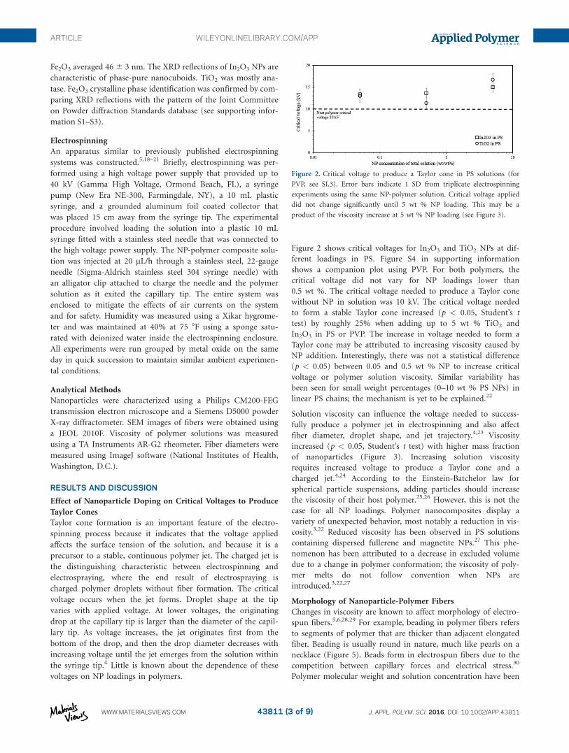
Figure 2 shows critical voltages for In2O3 and TiO2 NPs at dif-
ferent loadings in PS. Figure S4 in supporting information
shows a companion plot using PVP. For both polymers, the
critical voltage did not vary for NP loadings lower than
0.5 wt %. The critical voltage needed to produce a Taylor cone
without NP in solution was 10 kV. The critical voltage needed
to form a stable Taylor cone increased (p < 0.05, Student’s t
test) by roughly 25% when adding up to 5 wt % TiO2 and
In2O3 in PS or PVP. The increase in voltage needed to form a
Taylor cone may be attributed to increasing viscosity caused by
NP addition. Interestingly, there was not a statistical difference
(p < 0.05) between 0.05 and 0.5 wt % NP to increase critical
voltage or polymer solution viscosity. Similar variability has
been seen for small weight percentages (0–10 wt % PS NPs) in
linear PS chains; the mechanism is yet to be explained.22
Solution viscosity can influence the voltage needed to success-
fully produce a polymer jet in electrospinning and also affect
fiber diameter, droplet shape, and jet trajectory.4,23 Viscosity
increased (p < 0.05, Student’s t test) with higher mass fraction
of nanoparticles (Figure 3). Increasing solution viscosity
requires increased voltage to produce a Taylor cone and a
charged jet.4,24 According to the Einstein-Batchelor law for
spherical particle suspensions, adding particles should increase
the viscosity of their host polymer.25,26 However, this is not the
case for all NP loadings. Polymer nanocomposites display a
variety of unexpected behavior, most notably a reduction in vis-
cosity.3,22 Reduced viscosity has been observed in PS solutions
containing dispersed fullerene and magnetite NPs.27 This phe-
nomenon has been attributed to a decrease in excluded volume
due to a change in polymer conformation; the viscosity of poly-
mer melts do not follow convention when NPs are
introduced.3,22,27
Morphology of Nanoparticle-Polymer Fibers
Changes in viscosity are known to affect morphology of electro-
spun fibers.5,6,28,29 For example, beading in polymer fibers refers
to segments of polymer that are thicker than adjacent elongated
fiber. Beading is usually round in nature, much like pearls on a
necklace (Figure 5). Beads form in electrospun fibers due to the
competition between capillary forces and electrical stress.30
Polymer molecular weight and solution concentration have been
Figure 2. Critical voltage to produce a Taylor cone in PS solutions (for
PVP, see SI.3). Error bars indicate 1 SD from triplicate electrospinning
experiments using the same NP-polymer solution. Critical voltage applied
did not change significantly until 5 wt % NP loading. This may be a
product of the viscosity increase at 5 wt % NP loading (see Figure 3).
ARTICLE WILEYONLINELIBRARY.COM/APP
WWW.MATERIALSVIEWS.COM J. APPL. POLYM. SCI. 2016, DOI: 10.1002/APP.4381143811 (3 of 9)

linked to beading and branching in electrospun fibers by caus-
ing increases in solution viscosity and surface tension.4,24,31
Fibers spun without added NPs are smooth fibers, with constant
diameter thickness, and show no beading (Figure 4). In con-
trast, fiber morphologies with 0.05, 0.5, and 5 wt % mass frac-
tions of In2O3 and TiO2 shown in Figure 4 are not continuous
fibers like those spun without NP; the NP-polymer fibers show
beading and branching. These morphology changes reflect the
changes in solution composition. Generally, increases in solu-
tion viscosity will cause increases in beading and other defects
in electrospun fibers.32,33 In this case, the beading observed is
not detrimental for the purposes of this study.
With NP addition, fiber diameter remained constant between 1
and 3 mm (Table I). PVP solutions with no NPs had a diameter
of 1.6 mm, increasing by a few microns with the addition of
0.05 wt % NPs, then decreasing by roughly half with the addi-
tion of 0.5 and 5 wt % NPs. For PS, fiber diameter was 0.8 mm
without any NPs, which is consistent with the higher viscosity
of PS. The PS fiber diameters double with the addition of 0.05
wt % and 0.5 wt % NPs. However, with the addition of 5 wt %
NP, diameter decreased in size by roughly half (p < 0.05, Stu-
dent’s t test). Based upon what is known about spinning solu-
tions with higher viscosity and surface tension, we believe a
variation in fiber diameter of polymer solutions containing NPs
was caused by the increased voltage needed to form a charged
jet.1,5,19
Distribution of NPs in Electrospun Fibers
The distribution of NPs in fibers becomes important for certain
applications, for example, when NPs in fiber function as reac-
tive sites for sorbents.34 In order for nanocomposite electrospun
fibers to be useful, NPs must be readily accessible.32 Figures 4–6
show NP distributions in the fibers. The 5 wt % NP-polymer
solutions shown in Figure 4 are the best example of desirable
distribution of NPs obtained in this study. Nanoparticle aggre-
gates were counted manually inside 10 mm2 areas using TEM
images like those found in Figure 4 (n 5 500 aggregates). The
5 wt % In2O3 shows the most uniform distribution, with an
average of 6 6 2 NP cluster/10 mm2 area, versus 4 6 1 cluster/
10 mm2 area for 5 wt % TiO2. EDX analysis confirmed indium
and titanium presence in electrospun fibers observed utilizing
backscatter SEM imaging (Figure 5). Figure 5 also shows magni-
fied images of PVP fibers with 1 wt % In2O3 added, which
formed both polymer beads and aggregated In2O3 beads. NP
aggregations may occur due to polymer-nanoparticle interac-
tions, as well as electrostatic forces between the nanoparticles
themselves. NP distributions in polymers are not well under-
stood; this is due to a lack of theoretical studies, systematic
experimental results, and the challenges of processing nanocom-
posites.35 Existing literature reports suggest a lack in consensus
on a single quantitative method for the evaluation of the state
of dispersion of nanoparticles in suspensions. Khare et al. pro-
posed a method for obtaining free space length (Lf).36 Lf is
described as the characteristic size of unreinforced polymer
domains within nanoparticle suspensions. By quantifying the
size of these unreinforced particle domains, dispersion states
can be distinguished between polymer suspensions. Lf is
reduced as a product of more uniform dispersion, decreasing
particle size, and increased nanoparticle loading.36 The Lf of a
5% TiO2 suspension before and after spinning was found using
the TEM images shown in Figure 6 in accordance with the pre-
viously published method.36 The Lf of 5% TiO2 in PS before
spinning was 161 6 16 nm, while that of 5% TiO2 in PS after
spinning was 155 6 6 nm. Changes in the state of dispersion of
NPs can influence electrospinning performance; in this case, the
state of dispersion of the TiO2 suspensions in polystyrene was
similar before and after spinning despite the method of data
interpretation.
Table I. Effect of NP Loading and Polymer on Electrospun Fiber Diameter
Fiber diameter (mm 61 SD)
Sample No. NP 0.05 wt % NP 0.5 wt % NP 5 wt % NP
In2O3 in PVP 1.6 6 0.25 1.93 6 0.53 0.59 6 0.15 0.81 6 0.23
TiO2 in PVP 1.6 6 0.25 1.75 6 0.41 0.68 6 0.20 0.83 6 0.35
In2O3 in PS 0.81 6 0.20 1.9 6 0.43 1.8 6 0.52 0.82 6 0.20
TiO2 in PS 0.81 6 0.20 1.45 6 0.53 3.8 6 1.8 0.72 6 0.48
Average diameter of fiber to 1 SD. Measurements were made in triplicate. PVP solutions showed no effect with 0.05 wt % NP addition, and then areduction in half of fiber diameter by addition of 0.5 and 5 wt % NP. PS with no NP addition had a lower fiber diameter, which is consistent with thehigher viscosity of PS. Adding 0.05 wt % NP significantly increased fiber diameter, but was unchanged at highest NP loading of 5 wt %.
Figure 3. Viscosity of PVP and PS solutions measured using a rheometer.
Error bars indicate 1 SD. Viscosity stayed constant through 0.5 wt % NP
loading, and increased at 5 wt % NP loading. Addition of nanoparticles
to polymer solutions is known to affect solution behavior unexpectedly;
NP addition can reduce viscosity instead of increase it, as predicted by the
Einstein-Batchelor law for spherical-particle suspensions.
ARTICLE WILEYONLINELIBRARY.COM/APP
WWW.MATERIALSVIEWS.COM J. APPL. POLYM. SCI. 2016, DOI: 10.1002/APP.4381143811 (4 of 9)

In addition to assessing the state of dispersion of 5% TiO2 in
PS, the particle size distributions of this suspension were eval-
uated. Particles were manually counted and measured using
ImageJ (n 5 500 particles). Figure 7 shows the particle sizes
distributions for loose TiO2 NPs, 5% TiO2 in PS prior to spin-
ning, and 5% TiO2 in PS after spinning. The figure indicates
that between the three phases of the experiment the NPs were
in the 10–20 nm range in size and could not exert effects on
nanoparticle dispersion or electrospinning performance by
changing diameter. Coupled with the uniformity of state of dis-
persion throughout the experiment, these results indicate little
to no influence on electrospinning performance by interactions
Figure 4. SEM images of PS fibers with In2O3 and TiO2. Fibers with no NP added are smooth and continuous. NP addition increases beading and
branching. Backscatter mode shows that NPs are evenly distributed in fibers.
ARTICLE WILEYONLINELIBRARY.COM/APP
WWW.MATERIALSVIEWS.COM J. APPL. POLYM. SCI. 2016, DOI: 10.1002/APP.4381143811 (5 of 9)

of nanoparticles with the polymer matrix or within the nano-
particle aggregates. The nanoparticles formed aggregates as soon
as they were suspended, despite sonication, and maintained
their state through the experiment.
Figure 8 shows SEM magnifications of Fe2O3 in PS. Fe2O3 NPs
were added to PS solution for comparison against TiO2 and
In2O3. Electrospinning is based on the manipulation of charge.
Nanoscale Fe2O3 is highly conductive, displays behavior unique to
nanoparticles, and may behave differently in the electrospinning
system. Similar with TiO2 and In2O3, the Fe2O3 nanoparticles are
Figure 5. Images of 1 wt % In2O3 in PVP. Beading is common in electro-
spun fibers. A polymer bead with In2O3 nanoparticles in it (top) as well
as an aggregate of In2O3 NPs (bottom) is shown. [Color figure can be
viewed in the online issue, which is available at wileyonlinelibrary.com.]
Figure 6. Five percent of TiO2 in PS before electrospinning (top) and after electrospinning (bottom). The free length (Lf) of the suspension as specified
in Khare et al. was found to be 161 6 16 nm before spinning and 155 6 6 nm after spinning. The state of dispersion of the TiO2 suspensions in poly-
styrene was similar before and after spinning despite the method of data interpretation.
Figure 7. Particle size distributions (n 5 500) of TiO2 NP for (left to
right) loose TiO2 particles, 5% TiO2 in PS suspension prior to spinning,
and 5% TiO2 in PS suspension after spinning. The majority of the NPs
were in the 10–20 nm range for all treatments.
ARTICLE WILEYONLINELIBRARY.COM/APP
WWW.MATERIALSVIEWS.COM J. APPL. POLYM. SCI. 2016, DOI: 10.1002/APP.4381143811 (6 of 9)

discernible at 0.5 wt % in the fiber, and are well distributed
through the polymer filament.
Demonstration of Adsorption by a TiO2-PS Composite Fiber
A motivation for the experiments detailed in this paper was to
effectively harness the potential benefits of suspending nanopar-
ticles such as TiO2 in a polymer scaffold in order to facilitate
their use as active sites for remediation processes, such as
adsorption. The aim was to make a hybrid NP-polymer fiber in
a single step, without posttreatment (e.g., attachment of NP
after spinning a polymer fiber, calcination of a nonpolymeric
metal sol). Our control experiments with TiO2 alone in water
confirmed literature reports demonstrating its ability to remove
As(V).37 Therefore, a single-point arsenate [As(V)] adsorption
experiment was conducted using a hybrid NP-polymeric fiber
created from a dispersion of 5 wt % TiO2 in polystyrene and
DMF. With the incorporation of TiO2 in the fiber, sorption of
As(V) was expected; however, upon experimentation, no As(V)
sorbed onto the composite fiber. We hypothesized that while
TiO2 is well dispersed in the polymeric fiber, the fiber was
smooth and all measurements indicated that it was nonporous.
Separately, recent work (Hoogesteijn von Reitzenstein et al., in
preparation) shows that dispersing graphene platelets in PS/
DMF prior to electrospinning created fibers with surface poros-
ity. These pores provide access points between the aqueous
phase and the graphene embedded within the polymeric fibers.
Therefore, we spun a hybrid NP-polymeric fiber by dispersing
both TiO2 and graphene together in PS/DMF. The resulting
fibers are porous (Figure 9), but did not adsorb As(V). To
prove the porosity could allow sorption of pollutants by NPs
within the polymeric fiber adsorption experiments using a non-
polar organic pollutant [phenanthrene (C14H10)] confirmed
>50 times more adsorption on the hybrid fiber than a polymer-
only (control) fiber (no NP). The phenanthrene sorption, on a
mass removal basis (mg phenanthrene per g graphene) is equiv-
alent between a dispersion of graphene in water (no fiber) and
the hybrid NP-polymer fiber, thus proving the organic pollutant
adsorbs only to the graphene and that the graphene NP surface
is available within the pores of the fiber for phenanthrene. We
suspect that the lack of As(V) sorption in the hybrid TiO2/gra-
phene-polymer fiber was not due to the lack of pore formation
Figure 9. SEM image of a 5 wt % TiO221 wt % graphene platelet PS
fiber bead. The TiO2-graphene composite fiber did not show sorption of
As(V).
Figure 10. SEM image of a 5 wt % graphene platelet PS fiber. Pores are
clearly visible. Graphene composite fibers have shown a 225 mg/g adsorp-
tion capacity for phenanthrene.
Figure 8. 0.05 wt % (top) and 0.5 wt % Fe2O3 (bottom) in PS. Both
images show polymer defects, a common occurrence in electrospinning.
0.5 wt % Fe2O3 shows discernible flecks, which are the Fe2O3 NP distrib-
uted in the fiber itself.
ARTICLE WILEYONLINELIBRARY.COM/APP
WWW.MATERIALSVIEWS.COM J. APPL. POLYM. SCI. 2016, DOI: 10.1002/APP.4381143811 (7 of 9)

but rather that the polymer still encompassed the TiO2 NP
within the fiber. A way to create pores and allow connectivity
between As(V) in water and TiO2 could be to use new TiO2-
graphene nanoparticles. Multifunctional TiO2-graphene com-
posite nanomaterials have been synthesized with TiO2 encapsu-
lated within crumpled graphene sheets.38,39 These types of
materials may provide a one-step method to synthesize water-
stable hybrid NP-polymeric fibers and nonwoven textiles capa-
ble of pollutant removal from water.
CONCLUSIONS
This study investigated the effect of NP addition on electrospun
polymer fibers and how viscosity, critical voltage, and fiber
morphology changed as a result. Viscosity and critical voltage
increased with increasing weight percentage of nanoparticles in
the polymer solution. Critical voltage needed to produce a Tay-
lor cone was higher for PS than for PVP. Fiber morphology was
not directly affected by NP addition; instead the increase in vis-
cosity and higher surface tension as a result of the 5 wt % NP
concentration caused a roughly 50% decrease in diameter. Tak-
ing higher critical voltages and viscosities into account when
adding NPs to polymer solutions has implications for future
electrospinning applications, specifically for applications where
fiber diameter and surface morphology are important. While
even distribution of NP was observed, it is important to soni-
cate electrospinning solutions containing NP to prevent aggre-
gation. The voltage changes needed to successfully spin higher
weight percentages of NP-polymer composites can affect this
technology’s the scale up process, including the power required
to produce such fibers. Finally, NP weight percentage signifi-
cantly affected the number of reactive sites available for NP
functionality. Special attention needs to be paid to experimental
parameters and solution composition in order to optimize fiber
production. Overall, TiO2 and In2O3 NPs can be successfully
integrated into electrospun fibers with adjustments to voltage
based on NP concentration in polymer solution. The potential
for high surface area, low volume, functionalization capability,
and ease of synthesis make electrospun fibers good candidates
for water treatment applications such as nanofiltration and ion
exchange. Further work should focus on functionalizing electro-
spun fibers with embedded NPs for water treatment purposes.
ACKNOWLEDGMENTS
The authors gratefully acknowledge David Lowry, Jared Schoepf,
Pierre Herckes, Tyler Harris, Stella Nickerson, and Lenore Dai. We
gratefully acknowledge the use of facilities with the LeRoy Eyring
Center for Solid State Science at Arizona State University. The
authors would like to thank the Arizona State University Ira A. Ful-
ton Schools of Engineering Dean’s Fellowship program, National
Water Research Institute, the National Science Foundation (Grad-
uate Research Fellowship Program grant number DGE-1311230)
and United States Environmental Protection Agency (grant num-
ber RD835580), and Science Foundation Arizona for supporting
this work. This work was also partially funded through the Nano-
Enabled Water Treatment Technologies Nanosystems Engineering
Research Center by the National Science Foundation (EEC-
1449500).
REFERENCES
1. Huang, Z. M.; Zhang, Y. Z.; Kotaki, M.; Ramakrishna, S.
Compos. Sci. Technol. 2003, 63, 2223.
2. Li, D.; Xia, Y. Adv. Mater. 2004, 16, 1151.
3. Mangal, R.; Srivastava, S.; Archer, L. A. Nat. Commun.
2015, 6, 1–9.
4. Deitzel, J. M.; Kleinmeyer, J.; Harris, D.; Tan, N. C. B. Poly-
mer 2001, 42, 261.
5. Casper, C. L.; Stephens, J. S.; Tassi, N. G.; Chase, D. B.;
Rabolt, J. F. Macromolecules 2004, 37, 573.
6. Medeiros, E. S.; Mattoso, L. H. C.; Offeman, R. D.; Wood,
D. F.; Orts, W. J. Can. J. Chem. 2008, 86, 590.
7. Ramakrishna, S.; Fujihara, K.; Teo, W. E.; Lim, T. C. J. Eng.
Fibers Fabr. 2008, 3, 46.
8. Li, Y.; Gong, J.; He, G.; Deng, Y. Mater. Chem. Phys. 2011,
129, 477.
9. Su, C.; Ran, X.; Hu, J.; Shao, C. Environ. Sci. Technol. 2013,
47, 11562.
10. Ramaseshan, R.; Sundarrajan, S.; Jose, R.; Ramakrishna, S. J.
Appl. Phys. 2007, 102, 111101.
11. Xu, X.; Yang, Q.; Wang, Y.; Yu, H.; Chen, X.; Jing, X. Eur.
Polym. J. 2006, 42, 2081.
12. Li, D.; Xia, Y. Nano Lett. 2003, 3, 555.
13. Ding, B.; Kim, C. K.; Kim, H. Y.; Seo, M. K.; Park, S. J.
Fibers Polym. 2004, 5, 105.
14. Madani, M.; Sharifi-Sanjani, N.; Hasan-Kaviar, A.;
Choghazardi, M.; Faridi-Majidi, R.; Hamouda, A. S. Polym.
Eng. Sci. 2013, 53, 2407.
15. Caruso, R. A.; Susha, A.; Caruso, F. Chem. Mater. 2001, 13, 400.
16. Matijevic, E.; Scheiner, P. J. Colloid Interface Sci. 1978, 63, 509.
17. Schindelin, J.; Arganda-Carreras, I.; Frise, E.; Kaynig, V.;
Longair, M.; Pietzsch, T.; Preibisch, S.; Rueden, C.; Saalfeld,
S.; Schmid, B.; Tinevez, J. Y. J. Y.; White, D. J.; Hartenstein,
V.; Eliceiri, K.; Tomancak, P.; Cardona, A.; Liceiri, K.;
Tomancak, P. A. C. Nat. Methods 2012, 9, 676.
18. Fong, H.; Chun, I.; Reneker, D. H. Polymer (Guildf) 1999,
40, 4585.
19. Leach, M. K.; Feng, Z. Q.; Tuck, S. J.; Corey, J. M. J. Vis.
Exp. 2011.
20. Thavasi, V.; Singh, G.; Ramakrishna, S. Energy Environ.
Sci. 2008, 1, 205.
21. Yang, Q.; Li, Z.; Hong, Y.; Zhao, Y.; Qiu, S.; Wang, C.; Wei,
Y. J. Polym. Sci. Part B 2004, 42, 3721.
22. Mackay, M. E.; Dao, T. T.; Tuteja, A.; Ho, D. L.; van Horn,
B.; Kim, H. C.; Hawker, C. J. Nat. Mater. 2003, 2, 762.
23. Doshi, J.; Reneker, D. H. J. Electrostat. 1995, 35, 151.
24. Eda, G.; Liu, J.; Shivkumar, S. Mater. Lett. 2007, 61, 1451.
25. Batchelor, G. K. J. Fluid Mech. 1970, 41, 545.
26. Einstein, A. Ann. Phys. 1905, 322, 549.
27. Tuteja, A.; Duxbury, P. M.; Mackay, M. E. Macromolecules
2007, 40, 9427.
28. Ojha, S. S.; Afshari, M.; Kotek, R.; Gorga, R. E. J. Appl.
Polym. Sci. 2008, 108, 308.
ARTICLE WILEYONLINELIBRARY.COM/APP
WWW.MATERIALSVIEWS.COM J. APPL. POLYM. SCI. 2016, DOI: 10.1002/APP.4381143811 (8 of 9)
29. Pai, C. L.; Boyce, M. C.; Rutledge, G. C. Macromolecules
2009, 42, 2102.
30. Balgis, R.; Kartikowati, C. W.; Ogi, T.; Gradon, L.; Bao, L.;
Seki, K.; Okuyama, K. Chem. Eng. Sci. 2015, 137, 947.
31. Lee, K. H.; Kim, H. Y.; Bang, H. J.; Jung, Y. H.; Lee, S. G.
Polymer (Guildf) 2003, 44, 4029.
32. Patel, A. C.; Li, S.; Wang, C.; Zhang, W.; Wei, Y. 2007, 120, 12289.
33. Mazinani, S.; Ajji, A.; Dubois, C. Polymer (Guildf) 2009, 50,
3329.
34. Tran, D.; Marti, A.; Balkus, K. Fibers 2014, 2, 308.
35. Jordan, J.; Jacob, K. I.; Tannenbaum, R.; Sharaf, M. A.;
Jasiuk, I. Mater. Sci. Eng. A 2005, 393, 1.
36. Khare, H. S.; Burris, D. L. Polymer (Guildf) 2010, 51, 719.
37. Dutta, P. K.; Ray, A. K.; Sharma, V. K.; Millero, F. J. J. Colloid
Interface Sci. 2004, 278, 270.
38. Jiang, Y.; Wang, W. N.; Biswas, P.; Fortner, J. D. ACS Appl.
Mater. Interfaces 2014, 6, 11766.
39. Jiang, Y.; Wang, W. N.; Liu, D.; Nie, Y.; Li, W.; Wu, J.;
Zhang, F.; Biswas, P.; Fortner, J. D. Environ. Sci. Technol.
2015, 49, 6846.
ARTICLE WILEYONLINELIBRARY.COM/APP
WWW.MATERIALSVIEWS.COM J. APPL. POLYM. SCI. 2016, DOI: 10.1002/APP.4381143811 (9 of 9)