Embed Size (px)
Citation preview
Morphology, composition, and structure of carbondeposits from diesel and biomass oil/diesel blendson a pintle-type fuel injector nozzleWo, Hengzhou; Dearn, Karl; Song, Ruhong; Hu, Enzhu; Xu, Yufu; Hu, Xianguo
DOI:10.1016/j.triboint.2015.07.003
Document VersionPublisher's PDF, also known as Version of record
Citation for published version (Harvard):Wo, H, Dearn, KD, Song, R, Hu, E, Xu, Y & Hu, X 2015, 'Morphology, composition, and structure of carbondeposits from diesel and biomass oil/diesel blends on a pintle-type fuel injector nozzle' Tribology International,vol 91, pp. 189-196. DOI: 10.1016/j.triboint.2015.07.003
Link to publication on Research at Birmingham portal
General rightsUnless a licence is specified above, all rights (including copyright and moral rights) in this document are retained by the authors and/or thecopyright holders. The express permission of the copyright holder must be obtained for any use of this material other than for purposespermitted by law.
•Users may freely distribute the URL that is used to identify this publication.•Users may download and/or print one copy of the publication from the University of Birmingham research portal for the purpose of privatestudy or non-commercial research.•User may use extracts from the document in line with the concept of ‘fair dealing’ under the Copyright, Designs and Patents Act 1988 (?)•Users may not further distribute the material nor use it for the purposes of commercial gain.
Where a licence is displayed above, please note the terms and conditions of the licence govern your use of this document.
When citing, please reference the published version.
Take down policyWhile the University of Birmingham exercises care and attention in making items available there are rare occasions when an item has beenuploaded in error or has been deemed to be commercially or otherwise sensitive.
If you believe that this is the case for this document, please contact [email protected] providing details and we will remove access tothe work immediately and investigate.
Download date: 21. Jun. 2018
Morphology, composition, and structure of carbon deposits from dieseland biomass oil/diesel blends on a pintle-type fuel injector nozzle
Hengzhou Wo a, Karl D. Dearn b, Ruhong Song a, Enzhu Hu a, Yufu Xu a, Xianguo Hu a,n
a School of Mechanical and Automotive Engineering, Hefei University of Technology, Hefei 230009, PR Chinab School of Mechanical Engineering, University of Birmingham, B15 2TT, United Kingdom
a r t i c l e i n f o
Article history:Received 22 December 2014Received in revised form10 June 2015Accepted 3 July 2015Available online 14 July 2015
Keywords:Biomass-oilDieselCarbon depositNozzle
a b s t r a c t
A biomass oil/diesel blend was prepared using an emulsion method and combusted in a diesel engine.An injector was then removed and the morphology, composition, and structure of the carbonaceousdeposits on the pintle-type nozzle were characterized using a combination of HRTEM, SEM/EDAX,Raman and XRD. Results showed that the carbon deposition of the emulsified fuel with high crystallinitywas greater than that of diesel. The agglomerated particulate diameters of the deposited carbon fromdiesel and emulsified fuel were approximately 10–30 μm and 50 μm, respectively. The carbon depositionmechanism from the emulsified fuel was attributed to the high oxygen content of the groups leading toincreased polymerization and subsequent condensation on the nozzle surfaces that was then carbonised.
& 2015 Elsevier Ltd. All rights reserved.
1. Introduction
There are two potential energy sources that are needed tosustain life and human development: renewable energy, such asthat derived from solar, biomass, and wind energy, and non-renewable energy, such as coal, petroleum, and natural gas[1–3]. The rapid development of society and gradual reduction ofnon-renewable energy sources have negatively affected the energysupply of the world. Biomass, which is a renewable energy source,has received considerable research attention because of its widedistribution, large reserves, low cost, and ease of use. The exploi-tation and application of biomass energy has important economicand environmental benefits to society [4].
The liquefaction or gasification processes of biomass can be used toproduce biomass oil or gas. Biomass oils are directly combusted toproduce electricity and heat. The resulting substance can be used as analternative fuel for diesel or gasoline engines and the use of biomassoil as an engine fuel has been gradually gaining acceptance [5–7]. Fastliquefaction biomass fuel has become one of the most importantalternative fuels. Zhu et al. [8] utilized the fast liquefaction method toconvert straw and rice husks into biomass crude oils, which are eco-friendly, renewable, and can be used as alternative fuels. However, theuse of biomass crude oil produces soot, which can affect engineperformance and emissions. Thus, biomass crude oil must beupgraded for modern engines. Emulsion is one of the most effectiveupgrading methods for obtaining an acceptable performance from
alternative fuels [9,10]. Biomass crude oil also plays an important rolein the wear and friction of engine parts through polymerization,oxidization, condensation, and corrosion reactions [11,12]. Hu et al.[13] investigated the wear and friction characteristics of biomass crudeoil. Their results show that biomass derived fuels have a betterlubrication performance compared with diesel. The lubrication perfor-mance of biomass crude oil was ascribed to the reaction of activefunctional groups with metals in forming boundary lubrication films.
One by-product of fuel combustion is carbon, the black sootthat can collect and harden on critical engine components such asthe cylinder head, cylinder wall, piston and valves. Carbon depos-its in the combustion chamber can affect engine performance,including tribological properties, which results in higher oil con-sumption, engine knock and overheating. The morphology, com-position, and structure of carbonaceous deposits should beconsidered for the wear and heat transfer of engine parts whenbiomass oils are used in engines [14]. Numerous studies havefocused more on carbon deposits generated from a range ofconventional and alternative engine fuels but less so with biodie-sel derived deposits. Uy et. al. [15] characterized the nanostructureof gasoline soot. They determined and compared the degree oforder of the graphitic planes of soot's primary particles extractedfrom the exhaust gas and from engine oil. Further, a recent studyon soot agglomerates showed that centrifugation altered thedistribution of size and shape of these particles [16]. Fuel additivescan also effect the composition and formation of carbonaceousdeposits. For example, Baker et al. in a series of papers performedengine tests using commercial and non-commercial low molecularweight polyisobutylenesuccinimide (PIBSI) as an engine fueladditive. They observed ‘sticking’ of needle valves within some
Contents lists available at ScienceDirect
journal homepage: www.elsevier.com/locate/triboint
Tribology International
http://dx.doi.org/10.1016/j.triboint.2015.07.0030301-679X/& 2015 Elsevier Ltd. All rights reserved.
n Corresponding author. Tel./fax: þ86 551 62901359.E-mail address: [email protected] (X. Hu).
Tribology International 91 (2015) 189–196

injectors [17] and following spectroscopic analysis, postulate thatformation is complex and multifaceted. Further tests using acommercial grade PIBSI detergent showed that sticking waseliminated. They describe the aromatic structure of internal dieselinjector deposits (IDID) [18] and reviewed the development ofdiesel injector deposit theory as it has evolved with the enginetechnology in the light of their findings [19]. Mendiratta et al. [20]indicated that engine oils contribute significantly to the formationof carbon deposits. The basic parameters involved in depositformation are surface temperature, engine operating conditions,and condensation and polymerization of engine oil components.Parsinejad et al. [21] investigated the characteristics of carbondeposits on different types of injector nozzle by using elementaland thermal analytical techniques; both fuel and engine lubricantscontributed to the composition of deposits. The deposit composi-tion on a direct-injection spark-ignition (DISI) intake valve con-sisted of 10 wt% or higher non-C (inorganic) elements wherein Ca,Mo, Zn, P, and S were dominant. The number of inorganic elementsin the DISI intake valve deposit was at least one order ofmagnitude higher than that in the port fuel injection intake valvedeposit. Analysis data showed that significant differences existedin the deposit volatility and inorganic component quantity bet-ween the combustion chamber deposits produced from Group IIIbase oil (lower) and poly-alpha-olefin (PAO) base oil (higher). Nocorrelation was observed between the sulfated ash value of thelubricating oil and elemental composition of the deposits.
Several studies have also been conducted to classify depositstructures [22–24]. Researchers found that generally carbon mate-rial was amorphous, porous, and characterized by a heterogeneousgranular structure. Studies have been conducted by using trans-mission electron microscopy [13], C solid-state nuclear magneticresonance, Fourier transform infrared spectroscopy, gas chromato-graphy–mass spectrometry, and other techniques. The heteroge-neity of the deposit structures, which were composed of unburnedhydrocarbon chains and varying amounts of O, C, K, and Ca, madethe analysis complex. Substantial variations existed in the compo-sition of deposits from different parts of the combustion chamber.
No reports have been made on C deposits in engine nozzles whenemulsified biomass oil is used with diesel, blended as alternative fuel.The present paper studied themorphology, composition, and structureof C deposits formed as a result of the combustion of an emulsifiedbiomass oil/diesel blend, on a pintle-type nozzle. This study aimed tounderstand the performance of C deposition and the formationmechanism of emulsified biomass oil derived deposits.
2. Materials and methods
2.1. Materials
The Key Laboratory for Biomass Clean Energy of Anhui Provincein China produced liquid biomass oil using the fast pyrolysis of rice
husks. A commercial diesel fuel (0#) was purchased from ChinaSinopec Corporation for reference. Distilled–refined biomass oilswere obtained by the reduced-pressure method with a vacuumvalue of �0.1 MPa at 78 1C. All other chemical reagents were ofanalytical grade.
The biomass oil/diesel blend was prepared by mixing the dieselwith distilled–refined biomass oils, using a high shear emulsionmachine (model SG�400). The detailed preparation procedure forthe blend was as follows: 1.02 g emulsifier (Span-80) was addedinto 1.0 g biomass oil. Thereafter, a 0.98 g emulsifier (OP-10) wasadded into 97 g of 0# diesel fuel. The mixture was stirred until theliquid was uniform. The former mixture was slowly added into thelatter mixture with a shear speed of 1500 rpm at 30 1C for 20 min.The physical and chemical properties of diesel and emulsified fuelare listed in Table 1.
2.2. Engine tests
Engine tests were conducted using a mode S195 diesel engine testbench (Anhui Quanjiao Diesel Engine Co.), running with an emulsifiedbiomass oil/diesel blend and 0# diesel under idle load condition for10 h respectively. The specification of the engine is given in Table 2.After running for 10 h, the injector nozzle was removed and thedeposit analyzed. In addition to this, at the end of each test, a newinjector nozzle was selected and installed. The engine was thenflushed and a new lubricant was added for each test.
Soot particles extracted from the engine oil were prepared using asolvent extraction process as outlined in [25] for each fuel combina-tion. This entailed diluting the oil at a ratio of 1:60 in heptane,producing a solution containing much lower oil content, and also at asuitable low viscosity to allow deposition onto a carbon coatedtransmission electron microscope grid. During the sample preparationand following deposition, the solvent evaporates rapidly to leave sootparticles of varying sizes and aggregations.
2.3. Characterization
Morphology, composition, and structural analyses were performedon the removed pintle nozzles by scanning electron microscopy/energy dispersion spectroscopy (SEM/EDS; JEOL Model JSM-6490),optical microscopy (OM; LY-WN-HPCCD), high resolution transmissionelectron microscope (HRTEM, JEOL JEM-2010 at an accelerationvoltage of 200 kV), X-ray diffraction (XRD, Rigaku D/max-γB X-raydiffractometer with Cu-Kα radiation). Finally a Raman spectrometer(Raman, LabRAM-HR; resolution¼0.6 cm�1, scanning repeatability¼70.2 cm�1) which consisted of a light microscope (Leica DL-LM;Olympus BX) with three different excitation lasers. Finally, the
Table 1Physical and chemical properties of diesel and emulsified fuel.
Items 0# Diesel Emulsified fuel Test standards
Flash point (1C) 55 50 ASTMD93Kinematical viscosity(40 1C, mm2/s)
2.92 3.09 ASTMD445
Acid number(mgKOH/g) 0.12 1.52 ASTMD664Sulfur content (wt%) 0.25 ND ASTMD4294Density (20 1C, kg/mm3) 817 743 ASTMD4052Water content (V/V%) Trace Trace ASTMD6304Gross heat value (MJ/kg) 42.2 41.7 ASTM D240
ND: No detected
Table 2Main technical specifications of Model S195 diesel engine.
MODEL S195
Type Single cylinder, horizontal, 4-strokeCylinder diameternpiston stroke 95n115Piston exhaust volume 0.815 LRated output Power/rmp 9.7 kw/2000 r/minCooling method WaterStarting method HandNet weight (kg) 145Size (mm) 866n412n639Compression ratio 20:1Lubrication system Combined pressure and splashCombustion system SwirlOutput (HP/rpm) 12/2000Piston total displacement (L) 0.815Specific fuel consumption(g/kW h) r287Injection pressure (MPa) 12.6
H. Wo et al. / Tribology International 91 (2015) 189–196190
thickness of the deposited carbon layer was measured using a VK-X100/X200 Series 3D Laser Scanning Microscope, KEYENCECorporation.
3. Results and discussion
3.1. Optical image analysis
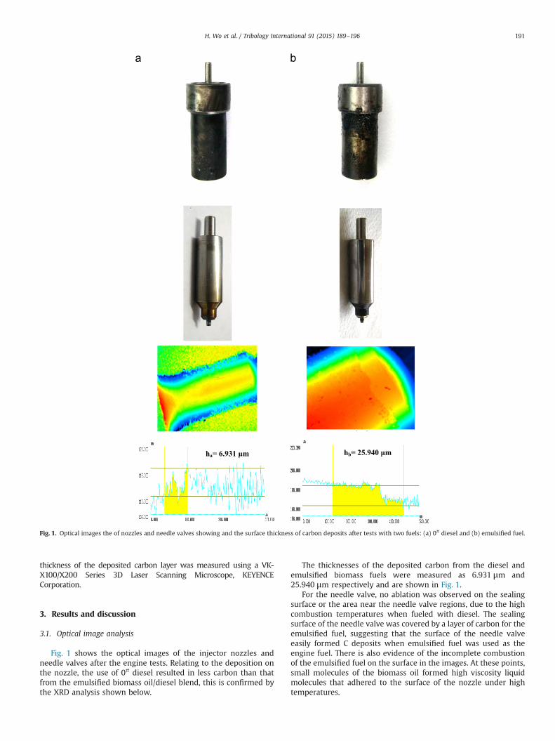
Fig. 1 shows the optical images of the injector nozzles andneedle valves after the engine tests. Relating to the deposition onthe nozzle, the use of 0# diesel resulted in less carbon than thatfrom the emulsified biomass oil/diesel blend, this is confirmed bythe XRD analysis shown below.
The thicknesses of the deposited carbon from the diesel andemulsified biomass fuels were measured as 6.931 μm and25.940 μm respectively and are shown in Fig. 1.
For the needle valve, no ablation was observed on the sealingsurface or the area near the needle valve regions, due to the highcombustion temperatures when fueled with diesel. The sealingsurface of the needle valve was covered by a layer of carbon for theemulsified fuel, suggesting that the surface of the needle valveeasily formed C deposits when emulsified fuel was used as theengine fuel. There is also evidence of the incomplete combustionof the emulsified fuel on the surface in the images. At these points,small molecules of the biomass oil formed high viscosity liquidmolecules that adhered to the surface of the nozzle under hightemperatures.
ha= 6.931 μm hb= 25.940 μm
Fig. 1. Optical images the of nozzles and needle valves showing and the surface thickness of carbon deposits after tests with two fuels: (a) 0# diesel and (b) emulsified fuel.
H. Wo et al. / Tribology International 91 (2015) 189–196 191

Fig. 2 shows the OM images of the end face of the nozzles afterthe tests with the two fuels. The carbon deposition of emulsifiedfuel had a deep color and nest-like structure, which is consistentwith the results mentioned above. The biomass oil in the blend islikely to have been absorbed on the nozzle surface and thencombusted to form carbonaceous matter, which were mixed withthe unburned biomass to form an adhesive body. The carbonac-eous layer was uniform for the diesel fuel.
3.2. XRD analysis
The deposited C was underwent XRD analysis to investigate theformation mechanism of the carbon deposits. Fig. 3 shows the XRDanalysis results of the two kinds of deposit. The diffraction patternof the graphite-2H exhibits four distinct values in the 2θ from 101to 601, which can be indicated as 26.81 (002), 44.51 (101), and 54.91(102) according to the standard card PDF41-1487 database [26].The diffraction pattern of the two samples exhibited only onebroad reflection with intensity maxima at 19.91 and 21.51. Thesefindings suggest that the two carbonaceous materials did not haveclear graphite-like structures [27], rather they were amorphouscarbon; these findings are consistent with the results given in[28–30]. The carbon material of emulsified fuel showed highercrystallinity than that of diesel; this result was further evidencedby the peaks at 19.91 (002), and 43.5 (101) in the carbonaceousmaterial of the emulsified fuel, as shown in Fig. 3. Compared to thestandard card PDF41-1487 database, the spectral peaks were lowerand this is likely to be a result of a finer microcrystalline structureof the graphite. Based on the XRD analysis, the results showed thatemulsified fuel resulted in a higher graphitic degree of carbondeposition than that of the diesel.
Element analysis was conducted for the two C materials by atomicabsorption spectrometry (Perkin-Elmer Model AA800) to understandthe mechanism of carbon deposition [31]. Detailed results are given inTable 3. The C and H contents in the carbonaceous deposit for the
emulsified fuel were higher than that for diesel; as a result of thehigher H2O content and lower heat value. However, the higher heatvalue and lower H2O content of diesel promoted complete combustionandminimal carbon deposition. The N content in the carbon deposit ofthe emulsified fuel was also higher because of the partial combustionof lubricating oil additives. The O content in the emulsified fueldeposits was less than that of diesel because diesel requires a higheroxygen content for combustion. The high O and H2O content in theemulsified fuel caused incomplete combustion and was subsequentlyabsorbed onto the nozzle surface.
3.3. SEM/EDS analysis
SEM (scanning electron microscopy) was used to observe themicrostructures, and zones were selected to analyze the elementalcontents. Fig. 4 shows the micro images of the end face of theneedle valve seat after the two fuels were used. The carbonparticulates from diesel were randomly dispersed. The averageagglomerated particulate diameter was approximately 10–30 μm.No carbon particulates were observed from emulsified fuel; how-ever, large agglomerated matter was found on the surface of theneedle valve seat. The agglomerated particulate matter diameterwas approximately 50 μm. This significant agglomeration phe-nomenon was caused by the combination of carbon particulatesand unburned fuel, thus forming a high viscosity mixture. Thecarbon deposit layer from the emulsified fuel appeared to bedenser and thicker than that from diesel.
Fig. 5 shows the micro images of the needle valve sealingsurface after tests with the two fuels. No carbonaceous depositswere observed on the needle valve sealing surface for diesel. Bycontrast, numerous black oil-like impurities were observed on thesurfaces for the emulsified fuel. These results indicate that thecarbonaceous deposit was caused by the interaction betweenthe unburned fuel and carbon particulates; this result was con-sistent with the abovementioned results.
EDS was used to obtain the element contents in the carbonaceousdeposit to understand the deposition mechanism further. Fig. 6 showsthe SEM images and EDS analysis region of the end face of the needlevalve seat. The EDS analysis results are shown in Table 4.
The results showed that the carbon deposits from the differentfuels had similar elemental compositions, wherein the C contentwas 23.93 wt% for diesel and 25.87 wt% for the emulsified fuel.However, the O and P content varied. The occurrences of S, Zn, andK were attributed to the combustion of additives derived from the
150 μm 150 mμ
Fig. 2. Optical microscopy images of end face of nozzles after tests with two fuels: (a) 0# diesel and (b) emulsified fuel.
10 20 30 40 50 60 70 800
1000
2000
3000
4000
5000
35.2
Diesel
CPS
Emulsification fuel
19.9
Fig. 3. XRD analysis results of carbon deposits.
Table 3Elements analysis of the carbon deposits.
Items C H N O
Diesel 67.57567 5.175667 15.27833 11.970333Emulsified fuel 74.05667 6.605333 14.87967 4.458327
H. Wo et al. / Tribology International 91 (2015) 189–196192

lubricating oil, which could have entered the combustion chambervia blow by or by bypassing the piston rings. Furthermore, while inthe sump the diesel fuel can react with the base oil, additive
package or both, leading to the formation of oil sludge. It can alsolead to a change in viscosity such that the lubricating oil can enterthe chamber through the piston ring pack. Therefore, Zn was
Fig. 4. SEM images of the end face of the needle valve seat after utilization of the two fuels: (a) 0# diesel and (b) emulsified fuel.
Fig. 5. SEM images of needle valve sealing surface after the tests with the two fuels: (a) 0# diesel (b) emulsified fuel.
Fig. 6. SEM images and EDS analysis regions of end face of the needle valve seat after utilization of the two fuels: (a) 0# diesel and (b) emulsified fuel.
Table 4EDS analysis results on the surface of needle valve seats with two fuels. The results are corresponding to the points cross-shaped in Fig. 6 respectively.
Diesel Emulsified fuel
Element Weight (wt%) Atomic (%) Element Weight (wt%) Atomic (%)
C 23.93 33.48 C 25.87 37.86O 55.05 57.81 O 48.64 53.43S 3.71 1.94 S 3.24 1.78Ca 2.73 1.14 Ca 0.94 0.41Fe 7.32 2.20 Fe 8.55 2.69Zn 2.71 0.70 Zn 10.51 2.83Mg 1.53 1.06 K 2.25 1.01Si 0.54 0.33P 2.48 1.35Total 100.00 Total 100.00
H. Wo et al. / Tribology International 91 (2015) 189–196 193
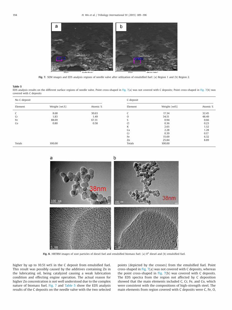
higher by up to 10.51 wt% in the C deposit from emulsified fuel.This result was possibly caused by the additives containing Zn inthe lubricating oil, being catalyzed causing a weak lubricationcondition and effecting engine operation. The actual reason forhigher Zn concentration is not well understood due to the complexnature of biomass fuel. Fig. 7 and Table 5 show the EDS analysisresults of the C deposits on the needle valve with the two selected
points (depicted by the crosses) from the emulsified fuel. Pointcross-shaped in Fig. 7(a) was not covered with C deposits, whereasthe point cross-shaped in Fig. 7(b) was covered with C deposits.The EDS spectra from the region not affected by C depositionshowed that the main elements included C, Cr, Fe, and Co, whichwere consistent with the compositions of high-strength steel. Themain elements from region covered with C deposits were C, Fe, O,
Fig. 7. SEM images and EDS analysis regions of needle valve after utilization of emulsified fuel: (a) Region 1 and (b) Region 2.
Table 5EDS analysis results on the different surface regions of needle valve. Point cross-shaped in Fig. 7(a) was not covered with C deposits; Point cross-shaped in Fig. 7(b) wascovered with C deposits
No C-deposit C-deposit
Element Weight (wt.%) Atomic % Element Weight (wt%) Atomic %
C 8.68 30.63 C 17.34 32.45Cr 1.83 1.49 O 34.51 48.49Fe 88.69 67.31 S 0.94 0.66Co 0.80 0.58 Cl 0.36 0.23
K 2.65 1.52Ca 2.28 1.28Cr 0.39 0.17Fe 15.69 6.32Zn 25.84 8.89
Totals 100.00 Totals 100.00
Fig. 8. HRTRM images of soot particles of diesel fuel and emulsified biomass fuel: (a) 0# diesel and (b) emulsified fuel.
H. Wo et al. / Tribology International 91 (2015) 189–196194
S, Cl, K, Ca, and Zn. On the other hand, S, Cl, Ca, and Zn originatedfrom the combustion of lubricating oil, and K was derived from thecomposition of biomass oil in the emulsified fuel. The resultsshowed that the surface of the needle valve was covered with Cdeposits of varying thicknesses.
3.4. Mechanism of carbonaceous deposition
The formation of carbonaceous deposit could be further under-stood by studying the soot particles extracted from the oil sump ofthe mode S195 diesel engine. Fig. 8 shows the HRTRM images ofsoot particles of diesel fuel and emulsified biomass fuel. It wasfound that the soot particles from both fuels were sphere-like instructure and were linked in a chain. The average diameter of theprimary soot particles were about 38 nm, measured from theimages using the Nano measurer software, which was similar tothe results from the TEM images given in [32,33].
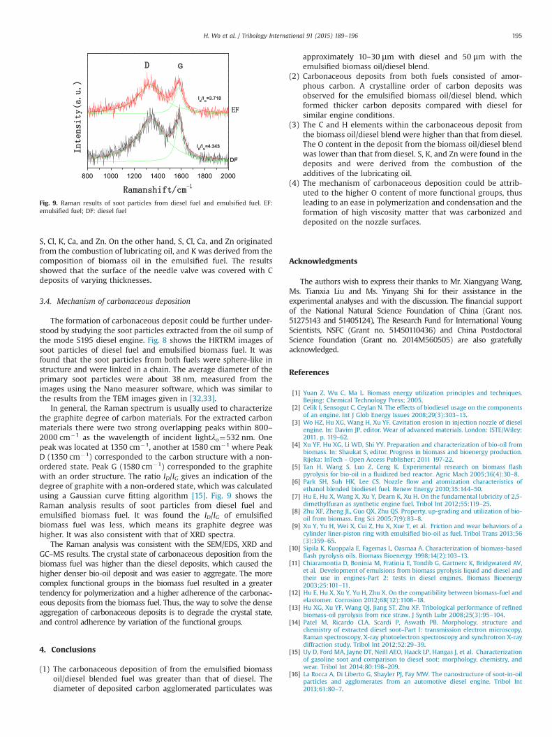
In general, the Raman spectrum is usually used to characterizethe graphite degree of carbon materials. For the extracted carbonmaterials there were two strong overlapping peaks within 800–2000 cm�1 as the wavelength of incident lightλo¼532 nm. Onepeak was located at 1350 cm�1, another at 1580 cm�1 where PeakD (1350 cm�1) corresponded to the carbon structure with a non-ordered state. Peak G (1580 cm�1) corresponded to the graphitewith an order structure. The ratio ID/IG gives an indication of thedegree of graphite with a non-ordered state, which was calculatedusing a Gaussian curve fitting algorithm [15]. Fig. 9 shows theRaman analysis results of soot particles from diesel fuel andemulsified biomass fuel. It was found the ID/IG of emulsifiedbiomass fuel was less, which means its graphite degree washigher. It was also consistent with that of XRD spectra.
The Raman analysis was consistent with the SEM/EDS, XRD andGC–MS results. The crystal state of carbonaceous deposition from thebiomass fuel was higher than the diesel deposits, which caused thehigher denser bio-oil deposit and was easier to aggregate. The morecomplex functional groups in the biomass fuel resulted in a greatertendency for polymerization and a higher adherence of the carbonac-eous deposits from the biomass fuel. Thus, the way to solve the denseaggregation of carbonaceous deposits is to degrade the crystal state,and control adherence by variation of the functional groups.
4. Conclusions
(1) The carbonaceous deposition of from the emulsified biomassoil/diesel blended fuel was greater than that of diesel. Thediameter of deposited carbon agglomerated particulates was
approximately 10–30 μm with diesel and 50 μm with theemulsified biomass oil/diesel blend.
(2) Carbonaceous deposits from both fuels consisted of amor-phous carbon. A crystalline order of carbon deposits wasobserved for the emulsified biomass oil/diesel blend, whichformed thicker carbon deposits compared with diesel forsimilar engine conditions.
(3) The C and H elements within the carbonaceous deposit fromthe biomass oil/diesel blend were higher than that from diesel.The O content in the deposit from the biomass oil/diesel blendwas lower than that from diesel. S, K, and Zn were found in thedeposits and were derived from the combustion of theadditives of the lubricating oil.
(4) The mechanism of carbonaceous deposition could be attrib-uted to the higher O content of more functional groups, thusleading to an ease in polymerization and condensation and theformation of high viscosity matter that was carbonized anddeposited on the nozzle surfaces.
Acknowledgments
The authors wish to express their thanks to Mr. Xiangyang Wang,Ms. Tianxia Liu and Ms. Yinyang Shi for their assistance in theexperimental analyses and with the discussion. The financial supportof the National Natural Science Foundation of China (Grant nos.51275143 and 51405124), The Research Fund for International YoungScientists, NSFC (Grant no. 51450110436) and China PostdoctoralScience Foundation (Grant no. 2014M560505) are also gratefullyacknowledged.
References
[1] Yuan Z, Wu C, Ma L. Biomass energy utilization principles and techniques.Beijing: Chemical Technology Press; 2005.
[2] Celik I, Sensogut C, Ceylan N. The effects of biodiesel usage on the componentsof an engine. Int J Glob Energy Issues 2008;29(3):303–13.
[3] Wo HZ, Hu XG, Wang H, Xu YF. Cavitation erosion in injection nozzle of dieselengine. In: Davim JP, editor. Wear of advanced materials. London: ISTE/Wiley;2011. p. 119–62.
[4] Xu YF, Hu XG, Li WD, Shi YY. Preparation and characterization of bio-oil frombiomass. In: Shaukat S, editor. Progress in biomass and bioenergy production.Rijeka: InTech - Open Access Publisher; 2011 197-22.
[5] Tan H, Wang S, Luo Z, Ceng K. Experimental research on biomass flashpyrolysis for bio-oil in a fluidized bed reactor. Agric Mach 2005;36(4):30–8.
[6] Park SH, Suh HK, Lee CS. Nozzle flow and atomization characteristics ofethanol blended biodiesel fuel. Renew Energy 2010;35:144–50.
[7] Hu E, Hu X, Wang X, Xu Y, Dearn K, Xu H. On the fundamental lubricity of 2,5-dimethylfuran as synthetic engine fuel. Tribol Int 2012;55:119–25.
[8] Zhu XF, Zheng JL, Guo QX, Zhu QS. Property, up-grading and utilization of bio-oil from biomass. Eng Sci 2005;7(9):83–8.
[9] Xu Y, Yu H, Wei X, Cui Z, Hu X, Xue T, et al. Friction and wear behaviors of acylinder liner-piston ring with emulsified bio-oil as fuel. Tribol Trans 2013;56(3):359–65.
[10] Sipila K, Kuoppala E, Fagemas L, Oasmaa A. Characterization of biomass-basedflash pyrolysis oils. Biomass Bioenergy 1998;14(2):103–13.
[11] Chiaramontia D, Boninia M, Fratinia E, Tondib G, Gartnerc K, Bridgwaterd AV,et al. Development of emulsions from biomass pyrolysis liquid and diesel andtheir use in engines-Part 2: tests in diesel engines. Biomass Bioenergy2003;25:101–11.
[12] Hu E, Hu X, Xu Y, Yu H, Zhu X. On the compatibility between biomass-fuel andelastomer. Corrosion 2012;68(12):1108–18.
[13] Hu XG, Xu YF, Wang QJ, Jiang ST, Zhu XF. Tribological performance of refinedbiomass-oil pyrolysis from rice straw. J Synth Lubr 2008;25(3):95–104.
[14] Patel M, Ricardo CLA, Scardi P, Aswath PB. Morphology, structure andchemistry of extracted diesel soot–Part I: transmission electron microscopy,Raman spectroscopy, X-ray photoelectron spectroscopy and synchrotron X-raydiffraction study. Tribol Int 2012;52:29–39.
[15] Uy D, Ford MA, Jayne DT, Neill AEO, Haack LP, Hangas J, et al. Characterizationof gasoline soot and comparison to diesel soot: morphology, chemistry, andwear. Tribol Int 2014;80:198–209.
[16] La Rocca A, Di Liberto G, Shayler PJ, Fay MW. The nanostructure of soot-in-oilparticles and agglomerates from an automotive diesel engine. Tribol Int2013;61:80–7.
800 1000 1200 1400 1600 1800 2000
Fig. 9. Raman results of soot particles from diesel fuel and emulsified fuel. EF:emulsified fuel; DF: diesel fuel
H. Wo et al. / Tribology International 91 (2015) 189–196 195

[17] Barker J, Richards P, Snape C, Meredith W. Diesel injector deposits – An issuethat has evolved with engine technology. SAE Paper no: -01-1923, 2011.
[18] Barker, J, Snape, C, Scurr, D. Information on the Aromatic Structure of InternalDiesel Injector Deposits From Time of Flight Secondary Ion Mass Spectrometry(ToF-SIMS), SAE Paper -01-1387, 2014.
[19] Barker J, Innospec JR, Snape C, Scurr D, Meredith W. Spectroscopic studies ofinternal injector deposits (IDID) resulting from the use of non-commercial lowmolecular weight polyisobutylenesuccinimide (PIBSI). SAE Paper No: -01-2720, 2014.
[20] Mendiratta RL, Singh D. Effect of base oil and additives on combustionchamber and intake valve deposits formation in IC engine. SAE Paper No:-28-0089, 2004.
[21] Parsinejad F, Biggs W. Direct injection spark ignition engine deposit analysis:Combustion chamber and intake valve deposits. SAE Paper No: -01-2110, 2011.
[22] Zerda TW, Yuan X, Moore SM, Leon y Leon CA. Surface area, pore sizedistribution and microstructure of combustion engine deposits. Carbon1999;37(12):1999–2009.
[23] Zerda TW, Yuan X, Moore SM. Effects of fuel additives on the microstructure ofcombustion engine deposits. Carbon 2001;39(10):1589–97.
[24] Kalghatgi GT. Combustion chamber deposits and knock in a spark ignitionengine-some additive and fuel effects. SAE Paper No: 962009.
[25] Fay MW, La Rocca A, Shayler PJ. TEM and HRTEM of Soot-in-oil particles andagglomerates from internal combustion engines. J Phys: Conf Ser2014;522:012072. http://dx.doi.org/10.1088/1742-6596/522/1/012072.
[26] Sadezky A, Muckenhuber H, Grothe H, Niessner R, Poschl U. Raman micro-spectroscopy of soot and related carbonaceous materials: spectral analysis andstructural information. Carbon 2005;43:1731–42.
[27] Zhang D. Study on the application of emulsified on the engine and combustionmechanism. Diss Dalian Univ Tech; Dalian; 2002.
[28] Randy L, Vander Wal, Bryg Vicky M, Hays Michael D. Fingerprinting soot(towards source identification) physical structure and chemical composition.J Aerosol Sci 2010;41:108–17.
[29] Lapuerta M, Rodrıguez-Fernandez J, Agudelo JR. Diesel particulate emissionsfrom used cooking oil biodiesel. Bioresource Technol 2008;99:731–40.
[30] La Rocca A, Di Liberto G, Shayler P, Parmenter C, Fay M. A novel diagnosticstool for measuring soot agglomerates size distribution in used automotivelubricant oils. SAE Int J Fuels Lubr 2014;7(1):2014–01-1479.
[31] Celik I, Aydin O. Effects of B100 biodiesel on injector and pump piston. TribolTrans 2011;54:424–31.
[32] Hu E, Hu X, Liu T, Liu Y, Song R, Chen Y. Investigation of morphology, structureand composition of biomass-oil soot particles. Appl Surf Sci2013;270:596–603.
[33] La Rocca A, Di Liberto G, Shayler PJ, Parmenter CDJ, Fay MW. Application ofnanoparticle tracking analysis platform for the measurement of soot-in-oilagglomerates from automotive engines. Tribol Int 2014;70:142–7.
H. Wo et al. / Tribology International 91 (2015) 189–196196