Embed Size (px)
Citation preview

Morphing and AnimationGPU GraphicsGary J. Katz
University of Pennsylvania CIS 665
Adapted from articles taken from ShaderX 3, 4 and 5And GPU Gems 1
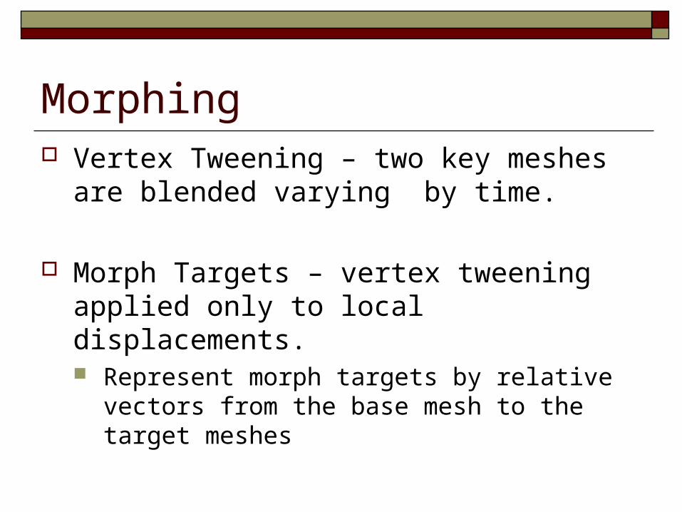
Morphing Vertex Tweening – two key meshes are
blended varying by time.
Morph Targets – vertex tweening applied only to local displacements. Represent morph targets by relative vectors from
the base mesh to the target meshes

Morph Target Animation Morph Target Animation – one base mesh can
morph into multiple targets at the same time. Facial animation Muscle Deformation

Morph Target Animation
1
23
45
6 7 89
1011
12 12 3 4 5
6
7 8 9 1011 12
Linear Interpolation: Relative: PositionOutput = PositionSource + (PositionDestination * Factor)Absolute: PositionOutput = PositionSource + (PositionDestination – PositionSource)*Factor

Relative vs. Absolute
4
3 < 7, 3, 9 >
< 4, 3, 5>
RelativeRelative AbsoluteAbsolute

Constraints1. Number of vertices must be the same
2. Faces and attributes must be the same
3. Material must be equal
4. Textures must be the same
5. Shaders, etc must be the same
Useful only where skinning fails!

Data Structures for Morphing DirectX allows for flexible vertex formats Unsure if OpenGL supports flexible formats Position 1 holds the relative position for the morph target
D3DVERTEXELEMENT9 pStandardMeshDeclaration[] ={
{ 0, 0, D3DDECLTYPE_FLOAT3, D3DDECLMETHOD_DEFAULT,D3DDECLUSAGE_POSITION, 0 },
{ 0, 12, D3DDECLTYPE_FLOAT3, D3DDECLMETHOD_DEFAULT,D3DDECLUSAGE_POSITION, 1 },
{ 0, 24, D3DDECLTYPE_FLOAT3, D3DDECLMETHOD_DEFAULT,D3DDECLUSAGE_NORMAL, 0 },
{ 0, 32, D3DDECLTYPE_FLOAT3, D3DDECLMETHOD_DEFAULT,D3DDECLUSAGE_TEXCOORD, 0 },
D3DDECL_END()}
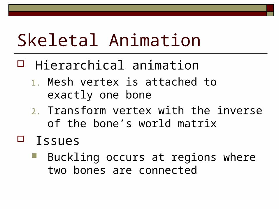
Skeletal Animation Hierarchical animation
1. Mesh vertex is attached to exactly one bone
2. Transform vertex with the inverse of the bone’s world matrix
Issues Buckling occurs at regions where two bones are
connected
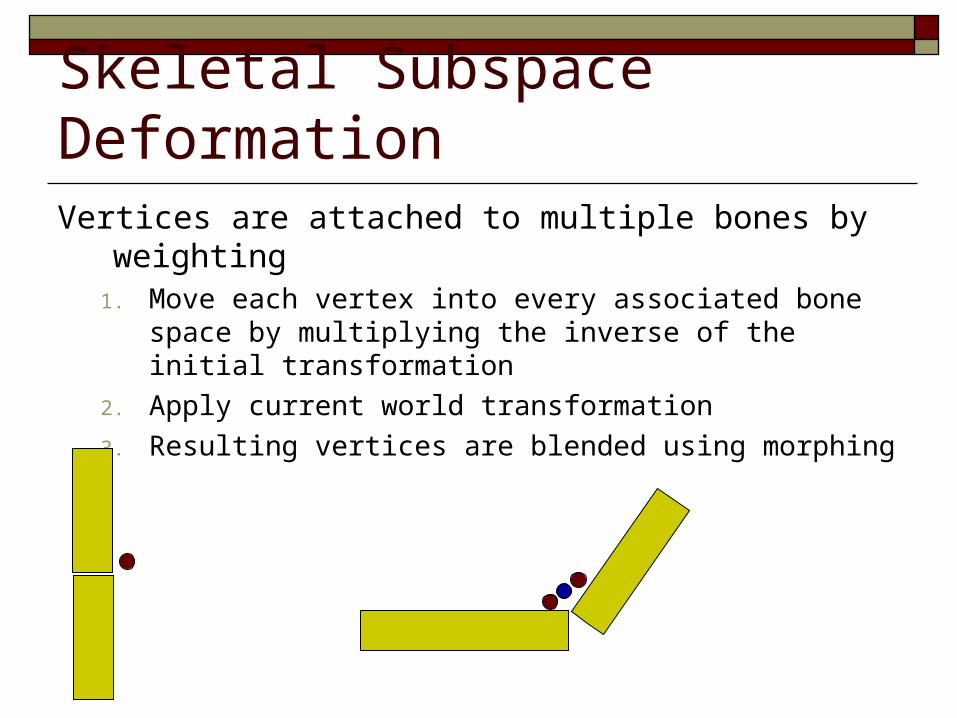
Skeletal Subspace DeformationVertices are attached to multiple bones by weighting
1. Move each vertex into every associated bone space by multiplying the inverse of the initial transformation
2. Apply current world transformation
3. Resulting vertices are blended using morphing

Shader Model 2.0 Approach Go into Dawn demo here
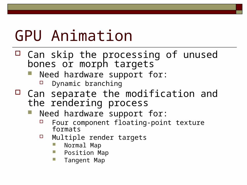
GPU Animation Can skip the processing of unused bones or morph
targets Need hardware support for:
Dynamic branching Can separate the modification and the rendering
process Need hardware support for:
Four component floating-point texture formats Multiple render targets
Normal Map Position Map Tangent Map

Method 1 Hold the vertex data in texture arrays Manipulate the data in the pixel shader Re-output to texture arrays Pass the output as input to vertex shader

Storage ProceduresIf:
vertex array is one-dimensional
frame buffer is two-dimensional
index2D.x = index % textureWidth;index2D.y = index / textureWidth;
index = index2D.y * textureWidth + index2D.x;

Redefining the ViewDraw a rectangle of coordinates
(0,0), (0,1), (0,1), (1,1)
Remap them using the following vertex program
float4 VS(float4 index2D: POSITION0, out float4 outIndex2D : TEXCOORD0) : POSITION {
outIndex2D = index2D;return float4(2 * index2D.x – 1, -2 * index2D.y + 1, 0, 1);
}
(-1, 1), (1,1), (-1,-1), (1,-1)

GPU Animation Pixel Shader
float2 halfTexel = float2(.5/texWidth, .5/texHeight);float4 PS(float4 index2D : TEXCOORD0,
out float4 position : COLOR0,out float4 normal : COLOR1, ...)
{ index2D.xy += halfTexel; float4 vertAttr0 = tex2Dlod(Sampler0, index2D); float4 vertAttr1 = tex2Dlod(Sampler1, index2D); ... ... // perform modifications and assign the final // vertex attributes to the output registers}

AnalysisAdvantageAdvantage Keeps vertex and geometry processing units workload at a
minimum Why is this good?
Good for copy operations and vertex tweeningDisadvantageDisadvantage Per-vertex data has to be accessed through texture lookups Number of constant registers is less in pixel shader (224) than
vertex shader (256) Can not divide modification process into several pieces
because only a single quad is drawn Therefore, Constant registers must hold all bone matrices and
morph target weights for entire object

Method 2 Apply modifications in the vertex shader, do nothing
in the pixel shader Destination pixel is specified explicitly as a vertex
shader input Still writing all vertices to a textureAdvantageAdvantage
Can easily segment the modification groupsDisadvantageDisadvantage
Speed issues make this method impractical
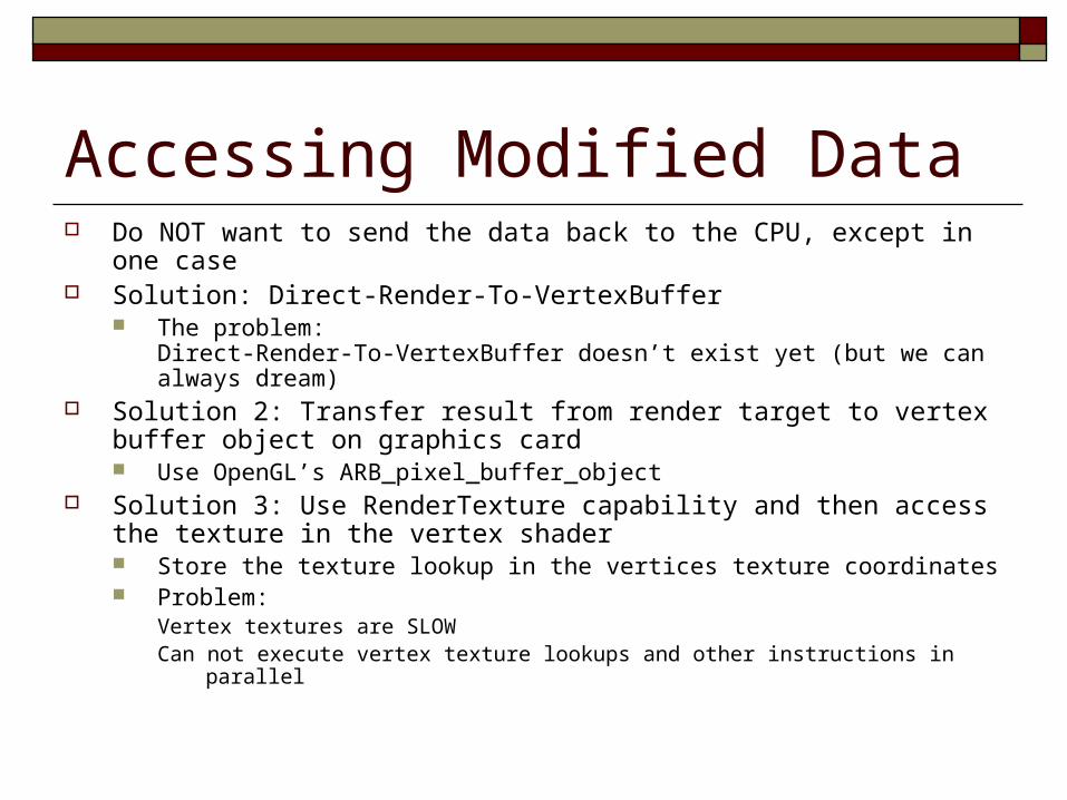
Accessing Modified Data Do NOT want to send the data back to the CPU, except in one case Solution: Direct-Render-To-VertexBuffer
The problem:Direct-Render-To-VertexBuffer doesn’t exist yet (but we can always dream)
Solution 2: Transfer result from render target to vertex buffer object on graphics card Use OpenGL’s ARB_pixel_buffer_object
Solution 3: Use RenderTexture capability and then access the texture in the vertex shader Store the texture lookup in the vertices texture coordinates Problem:
Vertex textures are SLOWCan not execute vertex texture lookups and other instructions in parallel

Performance Issues Preferable to perform modification and
rendering in single pass Accessing vertex attributes using vertex
texturing is always slower than performing a fast copy within video memory
Accessing morph in a vertex texture makes the application too slow, must use constants

Usage To get real speed advantage use a hybrid CPU GPU
approach1. Let the CPU compute the final vertex attributes used during
rendering frames n and n+k2. Let the GPU perform vertex tweening at frames greater than
n and smaller than n+k3. Phase shift the animations between characters so that the
processors do not have peak loads Advantage
Vertex tweening is supported on almost all hardware No restrictions on modification algorithms because it is performed
on CPU
Massive Character Animation Can perform simple AI effects Each pixel of output texture holds one
character’s state Pixel shader computes next state State is used to determine which animation to
use

Simulating Character Behavior Implement Finite State Machine in Pixel Shader
Walk
Turn
If no Obstacle
Run
If Chased
If Obstacle
If Chased
If Obstacle

Implementing an FSM on GPUUse dependent texture lookups
Agent-space maps: Contain information about the state of characters (position, state, frame)
World-space image maps: Contain information about the environment to influence the behavior of the character
FSM Maps: Contain information about the behavior for each state and about transitions between states. Rows group transitions within the same state Columns contain conditions to trigger transitions