Embed Size (px)
Citation preview
Rob Hamann; 16-10-2018 - 1
Fokker G.I A Reconnaissance MPM1 injection kit Monoplane strategic reconnaissance aircraft and light bomber
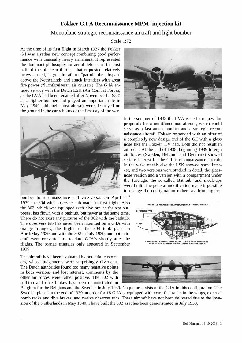
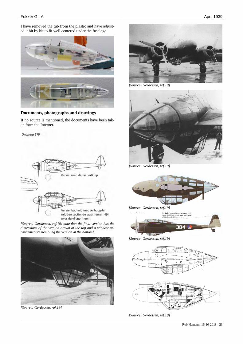
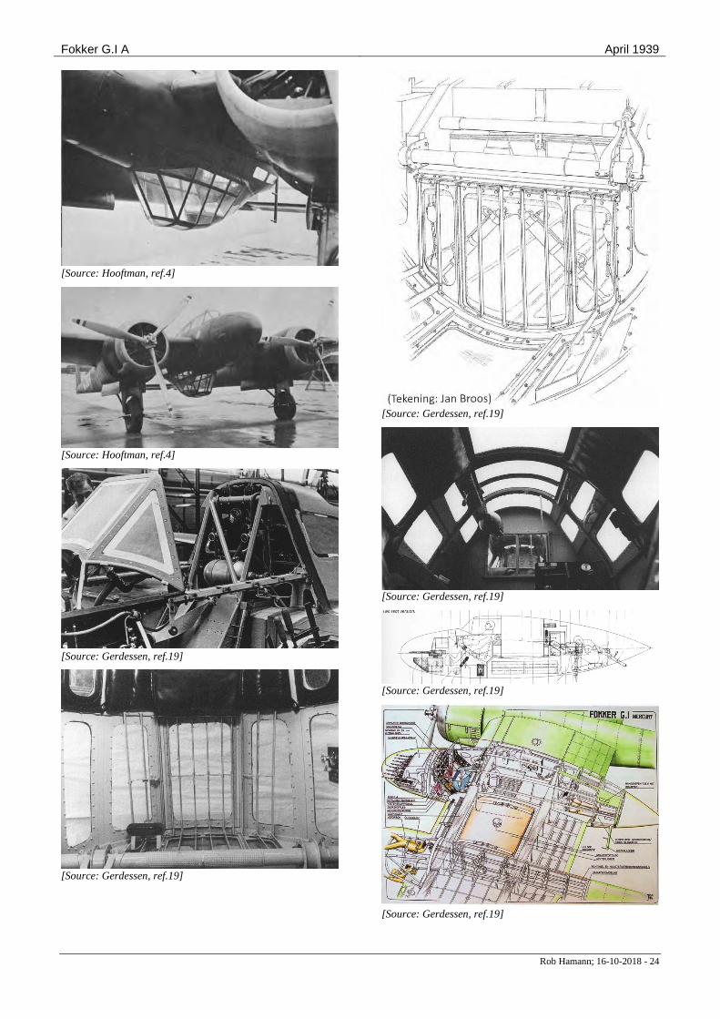
Scale 1:72 At the time of its first flight in March 1937 the Fokker G.I was a rather new concept combining good perfor-mance with unusually heavy armament. It represented the dominant philosophy for aerial defence in the first half of the nineteen thirties, that requested relatively heavy armed, large aircraft to “patrol” the airspace above the Netherlands and attack intruders with great fire power (“luchtkruisers”, air cruisers). The G.IA en-tered service with the Dutch LSK (Air Combat Forces, as the LVA had been renamed after November 1, 1938) as a fighter-bomber and played an important role in May 1940, although most aircraft were destroyed on the ground in the early hours of the first day of the war.
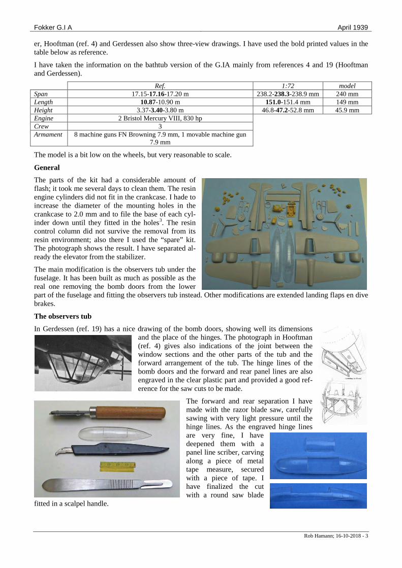
In the summer of 1938 the LVA issued a request for proposals for a multifunctional aircraft, which could serve as a fast attack bomber and a strategic recon-naissance aircraft. Fokker responded with an offer of a completely new design and of the G.I with a glass nose like the Fokker T.V had. Both did not result in an order. At the end of 1938, beginning 1939 foreign air forces (Sweden, Belgium and Denmark) showed serious interest for the G.I as reconnaissance aircraft. In the wake of this also the LSK showed some inter-est, and two versions were studied in detail, the glass-nose version and a version with a compartment under the fuselage, the so-called Bathtub, and mock-ups were built. The general modification made it possible to change the configuration rather fast from fighter-
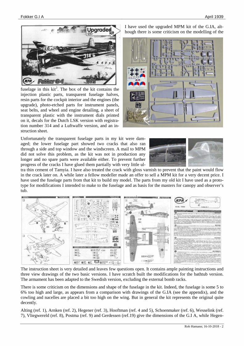
bomber to reconnaissance and vice-versa. On April 21st 1939 the 304 with observers tub made its first flight. Also the 302, which was equipped with dive brakes for test pur-poses, has flown with a bathtub, but never at the same time. There do not exist any pictures of the 302 with the bathtub. The observers tub has never been mounted on a G.IA with orange triangles; the flights of the 304 took place in April/May 1939 and with the 302 in July 1939, and both air-craft were converted to standard G.IA’s shortly after the flights. The orange triangles only appeared in September 1939.
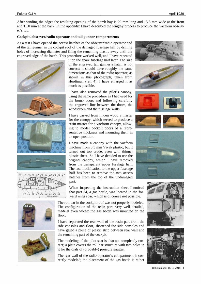
The aircraft have been evaluated by potential custom-ers, whose judgements were surprisingly divergent. The Dutch authorities found too many negative points in both versions and lost interest, comments by the other air forces were rather positive. The 302 with bathtub and dive brakes has been demonstrated in Belgium for the Belgians and the Swedish in July 1939. No picture exists of the G.IA in this configuration. The Swedish placed at the end of 1939 an order for 18 G.IA’s, equipped with extra fuel tanks in the wings, external bomb racks and dive brakes, and twelve observer tubs. These aircraft have not been delivered due to the inva-sion of the Netherlands in May 1940. I have built the 302 as it has been demonstrated in July 1939.
Fokker G.I A April 1939
Rob Hamann; 16-10-2018 - 2
I have used the upgraded MPM kit of the G.IA, alt-hough there is some criticism on the modelling of the
fuselage in this kit2. The box of the kit contains the injection plastic parts, transparent fuselage halves, resin parts for the cockpit interior and the engines (the upgrade), photo-etched parts for instrument panels, seat belts, and wheel and engine detailing, a sheet of transparent plastic with the instrument dials printed on it, decals for the Dutch LSK version with registra-tion number 314 and a Luftwaffe version, and an in-struction sheet.
Unfortunately the transparent fuselage parts in my kit were dam-aged; the lower fuselage part showed two cracks that also ran through a side and top window and the windscreen. A mail to MPM did not solve this problem, as the kit was not in production any longer and no spare parts were available either. To prevent further progress of the cracks I have glued them partially with very little ul-tra thin cement of Tamyia. I have also treated the crack with gloss varnish to prevent that the paint would flow in the crack later on. A while later a fellow modeller made an offer to sell a MPM kit for a very decent price. I have used the fuselage parts from that kit to build my model. The parts from my old kit I have used as a proto-type for modifications I intended to make to the fuselage and as basis for the masters for canopy and observer’s tub.
The instruction sheet is very detailed and leaves few questions open. It contains ample painting instructions and three view drawings of the two basic versions. I have scratch built the modifications for the bathtub version. The armament has been adapted to the Swedish version, excluding the external bomb racks.
There is some criticism on the dimensions and shape of the fuselage in the kit. Indeed, the fuselage is some 5 to 6% too high and large, as appears from a comparison with drawings of the G.IA (see the appendix), and the cowling and nacelles are placed a bit too high on the wing. But in general the kit represents the original quite decently.
Alting (ref. 1), Arnken (ref. 2), Hegener (ref. 3), Hooftman (ref. 4 and 5), Schoenmaker (ref. 6), Wesselink (ref. 7), Vliegwereld (ref. 8), Postma (ref. 9) and Gerdessen (ref.19) give the dimensions of the G.I A, while Hegen-
Fokker G.I A April 1939
Rob Hamann; 16-10-2018 - 3
er, Hooftman (ref. 4) and Gerdessen also show three-view drawings. I have used the bold printed values in the table below as reference.
I have taken the information on the bathtub version of the G.IA mainly from references 4 and 19 (Hooftman and Gerdessen).
Ref. 1:72 model Span 17.15-17.16-17.20 m 238.2-238.3-238.9 mm 240 mm Length 10.87-10.90 m 151.0-151.4 mm 149 mm Height 3.37-3.40-3.80 m 46.8-47.2-52.8 mm 45.9 mm Engine 2 Bristol Mercury VIII, 830 hp Crew 3 Armament 8 machine guns FN Browning 7.9 mm, 1 movable machine gun
7.9 mm
The model is a bit low on the wheels, but very reasonable to scale.
General
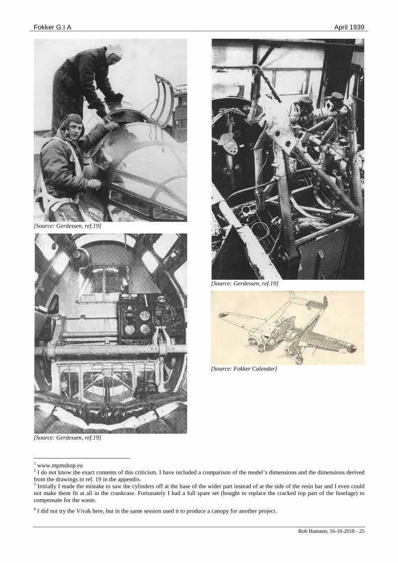
The parts of the kit had a considerable amount of flash; it took me several days to clean them. The resin engine cylinders did not fit in the crankcase. I hade to increase the diameter of the mounting holes in the crankcase to 2.0 mm and to file the base of each cyl-inder down until they fitted in the holes3. The resin control column did not survive the removal from its resin environment; also there I used the “spare” kit. The photograph shows the result. I have separated al-ready the elevator from the stabilizer.
The main modification is the observers tub under the fuselage. It has been built as much as possible as the real one removing the bomb doors from the lower part of the fuselage and fitting the observers tub instead. Other modifications are extended landing flaps en dive brakes.
The observers tub
In Gerdessen (ref. 19) has a nice drawing of the bomb doors, showing well its dimensions and the place of the hinges. The photograph in Hooftman (ref. 4) gives also indications of the joint between the window sections and the other parts of the tub and the forward arrangement of the tub. The hinge lines of the bomb doors and the forward and rear panel lines are also engraved in the clear plastic part and provided a good ref-erence for the saw cuts to be made.
The forward and rear separation I have made with the razor blade saw, carefully sawing with very light pressure until the hinge lines. As the engraved hinge lines are very fine, I have deepened them with a panel line scriber, carving along a piece of metal tape measure, secured with a piece of tape. I have finalized the cut with a round saw blade
fitted in a scalpel handle.
Fokker G.I A April 1939
Rob Hamann; 16-10-2018 - 4
After sanding the edges the resulting opening of the bomb bay is 29 mm long and 15.5 mm wide at the front and 15.0 mm at the back. In the appendix I have described the lengthy process to produce the vacform observ-er’s tub.
Cockpit, observer/radio operator and tail gunner compartments
As a test I have opened the access hatches of the observer/radio operator and of the tail gunner in the cockpit roof of the damaged fuselage half by drilling holes of increasing diameter and filing the remaining plastic away until the engraved edge of the hatch. This procedure worked well, and I have repeated
it on the spare fuselage half later. The size of the engraved tail gunner’s hatch is not correct; it should have roughly the same dimensions as that of the radio operator, as shown in this photograph, taken from Hooftman (ref. 4). I have enlarged it as much as possible.
I have also removed the pilot’s canopy, using the same procedure as I had used for the bomb doors and following carefully the engraved line between the doors, the windscreen and the fuselage walls.
I have carved from linden wood a master for the canopy, which served to produce a resin master for a vacform canopy, allow-ing to model cockpit doors of a repre-sentative thickness and mounting them in an open position.
I have made a canopy with the vacform machine from 0.5 mm Vivak plastic, but it turned out too crude, even with thinner plastic sheet. So I have decided to use the original canopy, which I have removed from the transparent upper fuselage half. The last modification to the upper fuselage half has been to remove the two access hatches from the top of the undamaged part.
When inspecting the instruction sheet I noticed that part 34, a gas bottle, was located in the for-ward wing spar, which is of course not possible.
The roll bar in the cockpit roof was not properly modeled. The configuration of the resin part, very well detailed, made it even worse: the gas bottle was mounted on the floor.
I have separated the rear wall of the resin part from the side consoles and floor, shortened the side consoles and have glued a piece of plastic strip between rear wall and the remaining part of the cockpit.
The modeling of the pilot seat is also not completely cor-rect; a plate covers the roll bar structure with two holes in it for the dials of (probably) pressure gauges.
The rear wall of the radio operator’s compartment is cor-rectly modeled; the placement of the gas bottle is rather

Fokker G.I A April 1939
Rob Hamann; 16-10-2018 - 5
arbitrary, but photographs are also not consistent.
The seat, however, is the standard seat, and will have to be replaced by a folding seat to give access to the ob-server’s tub.
Part of the floor must be hinged and the framework normally separating the compartment from the bomb bay (not present in the model) must be removed. All photographs have been taken from Gerdessen (ref. 19).
For the general arrangement of all compartments I have also used a drawing in Gerdessen at the left. A
second drawing in Gerdessen (above) shows the tail gunner with his feet in the rear part of the observer’s compartment. This is not possible, as the skin of the lower part of the rear fuselage cannot be removed, as
is clearly shown in a picture taken during wing and fuselage assembly in the factory (second G.IA from the front, upside down in the picture).
Another modification I have made is the introduction of a separation between the radio operator/observer com-partment and the bomb bay, which is not present in the model. The presence of the observers tub provides better visibility of the interior and some details, like the hatch in the floor and the folding seat for the radio opera-tor/observer have also to be modeled. A second function of the floor was to align forward and rear interior parts well with each other and the opening of the bomb bay.
I have made the floor from 0.4 mm plastic sheet and have opened up the center. As the lower part of the two interior parts is not on the same height relative to the fuselage, I have also introduced a piece of 1 mm plastic to compensate for it.
Next I have made hinges the observer’s seat and for the moveable part of the floor from small pieces of 1 x 1 mm U-profile. When doing that I noticed that I had made the opening too large; the oxygen bottle would block the hatch, so I had to make it smaller. I have glued a strip in the opening and have at the same time
mounted some profiles between the two fuselage trusses to get a better sta-bility of the assembly. The profiles fit just next to the hatch openings in the top of the cabin.
I have removed the bars from the aft bomb bay separation and have replaced them by finer bars made from 0.5 mm styrene rod. I have painted all wooden and metal parts of the fuselage framework light grey, all equipment elements dark grey and the oxygen bottles green. I had to use the resin control column from the spare copy; the original es-caped with unknown destination.
Fokker G.I A April 1939
Rob Hamann; 16-10-2018 - 6
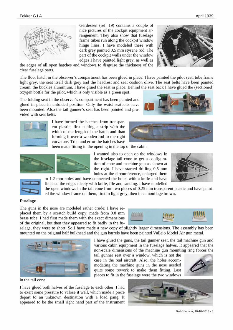
Gerdessen (ref. 19) contains a couple of nice pictures of the cockpit equipment ar-rangement. They also show that fuselage frame tubes run along the cockpit window hinge lines. I have modeled these with dark grey painted 0,5 mm styrene rod. The part of the cockpit walls under the window edges I have painted light grey, as well as
the edges of all open hatches and windows to disguise the thickness of the clear fuselage parts.
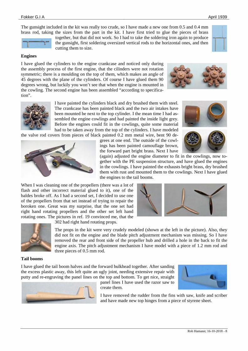
The floor hatch in the observer’s compartment has been glued in place. I have painted the pilot seat, tube frame light grey, the seat itself dark grey and the headrest and seat cushion olive. The seat belts have been painted cream, the buckles aluminium. I have glued the seat in place. Behind the seat back I have glued the (sectioned) oxygen bottle for the pilot, which is only visible as a green spot.
The folding seat in the observer’s compartment has been painted and glued in place in unfolded position. Only the waist seatbelts have been mounted. Also the tail gunner’s seat has been painted and pro-vided with seat belts.
I have formed the hatches from transpar-ent plastic, first cutting a strip with the width of the length of the hatch and than forming it over a wooden rod to the right curvature. Trial and error the hatches have been made fitting in the opening in the top of the cabin.
I wanted also to open op the windows in the fuselage tail cone to get a configura-tion of cone and machine gun as shown at the right. I have started drilling 0.5 mm holes at the circumference, enlarged them
to 1.2 mm holes and have connected the holes with a knife and have finished the edges nicely with knife, file and sanding. I have modelled the open windows in the tail cone from two pieces of 0.25 mm transparent plastic and have paint-ed the window frame on them, first in light grey, then in camouflage brown.
Fuselage
The guns in the nose are modeled rather crude; I have re-placed them by a scratch build copy, made from 0.8 mm brass tube. I had first made them with the exact dimensions of the original, but then they appeared to fit badly in the fu-selage, they were to short. So I have made a new copy of slightly larger dimensions. The assembly has been mounted on the original half bulkhead and the gun barrels have been painted Vallejo Model Air gun metal.
I have glued the guns, the tail gunner seat, the tail machine gun and various cabin equipment in the fuselage halves. It appeared that the non-scale dimensions of the machine gun mounting ring forces the tail gunner seat over a window, which is not the case in the real aircraft. Also, the holes accom-modating the machine guns in the nose needed quite some rework to make them fitting. Last pieces to fit in the fuselage were the two windows
in the tail cone.
I have glued both halves of the fuselage to each other. I had to exert some pressure to vclose it well, which made a piece depart to an unknown destination with a load pang. It appeared to be the small right hand part of the instrument

Fokker G.I A April 1939
Rob Hamann; 16-10-2018 - 7
panel, which apparently was obstructing the fuselage closure. Here also the fact that I had two kits saved the operation. I have painted a second copy of the PE dark grey and glued it on a black painted piece of thin styrene sheet.
After producing the obervers tub from 0.3 mm clear plastic sheet (see the annex) I have mounted that temporarily under the fuselage and have marked the forward frame and aft section with tape, taking care that they were vertical. As the tub is mounted to a part of the fuselage that is dark brown I have assumed the tub being painted brown also, which is confirmed by the black and white photographs showing no difference in the grey shade of tub
and fuselage.
Next I have painted the other two vertical frames. This time I have used the narrow, flexible white masking tape; it leads to considerably less paint flowing under it at curvatures and in corners where the painted frames have to cross. I have also made the two outer machine guns from 0.8 mm brass tube and glued them in the nose.
The outline of the middle horizontal frame members have been taped with the flexible masking. At the places where it crosses the vertical frames I have pressed it against the painted frame with a toothpick. The result was
quite satisfactory.
The next frame profile to be painted was the top (in reality: bottom) horizontal one. The first attempt yielded an asymmetrical top view, as I had aligned the tape while viewing from the side. A small error translates then to a
large one in the top view. Erasing the painted frame with a tooth pick dipped in white spirit was easy, as the paint had not cured yet. The second attempt was successful; at the same time I have painted the solid panels, over which the observer seat will be mounted. I have applied tape for the frame of the front windows and painted them; they needed
some correction at the joints with the other frame members. The last piece of the observers tub to be painted was the frame parts along the lower (in fact: the upper) part of the tub.
The observer seat is mounted on the brown painted part of the tub. On the drawing of the observer variant in ref. 19 a camera is present and there is a hole in the aft opaque part of the tub. However, on none of the actual pictures of the tub such a device and hole can be seen. So I have modeled the seat and a platform with a hole for a
camera behind the seat from 0.5 and 1 mm plastic, and have painted the seat leather and the platform light grey. I have glued the part in the canopy with Kristal Klear. I have taken a seat belt from the second MPM kit, painted the parts cream and aluminium and have glued them to the seat.
Along the hinge line of the pilot’s canopy halves a fuselage frame tube is present. I have modeled it from 0.5 mm rod, painted dark grey. I have marked the sand, brown and green areas of the fuselage with pencil.
I have marked the camouflage pattern according to ref. 20, scheme for registrations 301 through yyy, on the fuselage and have applied three layers of paint, keeping the gluing surface as much as possible free of paint. Due to the many windows I have applied the paint with a brush.
Fokker G.I A April 1939
Rob Hamann; 16-10-2018 - 8
The gunsight included in the kit was really too crude, so I have made a new one from 0.5 and 0.4 mm brass rod, taking the sizes from the part in the kit. I have first tried to glue the pieces of brass
together, but that did not work. So I had to take the soldering iron again to produce the gunsight, first soldering oversized vertical rods to the horizontal ones, and then cutting them to size.
Engines
I have glued the cylinders to the engine crankcase and noticed only during the assembly process of the first engine, that the cilinders were not rotation symmetric; there is a moulding on the top of them, which makes an angle of 45 degrees with the plane of the cylinders. Of course I have glued them 90 degrees wrong, but luckily you won’t see that when the engine is mounted in the cowling. The second engine has been assembled “according to specifica-tion”.
I have painted the cylinders black and dry brushed them with steel. The crankcase has been painted black and the two air intakes have been mounted be next to the top cylinder. I the mean time I had as-sembled the engine cowlings and had painted the inside light grey. Before the engines could fit in the cowlings, quite some material had to be taken away from the top of the cylinders. I have modeled
the valve rod covers from pieces of black painted 0.2 mm metal wire, bent 90 de-grees at one end. The outside of the cowl-ings has been painted camouflage brown, the forward part bright brass. Next I have (again) adjusted the engine diameter to fit in the cowlings, now to-gether with the PE suspension structure, and have glued the engines in the cowlings. I have painted the exhausts bright brass, dry brushed them with rust and mounted them to the cowlings. Next I have glued the engines to the tail booms.
When I was cleaning one of the propellers (there was a lot of flash and other incorrect material glued to it), one of the baldes broke off. As I had a second set, I decided to use one of the propellers from that set instead of trying to repair the boroken one. Great was my surprise, that the one set had right hand rotating propellers and the other set left hand rotating ones. The pictures in ref. 19 convinced me, that the
302 had right hand rotating props.
The props in the kit were very crudely modeled (shown at the left in the picture). Also, they did not fit on the engine and the blade pitch adjustment mechanism was missing. So I have removed the rear and front side of the propeller hub and drilled a hole in the back to fit the engine axis. The pitch adjustment mechanism I have model with a piece of 1.2 mm rod and three pieces of 0.5 mm rod.
Tail booms
I have glued the tail boom halves and the forward bulkhead together. After sanding the excess plastic away, this left quite an ugly joint, needing extensive repair with putty and re-engraving the panel lines on the top and bottom. To get nice, straight
panel lines I have used the razor saw to create them.
I have removed the rudder from the fins with saw, knife and scriber and have made new top hinges from a piece of styrene sheet.
Fokker G.I A April 1939
Rob Hamann; 16-10-2018 - 9
Wing
Gerdessen (ref. 19) contains a picture showing clearly the “inner” configuration of the flaps. These inboard flaps have five ribs, and I
have assumed that the rib spacing is the same for the outboard flaps.
Before assembling the upper and lower wing halves I have removed
the engraved flaps from the lower wing half. I have modified, however, the side edges, as the photograph clear-ly shows that the edges are normal to the flap hinge lines, except for the edge next to the aileron. Some draw-ings in ref. 19 also contain this mistake.
I have glued some narrow strips of 0.5 mm plastic sheet to the hinge lines to close the gap between upper and lower wing half.
To reinforce the connection of the wings to the fuselage I have
formed, cutting and sanding trial and error, from 1 mm plastic sheet two ribs, that have been glued in the wing root.
The wheel bays have a flat ceiling that cannot accommo-date the wheels. To give these a more realistic appearance I have made a cutout that can accommodate the wheel. I have glued the wheel bay parts in place and closed the re-
maining gaps between the parts with Vallejo putty. After gluing the root rib in place I have reinforced it on the inside with a piece of 4 x 2.5 mm strip.
I have glued upper and lower part of the wing together and have re-moved the ailerons from the wing with saw, scriber and knife. It ap-peared that the hinge line on the upper and lower part was not en-graved at the same place, requiring some repair with putty and plas-tic strip to get a snug fit between aileron and wing surface in any ai-leron deflection.
I have drilled a 0.75 mm hole in the wing at the location of the forward wing spar and have introduced a brass pin in it to reinforce the wing-fuselage connection.
I have made the flaps from 0.4 mm plastic sheet. They all had to be made fitting by trial and error; apparently the engraving of the flaps left and right
is not the same.
I have made the ribs from 0.25 mm sheet glued to the skin with ul-trathin Tamiya cement. This gave the correct appearance. I have also fitted a small piece of styrene on the gluing surface to the tail booms to get a better fit without gaps.
To align and assemble tail booms and wings I had devised a jig with the same dimensions as the fuselage. On the picture (and viewed from the bottom) this seemed all right, but when they were removed from the jig the booms appeared not to be aligned at all. So I have separated wings
and booms again and assembled booms and wings separately, aligning them well. Quite some putty was needed to obtain decent looking joints between beam and wing.
Fokker G.I A April 1939
Rob Hamann; 16-10-2018 - 10
I have marked the camouflage pattern on the wing and have painted it by hand. I have used the pattern as given in the book Camouflage en Kentekens by Greuter and others (ref. 20) instead of the pattern as given in the building instructions; it seemed to me a more trustworthy reference. The navigation
lights on both wing tips have been given a ground base of aluminium, covered with transparent green and red.
I have given stabilizer, ailerons, elevator and rudders also the corre-sponding camouflage pattern, making sure the fields aligned well with those on the tail booms and wings.
A picture in Hooftman (ref. 4) gives some details of the dive brake configuration. The span wise location and other dimensions of the dive brakes can be derived from the front view picture of the 302 as presented in
Gerdessen. I have imported this photograph in CorelDraw and scaled it to determine place and size of the air brakes.
I have made the 3 x 13 mm air brakes from 0.5 mm plastic sheet with a relatively sharp leading and trailing edge and their supports from 3 mm long pieces of 2.2 x 1.1 mm streamline profile. Both dive brakes and pylons have been painted brown. The inner pylons will be placed 50 mm from the model center line (41 mm from the wing root on the front spar).
Undercarriage
I have painted the struts and cylinders of the undercarriage dark grey and chrome, the main legs also camouflage brown. The main wheel hubs I have painted light grey and the tires tank grey. The main wheels fit badly into the landing gear legs. I have modified that by giving the wheels a separate axle of 1.05 mm styrene rod, that will be glued to the landing gear leg after fitting the painted wheels on it.
The PE inserts of the main wheel hubs I have painted dark grey and have glued them to the wheels. I have passed the axle through the wheel, have inserted wheel plus axle in the main landing gear leg and applied a small drop of glue on both sides between the axle and the leg. The intention was that the wheel would be able to rotate, but unfortunately the glue had a prefer-ence for gluing the wheel to the axle.
Decals
The demonstrations with the observer’s tub and the dive brakes took place before the orange triangles were introduced, so I have used the roundels and propeller tip decals of the standard set included in the kit (on the grey-blue background in the pic-ture). However, for the registration number 302 and the infor-mation block on the tail I have drawn new decals and have had them printed by Arctic Decals, as well as for the text on the fin (under “G1” the text “MERCURY” was missing. This is the block on a light blue background in the picture.
The roundels are rather big; they cover part of the ailerons. So I have first glued the ailerons in place in a slightly deflected po-sition and have covered wings and tail booms with a layer of gloss Vallejo varnish. I had also to move the roundels slightly in board to leave the navigation lights free.
Fokker G.I A April 1939
Rob Hamann; 16-10-2018 - 11
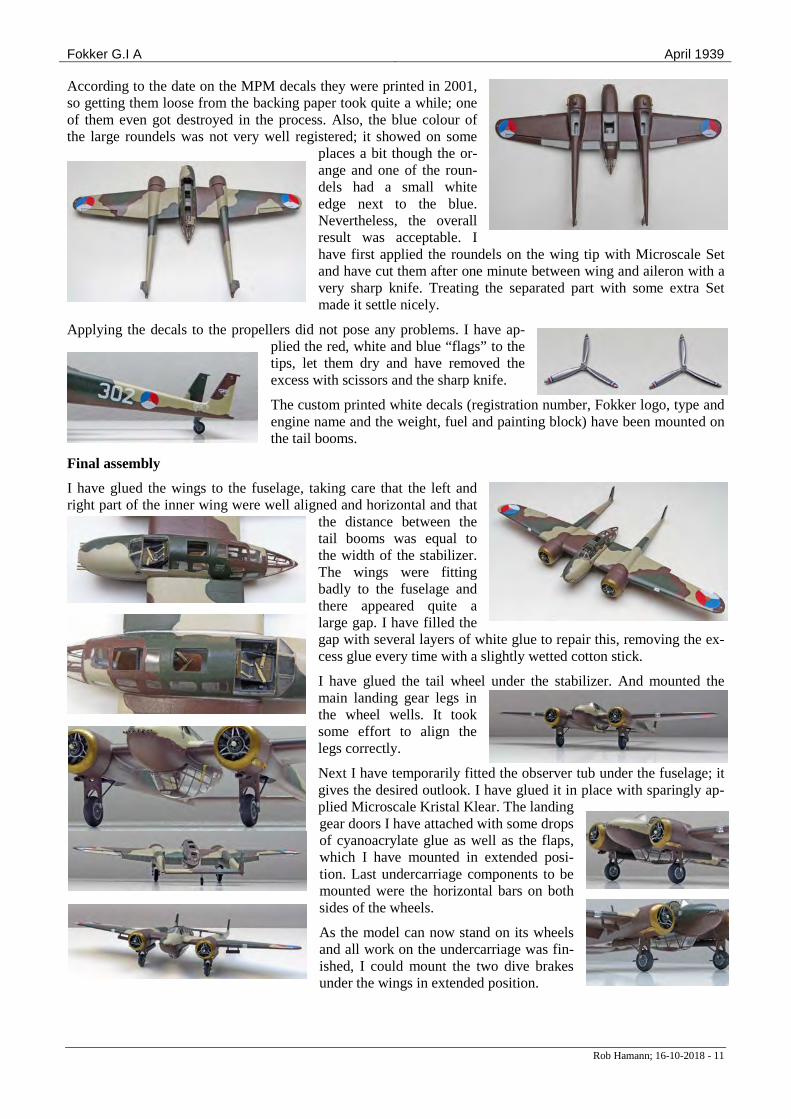
According to the date on the MPM decals they were printed in 2001, so getting them loose from the backing paper took quite a while; one of them even got destroyed in the process. Also, the blue colour of the large roundels was not very well registered; it showed on some
places a bit though the or-ange and one of the roun-dels had a small white edge next to the blue. Nevertheless, the overall result was acceptable. I have first applied the roundels on the wing tip with Microscale Set and have cut them after one minute between wing and aileron with a very sharp knife. Treating the separated part with some extra Set made it settle nicely.
Applying the decals to the propellers did not pose any problems. I have ap-plied the red, white and blue “flags” to the tips, let them dry and have removed the excess with scissors and the sharp knife.
The custom printed white decals (registration number, Fokker logo, type and engine name and the weight, fuel and painting block) have been mounted on the tail booms.
Final assembly
I have glued the wings to the fuselage, taking care that the left and right part of the inner wing were well aligned and horizontal and that
the distance between the tail booms was equal to the width of the stabilizer. The wings were fitting badly to the fuselage and there appeared quite a large gap. I have filled the gap with several layers of white glue to repair this, removing the ex-cess glue every time with a slightly wetted cotton stick.
I have glued the tail wheel under the stabilizer. And mounted the main landing gear legs in the wheel wells. It took some effort to align the legs correctly.
Next I have temporarily fitted the observer tub under the fuselage; it gives the desired outlook. I have glued it in place with sparingly ap-plied Microscale Kristal Klear. The landing gear doors I have attached with some drops of cyanoacrylate glue as well as the flaps, which I have mounted in extended posi-tion. Last undercarriage components to be mounted were the horizontal bars on both sides of the wheels.
As the model can now stand on its wheels and all work on the undercarriage was fin-ished, I could mount the two dive brakes under the wings in extended position.
Fokker G.I A April 1939
Rob Hamann; 16-10-2018 - 12
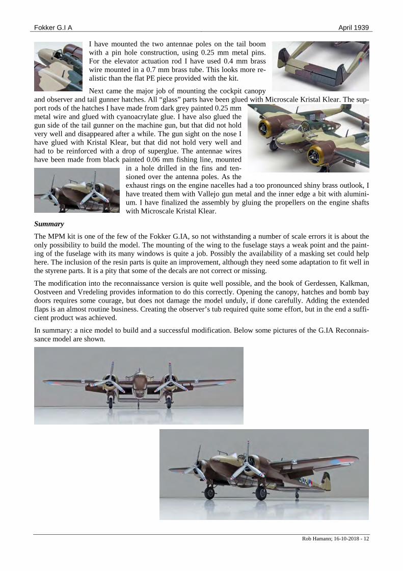
I have mounted the two antennae poles on the tail boom with a pin hole construction, using 0.25 mm metal pins. For the elevator actuation rod I have used 0.4 mm brass wire mounted in a 0.7 mm brass tube. This looks more re-alistic than the flat PE piece provided with the kit.
Next came the major job of mounting the cockpit canopy and observer and tail gunner hatches. All “glass” parts have been glued with Microscale Kristal Klear. The sup-port rods of the hatches I have made from dark grey painted 0.25 mm metal wire and glued with cyanoacrylate glue. I have also glued the gun side of the tail gunner on the machine gun, but that did not hold very well and disappeared after a while. The gun sight on the nose I have glued with Kristal Klear, but that did not hold very well and had to be reinforced with a drop of superglue. The antennae wires have been made from black painted 0.06 mm fishing line, mounted
in a hole drilled in the fins and ten-sioned over the antenna poles. As the exhaust rings on the engine nacelles had a too pronounced shiny brass outlook, I have treated them with Vallejo gun metal and the inner edge a bit with alumini-um. I have finalized the assembly by gluing the propellers on the engine shafts with Microscale Kristal Klear.
Summary
The MPM kit is one of the few of the Fokker G.IA, so not withstanding a number of scale errors it is about the only possibility to build the model. The mounting of the wing to the fuselage stays a weak point and the paint-ing of the fuselage with its many windows is quite a job. Possibly the availability of a masking set could help here. The inclusion of the resin parts is quite an improvement, although they need some adaptation to fit well in the styrene parts. It is a pity that some of the decals are not correct or missing.
The modification into the reconnaissance version is quite well possible, and the book of Gerdessen, Kalkman, Oostveen and Vredeling provides information to do this correctly. Opening the canopy, hatches and bomb bay doors requires some courage, but does not damage the model unduly, if done carefully. Adding the extended flaps is an almost routine business. Creating the observer’s tub required quite some effort, but in the end a suffi-cient product was achieved.
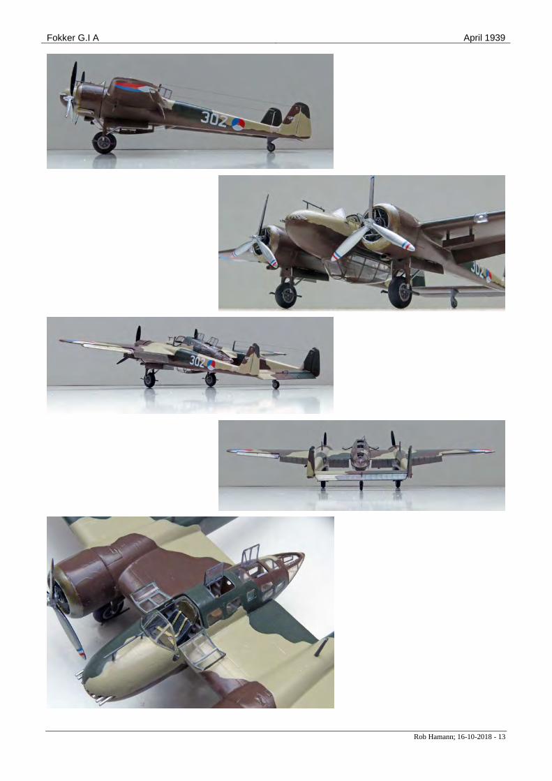
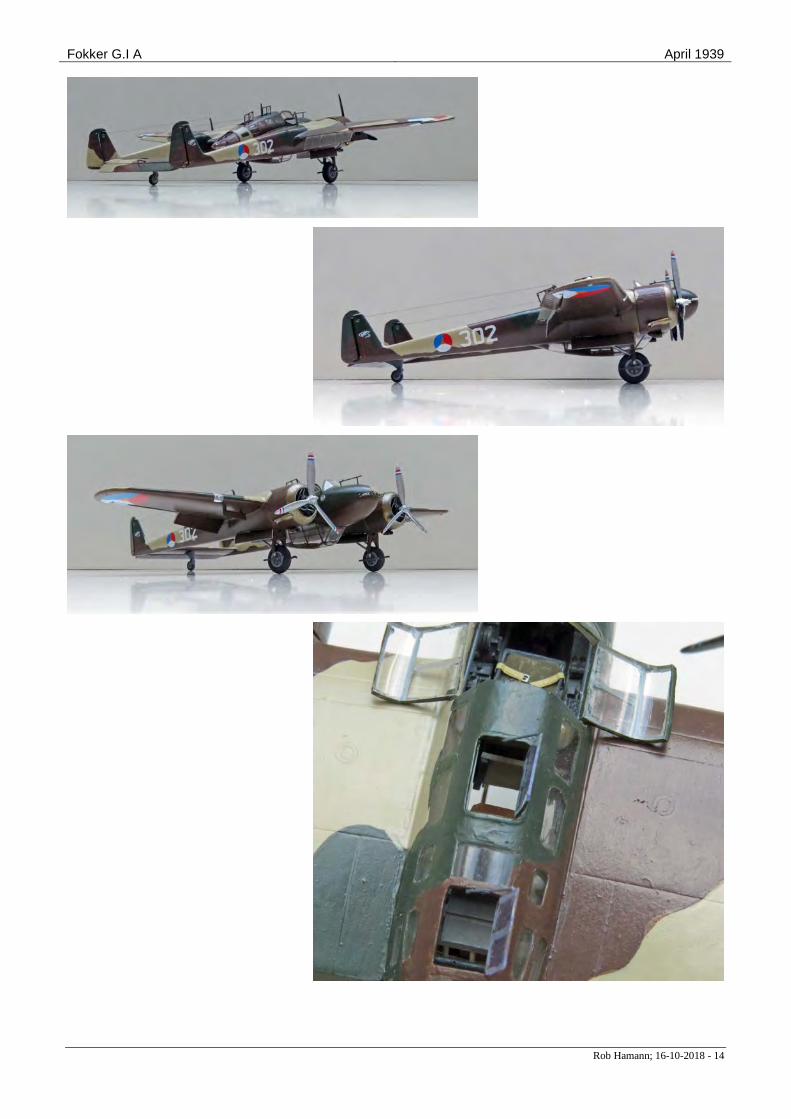
In summary: a nice model to build and a successful modification. Below some pictures of the G.IA Reconnais-sance model are shown.
Fokker G.I A April 1939
Rob Hamann; 16-10-2018 - 13
Fokker G.I A April 1939
Rob Hamann; 16-10-2018 - 14
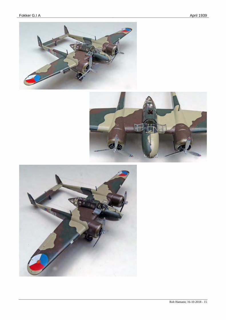
Fokker G.I A April 1939
Rob Hamann; 16-10-2018 - 15
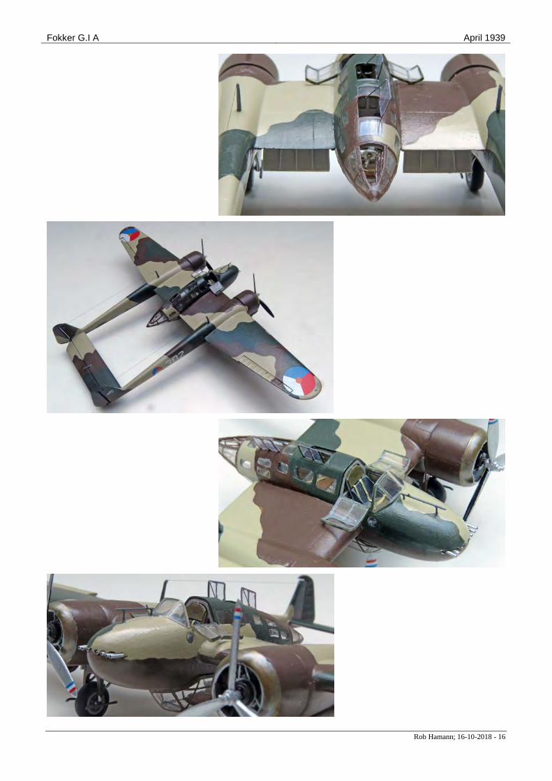
Fokker G.I A April 1939
Rob Hamann; 16-10-2018 - 16
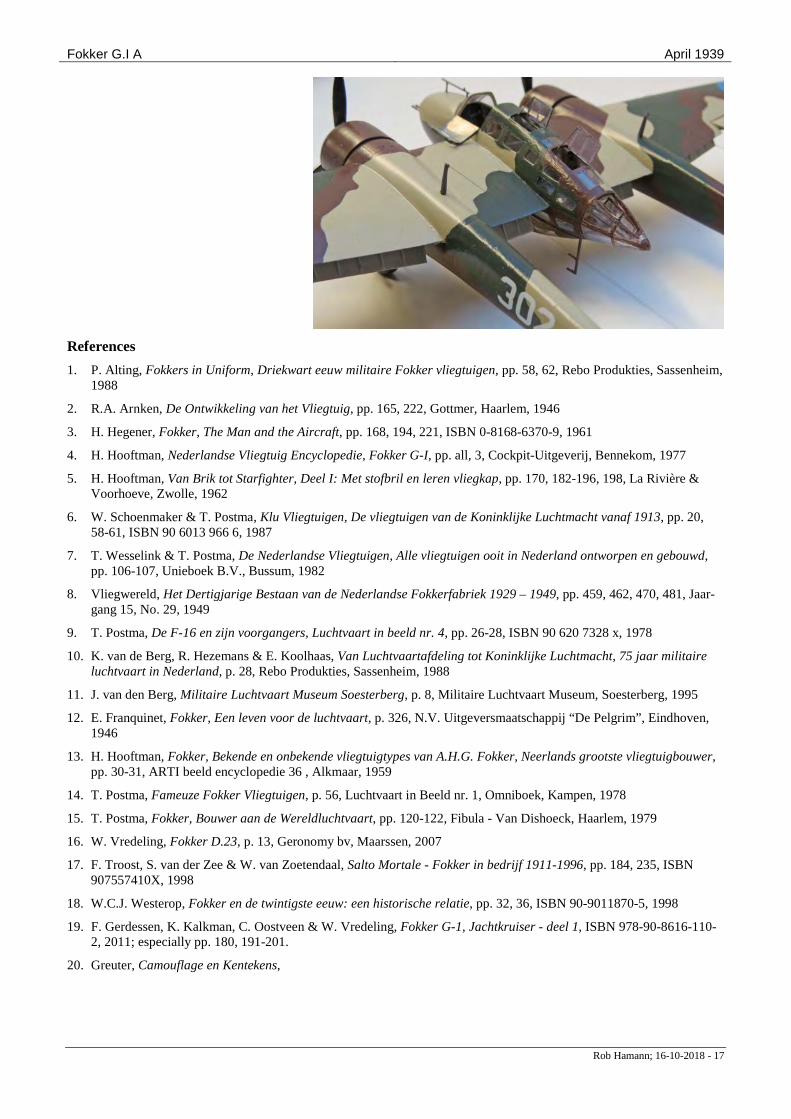
Fokker G.I A April 1939
Rob Hamann; 16-10-2018 - 17
References 1. P. Alting, Fokkers in Uniform, Driekwart eeuw militaire Fokker vliegtuigen, pp. 58, 62, Rebo Produkties, Sassenheim,
1988
2. R.A. Arnken, De Ontwikkeling van het Vliegtuig, pp. 165, 222, Gottmer, Haarlem, 1946
3. H. Hegener, Fokker, The Man and the Aircraft, pp. 168, 194, 221, ISBN 0-8168-6370-9, 1961
4. H. Hooftman, Nederlandse Vliegtuig Encyclopedie, Fokker G-I, pp. all, 3, Cockpit-Uitgeverij, Bennekom, 1977
5. H. Hooftman, Van Brik tot Starfighter, Deel I: Met stofbril en leren vliegkap, pp. 170, 182-196, 198, La Rivière & Voorhoeve, Zwolle, 1962
6. W. Schoenmaker & T. Postma, Klu Vliegtuigen, De vliegtuigen van de Koninklijke Luchtmacht vanaf 1913, pp. 20, 58-61, ISBN 90 6013 966 6, 1987
7. T. Wesselink & T. Postma, De Nederlandse Vliegtuigen, Alle vliegtuigen ooit in Nederland ontworpen en gebouwd, pp. 106-107, Unieboek B.V., Bussum, 1982
8. Vliegwereld, Het Dertigjarige Bestaan van de Nederlandse Fokkerfabriek 1929 – 1949, pp. 459, 462, 470, 481, Jaar-gang 15, No. 29, 1949
9. T. Postma, De F-16 en zijn voorgangers, Luchtvaart in beeld nr. 4, pp. 26-28, ISBN 90 620 7328 x, 1978
10. K. van de Berg, R. Hezemans & E. Koolhaas, Van Luchtvaartafdeling tot Koninklijke Luchtmacht, 75 jaar militaire luchtvaart in Nederland, p. 28, Rebo Produkties, Sassenheim, 1988
11. J. van den Berg, Militaire Luchtvaart Museum Soesterberg, p. 8, Militaire Luchtvaart Museum, Soesterberg, 1995
12. E. Franquinet, Fokker, Een leven voor de luchtvaart, p. 326, N.V. Uitgeversmaatschappij “De Pelgrim”, Eindhoven, 1946
13. H. Hooftman, Fokker, Bekende en onbekende vliegtuigtypes van A.H.G. Fokker, Neerlands grootste vliegtuigbouwer, pp. 30-31, ARTI beeld encyclopedie 36 , Alkmaar, 1959
14. T. Postma, Fameuze Fokker Vliegtuigen, p. 56, Luchtvaart in Beeld nr. 1, Omniboek, Kampen, 1978
15. T. Postma, Fokker, Bouwer aan de Wereldluchtvaart, pp. 120-122, Fibula - Van Dishoeck, Haarlem, 1979
16. W. Vredeling, Fokker D.23, p. 13, Geronomy bv, Maarssen, 2007
17. F. Troost, S. van der Zee & W. van Zoetendaal, Salto Mortale - Fokker in bedrijf 1911-1996, pp. 184, 235, ISBN 907557410X, 1998
18. W.C.J. Westerop, Fokker en de twintigste eeuw: een historische relatie, pp. 32, 36, ISBN 90-9011870-5, 1998 19. F. Gerdessen, K. Kalkman, C. Oostveen & W. Vredeling, Fokker G-1, Jachtkruiser - deel 1, ISBN 978-90-8616-110-
2, 2011; especially pp. 180, 191-201. 20. Greuter, Camouflage en Kentekens,
Fokker G.I A April 1939
Rob Hamann; 16-10-2018 - 18
Appendix Model modifications and corrections; pictures, drawings and other documentation of the Fokker F.VIII Modifications & corrections M = modification, C = correction Change Location/part Modification or correction M01 Cockpit Side windows opened up C01 Cockpit Forward wing spar introduced,
side consoles shortened, oxygen bottle relocated
C02 Cockpit Roll bar and pilot seat backing M02 Control sur-
faces Deflected configuration
M03 Engine Valve rod covers M04 Fuselage Vacform observer’s tub canopy M05 Fuselage Radio operator and tail gunner
hatches opened up; new hatches C03 Fuselage Tail gunner hatch enlarged M06 Fuselage Radio-operator compartment floor
and hatch M07 Fuselage Observer folding seat M08 Fuselage Tail gun window opened up; new
windows M09 Undercarriage Wheel axles M10 Wing Diving brakes C04 Wing Landing flap edges M11 Wing Landing flaps
Paint table H = Humbrol, R = Revell, V = Vallejo, WEM = White Ensign Models Code Colour Where H2 Green Oxygen bottles H21 Black Cylinders (base), crank case H33 Black (matt) Rear side of propellers H62 Leather Observer & tail gunner seats H103 Cream Seat belts H113 Rust Exhausts (dry brushed) H117 US green Pilot seat cushions H129 Light grey Interior walls, wheel hubs H164 Dark grey Instrument panels, wheel
spokes, fuselage frame tubes H1325 Transparent
green Navigation lights
R731 Transparent red Navigation lights R36178 Tank grey Tires V71.062 Aluminium Front side of propellers, seat
belt buckles, landing lights, inside ring of exhaust rings
V71.065 Steel Cylinders (dry brush) V71.067 Bright brass Cowling front, exhausts V71.072 Gun metal Machine guns, exhaust rings
(dry brush) V71.073 Black metallic Machine guns (dry brush) WEM ACD01
LVA camou-flage green; FS24077
Upper surfaces
WEM ACD02
LVA camou-flage brown; FS20059
Upper and lower surfaces
WEM ACD03
LVA camou-flage light sand; FS26360
Upper surfaces
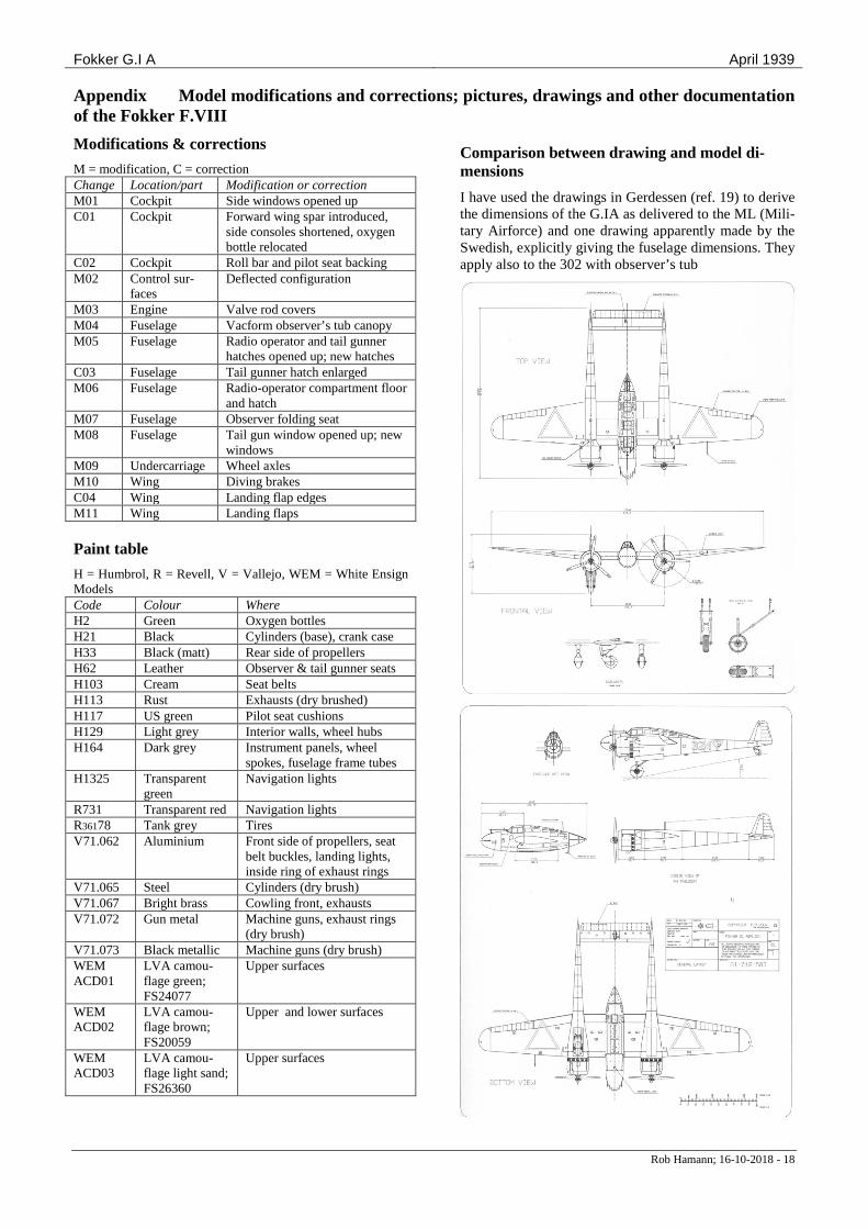
Comparison between drawing and model di-mensions I have used the drawings in Gerdessen (ref. 19) to derive the dimensions of the G.IA as delivered to the ML (Mili-tary Airforce) and one drawing apparently made by the Swedish, explicitly giving the fuselage dimensions. They apply also to the 302 with observer’s tub
Fokker G.I A April 1939
Rob Hamann; 16-10-2018 - 19
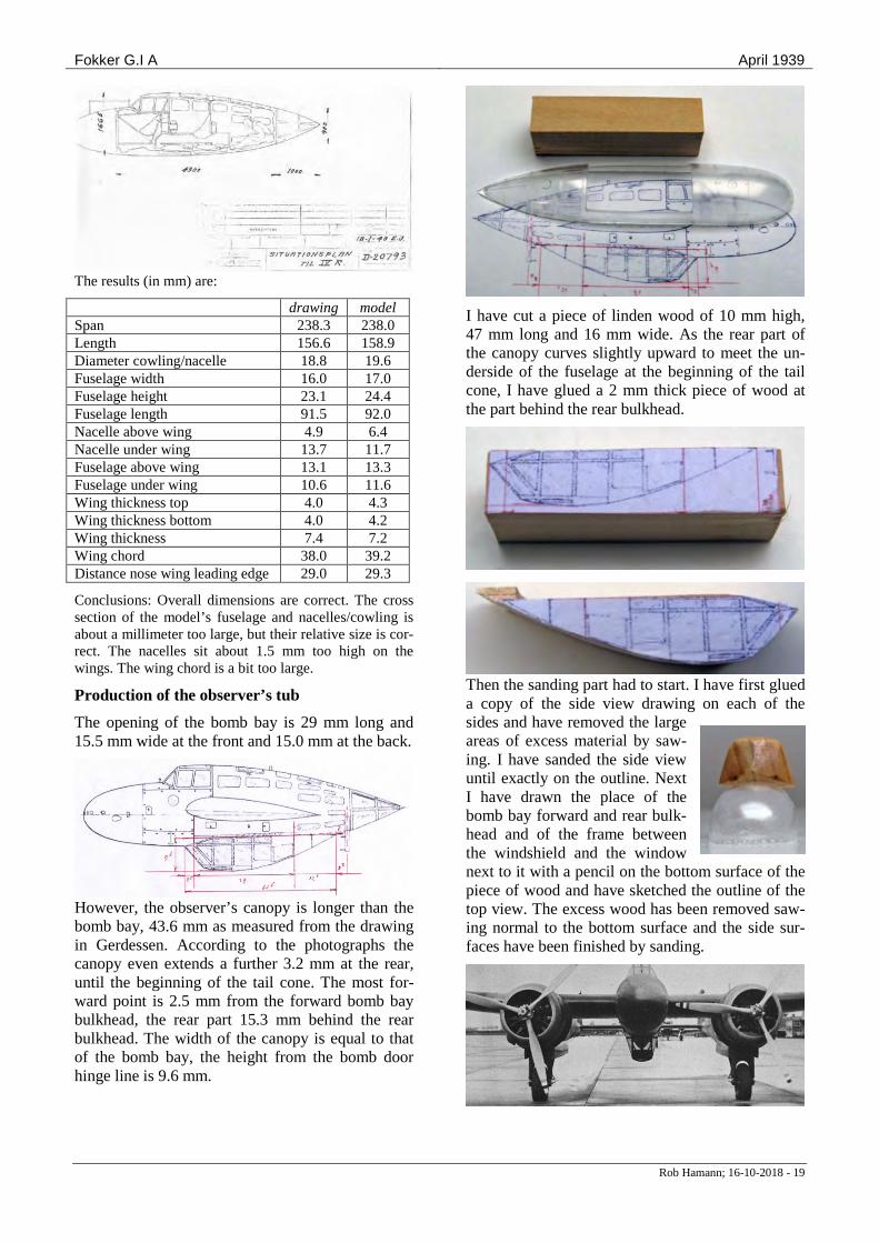
The results (in mm) are:
drawing model Span 238.3 238.0 Length 156.6 158.9 Diameter cowling/nacelle 18.8 19.6 Fuselage width 16.0 17.0 Fuselage height 23.1 24.4 Fuselage length 91.5 92.0 Nacelle above wing 4.9 6.4 Nacelle under wing 13.7 11.7 Fuselage above wing 13.1 13.3 Fuselage under wing 10.6 11.6 Wing thickness top 4.0 4.3 Wing thickness bottom 4.0 4.2 Wing thickness 7.4 7.2 Wing chord 38.0 39.2 Distance nose wing leading edge 29.0 29.3
Conclusions: Overall dimensions are correct. The cross section of the model’s fuselage and nacelles/cowling is about a millimeter too large, but their relative size is cor-rect. The nacelles sit about 1.5 mm too high on the wings. The wing chord is a bit too large.
Production of the observer’s tub
The opening of the bomb bay is 29 mm long and 15.5 mm wide at the front and 15.0 mm at the back.
However, the observer’s canopy is longer than the bomb bay, 43.6 mm as measured from the drawing in Gerdessen. According to the photographs the canopy even extends a further 3.2 mm at the rear, until the beginning of the tail cone. The most for-ward point is 2.5 mm from the forward bomb bay bulkhead, the rear part 15.3 mm behind the rear bulkhead. The width of the canopy is equal to that of the bomb bay, the height from the bomb door hinge line is 9.6 mm.
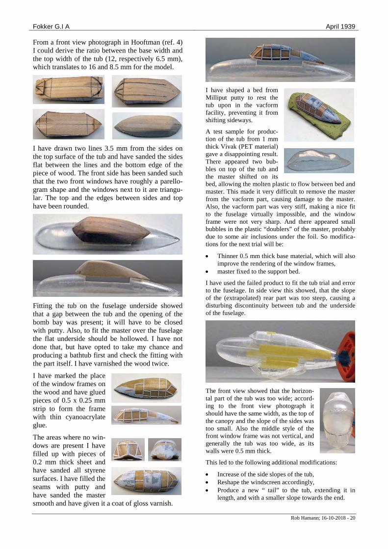
I have cut a piece of linden wood of 10 mm high, 47 mm long and 16 mm wide. As the rear part of the canopy curves slightly upward to meet the un-derside of the fuselage at the beginning of the tail cone, I have glued a 2 mm thick piece of wood at the part behind the rear bulkhead.
Then the sanding part had to start. I have first glued a copy of the side view drawing on each of the sides and have removed the large areas of excess material by saw-ing. I have sanded the side view until exactly on the outline. Next I have drawn the place of the bomb bay forward and rear bulk-head and of the frame between the windshield and the window next to it with a pencil on the bottom surface of the piece of wood and have sketched the outline of the top view. The excess wood has been removed saw-ing normal to the bottom surface and the side sur-faces have been finished by sanding.
Fokker G.I A April 1939
Rob Hamann; 16-10-2018 - 20
From a front view photograph in Hooftman (ref. 4) I could derive the ratio between the base width and the top width of the tub (12, respectively 6.5 mm), which translates to 16 and 8.5 mm for the model.
I have drawn two lines 3.5 mm from the sides on the top surface of the tub and have sanded the sides flat between the lines and the bottom edge of the piece of wood. The front side has been sanded such that the two front windows have roughly a parello-gram shape and the windows next to it are triangu-lar. The top and the edges between sides and top have been rounded.
Fitting the tub on the fuselage underside showed that a gap between the tub and the opening of the bomb bay was present; it will have to be closed with putty. Also, to fit the master over the fuselage the flat underside should be hollowed. I have not done that, but have opted to take my chance and producing a bathtub first and check the fitting with the part itself. I have varnished the wood twice.
I have marked the place of the window frames on the wood and have glued pieces of 0.5 x 0.25 mm strip to form the frame with thin cyanoacrylate glue.
The areas where no win-dows are present I have filled up with pieces of 0.2 mm thick sheet and have sanded all styrene surfaces. I have filled the seams with putty and have sanded the master smooth and have given it a coat of gloss varnish.
I have shaped a bed from Milliput putty to rest the tub upon in the vacform facility, preventing it from shifting sideways.
A test sample for produc-tion of the tub from 1 mm thick Vivak (PET material) gave a disappointing result. There appeared two bub-bles on top of the tub and the master shifted on its bed, allowing the molten plastic to flow between bed and master. This made it very difficult to remove the master from the vacform part, causing damage to the master. Also, the vacform part was very stiff, making a nice fit to the fuselage virtually impossible, and the window frame were not very sharp. And there appeared small bubbles in the plastic “doublers” of the master, probably due to some air inclusions under the foil. So modifica-tions for the next trial will be:
• Thinner 0.5 mm thick base material, which will also improve the rendering of the window frames,
• master fixed to the support bed.
I have used the failed product to fit the tub trial and error to the fuselage. In side view this showed, that the slope of the (extrapolated) rear part was too steep, causing a disturbing discontinuity between tub and the underside of the fuselage.
The front view showed that the horizon-tal part of the tub was too wide; accord-ing to the front view photograph it should have the same width, as the top of the canopy and the slope of the sides was too small. Also the middle style of the front window frame was not vertical, and generally the tub was too wide, as its walls were 0.5 mm thick.
This led to the following additional modifications:
• Increase of the side slopes of the tub, • Reshape the windscreen accordingly, • Produce a new “ tail” to the tub, extending it in
length, and with a smaller slope towards the end.
Fokker G.I A April 1939
Rob Hamann; 16-10-2018 - 21
First step was to correct the fit of the tub to the fuselage. I have cut the forward part from the lower fuselage half and have fitted the old master on it after removing quite some ma-terial from the sides to reduce the width of the top windows.
The picture above shows very clearly the wrong fitting of the tub to the fuselage. I have used Milliput putty to roughly shape the rear part of the tub until the beginning of the tail cone.
When that had set, I have gradually sanded the rear part of the tub in shape, first by adjusting the cross section to the slope of the side windows, then by making a smooth transition from tub to fuselage. I have decided to use the transparent fuselage as an integral part of the master, so I have filled it up with Albastine putty and have “re-paired” the missing parts with Tamyia putty.
After a coat of gloss varnish I have made the frame from narrow strips of 0.1 mm thick aluminium tape.
I have fitted the upper half of the fuselage on it and have adjusted the lower windshield frame such that it fitted the lower nose section well. Again the whole surface has been given a coat of clear varnish to fix the tape in place.
I have made a box from 1.5 mm plastic sheet and have glued the master temporari-ly to the bottom of the box and have produced the sili-cone mould. The master could be easily removed from the mould and the frame details had been re-produced quite well.
Next I have filled the mould with resin. After setting, I have removed the tub from the mould. It needed only very little rework.
The resin part has been cured for several hours in warm water of 60 C, and has served as master for the vacform observers tub.
I have made the vacform copies with a small vacform machine, apparently also used by den-tists. The blue top contains the heating element, the brass but-ton serves to clamp the sheet in the grey metal coloured frame it is attached, and the blue bottom compartment contains the fan, which makes the noise of a jet engine, when actuated. The frame can be moved up and down with the handle at the
Fokker G.I A April 1939
Rob Hamann; 16-10-2018 - 22
right. The procedure is quite simple: Clamp a 12.5 x 12.5 mm plastic sheet in the frame, secure the frame with the brass knob, move the frame in top position, switch on the heating element (right button), observe the sheet and flip the handle when the sheet starts to hang down, bringing the frame with the sheet over the masters and at the same time switching on the fan (left button), and switch the heating element off. Switch off the terrible noise. After cooling down the vacform part can be re-moved and cut to size.
The first copy I have made from 0.5 mm thick Vivak plastic (left on the picture). This worked well, but was rather stiff, so I made a second copy (right on the pic-
ture) from plastic report cover sheet I normally use to make windows. This came also out quite well, even when the thin sheet slipped from the clamping frame.
After cutting the tub from the plastic sheet the windows showed quite some small ir-
regularities; the surface faithfully reproduced the varnish brush strokes and other irregularities present in the resin master.
Adjusting it bit by bit to fit the lower fuselage half showed that dimensionally it was correct, although for the Vivak copy the lower edges needed quite some rework to fit smoothly on the fuselage sides. From that point of view the second copy was quite a bit easier to fit due to its flexibility.
Remained the problem of “clearing” the windows. I have decided to sand and polish the inner tub surface in an attempt to remove the irregularities. This was only pos-sible with the Vivak copy, the thinner copy being too flexible and thin too handle.
After some sanding the inner surfaces most windows showed up nicely grey, meaning that the damage had been removed. On some places spots remained, of which a number could also be observed at the outer surface.
Before continuing the sanding exercise I have decided to polish the surface, because that was the only way to see the window quality clearly.
This worked only partially; the windows stayed rather opaque, leading to an unacceptable result.
After sanding and applying putty to the master another time I have sprayed it with can paint. The surface air bubbles had disappeared almost completely, while leav-ing the window frame lines still a bit visible, and it was worthwhile to give the vacuum machine another try.
As the Vivak copies appeared to be rather stiff, which would make the observers tub difficult to adjust to the fuselage underside, I experimented this time with plas-tics of different thickness and composition:
• 0.2 mm thick report cover sheet • 0.3 mm thick report cover sheet • 0.5 mm thick Vivak (PET).
The 0.2 mm sheet did not clamp well in the machine and as a result did not form at all. The 0.3 mm gave a good result and seemed to have an appropriate flexibility4.
Although the plastic has a slight blue hue, this does not show up in the copy.
Fokker G.I A April 1939
Rob Hamann; 16-10-2018 - 23
I have removed the tub from the plastic and have adjust-ed it bit by bit to fit well centered under the fuselage.
Documents, photographs and drawings If no source is mentioned, the documents have been tak-en from the Internet.
[Source: Gerdessen, ref.19; note that the final version has the dimensions of the version drawn at the top and a window ar-rangement ressembling the version at the bottom]
[Source: Gerdessen, ref.19]
[Source: Gerdessen, ref.19]
[Source: Gerdessen, ref.19]
[Source: Gerdessen, ref.19]
[Source: Gerdessen, ref.19]
[Source: Gerdessen, ref.19]
Fokker G.I A April 1939
Rob Hamann; 16-10-2018 - 24
[Source: Hooftman, ref.4]
[Source: Hooftman, ref.4]
[Source: Gerdessen, ref.19]
[Source: Gerdessen, ref.19]
[Source: Gerdessen, ref.19]
[Source: Gerdessen, ref.19]
[Source: Gerdessen, ref.19]
[Source: Gerdessen, ref.19]
Fokker G.I A April 1939
Rob Hamann; 16-10-2018 - 25
[Source: Gerdessen, ref.19]
[Source: Gerdessen, ref.19]
[Source: Gerdessen, ref.19]
[Source: Fokker Calendar]
1 www.mpmshop.eu 2 I do not know the exact contents of this criticism. I have included a comparison of the model’s dimensions and the dimensions derived from the drawings in ref. 19 in the appendix. 3 Initially I made the mistake to saw the cylinders off at the base of the wider part instead of at the side of the resin bar and I even could not make them fit at all in the crankcase. Fortunately I had a full spare set (bought to replace the cracked top part of the fuselage) to compensate for the waste. 4 I did not try the Vivak here, but in the same session used it to produce a canopy for another project.


![General Subjects Section ADVANCED INFANTRY Q]'FICERS … · 30 bomber reconnaissance planes and 100 single engine fighters ... 242nd Fussiliare Battalion ... In order to orient the](https://img.dokumen.tips/doc/110x75/5ceaeebf88c9931e1e8d9753/general-subjects-section-advanced-infantry-qficers-30-bomber-reconnaissance.jpg)
![G.3 (Military aircraft) G.IV (Bomber) G5 automobile · G.III (Bomber) USEFriedrichshafen G.III (Bomber) G.IV (Bomber) USEAEG G.IV (Bomber) G-machine (Computer) (Not Subd Geog) [QA76.8.G]](https://img.dokumen.tips/doc/110x75/5f09a0207e708231d427bb82/g3-military-aircraft-giv-bomber-g5-automobile-giii-bomber-usefriedrichshafen.jpg)