Embed Size (px)
DESCRIPTION
GRAPH
Citation preview

Chapter 7
DISTRIBUTION AND USE
In many rural areas, wells equipped with hand pumps and conveniently located are used as sources of domestic water-supply for individual houses and villages. Since the water obtained in this way must be carried in cans or buckets from the wells to the houses, the amount of water is usually limited and too small for the effective promotion of health and personal hygiene. Although the use of wells in villages is inevitable and often dictated by economic and engineering considerations, the distribution of water from a central source by means of pipes to each village house is a goal towards which every community should strive, because of its obvious advantages. The most important benefits are convenience and an increased supply which may be made, at the same time, wholesome and safe for the protection of health.
Water-distribution systems for rural areas are essentially similar to those of urban communities. Often it is possible for the sake of economy to group a number of villages relatively close to each other and to supply them from a central water source. The difference between rural and urban water-distribution systems is to be found in the standards and assumptions upon which engineering designs are based. While not compromising on essential water quality standards, such differences include the amounts of water for domestic consumption, the standards of protection against fire, and the degree of water treatment.
The design of a rural water-distribution system involves : (I) the deter- mination of storage; (2) the location and size of feeders; (3) the location and sizes of distribution pipes, valves, and hydrants; and (4) the determi- nation of the pressure required in the system. Before the design is under- taken, it is necessary to make a reconnaissance survey of the village and of the area leading to the source of supply. Often such a survey, carried out by a trained engineer, will be sufficient to enable him to decide on the route to be followed by the feeder pipe and on the location of distributing reservoirs and main pipes. This reconnaissance should be followed by a topographic survey in order to determine the locations and elevations of street intersections; of all low and high points within the village; of streams, gullies, depressions or similar topographical features which may bear upon the design; and, finally, of the feeder line and the distributing reservoir.
INSTALLATION OF WATER-SUPPLY SYSTEMS 195
When the construction of the distribution system is completed, similar maps should be prepared for future reference showing the exact location of all pipes, reservoirs, valves, hydrants, and other appurtenances.
Small-Community Distribution Systems
Distributing reservoir
In small distribution systems, whether the water is obtained by gravity or by pumping, it is always desirable to provide a distribution reservoir. The main reasons are :
(1) the need to satisfy hourly variations in the rate of consumption (in small systems, such variations may be three times the average hourly consumption and sometimes more);
(2) the desirability of maintaining adequate pressure throughout the distribution system;
(3) the possibility of repairing adduction pipes between the source of supply and the reservoir, without interruption of the village water service.
(4) The need to provide for fire protection. Other advantages which, under certain circumstances, may assume
considerable economic importance include the following : (1) Where the water is pumped to the reservoir, pumps can be operated
uniformly throughout the day. Such pumps may be much smaller than would be required otherwise.
(2) With such a reservoir, the size of the adduction pipe between the supply source and the reservoir can be made smaller than would be necessary if the village were fed directly from the water source.
In most small rural schemes no special arrangements are made for fire protection. Notes on fire services are included on pages 203-205, 206, 239 but the paragraphs preceding these are based on the assumption that no provision for fire hydrants is being made.
The first consideration when designing storage is the capacity which will be provided. This to a great extent depends on the type of supply, and is influenced by two main factors-the necessity of catering for peak demand periods, and the provision of reserve to cover normal breakdown or main- tenance interruptions.
Conditions vary in different parts of the world, but a typical pattern of draw-off in a village is as follows-30% of the day's supply between 7 a.m. and 8 a.m.; 30% between 5 p.m. and 6.30 p.m.; 35 %during the other hours of daylight; and 5% between sunset and sunrise. Local customs will produce local variations; for instance, in Moslem countries the demand during Ramadan will be high at about 3 a.m., and in other parts of the world where Monday is the traditional " wash-day " the Monday morning

196 WATER SUPPLY FOR R U R A L AREAS
draw-off may be equivalent to the total supply of another day. These and similar considerations must be taken into account when assessing the extent and duration of peak draw-offs : this must then be balanced against the rate and periods of water delivery.
When water is supplied by gravity from the source it is most economical in capital cost, as well as most satisfactory from an operational aspect, if a constant flow is maintained throughout the twenty-four hours. Obviously in such a method of working a smaller delivery main is needed than if larger quantities are required in shorter periods. When electricity is used for pumping it is usually most economical to operate for about twenty hours a day, leaving the pumps idle during the peak hours of electricity demand. With diesel- or petrol-driven pumps, the cost of attendance (necessarily continuous with such engines, but normally unnecessary with electric motors) becomes an important factor, and one shift of eight hours, or two totalling 16 hours, is a frequent method of operation. It is quite common to find schemes designed to operate with a single shift of 8 hours initially, increasing to 16 hours when the demand rises later. More than 16 hours a day is not desirable with such engines; not only do Labour costs increase but the wear on machinery working continuously throughout the day and night becomes excessive and the life of the plant is correspondingly shortened.
Once the probable distribution of draw-off during the 24 hours and the proposed hours of delivery is decided, two graphs can be drawn, similar to diagrams A and B in Fig. 72. In this case a probable demand of 136000 litres per day is envisaged, to be provided by pumping for eight hours per day between 8 a.m. and 4 p.m. These graphs are then superimposed, as at diagram C, in such a way that the lowest point on line B touches, but does not come below, line A. This gives a theoretical picture of how much
Town requiring 136000 litres per day, wi th low draw-off at night and peak periods 7 a.m. t o 8 a.m. and 5 p.m. t o 6.30 p.m.
Graph A - shows consumption throughout the day; steep slopes show peak hours.
Graph B - shows pumping between 8 a.m. and 4 p.m. 136 001 litres in 8 hours equals 17 000 litres per hour.
Graph C - shows graphs A and B combined. The vertical distance between the t w o lines represents the reservoir capacity required at any time, the maximum distance occurring at 4 p.m. and representing 102000 litres required. Reservoir assumed t o be empty at 8 a.m.
Graph D - shows the effect on reservoir capacity required i f pumping hours are changed t o from 5.30 a.m. t o 1.30 p.m. Maximum distance now occurs at 1.30 p.m. and represents 70000 litres required. Reservoir empty at 5.30 a.m. and again at 8.00 a.m.
Graph E -shows the same consumption pattern as Graph A but wi th continuous supply throughout 24 hours by gravity main at 1250 gals. per hour. Maximum reservoir capacity now required at 7 a.m. equals 57 000 litres. Reservoir empties completely at 6.30 p.m. and starts refilling immediately as supply exceeds draw-off from that t ime on.

INSTALLATION OF WATER-SUPPLY SYSTEMS 197
Fig. 72. DlSTRlBUTlON RESERVOIRS: THEORETICAL RESERVOIR CAPACITY REQUIRED
50000 I.
Hour 8 Noon 16
Noon I Hour 5:30 13:30
150000 1.
100000 I.
50000 1 . -
150000 I. -
100000 I . -
E z , I _ - U , i , ' ' '
Hour 0 1 2 3 4 5 6 7 8 7 11) 1 1 12 13 14 15 16 17 18 17 20 21 22 23 24
-
-
- Hour 8 Noon 16

198 WATER SUPPLY FOR RURAL AREAS
storage will be required, the vertical distance between the two lines represent- ing the amount in the reservoir at any hour of the day.
From this example the reservoir would be empty at 8 a.m., filling to a maximum of 102 000 litres at 4 p.m., and thence emptying at varying rates until 8 a.m. the next day when pumping starts again.
It can be seen that the hours of pumping proposed are uneconomical in this instance, and diagram D shows how the storage required is decreased by arranging the pumping hours between 5.30 a.m. and 1.30 p.m., the max- imum difference between supply and demand now being 70 000 litres at 1.30 p.m.
Diagram E assumes that instead of pumping, the water is supplied by a gravity main from source, running through the day and night at 5665 litres per hour. In this case the highest storage demand occurs at 7 a.m., and 57 000 litres' reserve is needed, the reservoir emptying at 6.30 p.m.
The figures obtained by the above method show the minimum storage required to satisfy hourly variation in flow; they take no account of break- down or repairs, and it is necessary to add to the reservoir capacity for these contingencies. The quantity required for this purpose will depend on the layout of the installation.
Provided that adequate standby pumping plant has been provided and can be brought into use immediately as, for example, if the supply is from duplicate bore-holes each capable of supplying full needs) little need be added for repair purposes, but the problem of a burst main must always be taken into account, and the time taken in repairing such a main must depend on the local facilities available. In a typical rural scheme it is usual to allow 8 hours at the time of day with the highest flow, and to rely on pumping extra hours to make up those lost.
In the instance illustrated, then, an extra 70 800 litres would be provided, assuming that a burst might occur at 7 a.m., and this, added to the require- ments calculated from diagram D, would suggest a storage reservoir of 140 800 litres. If the supply were from a gravity main, as in diagram E, the reservoir would be calculated on the basis of 127 800 litres.
It will be seen that in both these instances the storage required is in the neighbourhood of a day's supply, and in cases where conditions are not sufficiently well known for accurate calculations to be made it is usual, as a rule-of-thumb method, to work on one day's supply as the storage required. In no case should such storage be less than half a day's supply.
There are conditions under which much larger storage should be pro- vided, e.g., where pumping is by electricity of which the supply is outside the control of the water authority and which may go out of action for long periods. In such cases it is usual to be pessimistic and to allow for consi- derable periods of interruption.
Once the size of the reservoir required has been arrived at, the next consideration is its site, and one of the most important points influencing

INSTALLATION OF WATER-SUPPLY SYSTEMS 199
this choice is the question of levels. It is necessary that the bottom water level shall be at such a height that, allowing for friction loss in the dis- tribution mains, a residual head of about 10 metres (33 feet) for single- storey buildings is obtained in any part of the system. This can be ensured either by siting the reservoir on high ground or by building on a tower. Since the cost of an elevated tank is much more expensive than of one built on the ground, the first choice of site will nearly always be high ground if there is any within a suitable distance from the town.
Assuming, however, that the site is flat and that an elevated tank is required, it is usual to construct this tank in a position which is relatively central to the distribution (thus avoiding long, and consequently large- diameter, service mains), and which has a tendency toward the pumping station rather than away from it so as to keep the friction in the pumping main to a minimum.
Wherever it is possible to avoid it, no distribution mains or connexions should be taken directly from the rising main, and all water should be pump- ed in the first instance to the tank directly. This is particularly important when centrifugal pumps with steep efficiency curves are used as they can pump at all times at a maximum efficiency if the head does not fluctuate with the demand.
Other advantages of direct pumping are : the ability to close down parts of the distribution system without interfering with the rest of the town, and to check consumption by observing the draw-off from the tank, the increased contact period when chlorine is used as a sterilizing agent, and the maintenance of a much more constant pressure in all services. Leak detection, too, is simpler when individual parts of the system can be shut off or metered separately, as is not possible when pumping is done into the distribution system.
There are, however, occasions when a combined rising and distribution main are desirable, particularly when of necessity the reservoir is at the opposite end of the town from the pumping plant so that for direct pumping a long rising main would have to be laid parallel to a service main, with consequent duplication of costs. With a pump of very flexible performance, such as a reciprocating pump, a saving in fuel results if all the water does not have to be pumped to a high-level reservoir, but is drawn off en route a t a lower head.
Ground-level reservoirs are usually built of masonry, mass concrete or reinforced concrete according to the materials and local skills available Reinforced concrete is most economical in cement (which is, in most cases, the most expensive of the materials used, particularly in rural areas where long transport hauls are involved) but on the other hand it needs steel, timber for forms, and skilled supervision. Masonry is usually cheaper than mass concrete where suitable stone is available, as the aggregate does not have to be broken and graded to the same extent, and forms are unnecessary,
WATER SUPPLY FOR RURAL AREAS
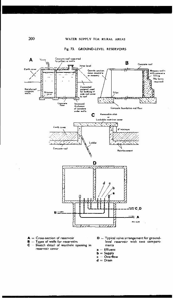
Fig. 73. GROUND-LEVEL RESERVOIRS
A vents Concrete root supported
of concrete Concrete foundation and floor under walls
C Removable slob or
Lockable cost-iron cover
A = Cross-section of reservoir D = Typical valve arrangement for ground- B = Types of walls for reservoirs level reservoir with two compart- C = Sketch detail of manhole opening in rnents
reservoir cover a = Effluent b = Supply c = Overflow d = Drain

INSTALLATION OF WATER-SUPPLY SYSTEMS 20 1
but it is more difficult to make watertight. A compromise between masonry and mass concrete is often employed, using thin masonry walls and filling between them with concrete. In this case walls are stepped, not battered (see Fig. 73 B).
Joints in concrete walls should be avoided as far as possible and are the most usual causes of leakage in reservoirs. Where possible, vertical joints should always have a copper or polythene strip built in. Where this is impossible, and in all horizontal joints such as occur at the end of a day's placing, the surface should be left rough, and when the next layer is added the old surface should be cleaned and painted with cement and water to ensure a good bond.
To prevent leakage in a concrete reservoir, particularly when constant supervision of the work has not been possible and there is a danger that the material has not been adequately tamped during construction, it is as well to paint the whole of the inside surface with a bitumen compound or with a solution of sodium silicate (water-glass). A better (but considerably more expensive) method is to render the interior surface with about a %-in. thickness of mortar composed of waterproof cement and sand, after thoroughly roughening the surface to be rendered to ensure a good key.
Elevated tanks may be of reinforced concrete or of steel. When a number of tanks of similar size are to be built in a series of villages, reinforced concrete can be more economical as forms can be re-used, machinery such as hoist, concrete mixer, vibrator, etc., can be transported from site to site, and the same gang of workers can be employed. After a few tanks have been built in this way costs fall as the men employed will become accustomed to the method of construction and their individual duties, but at all times careful supervision must be continuous. For single small tanks it is usually found that steel is a much simpler, and usually cheaper, form of construction. A common form of such a tank is made from pressed steel plates each 4 ft square, which can be bolted together on the top of a tower which is similarly prefabricated and assembled. These tanks are sent out complete by manufacturers with all bolts, washers, jointing compound, ladders, pipework, valves, depth gauges, etc., and the assembly is relatively easy, requiring less supervision than other types of construction; the only local material used is the concrete in the tower foundations.
This form of sectional steel construction is also used on occasion for ground-level tanks on difficult sites, such as on rocky hilltops, and in country where stone suitable for concrete is scarce. In these instances the tanks should be mounted on dwarf walls of concrete or brickwork at such a height above ground level as to allow of access below for inspection and painting regularly.
Covers should be included in the design of all reservoirs. Access to the interior should be through tightly-fitting manhole covers which are suffi-

202 WATER SUPPLY FOR RURAL AREAS
ciently raised above ground or roof level to prevent surface water from enter- ing. Covers are also needed to prevent the entrance of sunlight which favours the multiplication of algae and other micro-organisms in water. Where there is any possibility of interference by members of the public these manholes should be lockable.
Ventilation has to be provided to allow the air in the reservoir space to escape when water enters, and such ventilators should be designed to prevent surface- or rain-water entering, and to minimise the risk of dust getting into the reservoir; they should be screened with fine mesh wire (not less than 18-mesh) to keep out bats, birds, animals, mosquitos and other insects. Bats are a particular nuisance in overhead tanks; they will enter through very small openings and love the dark, humid atmosphere in the space below the roofs of these tanks.
Small reservoirs and tanks are frequently built as a single unit with a clear space inside, but it is preferable to divide any reservoir other than the very smallest into two sections by means of a vertical wall and to arrange valves and piping in such a way as to allow either section to be used inde- pendently. This prevents interruption of the supply during servicing and cleaning. but the wall must be designed to stand the thrust in either direction. When a ground-level tank is built to meet an existing demand which is expected to increase in the future, one wall may be designed of sufficient strength to become a partition wall when the storage capacity is later added to by the building of an extension to the reservoir.
Ground-level tanks may be built on the ground, wholly underground, or partially buried, the choice of design depending largely on the level required. If the ground is hard rock and excavation is expensive, a tank with its base built at about ground level will normally be least expensive; in average ground a common form of construction is to build the tank half below and half above the surface, the excavated material being used to form sloping banks around, and a 6-in. earth cover over, the reservoir.
Every reservoir needs an inlet, outlet, overflow and wash-out. In balancing or " floating " tanks, the inlet and outlet may be combined and a single connexion may serve the dual purpose. This should be either connected through the side of the tank with the inlet of the pipe at least six inches from the bottom of the tank, or brought up through the floor and carried up inside six inches above the floor. Thus there is a "dead " volume of water six inches deep at the bottom of the reservoir which cannot be drawn off through the outlet : this allows for any particles to settle out and to be drawn off at regular intervals through the wash-out pipe, which must be at the lowest point of the tank. In tanks with concrete floors, it is usual to make the floors slope to one point and there construct a sump from which the outlet is taken. In this way cleaning down is facilitated, and it is possible to sweep the floor clean after the normal storage has been reduced to the outlet level, and to disinfect the tank.

INSTALLATION OF WATER-SUPPLY SYSTEMS 203
When a float valve is used to control the level in the tank, the overflow should never come into action if the valve is working properly. In the case of a " floating " tank it is usual to control the inflow through a float valve and the outlet joins the delivery pipe through a non-return (see Fig. 74 A). A depth gauge operated by a float and wire shows the amount of water within the tank, and is visible from the outside.
Fig. 74. ELEVATED STORAGE TANKS
J -- Main supply
F loat voive A
Overflow
-- ~
Non-return valve
Ground level !
Pumping main Delivery main to town
To waste
"?,;+F4\\w/A\\~/AYw5\\v/>~~"4 <<Y
Float valve (orn~t $1
B Over l l o~ ,
- \ pumps used)
-
Washout volve
Outlet always taken from 6 in. above tank floor; wash-out at extreme bottom of tank
A = Diagrammatic arrangement of pipes B - Diagrammatic arrangement of pipes when overhead tank acts as balancer when pumping direct to storage tank (floating tank). N o t suitable for use with reciprocating pumps.
--
When a float valve is not used, there is no control on the depth of water except the intelligence of the operator of the supply pump and the overflow, and carelessness in adjusting the hours of pumping to the draw-off can result in considerable waste, while the farther the tank is from the pump-house the easier it is to overlook such waste. The simple indicator shown in Fig. 75 is one way of reducing this to the minimum as, properly sited, it can be seen for a considerable distance. However, the nearer the tank is to the pump-house the easier this control becomes.
When it is desired to make provision for fire hydrants the needs of fire services must be taken into account in calculating reservoir capacity. Expe- rience shows that, for small communities, the amount of water needed for fire-fighting alone may be several times as great as the daily requirement for domestic consumption.
Very little data are available for determining the amount of water required for fires in small towns and villages. In France water supply reservoirs serving rural communities must carry a minimum of 120 cubic
j '/ '+V/\'\Yt \y;,"=v'4x-
I
\ To waste

204 WATER SUPPLY FOR RURAL AREAS
Fig. 75. WATER-LEVEL INDICATOR FOR ELEVATED STORAGE TANKS
Full
Indicator operated
C Fixed guide md 3/4" 0 \
Rigid operatins rod Float
Water
tube. Lower end fixed Sheet met01 pointed block to float upper end to indicatdr
A = Suitable indicator for top two to three from observation point; it can be feet of water in tank seen clearly a mile away.
B = Appearance of indicator from a dis- C = Section at a, showing construction and tance; it should be orientated so operation of lower indicator that it appears against the skyline
metres (31 700 US gal.) of water in reserve for fire-fighting purposes. For populations up to 5000 inhabitants, Table VIIL shows the fire-flow required in the USA by the National Board of Fire Underwriters (NBFU) and in one country of South America where the problem has received considerable attention.
TABLE VIII. FIRE-FLOW REQUIREMENTS FOR SMALL TOWNS I N THE USA AND I N A SOUTH AMERICAN COUNTRY
Required fire-flow
I Population
lttresjrn~nute duration of fire, I~tres/mlnute duration of fire, hours hours
* No provision for fire-flow for populations of less than 2000 inhabitants
INSTALLATION OF WATER-SUPPLY SYSTEMS 205
This table shows a great discrepancy which is due to the difference in conditions prevailing between rural towns in the USA and those in this particular South American country where rural houses are smaller and of less value, are built on one floor only and at a substantial distance from each other, and, finally, are seldom insured. It also shows that the decision regarding fire-flow requirements must be based on a careful analysis of local conditions. In many rural areas, however, no storage provision is made for fire-fighting and, in cases of fire, other sources of water (if any) are tapped. Under such circumstances there is a danger that the water- supply system may receive a considerable amount of gross pollution through an accidental cross-connexion with the emergency fire piping. In a few towns, there is no storage for this purpose, but the distribution pipes are large enough for water to be pumped directly into them in the event of a fire.
Pipes, pipe accessories and service coonexions
Pipes
As stated before (page 168), galvanized wrought-iron, cast-iron, and asbe- stos-cement pipes are most commonly used in small water-supply and distri- bution systems for diameters of less than 15 cm (6 in.), cast-iron pipes being preferred for larger sizes. Pipes made of other materials, such as transite pipe composed of a mixture of cement and asbestos fibre, are also available in many countries. For service pipes, galvanized iron is extensively used, although lead, copper, and, more recently, plastic pipes 34 are also laid.
In selecting pipe materials for use in rural water-systems, it is important to pay attention to some of the qualities of the water to be distributed. Since it is most likely that this water will receive no treatment (except disin- fection, perhaps) before distribution, the presence of excessive amounts of carbon dioxide and of hardness (bicarbonate of calcium and other salts) should be carefully investigated. Carbon dioxide causes tuberculation of unlined iron pipes, while calcium salts develop incrustation-two conditions which result in substantial loss of carrying capacities in small pipes within a relatively short time. Corrosion also takes place at the contact of iron pipes with certain soils and in iron pipes conveying water which is relatively pure, in the chemical sense of the word. Pipes made of cast iron and asbe- stos-cement, as well as those provided with an inside coating (galvanized or bituminous linings), resist corrosion and tuberculation and are much used for this reason. Where no provision is made for removal or excessive hardness, the sizes of distribution pipes should be increased.
Valves
In distribution systems, different types of valves are used, each of them for a specific purpose. Gate valves are used for controlling the flow of

206 WATER SUPPLY FOR RURAL AREAS
water. In principle they should be placed at such points that at times of repair only a small part of the distribution piping needs to be shut off, while the flow of water continues in the rest of the system. However, experience shows that in rural areas valves are seldom operated and, con- sequently, are soon " frozen " tight and are out of operation. Further- more, the scope of the distribution grid is usually very limited, and valves are relatively expensive. For these reasons, the use of gate valves should be restricted to important points only and their number kept as small as possible. The location of these points will depend mostly upon the import- ance of village blocks served and the distribution and scattering of houses within the village. For large distribution systems where provision is made for fire protection, the National Board of Fire Underwriters 39 of the USA recommends that valves should be so located that not more than 150 m (500 ft) of main in the high-value districts nor more than 240 m (800 ft) in the residential areas would have to be shut down because of any single break, accident, or repair to the system. Gate valves are, of course, needed at dead ends and at depressions for the purpose of blowing off sediment from time to time. All valves should be protected by boxes (manholes) and should be easily accessible for operation and replacement.
Check valves allow water to flow in one direction and prevent it from flowing back. They are used on all pipelines leading from pumps in order to prevent water from running back to the pumps when these are stopped.
Air valves allow air to escape from high points in pipelines (see page 169). Pressure-reducing valves are used to reduce the water pressure in pipes
to any desired value.
Meters
Meters are used to measure the volume of water flowing through a pipeline or through a service connexion (service water meters). The use of service water meters in rural water-distribution systems requires a careful decision on the part of the planning engineer because meters demand considerable as well as skilful attention and testing for reliable operation, and also because they are easily thrown out of order by sediment, especially hardness deposition. On the other hand, service water meters may permit the establishment of the most equitable method of water taxation, i.e., the payment for the amount of water actually consumed. Their installation always results in a decrease in water consumption and a reduction of waste in the plumbing systems of houses. The possibility of the water customer's by-passing the meters under conditions of waterworks operation prevailing in most rural areas should not be overlooked, however. These meters are expensive in original cost, and the decision as to their use should be very carefully weighed by the engineer and village council or town authority concerned.

INSTALLATION OF WATER-SUPPLY SYSTEMS 207
Hydrants
These are built to provide connexions for 6.35-cm (2x411) diameter fire hoses. For small towns and villages, 19-cm (7-in.) diameter hydrants equipped with two outlets are sufficient. They should be located not more than 91 m (300 ft) apart, preferably at street intersections; and they should be protected against traffic hazards.
Service pipe
The service pipe connects the street distribution pipe to the house's plumbing system or storage tank. In small water-supply schemes, the service pipe will, in most instances, be rigidly connected to the street pipe. It is preferable, however, to insert a " gooseneck " about 60 cm (2 ft) long made of flexible copper or plastic tubing between the corporation cock inserted into the main and the service pipe leading to the house. In this way breakage due to uneven street settlement or to heavy traffic may be avoided. A curb cock and box installed outside the house limits and a water meter complete the installation.
Design of pipes
For detailed methods of design of gravity conduits and pipes, the reader is referred to standard texts on hydraulics. The design of pipes in a small water-supply system is usually confined to two main problems : (1) the computation of the size of pipe required to convey a specified amount of water under a given hydraulic gradient; and (2) the determination of the amount of water which will be delivered by a pipeline of a given size under a known pressure. These calculations, which are based on several assump- tions, such as the water demand 20 years or more in the future, the roughness of the pipes at that time, etc., yield only approximate results. It is impor- tant, however, that basic topographical data from which static heads and pressures are determined should be as accurate as possible.
For the sake of convenience, tables giving the friction of water in small- size pipes, valves, and fittings are given in Annex 3, page 264. These tables may be used for the solution of the problems mentioned above.
Distribution systems
There are two main systems of distributing water in a community : the dead-end system and the gridiron system. As may be seen in Fig. 76, in the gridiron system the extremities of pipes are connected, with the result that dead-ends, and consequently stagnant water, are eliminated. In this layout the water circulates continuously throughout the distribution system. It is seldom possible to adopt this ideal system in small towns

208 WATER SUPPLY FOR RURAL AREAS
and villages, which are often built along a stream, an irrigation canal, or a main road, and are elongated in general shape. However, it is de- sirable wherever possible to compromise between the two systems by laying
Fig. 76. SYSTEMS OF DISTRIBUTION
Dead-end distribution system
Gridiron distribution system
A - Main distribution pipe
out a gridiron pattern around the main residential or business districts and following the dead-end pattern for the rest of the system.
In designing the pipes of a dead-end distribution system, it is assumed that all the water needed in a particular district will be delivered at the end

INSTALLATION OF WATER-SUPPLY SYSTEMS 209
of the pipe serving this particular district and at the minimum pressure selected. A similar assumption may be made for each pipe in a gridiron layout; in so doing the engineer is entirely on the safe side and his calculations result in pipes slightly larger than absolutely necessary. The more accurate methods of calculation (circle method, Hardy Cross method, etc.) are seldom used and are hardly justified for the design of small water-distribution systems. For such systems, the following design assumptions may be made (see also page 42) :
(1) Population : depends on a careful study of the local situation and the available statistics. For economical design. the estimated population in 20-30 years' time should be selected. However, a minimum increase of 50 % should be assumed.
(2) Average daily consumption : also depends on local conditions, such as the climate, the economic level of the population, the percentage of houses connected to the system in relation to those served by public foun- tains, the installation of meters, and the amount of waste. The percentage of houses with private connexions may vary from 20 % to 100 %. Recom- mended design figures are :
120 litres per person per day, for design of distribution systems; 15 litres per person per day, for public taps;
250 litres per person per day, for private connexions. (3) Maximum hourly consumption : may be taken as four times the
average daily consumption for populations of less than 1000 inhabitants, as three times the average rate for larger towns, and as double the average in a centre of 20 000 or over.
(4) Pressure: minimum-I0 m (15 p.s.i.): It may be desirable to set a maximum pressure for pipes in rural water-distribution systems, because they often do not receive the proper care at the time of installation, and also because of the time and difficulties sometimes involved in securing replacement fittings and in making repairs. In towns and villages where houses are not more than two storeys high, a maximum pressure of 50 m (70 p.s.i.) may be adopted.
When fire hydrants are used, the minimum pressure should be 25 m (35 p.s.i.).
(5) Feeder pipe : should be capable of delivering one-and-a-half times the average daily consumption of water at a velocity of flow not exceeding 2 m per second (6% ft per second). The diameter should never be less than 5 cm (2 in.).
(6) Velocity of $ow : should not be more than 1.8 m per second (6 ft per second) in main pipes, and about 0.90 m per second (3 ft per second) in distribution pipes.
(7) Distribution pipes : main distribution pipes should not be less than 5 cm (2 in.) in diameter. When fire protection must be provided, no hydrant will be served by a pipe smaller than 10 cm (4 in.) in diameter.

210 WATER SUPPLY FOR R U R A L AREAS
( 8 ) Service connexions: not less than 12 mm (1/2 in.) in diameter. Each connexion should be made by means of a brass corporation cock tapped into the main followed by a short length (about 60 cm. or 2 ft) of lead (tin-lined) or copper tubing. This is continued by galvanized iron pipes 20 mm (34 inch) or more in diameter and a control valve.
I Laying of pipes I
Everything which has been said under " Pipelines " (see page 168) applies also to the laying of pipes for the distribution system. The impor- tance of identification of distribution pipes and fittings should, however, be mentioned and particularly stressed. It frequently happens that, after the construction of small water-supply systems, no maps and no records are kept regarding the location and sizes of pipes, valves, and other fittings. Under these circumstances it is not surprising to note that, with a turnover of staff, new personnel are ignorant of almost every detail of the water- distribution piping. As a result, the system deteriorates rapidly due to lack of proper maintenance, and'so does the control of its operation and management. In addition, considerable time and money may be lost by digging up streets and destroying property in the search for pipes, valves, etc.
For these reasons, the importance of the establishment of permanent records cannot be overstressed. As the construction of the water system proceeds, final mhps showing the exact location, sizes, and other relevant features of pipes, valves, and other appurtenances should be prepared. Usually these are shown on maps with respect to street kerbs; but, since in small towns and villages kerbs may be non-existent, other permanent points or objects of reference, such as houses, large trees, monuments, etc., should be selected. When pipelines are laid across open ground, it will be useful to mark their location by means of concrete beacons, built at frequent intervals, upon which the diameter of the pipe is shown.
Typical design of a small water-supply system
The following is an actual design of a water-supply and distribution system for a small town of 2500 estimated population. A topographical map of the town is given in Fig. 77 and the layout of the piping is shown in Fig. 78.
Design data
( I ) Present population : 1340 inhabitants (2) Estimated population in 20 years : 2500 inhabitants (3) Percentage of persons to have private connexions : 70"/,

INSTALLATION OF WATER-SUPPLY SYSTEMS 21 1
Fig. 77. TOPOGRAPHICAL PLAN OF VILLAGE AND SURROUNDING AREA
R = Rivers Z = Main road through village 590 - 640 - Contour lines

212 WATER SUPPLY FOR RURAL AREAS
Fig. 78. GENERAL PLAN OF DISTRIBUTION SYSTEM
A = Infiltration gallery or river bank B = River crossing by pipeline C = Reservoir site D-N = Distribution system
M Control valves x Blow-off valves at B and G
@ Estimated population within lines marked thus : - - - -

INSTALLATION OF WATER-SUPPLY SYSTEMS 213
Percentage of persons served by public fountains : 30 % Estimated number of persons served by private connexions : 1750 Estimated number of persons served by public fountains : 750 Average daily consumption per person served by service connexion : 150 litres (40 US gal.) Average daily consumption per person served by public fountains : 15 litres (4 US gal.) Estimated total daily consumption : 274 000 litres (72 400 US gal. approx.) Fire protection : " No provision " Density of population : as shown on map in Fig. 77 Minimum pressure : 10 m (14.2 p.s.i.) Maximum pressure : 50 m (71 p.s.i.) Pressure required in system : 40 m (57 p.s.i.) Capacity of feeders : 150% of average daily consumption Pipes : cast-iron 18 years old and ordinary galvanized iron about 10 years old, coefficient C = 100 in Hazen-Williams formula
Supply pipe A BC
Capacity = 274 000 litres r 1.5 = 41 1 000 litres per day or 285 litres (75 US gal.) per minute
Available head = 660 m - 640 m = 20 m (65.6 ft) Length ABC = 2350 m (7708 ft)
20 Available loss of head = 1000 x - 2350
= 8.5 m per 1000 m or 8.5 ft per 1000 ft
With a 4-in. (100-mm) diameter cast-iron pipe and a discharge of285 litres (75 US gal.) per minute, the loss of head is 7.2 ft per 1000 ft or 7.2 m per 1000 m.
7.2 Effective loss of head = 2350 x - 1000
x 16.70 m (55 ft)
A 4-in. (100-mm) pipe will be used. It can transport up to 446 630 litres (118 000 US gal.) per day with the allowable loss of head of 8.5 m per 1000 m. According to the piezometric line from A to C, the piezo- metric level at B will be 642 m and the pressure at this point will be 37 m (53 p.s.i.).
Distributing reservoir
The capacity of the distributing reservoir will be equivalent to a one-day supply, i.e., 274 000 litres (72 400 US gal.). A concrete or masonry reservoir

214 WATER SUPPLY FOR RURAL AREAS
of 12 m (39 ft 5 in.) square with a water depth of 2 m (6 ft. 6 in.) will cover the needs. Its bottom will be at elevation 640 m.
Main C D
Capacity = 285 litres (75 US gal.) per minute Pressure required at D = 40 m (57 p.s.i.) Piezometric elevation at D = 597 + 40 = 637 m Available head = 640 - 637 = 3 m (9.8 ft) Length CD = 300 m (984 ft)
3 Available loss of head = 1000 Y -
300 = 10mper 1OOOm
or 10 ft per 1000 ft.
With a 4-in. (100-mm.) cast-iron pipe and a discharge of 75 US gal. per minute, the loss of head is 7.2 ft per 1000 ft (or 7.2 m per 1000 m).
7.2 Effective loss of head = 300 x -
1000 = 2.2 m (7.2 ft)
Actual piezometric elevation at D = 640 - 2.2 = 637.8 m Effective pressure at D = 637.8 - 537 = 40.8 m (58 p.s.i.)
Main pipe DF
Population served between D and F = 50 + 170 = 220 inhabitants Population served by service connexions = 70 % of 220 = 154 Population served by public fountains = 66 Average daily consumption between D and F = 154 x 150 litres
+ 66 x 15 = 24 090 litres (6360 US gal.) Average daily flow between D and F = 274000 - 24 090 =
249 910 litres (66 030 US gal.) Capacity of main DF = 249 910 x 1.5 = 374 865 litres (93 045 US gal.)
per day, or 260 litres (68.7 US gal.) per minute. Pressure required at F = 40 m (57 p.s.i.) Piezometric elevation at F = 595 + 40 = 635 m Available head = 637.8 - 635 = 2.8 m Length DF = 180 m
2.8 Available loss of head = 1000 x -
180 = 15.5 m per 1000 m or 15.5ft
per 1000 ft
INSTALLATION OF WATER-SUPPLY SYSTEMS 21 5
With a 4-in. (100-mm.) diameter cast-iron pipe and a discharge of 68.7 US gal. per minute, the loss of head is 6.1 ft per 1000 ft or 6.1 m per 1000 m.
6.1 Effective loss of head = 180 x -
1000 = 1.1 m
Actual piezometric elevation at F = 637.8 - 1.1 = 636.7 m Pressure at F = 636.7 - 595 = 41.7 m (59.2 p.s.i.)
Main FG
It will be assumed that both sectors FIKG and FLNG can be supplied from either F or G and that, therefore, the output at G is equal to the input at F, i.e., 260 litres (68.7 US gal.) per minute.
Pressure required at G = 40 m (57 p.s.i.) Piezometric elevation at G = 592 + 40 = 632 m Available head = 636.7 - 632 = 4.7 m Length FG = 200 m
4.7 Available loss of head = 1000 u - 200
= 23.5 m per 1000 m or 23.5 ft per 1000 ft
A 3-in. (75-mm) diameter cast-iron pipe is just too small. A 4-in. (100-mm) pipe and a discharge of 68.7 US gal. per minute correspond to a loss of head of 6.1 ft per 1000 ft. or 6.1 m per 1000 m.
6.1 Effective loss of head = 200 x -
1000 = 1.2 m
Actual piezometric level at G = 636.7 - 1.2 = 635.5 m Pressure at G = 635.5 - 592 = 43.5 m (61.8 p.s.i.)
Pipe FIKG
The population supplied in the two main sectors FI and GK being relatively small, it may be assumed that the whole population of 1070 inhabitants (i.e., 600 + 470) is served by pipe FIKG at G. In fact, this would be the case in the event of a break on ehe main FG.
Population to be served - 1070 Population to be served by service connexions = 70% of 1070 = 749 Population to be served by public fountains = 30% of 1070 = 321 Average daily consumption = 749 x 1501 + 321 x I5 = 117 165 litres
(30 960 US gal.) per day or 81 litres (21.5 US gal.) per minute Pressure required at end of pipe at G = 40 m (57 p.s.i.)

I 216 WATER SUPPLY FOR RURAL AREAS
Piezometric elevation at G = 635.5 m. (Actually this figure should be slightly higher since the amount of water flowing through main FG is less than 68.7 US gal. per minute assumed above).
Available head = 636.7 - 635.5 - 1.2 m Length FIKG - 400 m
1.2 Available loss of head - 1000 -
400 = 3 m per 1OOO m or 2.4 ft
per IOOO ft
A 3-in. (75-mm) diameter pipe and a flow of 21.5 US gal. per minute correspond to a loss of head of only 2.9 ft per 1000 ft or 2.9 m per 1000 m and, consequently, will be adopted. The same diameter of pipe will be applied to main FLNG which serves an almost equal population under same topographical conditions.
Pipe GH
The population served by this pipe-line is very small, only 80 inhabitants, and may obviously be served by a 2-in. (50-mm) diameter pipe.
Pumping system
If, instead of using a gravity system, it were decided to develop a satis- factory source of supply at or near the river crossing at B, it would be neces- sary to pump water up to the reservoir at C for storage purposes. This source might be a well, an infiltration gallery or, even, a small water-treat- ment plant, depending upon the circumstances. Assuming the level of water at the source to be 600 m and at the top of the reservoir to be 645 m, the following data would obtain :
, Static lift = 645 - 600 = 45 m (147.6 ft) Length of booster pipe BC ---- 275 m (902 ft) Discharge of pump (Q) = 274 000 litres (72 400 US gal.) in 8 hours, or
9.51 litres per second (0.3360 c.f.s.), or 151 US gal. per minute. Diameter of booster pipe (assumed) = I50 mm (6 in.) cast-iron, friction
coefficient C = 100.
Loss of head in pipe at rate of discharge = 3.62 ft per 1000 ft, or
3.62 m per 1000 m, which corresponds to : - 3'62 x 480m = 1.74mfor loo0 pipe BC.
Total lift ( H ) - 45 + 1.74 = 46.74 m (153.3 ft) Pump efficiency (assumed) = e = 60 %
Q x H 151 x 153.3 - Brake-horsepower required = - - = 9.7, say 10 b.h.p 3960 e 3960 x 0.6 or 14 CV.
INSTALLATION OF WATER-SUPPLY SYSTEMS 217
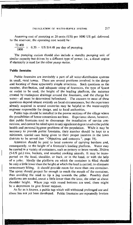
Assuming cost of pumping at 20 cents (US) per 1000 US gal. delivered to the reservoir, the operating cost would be :
72 400 1000
x 0.20 = US $14.48 per day of pumping.
The pumping station should also include a standby pumping unit of similar capacity but driven by a different type of power, i.e., a diesel engine if electricity is used for the other pump motor.
Public fountains
Public fountains are inevitably a part of all water-distribution systems in small, rural towns. There are several problems involved in the design and locating of these apparently simple structures. Such questions as the number, distribution, and adequate siting of fountains, the type of faucet or outlet to be used, the height of the loading platform, the nuisance created by inadequate drainage around the fountains, and the charge for water-all must be determined beforehand. The answers to most of these questions depend almost entirely on local circumstances, but the experience already acquired in several countries may be helpful to the water-supply engineer responsible for design, and to local authorities.
Public taps should be installed in the poorer sections of the village where the possibilities of house connexions are least. Experience shows, however, that public fountains tend to discourage the installation of service con- nexions, and cannot be relied upon to any significant degree to solve the public health and personal hygiene problems of the population. While it may be necessary to provide public fountains, their number should be kept to a minimum, special care being given to their proper location in the town districts to be served (see " Objectives and concepts ", page 18).
Attention should be paid to local customs of carrying burdens and, consequently, to the height of a fountain's loading platform. Water may be carried in a variety of containers, such as pottery or brass vessels, 20-litre (5-US gal.) tins, buckets, and assorted cooking utensils. It may be trans- ported on the head, shoulder, or back, or in the hand, or with the help of a yoke. Ideally the platform on which the container is filled should be only a little lower than the height at which the load is carried, to eliminate unnecessary lifting. It should provide room for more than one container. The spout should project far enough to reach the mouth of the container, thus avoiding the need to tip a jug towards the pillar. Possibly dual platforms are needed, oneat a little lower than the knee, the other at about shoulder height. Where jugs with round bottoms are used, there might be a depression to give firmer support.
As far as is known, a public tap which will withstand prolonged use and abuse has not yet been developed. Public fountains are repeatedly broken
WATER SUPPLY FOR RURAL AREAS
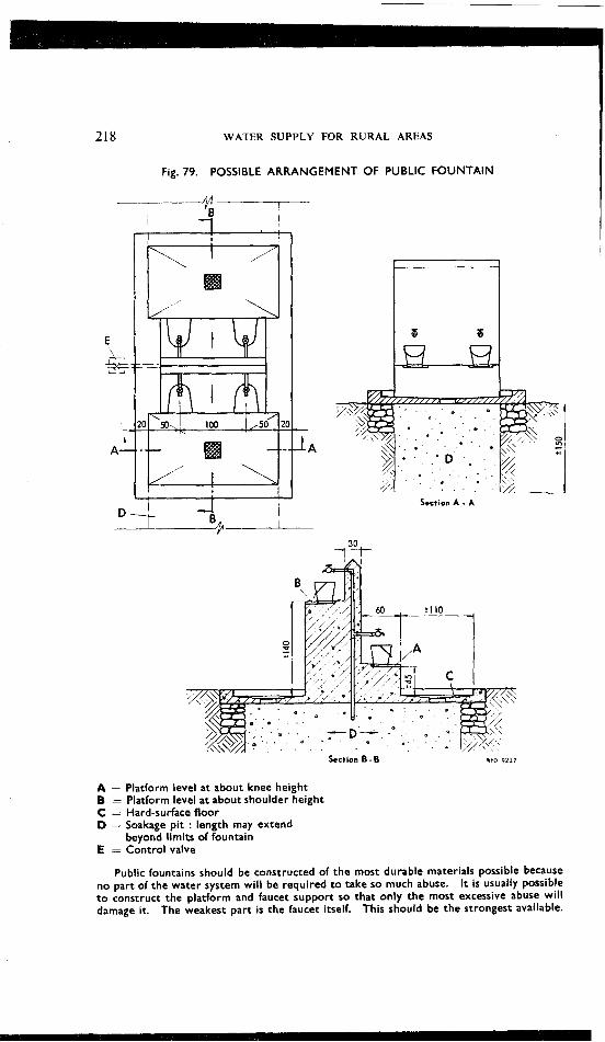
Fig. 79. POSSIBLE ARRANGEMENT OF PUBLIC FOUNTAIN
Section A - A
Section B - B WHO 9211
A = Platform level at about knee height B = Platform level at about shoulder height C = Hard-surface floor D - Soakage p i t : length may extend
beyond limits of fountain E - Control valve
Public fountains should be constructed of the most durable materials possible because no part of the water system wil l be required t o take so much abuse. It is usually possible t o construct the platform and faucet support so that only the most excessive abuse wi l l damage it. The weakest part is the faucet itself. This should be the strongest available.

INSTALLATION OF WATER-SUPPLY SYSTEMS 219
through rough usage and are frequently responsible for considerable water losses, when pressure is high and the discharge orifice is large. Pressure- reducing valves and a reduction of tap sizes will help to limit losses. Public fountains require constant supervision and frequent repairs. One good solution for the operation of fountains is the adoption of a system by which a small charge is made for each can or bucket of water delivered at the foun- tain, this money being used to pay the wages of a public-water-tap operator. Various methods of management of public taps are discussed elsewhere (see page 241). It is necessary to remember that either poor location of fountains or a high water charge, or both, can defeat the public health objectives of the water-supply system by discouraging its use by the popu- lation in favour of a return to the old, unsafe water sources.
Every public fountain should be built with some kind of waste-water- disposal system. Water standing around public fountains can create a serious nuisance and discourage their use. Fig. 79 shows a typical fountain and drainage scheme.
Water losses
There are leaks in every distribution system, no matter how well it is built. But there must be a limit to the amount of water which may be lost in this way; and, in small water-distribution systems especially, there is a need for control of leakage and waste.
The control of water losses usually involves some kind of an inspection system, either personal or mechanical. The mechanical system of inspection implies the use of water meters and gauges which in turn require maintenance and attention and, therefore, are beyond the resources and possibilities of many small towns. Since the major losses in most small towns are to be found in the houses and public fountains, it is here that most effort must be concentrated. A system of private house inspection should be developed which will lead to the discovery and repair of leaky faucets and valves and to the elimination of waste in general. The amount of water lost through carelessness of customers sometimes reaches staggering proportions; it is not uncommon to find towns wasting as much as 75 % of the water supplied.
Laundries and Baths
Public laundries and baths are often included as a part of small town water-supply systems. These are especially needed in areas where bil- harziasis (schistosomiasis) is prevalent. In such areas the transmission of the disease takes place mostly through contact of the skin with river, pool, or canal water which is infected with the parasite of the disease. The danger is particularly great for children who, in the warm climates of bil- harziasis-infested countries, spend much of their play-time wading in rivers,
220 WATER SUPPLY FOR RURAL AREAS
water pools, or irrigation canals which are easily infected by the faecal and urinary discharges of apparently healthy disease-carriers. The provision of public laundries, public baths, and swimming-pools constitutes one of the steps towards preventing the transmission of this debilitating disease.
Public laundries and baths are generally well received by the public and used as long as they are properly maintained. If, however, reasonable cleanliness and maintenance cannot be assured, it is better to spend the construction funds on something else.
In the design of a public laundry, the following points should be carefully observed :
( I ) The planning of an installation which is practical and conforms reasonably well to local customs. For this purpose, the designer should make a close preliminary study of local laundering processes.
(2) The provision of ample drying space. Overhead lines or concrete slabs can be constructed, depending on local customs. In some areas, women refuse to hang clothes on lines and insist on laying them flat on the ground.
(3) The provision of a sufficient supply of water. Although this sounds an obvious requirement, it is not uncommon to find public laundries in which the pipes are too small to supply enough water for laundering processes. The construction of a small storage-tank at the side will help during hours of heavy use of the fountain.
(4) The chemical examination of the water supply for its possible con- tents of iron and manganese compounds. These substances are capable of staining clothes a reddish-brown or black colour.
(5) The drainage of waste water in the vicinity of the public laundry installation.
Similarly, in the case of public baths, the designer should pay particular attention to the physical quality of the water furnished (turbidity, colour, odour), to the drainage of waste water, to the separation of sexes, etc. In the case of swimming-pools in bilharziasis-infected areas, it may even be necessary (depending upon the source of water supply) to enforce chlori- nation of the water to destroy bilharziasis worms (cercariae) in the water. In filtered water cercariae will be killed in 10 minutes by application of chloramine with a 1 p.p.m. chlorine residual at 1 minute. In unfiltered water, they will be killed within 10 minutes by chloramine with 1 p.p.m. chlorine residual at 30 minutes. With calcium hypochlorite solution, cer- cariae will be destroyed within 20 minutes with a chlorine residual at 30 minutes of 0.75 p.p.m.
Protective Measures
The protective measures needed for water-distribution systems aim at conserving the quality of the water obtained at the source all the way to consumers' taps. At many points in a system the quality of the water

INSTALLATION OF WATER-SUPPLY SYSTEMS 22 1
may be altered by any of several factors, among which the following may be cited : the ingress of exterior polluted water through faulty joints or leaks; the growth of bacteria and micro-organisms in the distribution system itself; the solution of chemical substances from the metal system itself; the solution of chemical substances from the metal pipes or from the cement mixtures or other building materials employed for the construction of reservoirs or cisterns; and, finally, the gross pollution obtained from accidental cross-connexions with polluted water pipes. It should be noted that protective measures need to be considered right from the inception of a water-supply and distribution project and should be designed as part of the system. They should also be given attention during construction and pipe-laying operations. It is a fallacy to believe that the disinfection carried out after construction and before operation of the system will be sufficient to sterilize completely the surfaces with which the distributed water will come into contact.
The principal sanitarx measures involve the following : (1) The proper location of reservoirs and distribution pipes. These
should be kept away from direct contact with, or proximity to, all sources of pollution such as sewage or storm-water ditches, latrines, etc. Distri- bution pipes should not be submerged in surface water pools and, wherever possible, should be placed above sewers or drain pipes.
(2) Watertightness of reservoirs and pipes and the elimination of leaks. (3) The maintenance during 24 hours a day of ample pressure in the
system. (4) The planning of the distribution system in such a way as to permit
effective circulation of water and a reduction in the number of dead ends, which favour the growth of bacteria and micro-organisms and the deposition of sediment.
(5) The elimination of cross-connexions. (6) The prevention of back-flow and of entrance of outside water or
materials through such openings as the overflow pipes and manholes of reservoirs, etc.
(7) The use of pipe and construction materials which will not lend themselves to corrosion and solution into the water, thereby creating toxic hazards to the consumers.
These sanitary measures are usually specified in great detail by govern- ments' sanitary codes or regulations, which should always be consulted by the designing engineer.
Hydropneumatic or Pressure System for Individual Homes
When water is unobtainable by gravity and is needed under pressure for use in individual homes, barns and farm installations, and small-scale irrigation, the hydropneumatic-also called " pressure "--system may be

222 WATER SUPPLY FOR RURAL AREAS
installed with advantage. Usually such a system is employed where electric power is available for its operation.
As shown in Fig. 80, this system consists essentially of an electrically driven pump and a pressure tank partly filled with air. Water is pumped into the lower part of the tank, compressing the air above it. When the pressure reaches a predetermined maximum figure (usually 2.72 atm., or 40 p.s.i.), the automatic switch opens and shuts off the motor and pump. As water is drawn out of the tank, the pressure drops; and, when it reaches a pre-set minimum (usually 1.36 atm., or 20 p.s.i.), the automatic switch closes and starts both motor and pump again.
Fig. 80. PRESSURE TANK SYSTEM
A = Pump and motor B = Automatic switch C = Pressure tank D = Water level corresponding to minimum pressure (usually 1.36 atrn., or 20 p.s.i.) E = Water level corresponding to maximum pressure (usually 2.72 atrn.. or 40 p.s.i.) F - Air in tank
Various types and designs are available on the market and are usually sold together with instructions for their installation, operation, and mainten- ance. The pump used may be of either the displacement or the velocity

INSTALLATION OF WATER-SUPPLY SYSTEMS 223
type. When a reciprocating pump is used, the system should always be provided with a pressure-relief valve, since dangerous pressures may be built up in the tank if, for unexpected reasons, the automatic switch should fail to operate. For ordinary household needs, a pressure tank of about 160-litre (42-US gal.) capacity will suffice. If peak demands should be created by such circumstances as lawn-sprinkling or irrigation, a larger installation will be recommended by manufacturers or their commercial representatives. Electrically driven pressure systems are compact; and, being completely automatic, they require a minimum of attention and main- tenance. An ordinary household unit equipped with a 160-litre (42-US gal.) tank and capable of a maximum pressure of 4-4.8 atm. (60-70 p.s.i.) may be obtained on the market at an average cost of US $160.00 (1958).


