Embed Size (px)
Citation preview

8/12/2019 Monocular Diplopia Due to Spherocylindrical Refractive Errors
http://slidepdf.com/reader/full/monocular-diplopia-due-to-spherocylindrical-refractive-errors 1/20
Trans Am Ophthalmol Soc / Vol 105/ 2007 252
MONOCULAR DIPLOPIA DUE TO SPHEROCYLINDRICAL REFRACTIVE ERRORS (AN AMERICAN
OPHTHALMOLOGICAL SOCIETY THESIS)
BY Steven M. Archer MD
ABSTRACT
Purpose: Ordinary spherocylindrical refractive errors have been recognized as a cause of monocular diplopia for over a century, yet
explanation of this phenomenon using geometrical optics has remained problematic. This study tests the hypothesis that the diffractiontheory treatment of refractive errors will provide a more satisfactory explanation of monocular diplopia.
Methods: Diffraction theory calculations were carried out for modulation transfer functions, point spread functions, and line spread
functions under conditions of defocus, astigmatism, and mixed spherocylindrical refractive errors. Defocused photographs of inkedand projected black lines were made to demonstrate the predicted consequences of the theoretical calculations.
Results: For certain amounts of defocus, line spread functions resulting from spherical defocus are predicted to have a bimodalintensity distribution that could provide the basis for diplopia with line targets. Multimodal intensity distributions are predicted in
point spread functions and provide a basis for diplopia or polyopia of point targets under conditions of astigmatism. The predicted
doubling effect is evident in defocused photographs of black lines, but the effect is not as robust as the subjective experience of
monocular diplopia.
Conclusions: Monocular diplopia due to ordinary refractive errors can be predicted from diffraction theory. Higher-order
aberrations—such as spherical aberration—are not necessary but may, under some circumstances, enhance the features of monocular
diplopia. The physical basis for monocular diplopia is relatively subtle, and enhancement by neural processing is probably needed to
account for the robustness of the percept.
Trans Am Ophthalmol Soc 2007;105:252-271
INTRODUCTION
Monocular diplopia or polyopia can be experienced by almost everyone under certain circumstances. Phenomena such as the doubling
of the horns of a crescent moon, splitting of a fine white line on a black or a black line on a white background—all made more
pronounced by defects of focus—have been repeatedly mentioned in the literature over many years.1,2 Monocular diplopia accountedfor 25% of diplopia cases presenting to an ophthalmic casualty department. 3 Yet when presented with a complaint of diplopia
clinicians often overlook monocular causes, presuming the problem to be of binocular origin.
Monocular diplopia due to nonoptical causes is extraordinarily rare. Psychiatric disease or malingering is often suspected 4,5
however, Morris3 found that most cases have an organic explanation. Monocular diplopia associated with neurologic lesions has been
described.6 Sensory adaptations to strabismus7-10 and treatment of amblyopia11 can produce monocular diplopia. A few cases o
monocular diplopia with retinal pathology have been reported.3,4
The vast majority of monocular diplopia, however, is optical in origin.12 Some optical etiologies are relatively easy to understandExtrapupillary apertures such as with iridodialysis or iridectomy can function as a Scheiner’s disc.13,14 Lens abnormalities such as
cataract, subluxation, or other lenticular abnormality12,14,15 and corneal abnormalities such as keratoconus or other corneal
pathology5,16,17
can result in monocular diplopia. Monocular diplopia can result from pressure on the cornea by a chalazion14,18
or bythe eyelids during prolonged reading, near work, or television viewing.19-24 Corneal aberrations after refractive corneal surgery are an
increasingly important cause of monocular diplopia.25-29 Reflections from spectacle lens surfaces30,31 have been implicated in
monocular diplopia. Although it is usually subclinical, being either unnoticed or regarded as a normal state of affairs by those whoobserve it, the most common monocular diplopia is that occurring in otherwise normal eyes, with or without refractive errors.
PHYSIOLOGICAL MONOCULAR DIPLOPIA
Fincham32 stated that physiological monocular diplopia occurs in 40% to 50% of otherwise normal eyes. It can be cause for clinical
complaint33 but is usually so minor that only the occasional highly perceptive patient with otherwise good vision will remark about it
spontaneously. Most individuals are unaware of it until it is demonstrated to them under special testing conditions. A bright line on a
dark background is a particularly effective stimulus for eliciting physiological monocular diplopia,8,32 which is characterized by a fainsecondary image that is displaced 3 to 6 minutes of arc upward from the primary image. Moving a pinhole in front of the eye will
cause a jump from one image to the other, and blocking the upper or lower portion of the pupil with a card will usually eliminate the
second image.8,32,33 Taken together, these findings suggest that variation of the refractive power from one area of the pupillary apertureto another is the cause of the diplopia.
Guyton8 states that the cornea is responsible for 40% of the optical aberrations resulting in monocular diplopia, with the crystalline
lens being responsible in roughly 60% of cases. Rubin12 suggests that minor imperfections in the optical system of the eye, such as the
optical axes of the cornea and lens not being coincident, are the cause. In a study of 70 individuals with normal visual acuityFincham32 found that differences of 0.5 diopter or more in refractive power between the upper and lower portions of the pupil
correlated with the observation of this form of physiological monocular diplopia. Uncorrected spherocylindrical refractive error is no
From the Department of Ophthalmology and Visual Sciences, University of Michigan, Ann Arbor.

8/12/2019 Monocular Diplopia Due to Spherocylindrical Refractive Errors
http://slidepdf.com/reader/full/monocular-diplopia-due-to-spherocylindrical-refractive-errors 2/20
Archer
Trans Am Ophthalmol Soc / Vol 105/ 2007 253
necessary for physiological monocular diplopia, which occurs in spite of full optical correction; yet Fincham found that in some casesthe diplopia was enhanced by simulation of myopia with the introduction of a weak positive lens. He also noted that astigmatism could
produce a more distinct doubling of a bright line in some axes with a dark space appearing between the two images, which is differen
from the description of typical physiological monocular diplopia and may represent a different phenomenon altogether.
ORDINARY SPHEROCYLINDRICAL REFRACTIVE ERRORS
Monocular diplopia occurring with ordinary refractive errors has been recognized by clinicians since at least the 19th century, when
Bull34 concluded that “all eyes and in every case of refractive error, including the common cases of myopia and hypermetropia, the
many varieties of astigmic vision, and the case of objects slightly outside the p.r . or the p.p., there is to be found the phenomenonusually denoted by the term monocular diplopia….” Scott35 states that monocular diplopia due to myopia or myopic astigmatism is the
most common form of nonstrabismic diplopia that he sees. Uncorrected simple astigmatism was implicated as the cause in two cases
from Stampfer and Tredici’s series of flying personnel with monocular diplopia, 14 and simulated astigmatism reproducibly results indiplopia experimentally.36
Case Reports
The following cases have been selected to illustrate how, even when the referring ophthalmologist is aware of the potential for
ordinary refractive errors to cause diplopia, the correct diagnosis can be missed, especially when there is a coexisting condition to
which the diplopia could be attributed.Case 1. A 7-year-old boy is referred for a complaint of diplopia. The uncorrected visual acuity is 20/20 in the right eye and 20/40
in the left eye. On further testing, the diplopia is monocular, worse in the left eye than the right, and relieved with a pinhole.
Cycloplegic retinoscopy shows a refraction of –0.75 + 0.75 × 90 in the right eye and –1.00 + 0.50 × 90 in the left eye.
It is unusual for children to have perception so acute that they would complain about the diplopia with refractive errors. This case
illustrates that sometimes relatively small refractive errors are particularly efficient at eliciting this complaint.Case 2. A 63-year-old man is referred by his cornea surgeon for a complaint of diplopia in his pseudophakic eye 1 week after
cataract surgery. His manifest refraction in the cornea surgeon’s office was –1.50 + 2.50 × 110 that results in an acuity of 20/60
Retinoscopy shows a refraction of –3.50 + 6.00 × 110 that results in an acuity of 20/25. This refraction eliminates his diplopia, and heis referred back to his cornea surgeon for cutting of a suture.
The monocular diplopia in this case was due to a large amount of astigmatism. The astigmatism was not fully appreciated on
manifest refraction because it was so far outside of the expected range.
Case 3. A 55-year-old dentist is referred for complaint of monocular diplopia, worse in the right eye than the left for 5 months. He
has a history of amblyopia in the right eye and esotropia but has had no strabismus surgery. His visual acuity is 20/160 in his right eye
and 20/20 in his left eye with his current spectacles, which measure –2.00 + 2.00 × 100 in the right eye and –1.50 + 0.25 × 70 in theleft eye. His motility examination shows a 5∆ esotropia at near and a 6∆ esotropia and 2∆ right hypertropia at near.
A 5∆ base-out prism provides minimal improvement. A pinhole eliminates the diplopia in either eye. Retinoscopy shows a
refraction of –4.75 + 1.00 × 75 in the right eye that improves the acuity to 20/60 and eliminates the diplopia. Manifest refraction of the
left eye is –1.75 +0.50 × 70 and eliminates the “shadowing” in that eye.The diplopia in this case is due to undercorrection of myopia in the amblyopic right eye. In spite of the temptation to attribute his
problems to the strabismus and amblyopia history, this patient comes with a description of diplopia that is clearly monocular. Thereason that this case was not diagnosed by the referring ophthalmologist stems from the difficulty in obtaining an accurate subjective
refraction in an amblyopic eye, along with the failure to recognize that, as is the case with strabismic diplopia, an eye with reducedvision is still sometimes capable of producing a complaint of diplopia.
Case 4. A 90-year-old bilaterally pseudophakic woman with a 6-year history of diplopia, satisfactorily corrected with prism in her
spectacles until 6 months previously, is referred because her ophthalmologist was now unable to find any prism that eliminates her
diplopia. Her vision is 20/30- in each eye with her current spectacles, which measure –0.25 + 1.00 × 38 in the right eye and –1.25 +
3.25 × 175 in the left eye with 1.5∆ base-out in each eye. Her motility examination shows 6∆ of esotropia in primary position atdistance that increases to 14∆ in right gaze. At near she is orthophoric.
Her esotropia in primary position is neutralized by a total of 6∆ base-out prism, but she continues to complain of seeing multiplestrokes on each letter on the eye chart. On further investigation, it is found that this is not eliminated by covering either eye and is
eliminated with a pinhole. Retinoscopy shows a refraction of –2.75 + 2.25 × 25 in her right eye and –2.75 + 1.25 × 10 in her left eyeThis does not improve her acuity but eliminates the multiple strokes on the letters and, along with 6∆ base-out prism, eliminates all ofher diplopia.
This patient has strabismus due to a slowly progressive sixth nerve palsy (and was subsequently referred to a neuroophthalmologist for evaluation). When prismatic correction of the esotropia did not eliminate her diplopia, the remaining diplopia
needed to be re-investigated to discover that she also has bilateral monocular diplopia due to inadequate correction of her refractive
error.
Case 5. A 60-year-old woman is referred for diplopia that she has had ever since 2 pars plana vitrectomies and membrane peelingin her right eye 2 years ago. She reports that the diplopia is worst when reading, there is a size difference in the images of the 2 eyes
and that the image in the right eye is distorted. She has a history of “lazy eye” as a child and is pseudophakic in her right eye. Her
visual acuity is 20/30 in the right eye and 20/20 in the left eye with her current spectacles, which are plano + 1.00 × 135 in the righ

8/12/2019 Monocular Diplopia Due to Spherocylindrical Refractive Errors
http://slidepdf.com/reader/full/monocular-diplopia-due-to-spherocylindrical-refractive-errors 3/20
Monocular Diplopia Due to Spherocylindrical Refractive Errors
Trans Am Ophthalmol Soc / Vol 105/ 2007 254
eye and +0.75 + 0.50 × 90 in the left eye. Her motility examination shows a 12∆ intermittent exotropia at near and a 5∆ intermittenexotropia at distance.
A pinhole over the right eye eliminates the diplopia. Retinoscopy shows a refraction of +0.25 + 0.50 × 10. This refraction, alongwith 1∆ base-up in the right eye (along with the same +2.50 addition for reading that she had in her present spectacles) produced a
dramatic subjective improvement in her reading vision and eliminated her diplopia.This patient’s diplopia could have been attributed to her convergence insufficiency pattern intermittent exotropia, or
metamorphopsia of retinal origin. Further investigation revealed that most of her symptoms were due to the small amount of
astigmatic correction in her right spectacle lens that was 55º from the correct axis.
Demonstration
Most people can experience the diplopia that accompanies optical defocus for themselves. Scott35 offers a demonstration of diplopia
with myopic defocus. He instructs the reader to hold a black thread in front of a bright background at a distance of 2 feet and to focus
monocularly on a finger held between the eye and the thread. As the finger is brought closer to the eye (that is, the image of the thread
falls further in front of the retina), the thread will blur and then become distinctly double, with the images of the thread becomingincreasingly separated as the finger is brought closer to the eye. In this demonstration, Scott does not note diplopia when focusing on a
finger held further from the eye than the thread. However, a fine black line on white paper, viewed monocularly, can be used to
demonstrate diplopia with hyperopic defocus in most individuals.14 As the paper is moved closer to the eye than the near point of
accommodation (the image of the line falls behind the retina), doubling, trebling, or even quadrupling of the line can be observed. This phenomenon can be utilized as the end point in testing for the near point of accommodation with the “accommodation test” on the
back of a widely distributed version of the Lebensohn near card. As the card is brought closer to the eye, the 2 fine parallel black line
appear to be 3 lines when the innermost of the second images of each line overlap, indicating that a degree of hyperopic defocus hasoccurred.
Coffeen and Guyton37 showed experimentally that most people are able to appreciate monocular diplopia with both hyperopic andmyopic defocus. By inducing myopic refractive errors in otherwise normal test subjects, they found that 9 of 11 eyes experienced
doubling of black lines on a white background, either projected on a screen or inked on white paper. With induced hyperopia, 7 of 11eyes experienced diplopia with projected lines and 9 of 11 with inked lines. On average, diplopia developed with –1.57 D of myopic
defocus when projected lines were used and –2.19 D with inked lines. The average amount of hyperopic defocus needed to producediplopia was +1.14 D and +1.69 D for projected and inked lines, respectively.
On the other hand, Guyton8 at one time stated that simple refractive errors such as myopia, hyperopia, and astigmatism do not
cause diplopia. This statement—despite reports to the contrary and the daily personal experience of those of us with uncorrected mild
myopia—is perhaps a reflection of the difficulty in imagining a plausible mechanism by which ordinary spherocylindrical refractiveerrors could cause diplopia.
Geometrical Optics
Attempts to explain the doubling of an image in a defocused human eye have relied almost exclusively on geometrical optics analysis
In geometrical optics, the defocused image of a point (point spread function) is a blur circle of uniform intensity. The diameter of the blur circle increases as the image falls further in front of or behind the retina, but the form of the point spread function is always a
circle. The image of a line (line spread function) under conditions of defocus can be obtained by imagining a series of defocused
points falling along the line. Integrating along vertical chords through the blur circle of the point spread function (Figure 1) gives the
intensity of the line spread function at a given eccentricity from the center of the line (Figure 2).38,39 Like the point spread function, thescale of this line spread function changes with increasing defocus, but its form does not. It is clear that doubling of a fine white line on
a dark background cannot be explained by the geometrical optics of simple defocus alone.
FIGURE 1
The line spread function is calculated by integration along
chords through the point spread function.
FIGURE 2
The intensity profile of a defocused line (line
spread function) according to the principles ofgeometrical optics.

8/12/2019 Monocular Diplopia Due to Spherocylindrical Refractive Errors
http://slidepdf.com/reader/full/monocular-diplopia-due-to-spherocylindrical-refractive-errors 4/20
Archer
Trans Am Ophthalmol Soc / Vol 105/ 2007 255
Analysis of the blurred image of a black line on a white background is more involved. A black line can be regarded as a gap between 2 bright edges. An edge can be constructed as the summation of a series of parallel lines, the intensity at positions near the
edge being the sum of the contributions from all of the lines on the bright side of the edge close enough that their line spread function
overlap that position. The edge spread function can therefore be computed as the running integral of the line spread function (Figure3).38,39 Two of these edges can then be superimposed with various amounts of separation to model black lines of various widths
(Figure 4). With the defocused edge spread function predicted from geometrical optics, there is no separation of the edges tha
produces a band of increased intensity in the dark gap between the 2 edges that could give rise to monocular diplopia (Figure 5).
FIGURE 3
The intensity profile of a defocused edge between white
and black areas (edge spread function) according to the
principles of geometrical optics.
FIGURE 4
A defocused black line is constructed from 2 defocused edges (dashed lines). The summation of the 2 edges (solid
line) has been shifted upward for clearer visualization. A,Top left, When the edges abut, the result is a field of
uniform intensity. Top right and Bottom, As the edges are separated, a deepening depression in the intensity profile develops between them.

8/12/2019 Monocular Diplopia Due to Spherocylindrical Refractive Errors
http://slidepdf.com/reader/full/monocular-diplopia-due-to-spherocylindrical-refractive-errors 5/20
Monocular Diplopia Due to Spherocylindrical Refractive Errors
Trans Am Ophthalmol Soc / Vol 105/ 2007 256
Coffeen and Guyton37 conclude that an inflection in the defocused edge spread function, an exaggerated but unrealizable exampleof which is shown in Figure 6, is needed in order to produce doubling of a black line on a white background (Figure 7). Figure 8
shows that, with the hypothetical defocused edge spread function shown in Figure 6, a bright band develops in the gap when the
separation is less than approximately 50% of the width of the line spread function. Differentiation of the edge spread function returnsthe form of the line spread function from which it was formed (Figure 9). It is obvious that with this line spread function, monocular
diplopia of a fine white line on a dark background can be accounted for as well.
FIGURE 5
The intensity profile of a defocused black line as a
function of the gap between the 2 edges of which it is
composed. The gap distance is plotted as a fraction of the
edge spread width. With the defocused edge spreadfunction derived from geometrical optics, there is no gap
distance at which there is an intensity ridge in the gap
between the 2 edges that could give rise to the perception
of doubling of the black line.
FIGURE 6
A hypothetical defocused edge spread function with the
inflection that is necessary to produce monocular
diplopia.
FIGURE 7The defocused black line constructed from hypotheticaledge spread functions with an inflection (dashed lines).
The summation of the 2 edges (solid line) has been shifted
upward for clearer visualization. Top left, When the edgesabut, the result is a field of uniform intensity. Top right,
With small separations of the edges, a ridge of increased
intensity develops in the gap that would give the
appearance of splitting of the black line. Bottom, When theseparation is too large for the inflections in the edge spread
functions to overlap, the ridge disappears.

8/12/2019 Monocular Diplopia Due to Spherocylindrical Refractive Errors
http://slidepdf.com/reader/full/monocular-diplopia-due-to-spherocylindrical-refractive-errors 6/20
Archer
Trans Am Ophthalmol Soc / Vol 105/ 2007 257
Thus, a bimodal line spread function implied by the doubling of a fine white line on a black background also appears to be a
sufficient condition for doubling of a fine black line on a white background. But how could a bimodal line spread function be
produced by simple defocus? Because geometrical optics offers no possible mechanism by which this might occur, many investigatorhave postulated that additional aberrations—usually spherical aberration—must be present to account for the observed
phenomena.30,35,37,40,41 Ray-tracing analysis suggests that negative spherical aberration in myopic eyes30,35 and positive spherica
aberration in hyperopic eyes30,41 could produce the bimodal line spread needed to explain monocular diplopia. However, explanationof monocular diplopia with both positive and negative defocus in the same eye, as found by Coffeen and Guyton, requires a
complicated pattern of aberration37,40
that seems unlikely to occur as consistently as the phenomenon of monocular diplopia.
FIGURE 8The intensity profile of a defocused black line as a
function of the gap between two hypothetical edgespread functions with an inflection. An intensity
ridge giving the perception of splitting of the
black line develops in the gap when the separation
between the edges is less than half the width ofthe edge spread function.
FIGURE 9The bimodal intensity profile of the line spread
function that gives rise to the theoretical edgespread function shown in Figure 6, which is
capable of producing monocular diplopia with a
black line target.
Diffraction Theory
Geometrical optics is a special case of diffraction theory in which the limit of the wavelength of light approaches zero. 42 This
simplification yields a useful approximation of the properties of an optical system—such as the human eye—in many respects38,43-45
however, the results can differ from diffraction theory in the fine structure of image formation, especially for small amounts of
defocus. In undertaking analysis by diffraction theory, it is often convenient to evaluate the performance an optical system in terms ofits spatial frequency response (modulation transfer function). The modulation transfer function of a defocused eye can be calculated
theoretically.38,46 Point spread and line spread functions can be computed from the modulation transfer function by inverse Fourier
transformation39,47; however, this methodology has not, to my knowledge, been applied to theoretical modulation transfer functions o
a defocused eye in the context of accounting for the monocular diplopia that arises from ordinary refractive errors.
Hypothesis
When image formation in an eye is modeled using diffraction theory, point spread and line spread functions under conditions of
defocus and astigmatism—without invoking higher-order aberrations—will be found to have inherent characteristics that provide a
basis for monocular diplopia.

8/12/2019 Monocular Diplopia Due to Spherocylindrical Refractive Errors
http://slidepdf.com/reader/full/monocular-diplopia-due-to-spherocylindrical-refractive-errors 7/20
Monocular Diplopia Due to Spherocylindrical Refractive Errors
Trans Am Ophthalmol Soc / Vol 105/ 2007 258
METHODS
THEORETICAL CALCULATIONS
Computations assumed a 3-mm-diameter entrance pupil and light with a wavelength of 555 nm, although results can be scaled for
other wavelengths or pupil diameters. After Hopkins,43 the amount of defocus is characterized by w20=nλ/π, where w20 is the distance
between the defocused and aberration-free wavefront at the edge of the pupil and λ is the wavelength. An n of 20 is equivalent to
approximately 3 D of defocus in an eye with a 3-mm entrance pupil and a reduced focal length of 16.78 mm. Calculations were made
for increasing amounts of defocus, n, in increments of 1.Diffraction in an optical system with a finite pupil acts as a low-pass spatial frequency filter with an absolute spatial frequency
cutoff,46,48,49 making it possible to satisfy the conditions of the sampling theorem50,51; thus, image formation in the eye is suitable for
analysis using discrete Fourier transform techniques. Algorithms for the computation of Bessel functions51
and discrete inverse fasFourier transforms50,51 were custom-programmed in JSL, executed and results plotted using JMP versions 5.1.1 through 6.03 (SAS
Institute Incorporated, Cary, North Carolina).
Modulation Transfer Function
Several approaches to the computation of modulation transfer functions for defocused Fraunhofer diffraction images have beendescribed.43,52 In this study, the method described by Hopkins43 —which expresses the modulation transfer function as a
computationally efficient convergent series of Bessel functions—was used. The frequency response was calculated at 0.46
cycle/degree intervals. Two-dimensional modulation transfer functions for astigmatic errors were calculated according to the
computationally similar method described by De53 at 0.88 cycle/degree intervals.
Line Spread Function
The line spread function and the modulation transfer function are related to each other by the Fourier transform. 48,54 In this study, theline spread functions for defocus were calculated by inverse discrete fast Fourier transform of the modulation transfer functions
Intensities were calculated at intervals of 4 seconds of arc.
Point Spread Function
In the radially symmetric case of simple defocus, the inverse Fourier transforms of the modulation transfer functions were computed
by numerical integration of the inverse Hankel transform to obtain the point spread functions.47,49 Intensities were calculated a
intervals of 1 second of arc. Inverse 2-dimensional discrete fast Fourier transforms of the astigmatic modulation transfer functions
were used to obtain point spread functions for astigmatic errors. Intensities were calculated at intervals of 4 seconds of arc.
PHOTOGRAPHIC DEMONSTRATIONS
The theoretical point spread and line spread functions should be directly applicable to the question of monocular diplopia occurring
with defocused targets consisting of thin bright lines or bright points. However, the relationship of these results to monocular diplopiawith commonly encountered real-world targets is more complex. To demonstrate the effects of defocus with black lines of finite
width, inked lines on white paper created by a laser printer were photographed with a Nikon D100 camera with a Nikkor 24-85 mmlens used at an 85-mm focal length, ƒ/8 (Nikon, Tokyo, Japan). The lines subtended approximately 0.45, 0.9, and 1.8 minutes of arc athe camera, respectively. The camera lens was adjusted for optimal focus, and a series of photos were then taken with the lens
progressively defocused.
To obtain higher contrast, projected lines were used in the second photographic demonstration. A slide with black lines on a clear
background was projected with an Ektographic III AM projector (Kodak, Rochester, New York) using a Vario-Prolux MC 70-120 mm
ƒ/2.8 lens (Schneider Optics, Hauppauge, New York) at a 120-mm focal length. The images were projected on screen (Da-LiteWarsaw, Indiana) 3.2 m from the projector and photographed with the same Nikon camera from a distance of 3.6 m. The projector
lens was focused optimally, and photographs of the screen were taken as the projector lens was progressively defocused.
RESULTS
THEORETICAL CALCULATIONS
Modulation Transfer Function With DefocusThe modulation transfer functions for selected amounts of defocus are shown in Figure 10. As expected, higher spatial frequencies
initially suffer more reduction of contrast with defocus than lower spatial frequencies. However, at a certain level of defocus (Figure
10, top middle), the modulation transfer function begins to develop zero crossings with intervening bands of spatial frequencies that
have negative contrast (Figure 10, top right, and bottom left, middle, and right). Negative contrast represents phase reversal and leadsto the phenomenon of spurious resolution.45,55 With increasing defocus, these zero crossings become more numerous and the bands of
negative contrast migrate toward the lower spatial frequencies.
Point Spread Function With Defocus
Point spread functions for selected amounts of defocus, shown in Figure 11, show a shift of energy from the central peak out into thesurrounding ring structure with defocus. As defocus increases, the point spread function cycles between maxima and minima at the

8/12/2019 Monocular Diplopia Due to Spherocylindrical Refractive Errors
http://slidepdf.com/reader/full/monocular-diplopia-due-to-spherocylindrical-refractive-errors 8/20
Archer
Trans Am Ophthalmol Soc / Vol 105/ 2007 259
center. While having a minimum in the center of the point spread function is conducive to the formation of the bimodal line spread
function needed to explain monocular diplopia, the diameter of the outermost ring structure will determine the spatial scale of the bimodal or multimodal line spread function.
FIGURE 10
Modulation transfer functions calculated from diffraction theory for various amounts of spherical defocus, n. The verticalaxis is the fraction of transmission. The horizontal axis is the spatial frequency, scaled according to the cutoff frequency for
the aperture, which is normalized to a value of 2. In addition to reduced transmission that affects higher spatial frequenciesmore severely than lower spatial frequencies, phase reversals (negative regions of the modulation transfer function) develop
with increasing defocus. Top left, n=1. Top middle, n=2. Top right, n=3. Bottom left, n=4.5. Bottom middle, n=6. Bottom
right, n=8.
Line Spread Function With Defocus
Figure 12 shows the line spread functions for selected amounts of defocus. Certain amounts of defocus result in a bimodal intensity
distribution on a spatial scale that should be readily perceived by a human eye and provides an obvious basis for monocular diplopia
(Figure 12, top right). With further defocus, the increasingly complex line spread functions (Figure 12, bottom) recall the classic
descriptions by von Helmholtz,2 Bull,
34 Verhoeff,
40 and Emsley
1 of intricate banding as target lines are blurred beyond the initia
perception of doubling.
Point Spread Function With Astigmatism
Pure astigmatic defocus—such as myopic astigmatism, in which the effects of the astigmatic error cannot be mitigated by
accommodation—results in the point spread functions shown in Figure 13. In Figure 13, top right, it can be appreciated how
astigmatism could produce a bimodal image and consequent monocular diplopia. Further defocus results in a multimodal intensitydistribution and potential diplopia or polyopia (Figure 13, bottom). Note that while spherical defocus can result in diplopia with a line
target, astigmatism can produce diplopia with even a point. From this observation, it might be expected that myopic astigmatism will
be the most clinically important cause of monocular diplopia.
Point Spread Function With Astigmatism—Circle of Least Confusion
Figure 14 shows point spread functions for various amounts of astigmatic defocus in the plane of the circle of least confusion. Thissituation might occur with hyperopic astigmatism, where the patient is able to accommodate to place the circle of least confusion at
the plane of the retina. Here, too, a multimodal point spread function potentially leads to polyopia from a single point, although it
requires more defocus to produce these effects than with the previous forms of aberration.

8/12/2019 Monocular Diplopia Due to Spherocylindrical Refractive Errors
http://slidepdf.com/reader/full/monocular-diplopia-due-to-spherocylindrical-refractive-errors 9/20
Monocular Diplopia Due to Spherocylindrical Refractive Errors
Trans Am Ophthalmol Soc / Vol 105/ 2007 260
FIGURE 11
Point spread functions calculated from diffraction theory for various amounts of spherical defocus, n. The vertical axis, intensity,
is linear but scaled proportionally to the log of the maximal value in each point spread function. With increasing defocus, the
center of the point spread function cycles between maxima and minima. Top left, n=1. Top middle, n=2. Top right, n=3. Bottomleft, n=4.5. Bottom middle, n=6. Bottom right, n=8.
FIGURE 12
Line spread functions calculated from diffraction theory for various amounts of defocus, n. A bimodal line spread function
develops for some amounts of defocus, forming the basis for monocular diplopia with spherical defocus of a bright line. Scaling is
as in Figure 11. Top left, n=1. Top middle, n=2. Top right, n=3. Bottom left, n=4.5. Bottom middle, n=6. Bottom right, n=8.

8/12/2019 Monocular Diplopia Due to Spherocylindrical Refractive Errors
http://slidepdf.com/reader/full/monocular-diplopia-due-to-spherocylindrical-refractive-errors 10/20
Archer
Trans Am Ophthalmol Soc / Vol 105/ 2007 261
FIGURE 13
Point spread functions calculated from diffraction theory for various amounts of astigmatic error, n. A bimodal pointspread function develops for some amounts of astigmatic error, forming the basis for monocular diplopia and polyopia of a
bright point target. Scaling is as in Figure 11. Top left, n=1. Top middle, n=2. Top right, n=3. Bottom left, n=4.5. Bottom
middle, n=6. Bottom right, n=8.
FIGURE 14
Point spread functions calculated from diffraction theory for various amounts of astigmatic error, n, combined with
spherical defocus of –n/2 (in the plane of the circle of least confusion). This produces complex point spread functions that
may give rise to polyopia with a bright point target. Scaling is as in Figure 11. Top left, n=1. Top middle, n=2. Top right,n=3. Bottom left, n=5. Bottom middle, n=6. Bottom right, n=8.
8/12/2019 Monocular Diplopia Due to Spherocylindrical Refractive Errors
http://slidepdf.com/reader/full/monocular-diplopia-due-to-spherocylindrical-refractive-errors 11/20
Monocular Diplopia Due to Spherocylindrical Refractive Errors
Trans Am Ophthalmol Soc / Vol 105/ 2007 262
PHOTOGRAPHIC DEMONSTRATIONS
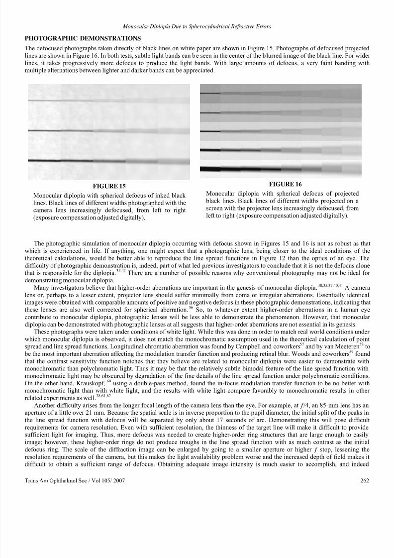
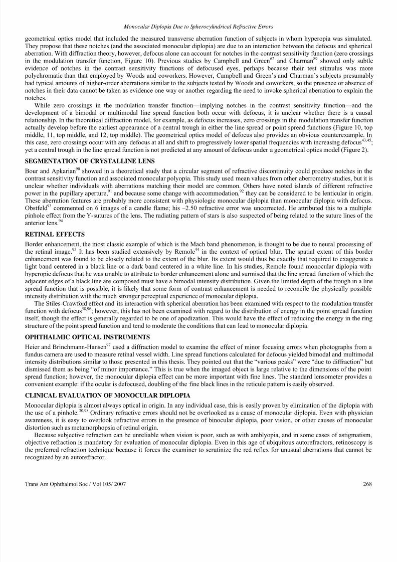
The defocused photographs taken directly of black lines on white paper are shown in Figure 15. Photographs of defocused projected
lines are shown in Figure 16. In both tests, subtle light bands can be seen in the center of the blurred image of the black line. For wide
lines, it takes progressively more defocus to produce the light bands. With large amounts of defocus, a very faint banding withmultiple alternations between lighter and darker bands can be appreciated.
FIGURE 15
Monocular diplopia with spherical defocus of inked blacklines. Black lines of different widths photographed with thecamera lens increasingly defocused, from left to right
(exposure compensation adjusted digitally).
FIGURE 16
Monocular diplopia with spherical defocus of projected black lines. Black lines of different widths projected on ascreen with the projector lens increasingly defocused, from
left to right (exposure compensation adjusted digitally).
The photographic simulation of monocular diplopia occurring with defocus shown in Figures 15 and 16 is not as robust as tha
which is experienced in life. If anything, one might expect that a photographic lens, being closer to the ideal conditions of thetheoretical calculations, would be better able to reproduce the line spread functions in Figure 12 than the optics of an eye. The
difficulty of photographic demonstration is, indeed, part of what led previous investigators to conclude that it is not the defocus alonethat is responsible for the diplopia.34,40 There are a number of possible reasons why conventional photography may not be ideal for
demonstrating monocular diplopia.
Many investigators believe that higher-order aberrations are important in the genesis of monocular diplopia. 30,35,37,40,41 A camera
lens or, perhaps to a lesser extent, projector lens should suffer minimally from coma or irregular aberrations. Essentially identicalimages were obtained with comparable amounts of positive and negative defocus in these photographic demonstrations, indicating tha
these lenses are also well corrected for spherical aberration.56 So, to whatever extent higher-order aberrations in a human eye
contribute to monocular diplopia, photographic lenses will be less able to demonstrate the phenomenon. However, that monoculardiplopia can be demonstrated with photographic lenses at all suggests that higher-order aberrations are not essential in its genesis.
These photographs were taken under conditions of white light. While this was done in order to match real world conditions under
which monocular diplopia is observed, it does not match the monochromatic assumption used in the theoretical calculation of pointspread and line spread functions. Longitudinal chromatic aberration was found by Campbell and coworkers57 and by van Meeteren58 to
be the most important aberration affecting the modulation transfer function and producing retinal blur. Woods and coworkers59 found
that the contrast sensitivity function notches that they believe are related to monocular diplopia were easier to demonstrate withmonochromatic than polychromatic light. Thus it may be that the relatively subtle bimodal feature of the line spread function with
monochromatic light may be obscured by degradation of the fine details of the line spread function under polychromatic conditions
On the other hand, Krauskopf, 60 using a double-pass method, found the in-focus modulation transfer function to be no better with
monochromatic light than with white light, and the results with white light compare favorably to monochromatic results in otherrelated experiments as well.38,61,62
Another difficulty arises from the longer focal length of the camera lens than the eye. For example, at ƒ/4, an 85-mm lens has anaperture of a little over 21 mm. Because the spatial scale is in inverse proportion to the pupil diameter, the initial split of the peaks in
the line spread function with defocus will be separated by only about 17 seconds of arc. Demonstrating this will pose difficult
requirements for camera resolution. Even with sufficient resolution, the thinness of the target line will make it difficult to providesufficient light for imaging. Thus, more defocus was needed to create higher-order ring structures that are large enough to easily
image; however, these higher-order rings do not produce troughs in the line spread function with as much contrast as the initial
defocus ring. The scale of the diffraction image can be enlarged by going to a smaller aperture or higher ƒ stop, lessening the
resolution requirements of the camera, but this makes the light availability problem worse and the increased depth of field makes itdifficult to obtain a sufficient range of defocus. Obtaining adequate image intensity is much easier to accomplish, and indeed

8/12/2019 Monocular Diplopia Due to Spherocylindrical Refractive Errors
http://slidepdf.com/reader/full/monocular-diplopia-due-to-spherocylindrical-refractive-errors 12/20
Archer
Trans Am Ophthalmol Soc / Vol 105/ 2007 263
diffraction effects are easy to demonstrate, with laser illumination; however, diffraction with coherent light is not comparable andgives different results than illumination with incoherent light.
As will be discussed below, there are constraints on the trough in the middle of the line spread function and the peak in the blurred
image of a black line that limit them to very low contrast. The image captured photographically may actually be representative of theretinal image; however, the edge contrast enhancement that occurs in the retina44 may result in a stronger percept of line splitting than
the physical image would suggest. In support of this explanation is the fact that the line doubling is much more distinct in the
viewfinder as the picture is being taken than in the image captured by the camera. This may be because the image that the eye obtainsthrough the viewfinder is on a scale similar to that over which edge contrast enhancement normally operates, whereas the photograph
is displayed on a larger scale. The more pronounced doubling seen in the viewfinder cannot be due to aberrations in the eye becauseviewing the viewfinder through a pinhole does not reduce the effect; if anything, it becomes more distinct through a pinhole.
DISCUSSION
That diffraction, with or without various aberrations, produces point spreads with complicated features is well known. The predicted
point spreads can be demonstrated experimentally on the optical bench.56 However, the implications with respect to monocular
diplopia have not been widely appreciated, perhaps because studies based on a diffraction model are often more concerned with
characterizing image formation in the spatial frequency domain (modulation transfer function) rather than the structure of the imageitself.
Point spread functions similar to those in Figure 11 were obtained by Wilson and coworkers63 using aberrometry data from
individual eyes and computationally simulating defocused point spread functions for 1-mm pupils (except defocus, essentially theaberration-free diffraction limited case). With 5-mm pupils, more complicated patterns arose because of the inclusion of higher-order
aberrations in the calculation, but the point spread functions still preserve the ring structure, although it is asymmetric for myopic and
hyperopic defocus. Artal,64
using a similar technique (measured aberrations included in the computation of defocus) to simulatedefocus, also found maxima and minima in the resulting point spread function leading to doubling of features in the formation of an
image.
COMPARISON WITH EXPERIMENTALLY MEASURED DEFOCUSED RETINAL IMAGES
Losada and Navarro65 imaged the point spread in human eyes with small amounts of defocus and astigmatism by a double-pass
method, but the pattern was complicated and it is difficult to say how it pertains to monocular diplopia. A basis for monocular diplopiawas also not obvious in the images of the point spread of defocused eyes obtained by Villegas and colleagues.66
Direct measurement of the line spread in defocused human eyes with a double-pass method has also not confirmed the bimodal shape
needed to explain monocular diplopia.38,67 However, failure to find a basis for monocular diplopia in measured retinal images does no
help to distinguish between possible optical etiologies for monocular diplopia. Rather, since the phenomenon clearly exists, the two
possibilities are that the double-pass technique does not sufficiently resolve details of the line spread to find the effect, or there is no physical basis for monocular diplopia and it is entirely due to retinal processing effects.
LIMITATIONS ON PRODUCING A BIMODAL LINE SPREAD FUNCTION
As mentioned earlier, the hypothetical edge spread function shown in Figure 6 due to the line spread function shown in Figure 9, while
useful for illustration purposes, is not physically possible. This can be seen by examining the corresponding point spread function
from which this line spread function would have arisen. The point spread function can be recreated by taking the Fourier transform o
the line spread function and the inverse Hankel transform of the resulting modulation transfer function (Figure 17). The problem isobvious from inspection of Figure 17: In order to produce a line spread function with a trough as deep as that seen in Figure 9, the
central intensities of the point spread function would have to be negative.
As we have seen in the case of defocus alone, it is possible for the center of the defocused point spread function to drop to zero
(Figure 11). But this is not the case for the line spread function. Figure 18 shows a barely physically possible point spread functionobtained by truncating the negative intensity values of the point spread function shown in Figure 17 at zero. Integration along the
chord through the center of the point spread function that gives rise to the center of the line spread function crosses the ring structuretwice and will include only slightly less energy than a more peripheral chord that crosses the ring structure obliquely (Figure 19). So
while all of the energy is in the ring structure and the intensity at the center of the point spread function is zero, this results in only a
modest (18% contrast) trough in the center of the corresponding line spread function (Figure 20).This more realistic hypothetical line spread function results in the edge spread function in Figure 21, and the gap in Figure 22
which is summarized for all possible gap widths in Figure 23, and results in an intensity ridge with only 5% contrast. While the limit is
a contrast of 1 as the thickness of the peripheral ring approaches zero, the contrast illustrated in Figure 22 is probably close to the
upper limit of what is physically realizable. This limit applies to any point spread function, whether it is due to diffraction alone or anyaberration with radial symmetry (spherical aberration). The only way to obtain a trough in the line spread function with higher contras
(at least for some orientations) is with an asymmetric aberration that produces decreased intensity in various zones around the
circumference of the ring structure of the point spread function.

8/12/2019 Monocular Diplopia Due to Spherocylindrical Refractive Errors
http://slidepdf.com/reader/full/monocular-diplopia-due-to-spherocylindrical-refractive-errors 13/20
Monocular Diplopia Due to Spherocylindrical Refractive Errors
Trans Am Ophthalmol Soc / Vol 105/ 2007 264
FIGURE 17
The impossible point spread function that would be needed to produce the hypothetical line spread function in Figure 9.
Negative intensities, which cannot be physically realized, are necessary in the central area of the point spread function tocreate the deep trough in the center of the line spread function in Figure 9 and consequent broad inflection in the edge spread
function of Figure 6. Left, Cross-section. Right, Surface plot.
FIGURE 18
A point spread function as close as possible to that shown in Figure 17, yet physically realizable, can be created by truncatingthe negative central intensities to zero. Left, Cross-section. Right, Surface plot.
PUPIL SIZE
Considerations related to pupil size, both large and small, have been cited as evidence against the importance of diffraction in thegenesis of monocular diplopia. Coffeen and Guyton37 stated that because monocular diplopia is eliminated by a pinhole, it cannot be a
diffraction effect. Conversely, Woods and coworkers59 regarded the effects of diffraction as minimal with a 6-mm pupil. However
while geometrical optics gives a better approximation in some circumstances than others, image formation is in fact always subject todiffraction effects, regardless of pupil size.
The modulation transfer function and diffraction image will be of the same form at any pupil size if the amount of defocus is
equivalent, where the amount of defocus is defined as the distance between an aberration-free wavefront and the defocused wavefron
at the edge of the pupil.43
With a small pupil, it will take much more dioptric power to cause the wavefront to develop a comparableamount of deviation from an aberration-free wavefront at the edge of the pupil than with a larger pupil. So a pinhole can eliminate
monocular diplopia by rendering the magnitude of the aberration (defocus or other) effectively negligible; however, it does notincrease diffraction effects—it only increases their spatial scale, when there are comparable amounts of defocus.

8/12/2019 Monocular Diplopia Due to Spherocylindrical Refractive Errors
http://slidepdf.com/reader/full/monocular-diplopia-due-to-spherocylindrical-refractive-errors 14/20
Archer
Trans Am Ophthalmol Soc / Vol 105/ 2007 265
FIGURE 19
Integration along chords through the hypothetical point
spread function in Figure 18 gives the corresponding linespread function. While the intensity falls to zero in thecenter of the point spread function, the central chord
passes through the ring structure twice, yielding a fairly
high intensity in the center of the line spread function
and limiting the depth of the central trough.
FIGURE 20
The line spread function calculated from the point
spread function in Figure 18. There is a bimodalintensity distribution, but depth of the trough betweenthe two peaks is limited.
FIGURE 21
The physically realizable edge spread functioncalculated from the point spread function in Figure 20
has a much less prominent inflection than the
hypothetical edge spread function in Figure 6.
FIGURE 22
A black line constructed from two edges from Figure21 (dashed lines). The summation of the two edges
(solid line) has been shifted upward for clearer
visualization. The intensity ridge that forms in gap is
much smaller than in Figure 7. This is probably close tomaximum contrast in the doubling of a black line that
can be realized from any radially symmetric point
spread function.
In diffraction theory, the main effect of pupil size is to determine the scale of the modulation transfer function and of the

8/12/2019 Monocular Diplopia Due to Spherocylindrical Refractive Errors
http://slidepdf.com/reader/full/monocular-diplopia-due-to-spherocylindrical-refractive-errors 15/20
Monocular Diplopia Due to Spherocylindrical Refractive Errors
Trans Am Ophthalmol Soc / Vol 105/ 2007 266
diffraction image. With increasing pupil size, the scale of the modulation transfer function will increase proportionally and the scale othe diffraction image will decrease in inverse proportion. So relative to a 3-mm pupil, with the same amount of defocused wavefront
deviation from an aberration-free wavefront at the pupil margin, the modulation transfer function with a 6-mm pupil will have the
same shape but will be spread out over twice the range of spatial frequencies. On the other hand, the point spread function with a 6mm pupil will be of the same shape, but will extend over only half of the angular subtense as that with a 3-mm pupil.
FIGURE 23
The intensity profile of a black line formed from two of the edges in Figure 21 as a function
of the gap between the two edges of which it is comprised. The gap distance is plotted as a
fraction of the edge spread width. As in Figure 8, a ridge forms in the gap to give the perception of splitting of the black line when the separation between the edges is less than
half the width of the edge spread function; however, there is no gap width at which the
contrast is any better than what is illustrated in Figure 22.
For an aberration-free system, it is mainly the diameter of the central bright spike in the diffraction pattern (Airy’s disc) that is of
interest in understanding resolving ability, with the very dim surrounding ring structure being of little consequence. With small pupildiameters, Airy’s disc is large enough to be the limiting factor in resolving 2 points and the eye is said to be diffraction limited. For
larger pupil diameters, the diameter of Airy’s disc is small enough that it contributes negligibly to the broadening of the point spreadfunction compared to the higher-order aberrations and scatter of the eye.46 But that is not to say that the diffraction pattern is
inconsequential in an eye with a large pupil when there is an error of focus. As the eye is defocused, energy is displaced from the
central Airy’s disc out into the ring structure of the diffraction pattern (yet the diameter of the central bright disc remains essentially
unchanged, even with marked defocus, as seen in Figure 11; bottom right, this may explain why patients with uncorrected highmyopia or aphakia are still able to localize targets reasonably accurately and retain surprisingly functional visual behavior). With
defocus, the ring structure becomes the dominant feature of the point spread and, although more compressed with a larger pupil, will
generally be of such dimensions that it is unlikely to be obscured by scatter and other aberrations.
HIGHER-ORDER ABERRATIONS
The effect of higher-order aberrations on image formation in an in-focus eye has been studied extensively; their impact for an eye with
a defect of focus is less clear. Early work suggested the importance of spherical aberration68,69; on the other hand, Bour found that ahigher spatial frequencies, at all pupil sizes, performance of the eye was determined by irregular and asymmetric monochromatic
aberrations.61 Howland and Howland found that monochromatic aberrations of the eye are of lesser importance.70 Others have noted
that among monochromatic aberrations, irregular,60 coma-like or other asymmetric aberrations dominate.71,72 Still, the populationmean, aside from a small amount of positive spherical aberration, is zero for higher-order aberrations,73 drawing into question whether
these aberrations could be responsible for a general phenomenon. Additionally, the effect from the average amount of higher-order

8/12/2019 Monocular Diplopia Due to Spherocylindrical Refractive Errors
http://slidepdf.com/reader/full/monocular-diplopia-due-to-spherocylindrical-refractive-errors 16/20
Archer
Trans Am Ophthalmol Soc / Vol 105/ 2007 267
aberrations for a 7.5-mm pupil is small relative to a defect of focus, amounting to less than the amount of wavefront error from 0.25 D
defocus.74
Spherical Aberration
Arguing from a geometrical optics model, a number of investigators30,35,37,40 have attributed the monocular diplopia occurring with
ordinary refractive errors to the additional influence of spherical aberration. Using a geometrical optics model that incorporated the
transverse aberration measured for each test subject, Woods and coworkers41 predicted bimodal line spread functions with hyperopic(but not myopic) defocus that corresponded well with the subjects’ actual observations of monocular diplopia. They concluded that the
combination of hyperopia and the positive spherical aberration found in these subjects explained the monocular diplopia; however,
without comparison calculations based on defocus alone, the importance of including spherical aberration in the prediction of the line
spread function is unclear. Of course, a diffraction model would be needed for this comparison, since a bimodal line spread function
could never arise from defocus alone in a geometrical optics model. Atchison and colleagues75 did use a diffraction model in asubsequent study to calculate the effect of defocus on the contrast sensitivity function, but line spread function predictions without
inclusion of the subjects’ measured aberrations were not studied.There are a number of reports that examine the theoretical effects of spherical aberration on image formation and modulation
transfer functions using a diffraction model.76-79 Because of the number of interdependent parameters with defocus, third-order, and
fifth-order spherical aberration, it is difficult to make any general prediction as to whether including spherical aberration in an optica
model will be constructive for development of monocular diplopia. Under most combinations of spherical aberration and defocus, themodulation transfer function develops undulations (zero crossings, in particular; see “Notches in the Contrast Sensitivity Function”
section below) that may be related to monocular diplopia; however, it is unclear whether they exceed those produced by defocusalone.77,78
Inspection of ray diagrams of spherical aberration suggests that it should prevent the central intensity of the point spread function
from dropping to zero, as occurs with various amounts of defocus alone, which could inhibit the development of monocular diplopiaThis seems to be borne out experimentally by images at various points in the caustic curve, although it does appear that sphericaaberration enhances the redistribution of energy from the central diffraction pattern to the more peripheral ring structure for image
planes on the marginal side of the caustic curve,56 which would support the development of monocular diplopia. In his analysishowever, Barakat76 found that light displaced from the central part of the diffraction image by spherical aberration did not go into
forming higher maxima in the peripheral ring structure, but rather was scattered into the field more or less uniformly.
The occurrence of monocular diplopia with both positive and negative defocus presents a major problem for invoking spherical
aberration as the explanation. Negative spherical aberration should produce diplopia only with myopic defocus30,35 and positivespherical aberration only with hyperopic defocus.30,41 Indeed, observing different effects on each side of best focus can be used as a
sensitive test for the presence of spherical aberration56; however, the images of the point spread obtained by Villegas and colleagues6
were reasonably symmetric for eyes with positive and negative defocus up to 2 D. Although monocular diplopia is reported only withhyperopic defocus by some41,44 and only with myopic defocus by others,35 Coffeen and Guyton37 consistently demonstrated monocular
diplopia with both hyperopic and myopic defocus in most individuals. To explain diplopia with both hyperopic and myopic defocus,
they propose that the aberration increases out to a certain distance from the center of the pupil, after which it decreases. Howevermeasurement of actual aberrations indicates that there is considerable variation from one person to another 57,68,72,80,81 and that the
pattern of aberration proposed by Coffeen and Guyton would be unusual (as is negative spherical aberration in general, except perhaps
in children).41,68,80 Thus, it is unlikely that this specific and unusual pattern of aberration occurs consistently enough to explain the prevalence of monocular diplopia.
Coma
For reasons discussed above, asymmetric aberrations have more potential for producing line spread functions consistent with
monocular diplopia than aberrations with radial symmetry. Coma has been implicated as an independent cause of monoculardiplopia.82 Coma after laser in situ keratomileusis is reported to be associated with monocular diplopia, whereas spherical aberration is
associated more with symptoms of starburst and glare.83
Campbell and coworkers57 found that coma usually occurs in association with spherical aberration but may be present
independently in some eyes as well. A substantially non-zero phase transfer function in many eyes also provides evidence of
asymmetric aberrations.84-86
On the other hand, the aerial images of the point spread in emmetropic human eyes found by Santamaría
and coworkers87 were reasonably symmetric. When Artal and coworkers88 calculated aberration functions from these point spreadsthey found relatively little coma-like aberration with astigmatism being the most important asymmetric regular aberration. Whereassome investigators report a prevalence of coma-like asymmetric aberrations that may enough to explain the common occurrence of
monocular diplopia with defocus,60,71,72 coma could only account for diplopia of lines in one orientation and may be a more suitable
explanation for the physiological (vertical) monocular diplopia described by Fincham.32
Notches in the Contrast Sensitivity Function
Apkarian and coworkers36 noted notches in the contrast sensitivity function of subjects in whom they induced monocular diplopia by
simulating small amounts of astigmatism. The spatial frequency of the notch was found to be (2d) -1, where d is the separation of the
diplopic images. This relationship suggests that the notch and the diplopia are both manifestations of the same phenomenon. Woodsand coworkers59 developed this further when they were able to predict notches in the contrast sensitivity function from their
8/12/2019 Monocular Diplopia Due to Spherocylindrical Refractive Errors
http://slidepdf.com/reader/full/monocular-diplopia-due-to-spherocylindrical-refractive-errors 17/20
Monocular Diplopia Due to Spherocylindrical Refractive Errors
Trans Am Ophthalmol Soc / Vol 105/ 2007 268
geometrical optics model that included the measured transverse aberration function of subjects in whom hyperopia was simulated.
They propose that these notches (and the associated monocular diplopia) are due to an interaction between the defocus and sphericalaberration. With diffraction theory, however, defocus alone can account for notches in the contrast sensitivity function (zero crossings
in the modulation transfer function, Figure 10). Previous studies by Campbell and Green62 and Charman89 showed only subtle
evidence of notches in the contrast sensitivity functions of defocused eyes, perhaps because their test stimulus was more polychromatic than that employed by Woods and coworkers. However, Campbell and Green’s and Charman’s subjects presumably
had typical amounts of higher-order aberrations similar to the subjects tested by Woods and coworkers, so the presence or absence of
notches in their data cannot be taken as evidence one way or another regarding the need to invoke spherical aberration to explain the
notches.While zero crossings in the modulation transfer function—implying notches in the contrast sensitivity function—and the
development of a bimodal or multimodal line spread function both occur with defocus, it is unclear whether there is a causal
relationship. In the theoretical diffraction model, for example, as defocus increases, zero crossings in the modulation transfer functionactually develop before the earliest appearance of a central trough in either the line spread or point spread functions (Figure 10, top
middle, 11, top middle, and 12, top middle). The geometrical optics model of defocus also provides an obvious counterexample. In
this case, zero crossings occur with any defocus at all and shift to progressively lower spatial frequencies with increasing defocus43,45
yet a central trough in the line spread function is not predicted at any amount of defocus under a geometrical optics model (Figure 2).
SEGMENTATION OF CRYSTALLINE LENS
Bour and Apkarian90 showed in a theoretical study that a circular segment of refractive discontinuity could produce notches in thecontrast sensitivity function and associated monocular polyopia. This study used mean values from other aberrometry studies, but it is
unclear whether individuals with aberrations matching their model are common. Others have noted islands of different refractive
power in the pupillary aperture,91 and because some change with accommodation,92 they can be considered to be lenticular in originThese aberration features are probably more consistent with physiologic monocular diplopia than monocular diplopia with defocus.
Obstfeld93 commented on 6 images of a candle flame; his –2.50 refractive error was uncorrected. He attributed this to a multiple
pinhole effect from the Y-sutures of the lens. The radiating pattern of stars is also suspected of being related to the suture lines of the
anterior lens.94
RETINAL EFFECTS
Border enhancement, the most classic example of which is the Mach band phenomenon, is thought to be due to neural processing of
the retinal image.95 It has been studied extensively by Remole44 in the context of optical blur. The spatial extent of this borderenhancement was found to be closely related to the extent of the blur. Its extent would thus be exactly that required to exaggerate a
light band centered in a black line or a dark band centered in a white line. In his studies, Remole found monocular diplopia with
hyperopic defocus that he was unable to attribute to border enhancement alone and surmised that the line spread function of which theadjacent edges of a black line are composed must have a bimodal intensity distribution. Given the limited depth of the trough in a line
spread function that is possible, it is likely that some form of contrast enhancement is needed to reconcile the physically possible
intensity distribution with the much stronger perceptual experience of monocular diplopia.The Stiles-Crawford effect and its interaction with spherical aberration has been examined with respect to the modulation transfe
function with defocus58,96; however, this has not been examined with regard to the distribution of energy in the point spread functionitself, though the effect is generally regarded to be one of apodization. This would have the effect of reducing the energy in the ring
structure of the point spread function and tend to moderate the conditions that can lead to monocular diplopia.
OPHTHALMIC OPTICAL INSTRUMENTS
Heier and Brinchmann-Hansen97 used a diffraction model to examine the effect of minor focusing errors when photographs from a
fundus camera are used to measure retinal vessel width. Line spread functions calculated for defocus yielded bimodal and multimodaintensity distributions similar to those presented in this thesis. They pointed out that the “various peaks” were “due to diffraction” bu
dismissed them as being “of minor importance.” This is true when the imaged object is large relative to the dimensions of the point
spread function; however, the monocular diplopia effect can be more important with fine lines. The standard lensometer provides a
convenient example: if the ocular is defocused, doubling of the fine black lines in the reticule pattern is easily observed.
CLINICAL EVALUATION OF MONOCULAR DIPLOPIA
Monocular diplopia is almost always optical in origin. In any individual case, this is easily proven by elimination of the diplopia with
the use of a pinhole.30,98 Ordinary refractive errors should not be overlooked as a cause of monocular diplopia. Even with physicianawareness, it is easy to overlook refractive errors in the presence of binocular diplopia, poor vision, or other causes of monocular
distortion such as metamorphopsia of retinal origin.
Because subjective refraction can be unreliable when vision is poor, such as with amblyopia, and in some cases of astigmatism,objective refraction is mandatory for evaluation of monocular diplopia. Even in this age of ubiquitous autorefractors, retinoscopy is
the preferred refraction technique because it forces the examiner to scrutinize the red reflex for unusual aberrations that cannot be
recognized by an autorefractor.

8/12/2019 Monocular Diplopia Due to Spherocylindrical Refractive Errors
http://slidepdf.com/reader/full/monocular-diplopia-due-to-spherocylindrical-refractive-errors 18/20
Archer
Trans Am Ophthalmol Soc / Vol 105/ 2007 269
SUMMARY
The basic features of a blurred retinal image that give rise to monocular diplopia that occurs with ordinary refractive errors can be
predicted from diffraction theory. Higher-order aberrations—such as spherical aberration—are not a necessary condition but may
under some circumstances, enhance the features of monocular diplopia. The physical basis for monocular diplopia is relatively subtle
and enhancement by neural processing is probably needed to account for the robustness of the percept.
ACKNOWLEDGMENTS
Funding/Support: None.Financial Disclosures: None.
REFERENCES
1. Emsley H. Visual Optics. Vol 1. 5th ed. London: Hatton Press; 1952:414-416.2. von Helmholtz H. Helmholtz’s Treatise on Physiological Optics.Southall JPC, ed. Trans from 3rd German ed. Vol 1. New York
Dover; 1962:188-192.
3. Morris RJ. Double vision as a presenting symptom in an ophthalmic casualty department. Eye 1991;5:124-129.
4. Lepore FE, Yarian DL. Monocular diplopia of retinal origin. J Clin Neuroophthalmol 1986;6:181-183.5. Records RE. Monocular diplopia. Surv Ophthalmol 1980;24:303-306.
6. Bender MD. Polyopia and monocular diplopia of cerebral origin. Arch Neurol Psychiatry 1945;54:323-338.
7. Cass EE. Monocular diplopia occurring in cases of squint. Br J Opthalmol 1941;25:565-577.
8. Guyton DL. Diagnosis and treatment of monocular diplopia. In: Focal Points 1984: Clinical Modules for Ophthalmologists. San
Francisco: American Academy of Ophthalmology; 1984:1-10.9. Holt R. Monocular diplopia. Br Orthopt J 1953;10:82-83.
10. Morgan MW. A unique case of double monocular diplopia. Am J Optom 1955;32:70-87.11. Cackett P, Weir C, Houston CA. Transient monocular diplopia resulting from the treatment of amblyopia. J Pediatr Ophthalmol
Strabismus 2003;40:245-246.
12. Rubin ML. The woman who saw too much. Surv Ophthalmol 1972;16:382-383.
13. Landesman KP, Bornstein L. Monocular diplopia associated with retinal detachment surgery. J Am Optom Assoc 1985;56:926-927.
14. Stampfer KA, Tredici TJ. Monocular diplopia in flying personnel. Am J Ophthalmol 1975;80:759-763.
15. Nagy V, Módis L, Kertész K, Vámosi P, Balázs E, Berta A. Anterior polar cataract as a cause of monocular diplopia. J Cataract
Refract Surg 2004;30:1596-1597.
16. Diamond S. Monocular diplopia. Am J Ophthalmol 1963;55:371-373.17. Hirst LW, Miller NR, Johnson RT. Monocular polyopia. Arch Neurol 1983;40:756-757.
18. Rubin ML. The case of the dramatic impression. Surv Ophthalmol 1975;20:133-136.
19. Bowman KJ, Smith G, Carney LG. Corneal topography and monocular diplopia following near work. Am J Optom Physiol Opt 1978;55:818-823.
20. Carney LG, Liubinas J, Bowman KJ. The role of corneal distortion in the occurrence of monocular diplopia. Acta Ophthalmol
1981;59:271-274.
21. Ford JG, Davis RM, Reed JW, Weaver RG, Craven TE, Tyler ME. Bilateral monocular diplopia associated with lid positionduring near work. Cornea 1997;16:525-530.
22. Knoll HA. Bilateral monocular diplopia after near work. Am J Optom 1976;52:139-140.
23. Mandell RB. Bilateral monocular diplopia following near work. Am J Optom 1966;43:500-504.
24. Goss DA, Criswell MH. Bilateral monocular polyopia following television viewing. Clin Eye Vision Care 1992;4:28-32.25. Hersh PS, Steinert RF, Brint SF. Photorefractive keratectomy versus laser in situ keratomileusis: comparison of optical side
effects. Summit PRK-LASIK Study Group. Ophthalmology 2000;107:925-933.
26. Hersh PS, Shah SI, Durrie D. Moocular diplopia following excimer laser photorefractive keratectomy after radial keratotomy.Ophthalmic Surg Lasers 1996;27:315-317.
27. Mulhern MG, Foley NA, O’Keefe M, Condon PI. Topographical analysis of ablation centration after excimer laser photorefractive keratectomy and laser in situ keratomileusis for high myopia. J Cataract Refract Surg 1997;23:488-494.
28. Takei K, Sano Y, Achiron LR, et al. Monocular diplopia related to asymmetric corneal topography after laser in situkeratomileusis. J Refract Surg 2001;17:652-657.
29. Wyzinski P, O’Dell L. Subjective and objective findings after radial keratotomy. Ophthalmology 1989;96:1608-1611.
30. Amos JF. Diagnosis and management of monocular diplopia. J Am Optom Assoc 1986;53:101-115.
31. Milder MR, Rubin ML. The Fine Art of Prescribing Glasses. Gainesville, Florida: Triad; 1978:240.
32. Fincham EF. Monocular diplopia. Br J Ophthalmol 1963;47:705-712.33. Hales RH. Monocular diplopia: its characteristics and response to guanethidine. Am J Ophthalmol 1967;63:459-465.
34. Bull GJ. The visual effects of refractive error. Trans Ophthalmol Soc U K 1896;16:200-247.
35. Scott AB. Diplopia in myopia. Surv Ophthalmol 1974;19:166-168.

8/12/2019 Monocular Diplopia Due to Spherocylindrical Refractive Errors
http://slidepdf.com/reader/full/monocular-diplopia-due-to-spherocylindrical-refractive-errors 19/20
Monocular Diplopia Due to Spherocylindrical Refractive Errors
Trans Am Ophthalmol Soc / Vol 105/ 2007 270
36. Apkarian P, Tijssen R, Spekreijse H, Regan D. Origin of notches in CSF: optical or neural? Invest Ophthalmol Vis Sci
1987;28:607-612.37. Coffeen P, Guyton DL. Monocular diplopia accompanying ordinary refractive errors. Am J Ophthalmol 1988;105:451-459.
38. Charman WN, Jennings JAM. The optimal quality of the monochromatic retinal image as a function of focus. Br J Physiol Opt
1976;31:119-134.39. Lamberts RL, Higgins GC, Wolfe RN. Measurement and analysis of the distribution of energy in optical images. J Opt Soc Am
1958;48:487-490.
40. Verhoeff FH. The cause of a special form of monocular diplopia. Arch Ophthalmol 1900;29:565-572.
41. Woods RL, Bradley A, Atchison DA. Monocular diplopia caused by ocular aberrations and hyperopic defocus. Vision Res 1996;36:3597-3606.
42. Hecht E, Zajac A. Optics. Reading, Massachusetts: Addison-Wesley; 1974:100.
43. Hopkins HH. The frequency response of a defocused optical system. Proc R Soc A 1955;231:91-103.
44. Remole A. Relation between border enhancement extent and retinal image blur. Vision Res 1974;14:989-995.45. Smith G. Ocular defocus, spurious resolution and contrast reversal. Ophthalmic Physiol Opt 1982;2:5-23.
46. Westheimer G. Pupil size and visual resolution. Vision Res 1964;4:39-45.
47. Gubish RW. Optical performance of the human eye. J Opt Soc Am 1967;57:407-415.48. Hopkins HH. The application of frequency response techniques in optics. Proc Phys Soc 1962;79:889-919.
49. Linfoot EH. Fourier Methods in Optical Image Evaluation. 1st ed. London: Focal Press; 1964:21-22, 82.
50. Oppenheim AV, Schafer RW. Digital Signal Processing. Englewood Cliff, New Jersey: Prentice-Hall; 1975:26-30, 290-321.
51. Press WH, Flannery BP, Teukolsky SA, Vetterling WT. Numerical Recipes in C . Cambridge, MA: Cambridge University Press;
1988:182-189, 403-418, 467-470.
52.
Steel WH. The defocused image of sinusoidal gratings. Optica Acta 1956;3:65-74.53. De M. The influence of astigmatism on the response function of an optical system. Proc R Soc A 1955;233:91-104.
54. Lamberts RL. Relationship between the sine-wave response and the distribution of energy in the optical image of a line. J Opt
Soc Am 1958;48:490-495.55. Lindberg P. Measurement of contrast transmission characteristics in optical image formation. Optica Acta 1954;1:80-89.
56. Cagnet M, Françon M, Thrierr JC. Atlas of Optical Phenomena. Berlin: Springer-Verlag; 1962:21-27.
57. Campbell MCW, Harrison EM, Simonet P. Psychophysical measurement of the blur on the retina due to optical aberrations ofthe eye. Vision Res 1990;30:1587-1602.
58. van Meeteren A. Calculations on the optical modulation transfer function of the human eye for white light. Optica Acta
1974;21:395-412.
59. Woods RL, Bradley A, Atchison DA. Consequences of monocular diplopia for the contrast sensitivity function. Vision Res
1996;36:3587-3596.60. Krauskopf J. Further measurements of human retinal images. J Opt Soc Am 1964;54:715-716.
61. Bour LJ. MTF of the defocused optical system of the human eye for incoherent monochromatic light. J Opt Soc Am
1980;70:321-328.62. Campbell FW, Green DG. Optical and retinal factors affecting visual resolution. J Physiol 1965;181:576-593.
63. Wilson BJ, Decker KE, Roorda A. Monochromatic aberrations provide an odd-error cue to focus direction. J Opt Soc Am A
2002;19:833-839.64. Artal P. Calculations of two-dimensional foveal retinal images in real eyes. J Opt Soc Am A 1990;7:1374-1381.
65. Losada MA, Navarro R. Point spread function of the human eye obtained by a dual double-pass method. Pure Appl Opt
1998;7:L7-L13.
66. Villegas EA, González C, Bourdoncle B, Bonnin T, Artal P. Correlation between optical and psychophysical parameters as a
function of defocus. Optom Vis Sci 2002;79:60-67.67. Westheimer G, Campbell FW. Light distribution in the image formed by the living human eye. J Opt Soc Am 1962;52:1040-
1045.
68. Ivanoff A. About the spherical aberration of the eye. J Opt Soc Am 1956;46:901-903.
69. Koomen M, Tousey R, Scolnik R. The spherical aberration of the eye. J Opt Soc Am 1949;39:370-376.
70. Howland B, Howland HC. Subjective measurement of high-order aberrations of the eye. Science 1976;193:580-582.71. Howland HC, Howland B. A subjective method for the measurement of monochromatic aberrations of the eye. J Opt Soc Am
1977;67:1508-1518.72. Walsh G, Charman WN, Howland HC. Objective technique for the determination of monochromatic aberrations of the human
eye. J Opt Soc Am A 1984;9:987-992.
73. Thibos LN, Bradley A, Hong X. A statistical model of the aberration structure of normal, well-corrected eyes. Ophthalmic
Physiol Opt 2002;22:427-433.
74. Thibos LN, Hong X, Bradley A, Cheng X. Statistical variation of aberration structure and image quality in a normal populationof healthy eyes. J Opt Soc Am A 2002;19:2329-2348.
75. Atchison DA, Woods RL, Bradley A. Predicting the effects of optical defocus on human contrast sensitivity. J Opt Soc Am A
1998;15:2536-2544.

8/12/2019 Monocular Diplopia Due to Spherocylindrical Refractive Errors
http://slidepdf.com/reader/full/monocular-diplopia-due-to-spherocylindrical-refractive-errors 20/20
Archer
76. Barakat R. Total illumination in a diffraction image containing spherical aberration. J Opt Soc Am 1961;51:152-157.
77. Black G, Linfoot EH. Spherical aberration and the information content of optical images. Proc R Soc A 1957;239:522-540.78. Goodbody AM. The influence of spherical aberration on the response function of an optical system. Proc Phys Soc 1958;72:411-
424.
79. Kapany NS, Burke JJ. Various image assessment parameters. J Opt Soc Am 1962;52:1351-1361.80. Jenkins TCA. Aberrations of the eye and their effects on vision: part 1. Br J Physiol Opt 1963;20:59-91.
81. Walsh G, Charman WN. Measurement of the axial wavefront aberration of the human eye. Ophthalmic Physiol Opt 1985;5:23-
31.
82. Melamud A, Chalita MR, Krueger RR, Lee MS. Comatic aberration as a cause of monocular diplopia. J Cataract Refract Surg 2006;32:529-532.
83. Chalita MR, Xu M, Krueger RR. Correlation of aberrations with visual symptoms using wavefront analysis in eyes after laser in
situ keratomileusis. J Refract Surg 2003;19:S682-S686.
84. Artal P, Santamaría J, Bescós J. Phase-transfer function of the human eye and its influence on point-spread function and waveaberration. J Opt Soc Am A 1988;5:1791-1795.
85. Charman WN, Walsh G. The optical phase transfer function of the eye and the perception of spatial phase. Vision Res
1985;25:619-623.86. Walsh G, Charman WN. The effect of defocus on the contrast and phase of the retinal image of a sinusoidal grating. Ophthalmic
Physiol Opt 1989;9:389-404.
87. Santamaría J, Artal P, Bescós J. Determination of the point-spread function of human eyes using a hybrid optical-digital method.
J Opt Soc Am A 1987;4:1109-1114.
88. Artal P, Santamaría J, Bescós J. Retrieval of wave aberration of human eyes from actual point-spread-function data. J Opt Soc
Am A 1988;5:1201-1206.89. Charman WN. Effect of refractive error in visual tests with sinusoidal gratings. Br J Physiol Opt 1979;33:10-20.
90. Bour L, Apkarian P. Segmented refraction of the crystalline lens as a prerequisite for the occurrence of monocular polyopia,
increased depth of focus, and contrast sensitivity notches. J Opt Soc Am A 1994;11:2769-2776.91. Smirnov MS. Measurement of wave aberration in the human eye. Biophysics 1961;6:52-65.
92. van den Brink G. Measurements of the geometrical aberrations of the eye. Vision Res 1962;2:233-244.
93. Obstfeld H. The multiple image phenomenon. Optom Vis Sci 1991;68:79.94. Navarro R, Losada MA. Shape of stars and optical quality of the human eye. J Opt Soc Am A 1997;14:353-359.
95. Ratliff F, Hartline HK, Miller WH. Spatial and temporal aspects of retinal inhibitory interaction. J Opt Soc Am 1963;53:110-120.
96. Zhang X, Ye M, Bradley A, Thibos L. Apodization by the Stiles-Crawford effect moderates the visual impact of retinal image
defocus. J Opt Soc Am A 1999;16:812-820.
97. Heier H, Brinchmann-Hansen O. Reliable measurements from fundus photographs in the presence of focusing errors. Invest
Ophthalmol Vis Sci 1989;30:674-677.
98. Smith JL. Monocular diplopia. J Clin Neuroophthalmol 1986;6:184-185.


![NEW CAUSES OF DIPLOPIA · Aniseikonia: Can modify refractive index, BVD, lens thickness Thick [aniseikonic] lenses: few/ no lens labs make these ‘Shaw’ lenses [Canada] claim to](https://img.dokumen.tips/doc/110x75/60ac63870a14f7448f4cb04c/new-causes-of-diplopia-aniseikonia-can-modify-refractive-index-bvd-lens-thickness.jpg)