Embed Size (px)
Citation preview

EARTHQUAKE ENGINEERING AND STRUCTURAL DYNAMICS
Earthquake Engng. Struct. Dyn. 28, 447—461 (1999)
MONITORING OF STRUCTURAL SYSTEMS BY USINGFREQUENCY DATA
DANILO CAPECCHI1 AND FABRIZIO VESTRONI2,*
1 Dipartimento di Scienza delle Costruzioni, University of Naples Federico II, 80125 Napoli, Italy2 Dipartimento di Ingegneria Strutturale e Geotecnica, University of Rome La Sapienza, 00184 Roma, Italy
SUMMARY
The present work evaluates the possibility of using dynamic data to assess structural integrity. It addressesthe problem of understanding when it is sufficient to measure and use only natural frequencies, thus avoidingthe need to measure modal shapes. The classic problem of detecting damage in beams, or beam assemblies,due to concentrated cracks, or damage spread over a structural member is dealt with. Damage is representedas a decrease in stiffness and linear behaviour before and after the event assumed to have caused damage isconsidered. Damage is restricted to a few unknown sections or elements, so that only the modification of fewparameters of the system need to be determined. This study thus rejects assumptions unrelated to thephysical aspects of the problem, in contrast to many papers on the subject. The amount of data to locate andquantify damage correctly is discussed; general considerations lead to the conclusion that a unique andreliable estimate of the damage can be obtained using only few additional frequency data with respect to thenumber of damaged zones. Continuous and discrete (finite element) models are examined. Finally the paperconsiders the applications to both analytical and experimental data of the procedure developed, whichtakes account of the peculiar characteristics of damage detection problem. Copyright ( 1999 John Wiley& Sons, Ltd.
KEY WORDS: monitoring; damage evaluation; structural identification; vibrating beams
1. INTRODUCTION
In the monitoring of structures, integrity is quantified by visual inspection and by carrying outa limited number of non-destructive tests, often based on dynamic techniques. The resultsobtained from dynamic tests at a low level of excitation are mainly natural frequencies, modaldampings and modal shape components. These are used to identify any decrease in the stiffness ofthe structural elements; information that is sometimes considered sufficient to verify the occur-rence of damage.1~15 For many civil and industrial engineering structures, damage to a struc-tural element is first seen as a crack whose effects on mechanical behaviour are similar to those
* Correspondence to: Fabrizio Vestroni, Dipartimento di Ingegneria Strutturale e Geotecnica, University of Rome LaSapienza, Via Eudossiana 18, 00184 Roma, Italy. E-Mail: [email protected]
Contract/grant sponsor: Ministry for Scientific and Technological Research; Contract/grant number: MURST40%—1996
CCC 0098—8847/99/050447—15$17)50 Received 28 October 1997Copyright ( 1999 John Wiley & Sons, Ltd. Revised 20 July 1998

produced by a local reduction in stiffness. The monitoring of structures consists in comparing theresults of tests carried out at various intervals, which allow to follow the evolution of damage. Ifthe monitoring is carried out at regular intervals, it is reasonable to assume that at each testinga limited number of newly damaged elements or cracks will be detected; perhaps only one.
The problem of locating and quantifying damage has generally been viewed as a reconstructionproblem, where the distribution of the stiffness parameters for the whole structure is unknownand the solution requires quantity of data that is impossible to obtain in practice.16 Recent paperson vibrating beams have pointed out that the solution requires in fact the evaluation of twoquantities: the position and the degree of damage. The problem is very similar when a discretemodel is considered, although this has never clearly been recognized. The peculiarity of damagedetection as compared with a classical reconstruction problem, is precisely the fact that only a fewparameters need to be determined, since the damaged elements are very few, in number, albeitunknown. The desired solution is such that the stiffness is known throughout to be equal to theundamaged value, except in the few damaged zones.
The present work evaluates the possibility, using dynamic data, to monitor structures. It isimportant to understand under which conditions it may be sufficient to measure and use onlynatural frequencies, avoiding the measurement of modal shapes. A full understanding of thisaspect will facilitate monitoring since the measurement of frequencies alone is certainly attractive.The paper starts by describing a methodology already partially developed by the authors, 14,15,17which suggests a strategy for detecting damage in an arbitrary, but small, number of elements.Discrete and continuous systems are dealt with and their differences are evidenced. For thediscrete systems the identification procedure is carried out by the computer code IDEFEM,18which includes a finite element general purpose code as routine and performs all the steps neededto obtain the best estimate of the parameters. Continuous systems are either modelled as discreteor studied in closed form depending on their complexity. It is shown that generally the problemcan be dealt with in two stages: in the first the damaged zones are located; in the second the degreeof the damage is evaluated. Various objective functions are considered and account is taken of thelack of information concerning the undamaged state of the structure and the number of damagedzones. The procedures developed are then applied to evaluate damage in a simple supportedbeam, a three-span continuous beam and a ten storey shear-type frame; in these cases noise-freesituations are considered. Lastly, two experimental cases are considered, in which errors arenaturally present.
2. BASIC ASPECTS OF DAMAGE EVALUATION
From a theoretical point of view it is convenient to distinguish between continuous and discretestructures. Although all structures are in fact continuous, dynamic analysis considers structures inwhich concentrated masses are dominant as being discrete. Thus frames are seen as discretestructures while bridge decks and pipelines are considered continuous. For the continuousstructures it is conceptually correct to pose the problem of localizing of a crack, because itsposition affects the entire dynamics. For a discrete structure the problem is different; for exampleit is not possible to locate a crack in a massless column of a frame, because the dynamics ofthe structure are influenced by the stiffness of the whole column with which infinite positions ofthe crack can be associated. In the context of damage identification, structures are considered asdiscrete if the damage cannot affect a portion smaller than the element.
448 D. CAPECCHI AND F. VESTRONI
Copyright ( 1999 John Wiley & Sons, Ltd. Earthquake Engng. Struct. Dyn. 28, 447—461 (1999)

From an algorithmic point of view it may sometimes be convenient or necessary to discretizecontinuous structures and to use a single approach for both continuous and discrete structures. Itmust, however be kept in mind that by decreasing the size of the discretization, some generalstatements obtained for discrete systems may not remain valid.
2.1. Discrete systems
A discrete system is often modelled with finite elements. Damage to the system will berepresented by a decrease in the stiffness of the single finite elements. It is assumed here that thestiffness matrix of the whole element decreases uniformly, and its variation is expressed as:
*Ki"x
iKu
i, i"1,2, . . . , n (1)
where Ku
iis the undamaged stiffness matrix of the ith element, x
iis a real number ranging in 0—1
and n is the total number of elements.Assuming that m natural frequencies grouped in the vector j are known, the problem of
damage evaluation is represented by an equation of the kind
j!h(x)"0, j3Rm, x3Rn`, Ex E)1 (2)
where x is the vector collecting the stiffness variation xiof all n finite elements and E ) E is the
absolute norm. With this norm the condition xi)1, i"1,2, . . . , n, can simply be indicated by
Ex E)1. Equation (2) requires at least m"n frequencies to have a finite (or a countable infinity)number of isolated solutions and m"n#1 frequencies to have only one solution. The problemcannot generally be solved in practice because only a few frequencies can be measured inexperimental situations and m is much lower than n.
When, as usual, the damage is localized only on a limited number r of elements, that is onlya limited number of components of x are different from zero, though without knowing which theyare, the problem can be stated as:
k!ha (x, a)"0, j3Rm, x3Rr`, Ex E)1, a3Ir (3)
where a is a vector of integers containing the number of damaged finite elements and the functionha (x, a) is obtained from h (x) where the components of x of undamaged elements, whose numberis not contained in a, are set to zero. It is shown in Reference 14, that a unique solution exists form*r#1; a heuristic argumentation is reported below which shows the fact that can easily beextended to the continuous situation.
Although not strictly necessary, the assumption that the function ha (x, a) is weakly non-linearin x is made and the problem (3) is then replaced by
*k!Hax"0, k3Rm, x3Rr`, E x E)1, a3Ir (4)
where Ha is the m]r Jacobian matrix of h (x, a) depending on the integer vector a and *k isthe variation of k with respect to the undamaged state. The linearity assumption furnishesa simple procedure for finding the damaged elements directly prior to ascertaining the degree ofdamage. For m"r linear system (4) has a solution x for each of the (n
r) combinations of a values.
For m'r the system admits solutions on condition that:
rank (*j D Ha)"rank Ha (5)
MONITORING OF STRUCTURAL SYSTEMS 449
Copyright ( 1999 John Wiley & Sons, Ltd. Earthquake Engng. Struct. Dyn. 28, 447—461 (1999)

which means that when m"r#1 and (*k DHa) is an m]m square matrix, the solvabilityconditions require that the following equation must be verified:
det (*k DHa)"0. (6)
Equation (6) has a as unknowns; for all possible sets of r damaged elements Ha is evaluated andthe set for which the determinant (*k D Ha) vanishes supplies the location of the damaged elements,without the need to know the degree of damage. When *k is arbitrary, because of the discretenature of the problem, no vector a generically exists which satisfies it. The solution exists only if*k corresponds to a real situation, i.e. if there are b3Ir and y3Rr` such that *k"Hby. Notethat equation (6) gives spurious solutions for a values for which det Ha"0. This occurs, forexample, when a contains some coincident numbers, because fewer than r distinct damagedelements are considered; this inconvenience can however be avoided.
In conclusion, it is possible to locate a few cracks with a number of frequencies depending onr@n and because m is often greater than r, the problem of damage can easily be solved.
2.2. Continuous systems
For continuous systems, the above considerations regarding the amount of data necessary tolocate and evaluate damage are not wholly valid, also for r"1. It has been shown for example15that to be sure of a unique solution in locating one crack in a simply supported beam, threefrequencies are necessary, rather than two, as might be expected if the beam were a discretesystem.
The problem of locating r cracks in a continuous system may be posed as:
k!h (x, s)"0, k3Rm, x3Rr`, s3Rr (7)
where s is the vector containing the crack positions and x is the vector of the stiffness parameters.The problem is formally equivalent to that reported in equation (3), with the vector of continuousvariables s replacing a. The linearized problem becomes:
*k!H (s)x"0, k3Rm, x3Rr`, s3Rr (8)
where H is a matrix whose elements can be obtained on the basis of the known eigenfunctions.The linear system (8) for m)r admits an uncountable infinity of solutions (for each s at
least one x can be obtained). For m'r there is the solvability condition (5) that for m"r#1implies:
det (*j D H (s))"0 (9)
Because s is an r-dimensional continuous variable, equation (9) is a non-linear equation in theclassical sense and as such it admits an r!1 dimensional submanifold of solutions in Rr`. Tohave isolated solutions, r!1 frequencies must also be known in addition. To have a uniquesolution one more frequency is generically sufficient, so that for a unique evaluation of r cracklocations and degree of damage, at least 2r#1 frequencies are necessary; only occasionally 2rmay be sufficient.
450 D. CAPECCHI AND F. VESTRONI
Copyright ( 1999 John Wiley & Sons, Ltd. Earthquake Engng. Struct. Dyn. 28, 447—461 (1999)

3. IDENTIFICATION PROCEDURE
In the applications, the frequencies and, consistently, the eigenvalues, are available with experi-mental errors and the analytical model, in particular, is not sufficiently accurate. To reduce thebias of these errors, through the use of averaging operations, a larger number of eigenvalues thanthat strictly necessary to solve the damage detection problem must be used. Moreover thenumber of cracks or damaged elements and the stiffness distribution in the undamaged state arenot always known a priori. The theoretical arguments developed above must then be adapted tothe real world using system identification methods, where the optimal estimate of parameters isobtained by the minimization of an objective function. Here reference is made mainly to discretesystems, both for the sake of simplicity and because a continuous system can be studied as thoughit were discrete.
For r damaged elements the objective function is assumed in the form:14
l (x, a)"E k!ha (x, a) E2&n, k3Rm, x3Rr`, a3Ir (10)
where &n
is a normalizing matrix that defines the norm E aE 2"aT&~1n
a and assumes themeaning of error covariance matrix when the experimental and analytical errors have a knownstatistical distribution. Unluckily this is not a frequent case and usually &
nis assumed to be
diagonal with coefficients estimated with engineering judgement.The objective function (10) is minimized in two steps; in the first step the variable x is
condensed, the new objective function is obtained:
lI (a)"minx3Rr`
l (x, a), a3Ir (11)
the minimum of which locates the damage at aL . In the second step the degree of damage x,associated with a is recovered from the first step.
Objective function (11) is well defined and can efficiently be computed because h (x) is weaklynon-linear and l (x, a) is strictly convex in x over a large domain of the space parameters aroundthe undamaged state. For a continuous system an equivalent objective function can be defined byreplacing a with s.
3.1. Alternative formulation of the objective function
With some additional expense an alternative objective function can be constructed by invertingthe function j"h (x, a) with respect to x, for an assigned set of r eigenvalues. By indicating with
xi(a)"g (k
i, a)
the parameter vector x associated to the ith set kiof r eigenvalues and the assigned location
defined by a, the following objective function can be used:
lK (a)"+i, j
E xi!x
jE2&
x"+
i, j
E g (ki, a)!g (k
j, a) E2&
x(12)
where &xis a diagonal matrix with elements given by the square of the expected values. Relation
(12) is motivated by the fact that different sets of mesurements should give the same value for theparameters x at the correct location a. An application of this objective function can be found inReference 15 for r"1 and a simply supported beam.
MONITORING OF STRUCTURAL SYSTEMS 451
Copyright ( 1999 John Wiley & Sons, Ltd. Earthquake Engng. Struct. Dyn. 28, 447—461 (1999)

When the linearity assumption of h (x) versus x is accepted the objective function can be derivedby the condition on the rank of matrix Ha . It can be written as
l1(a)"+
i
[det (*kiDH ia)]2 (13)
where kiis the ith set of (n#1) eigenvalues and Hia is the (n#1)]r submatrix of Ha with rows
corresponding to ji.
3.2. Number of damaged elements and undamaged state unknown
When the number of damaged finite elements or cracks is unknown, the problem of identifyingthe damage becomes more difficult. If the covariance matrix &
nof the error is not known with
some accuracy, only an empirical criterion to stop can be established, consisting in interruptingthe analysis when, on increasing r, the minimum values of l (x, a) do not decrease substantiallyand, above all, for an assumed number of parameters some of them are close to zero. Because inmost cases the number of damaged elements is expected to be very small the procedure ispracticable.
Generally the undamaged stiffness distribution is not known with sufficient accuracy. This doesnot invalidate the strategy proposed, concerning the identification of a few damaged elements ata time, even though to know the undamaged state it is necessary to solve a reconstructionproblem, which is claimed to avoid. There is, however, a simple but often highly effective means toadjust things. The undamaged state is identified as correctly as possible from the given experi-mental data, which are generally not sufficient for a reconstruction, and a priori assumption ismade on the stiffness distribution. A comparison is then drawn not directly between theexperimental and analytical eigenvalues in the damaged state, instead the following objectivefunction is assumed:
l (x, s)"E*k!*h (x, s) E2&n
(14)
where *k and *h are experimental and analytical frequency variations, respectively, between thedamaged and undamaged states. Naturally this procedure can eliminate only a part of themodelling error associated with a wrong assumption of the undamaged state, but it is oftensufficient.
4. APPLICATIONS
4.1. Simply supported beam
The supported beam has already been studied by the authors both as a discrete,14 and asa continuous system.15 For the sake of clarity, some of the results obtained are resumed here,though reference is mainly made to the developments of the present paper. Results are obtainedby assuming a linearization of the eigenvalues—parameters law; this is sufficiently accurate toshow the qualitative aspects of the problem. In the following, location of a crack is consideredonly as a separate step in the complete process, where the degree of damage is also of interest; this
452 D. CAPECCHI AND F. VESTRONI
Copyright ( 1999 John Wiley & Sons, Ltd. Earthquake Engng. Struct. Dyn. 28, 447—461 (1999)

Figure 1. Multiplicity in the damage location with two frequencies
is also valid for the next application, a continuous beam. Figure 1 shows the trend of the functiondet (*k D H (s)), for a crack at s"0)45 and three different frequency couples. It is clear from thefigure that more than one solution may occur, apart from the case where the couple j
1and j
2are used; in particular if the first and third frequencies are assumed there will be two solutions; ifthe first and fourth frequencies are assumed there will be three solutions and, not shown in thefigure, if the first and the tenth frequencies are assumed there will be eight solutions. It is clearfrom the figure that when any set of three frequencies are assumed, no matter which, a uniquesolution is obtained in the generic sense.
Figure 2 refers to a situation with two cracks, located at (s1"0)45, s
2"0)2), similar to the case
analysed in Reference 14 where the beam was assumed as the prototype of a discrete structure. InFigure 2(a) the contour lines of the function Ddet (*k DH (s
1, s
2)) D are reported by assuming
*kT"(*j1
*j2
*j3), in Figure 2(b) the same function is reported for *kT"(*j
1*j
2*j
4). Bold
lines give curves of zeros. Lines s1"s
2and s
1"0, s
2"0, where the two cracks degenerate in one
only, must be ignored, because for them the matrix H (s1, s
2) becomes singular and the solvability
condition (5) cannot be satisfied for arbitrary *k; condition (5) can of course give the correctlocation, when *k derives from one crack only. The two families of curves of zeros meet onlyat the right point (Figure 2(a)). In this case four frequencies (m"2r) are sufficient for a correctlocation.
4.2. ¹hree-span continuous beam
A more complex example is the three-span continuous beam discretized in 72 elements,reported in Figure 3(a) where the damage again affects only one element. The objective functionlI (s) is evaluated for each s
iposition of damage, i"1,72, with the IDEFEM code by using different
MONITORING OF STRUCTURAL SYSTEMS 453
Copyright ( 1999 John Wiley & Sons, Ltd. Earthquake Engng. Struct. Dyn. 28, 447—461 (1999)

Figure 2. Contour lines of D det(j DH (s)) D for two cracked sections
sets of the first eight frequencies and for two different damage scenarios. In the first scenario thedamaged element is the 16th, in the second it is the 30th; in both cases the degree of damage isx"0)5. The structure, though continuous, is modelled as discrete so that the aspects of bothcontinuous and discrete cases are present.
Figure 3(c) reports, in logarithmic scale, the objective function lI (s) for the first damage scenario.As can be seen two frequencies (the first and the second are considered in the figure) are sufficientto estimate exactly the damage, as shown for discrete systems. However, not only the objectivefunction had an absolute minimum which is not exactly zero on account of rounding errors, butalso reveals some very evident local minima which betray the continuous nature of the problem.Indeed, an analysis of the three-span beam under consideration, as a continuous system, using asdata the first two frequencies corresponding to a crack centred in the 16th element, reveals theexistence of numerous other isolated solutions for crack locations, together with that centredaround the 16th element. These solutions do not give zeroes for the objective function in thediscrete case only because of discretization errors. When more frequencies than those strictlynecessary are used (Figure 3(c)) all the evident local minima, less one, disappear, consistently withthe fact that the continuous case now has only one solution.
When a less refined model is used (Figure 3(b)) that cannot reproduce accurately the actualdamaged zone, modelling errors are introduced, and consequently more frequencies are requiredin order to reach a unique solution. This is illustrated in Figure 3(d) which shows the objectivefunction lI (s) for a model with 30 parameters, rather than 72, obtained by the original model wherea parameter is considered for more than one element. This suggests the possibility of an analysisin two phases with a refined discretization in the zones where local minima are found.
Figures 3(e)—3(f ) show the results for the second damage scenario. The general aspects are aspreviously, but lI (s) has a more regular trend with fewer local minima, suggesting that to a certainextent the solvability depends also on the specific case.
454 D. CAPECCHI AND F. VESTRONI
Copyright ( 1999 John Wiley & Sons, Ltd. Earthquake Engng. Struct. Dyn. 28, 447—461 (1999)

Figure 3. Geometry and objective function lI (s) for the continuous beam
4.3. Shear-type building model
The identification of damage in a shear-type model is very similar to that in a clamped beam,already analysed in Reference 14. There is however one important difference: the shear-typemodel is typically a discrete structure, since the column masses are negligible in comparison withthe floor masses, while the clamped beam is a continuous system which can be discretized atdifferent levels of refinement. The same model as that assumed in Reference 13 is considered; it isshown in Figure 4, with the appropriate mass and stiffness characteristics. Because this isa discrete structure, there is no point in looking for a crack location. The problem instead is toevaluate the decrease in the stiffness of the columns of a certain number of floors. Three damagescenarios are created (Figure 4), two of them already considered by Topole and Stubbs,13 arecharacterized by different locations and entities of damage. The identification is carried out byusing the objective function lI (a) which is evaluated for each a with the IDEFEM code.
For the first scenario, with two damaged elements and the first three frequencies known, it ispossible to represent the objective function lI (a), which assumes only discrete values. This
MONITORING OF STRUCTURAL SYSTEMS 455
Copyright ( 1999 John Wiley & Sons, Ltd. Earthquake Engng. Struct. Dyn. 28, 447—461 (1999)

Figure 4. Geometry of the shear-type frame and the damage scenario
Figure 5. Objective function for the shear-type frame with two damaged elements
function, shown in Figure 5, is symmetric in the domain spanned by (i"1—10) and ( j"1—10),because the order of the damaged element is not essential and then lI (i, j)"lI ( j, i). In thehalf-domain (i"1—10; j"i—10), lI (i, j) has only one well-defined minimum at the exact location ofdamage (i"4, j"9). The evaluation of all possible couples among the 55 candidates makes itpossible to check also if the case with one damaged element is possible (i"j). The objectivefunction lI (i, i) attains a relative minimum on the 5th element, but its value is much higher thanthat attained by assuming two damaged elements.
For the second scenario, with three damaged elements, four frequencies are considered, whilefor the third scenario with four damaged elements five frequencies are considered as known; in
456 D. CAPECCHI AND F. VESTRONI
Copyright ( 1999 John Wiley & Sons, Ltd. Earthquake Engng. Struct. Dyn. 28, 447—461 (1999)

Table I. Objective function for various r values for the seconddamage scenario
r Location Degree lI (a)
1 4 0)7788 2)7]10~52 4, 5 0)6667, 0)7791 1)3]10~53 3, 4, 5, 0)8999, 0)9002, 0)8999 5)0]10~10
both cases the strategy of gradually increasing the number r of damaged elements to assume isapplied. In the second scenario, where the damage is localized in contiguous elements, for r"1and r"2 the objective function is minimum for the element 4, the centre of the damaged zone.The high value of the objective function, which should be close to zero at the point where damageis correctly identified, suggests increasing the number of possible damaged elements. For r"3,where (10
3)"120 combinations of a are considered, a unique value, the correct one, aT"(3 4 5)
exists where the objective function practically vanishes. Table I refers to the number ofelements identified as damaged, the degree of damage and the value for the objective function byincreasing r.
For the third scenario, where the damage is distributed all over the frame, results for r(4 arenot shown because they are not physically relevant. However the strategy of increasing r furnishesthe correct solutions. There are now 210 combinations of a for r"4, but because of the simplicityof the structure under consideration this does not represent a problem.
4.4. Experimental cases
Two experimental situations are examined, the first from the literature and the second obtainedby Vestroni et al.15 Among the cases of the literature which use experimental data, that presentedby Stubbs and Osegueda,5 already discussed in References 14 and 15, is very useful to illustratethe effectiveness of the procedure and, at the same time, the high sensitivity to errors of theproblem. The authors examined a clamped beam with damage caused by reducing the sectionheight over a portion equal to 1 /10 of the span (Figure 6). The analytical model adopted isdiscrete (FE model). Various damage locations and intensities were studied in Reference 5; herethe case study 8 is investigated, in which a stiffness reduction of 30% in the zone corresponding tothe 5th element of the FE model is inflicted. Table II reports experimental frequencies fordamaged and undamaged conditions together with the undamaged values identified. Thesevalues are obtained by considering a model with uniform constant properties and all themeasured frequencies; the differences between experimental and identified values (5th column)indicate that modelling and experimental errors are of the same magnitude as the variations dueto damage. Consequently the objective function (14) is preferred.
Figure 6 shows the objective function lI (s) evaluated using two, three and six frequencies. Theposition of the damaged zone is always correct, while the stiffness reduction in the 5th element isfound to be between 17 and 27 per cent, instead of 30 per cent as it should be; even the use of sixfrequencies, a much higher number than that strictly necessary, does not furnish a moreapproximate value for damage intensity. Since two frequencies are sufficient to identifya damaged element, an analysis is developed to select a satisfactory pair of experimental data. The
MONITORING OF STRUCTURAL SYSTEMS 457
Copyright ( 1999 John Wiley & Sons, Ltd. Earthquake Engng. Struct. Dyn. 28, 447—461 (1999)

Figure 6. Objective function lI (s) for the clamped beam and experimental data
Table II. Experimental ( fe) and identified ( f
a) frequencies of the clamped beam (Hz)
for damaged and undamaged situations
Mode f Ue
f De
f Ue!f D
ef Ue
f Ua
f Ua!f U
af Ue
f Ua!f D
af Ua
1 9)375 9)276 1)13 9)513 !1)75 1)342 59)06 58)11 1)62 59)45 !0)87 3)433 165)9 165)1 0)48 166)0 !0)14 0)474 328)9 325)6 1)19 324)5 1)34 2)325 531)8 528)2 0)72 535)0 !0)39 1)246 809)1 804.0 0)63 796)9 1)94 0)86
use of different combinations of available frequencies always indicated the damage as beinglocated in the 5th element; by assuming the damage to be located in this element, the variations offrequencies, furnished by the finite element model for an intensity of damage equal to the valuethat best fits all the experimental data are determined and reported in the last column of Table II.When the third and the sixth columns are compared it can be noticed that the variations of firstand third frequencies are closest to the experimental values; their use gives the best possibleresults (solid line in Figure 6): the absolute minimum corresponds to the 5th element andthe stiffness reduction is about 27 per cent. It is worth noting that the use of a quantity that is moresensitive to the located damage, such as the 2nd frequency, is not a good choice, as is confirmed bythe results obtained with the first two frequencies. This is obvious because the 2nd measuredfrequency variation is affected by large errors, as revealed by the analytical investigation.
458 D. CAPECCHI AND F. VESTRONI
Copyright ( 1999 John Wiley & Sons, Ltd. Earthquake Engng. Struct. Dyn. 28, 447—461 (1999)
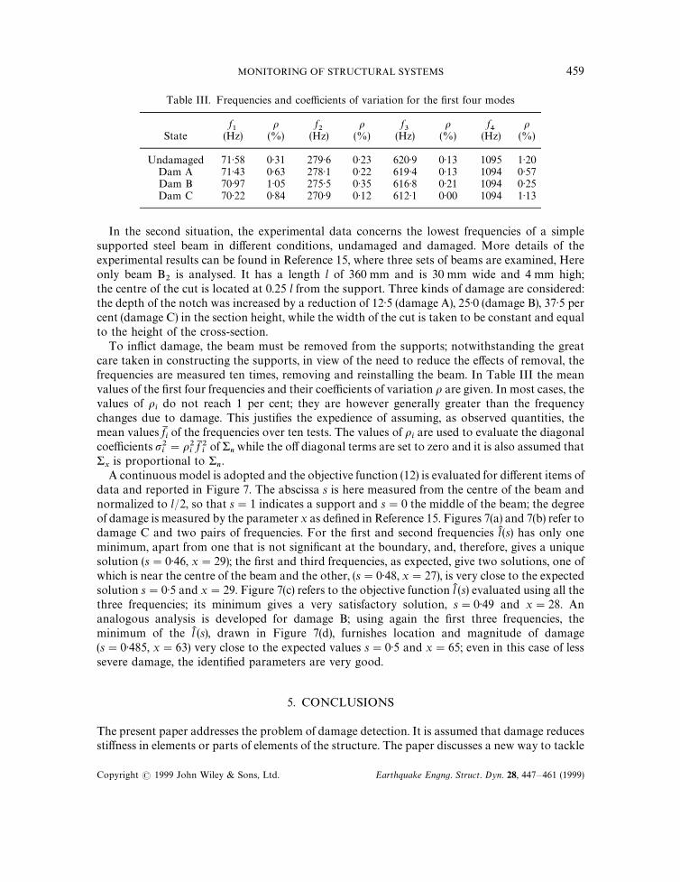
Table III. Frequencies and coefficients of variation for the first four modes
f1
o f2
o f3
o f4
oState (Hz) (%) (Hz) (%) (Hz) (%) (Hz) (%)
Undamaged 71)58 0)31 279)6 0)23 620)9 0)13 1095 1)20Dam A 71)43 0)63 278)1 0)22 619)4 0)13 1094 0)57Dam B 70)97 1)05 275)5 0)35 616)8 0)21 1094 0)25Dam C 70)22 0)84 270)9 0)12 612)1 0)00 1094 1)13
In the second situation, the experimental data concerns the lowest frequencies of a simplesupported steel beam in different conditions, undamaged and damaged. More details of theexperimental results can be found in Reference 15, where three sets of beams are examined, Hereonly beam B
2is analysed. It has a length l of 360 mm and is 30 mm wide and 4 mm high;
the centre of the cut is located at 0.25 l from the support. Three kinds of damage are considered:the depth of the notch was increased by a reduction of 12)5 (damage A), 25)0 (damage B), 37)5 percent (damage C) in the section height, while the width of the cut is taken to be constant and equalto the height of the cross-section.
To inflict damage, the beam must be removed from the supports; notwithstanding the greatcare taken in constructing the supports, in view of the need to reduce the effects of removal, thefrequencies are measured ten times, removing and reinstalling the beam. In Table III the meanvalues of the first four frequencies and their coefficients of variation o are given. In most cases, thevalues of o
ido not reach 1 per cent; they are however generally greater than the frequency
changes due to damage. This justifies the expedience of assuming, as observed quantities, themean values fM
iof the frequencies over ten tests. The values of o
iare used to evaluate the diagonal
coefficients p2i"o2
ifM 2iof &
nwhile the off diagonal terms are set to zero and it is also assumed that
&x
is proportional to &n.
A continuous model is adopted and the objective function (12) is evaluated for different items ofdata and reported in Figure 7. The abscissa s is here measured from the centre of the beam andnormalized to l/2, so that s"1 indicates a support and s"0 the middle of the beam; the degreeof damage is measured by the parameter x as defined in Reference 15. Figures 7(a) and 7(b) refer todamage C and two pairs of frequencies. For the first and second frequencies lK (s) has only oneminimum, apart from one that is not significant at the boundary, and, therefore, gives a uniquesolution (s"0)46, x"29); the first and third frequencies, as expected, give two solutions, one ofwhich is near the centre of the beam and the other, (s"0)48, x"27), is very close to the expectedsolution s"0)5 and x"29. Figure 7(c) refers to the objective function lK (s) evaluated using all thethree frequencies; its minimum gives a very satisfactory solution, s"0)49 and x"28. Ananalogous analysis is developed for damage B; using again the first three frequencies, theminimum of the lK (s), drawn in Figure 7(d), furnishes location and magnitude of damage(s"0)485, x"63) very close to the expected values s"0)5 and x"65; even in this case of lesssevere damage, the identified parameters are very good.
5. CONCLUSIONS
The present paper addresses the problem of damage detection. It is assumed that damage reducesstiffness in elements or parts of elements of the structure. The paper discusses a new way to tackle
MONITORING OF STRUCTURAL SYSTEMS 459
Copyright ( 1999 John Wiley & Sons, Ltd. Earthquake Engng. Struct. Dyn. 28, 447—461 (1999)

Figure 7. Objective function lK (s) for the supported beam, for damage B and C
the problem based on the peculiarity that damage affects only a few zones, it is frequentlyreasonable to suppose that one or at most two elements are damaged. This circumstance justifiesseparating the problem of damage detection from that of reconstruction in which the wholestiffness distribution must be determined. In this study the damaged zones are unknown but thestiffness of the structure is known to be equal to the undamaged values, except in the few damagedzones. This involves solving a large number of problems, but with a very small number ofunknowns. From this viewpoint the problems of damage identification appear simpler than thoseof reconstruction.
In accordance with numerous damage evaluation procedures in the literature, only frequenciesare assumed as modal characteristics and the identification procedure is based on the minimiz-ation of an objective function that accounts for the difference between analytical and experi-mental quantities. The use of frequencies alone cannot be sufficient for structures with relevantsymmetries; the problem, is in principle ill posed even for the simply supported beam, where thedamaged half of the beam must be known a priori.
Theoretical analysis and numerical investigations indicate that to evaluate the damage ofr elements of a discrete structure, r#1 measurements are sufficient in a noise-free situation. Forthe localization of r cracks in a continuous structure, such as a vibrating beam, at least 2rfrequencies are necessary. In any case, because only a few cracks at a time are usually detectedduring monitoring, only few measured frequencies are needed. The presence of modelling andexperimental errors, however, considerably complicate the problem to reach the exact solutionand more frequencies are required to reduce the effect of errors. The key finding remains that theinterpretative model has as unknowns, the stiffness of only r candidates among n total members.
460 D. CAPECCHI AND F. VESTRONI
Copyright ( 1999 John Wiley & Sons, Ltd. Earthquake Engng. Struct. Dyn. 28, 447—461 (1999)

The procedures developed are applied to sample cases: a supported beam, a clamped beam,a continuous beam and a shear-type frame, using experimental and simulated data. The identi-fication procedure is carried out mainly by the computer code IDEFEM, which includes a finiteelement general purpose code as a routine and performs all the steps needed to reach theminimum of the objective function.
When experimental data are used, the location of damage is always accurate, though somediscrepancies may remain in its quantification, depending on which frequencies are selected fromthose available. This highlights the sensitivity of the problem to errors and the importance ofusing reliable experimental data.
REFERENCES
1. P. Cawley and R. D. Adams, ‘The location of defects in structures from measurement of natural frequencies’, J. StrainAnal. 14, 49—57 (1979).
2. J. C. Chen and J. A. Garba, ‘Structural damage assessment using a system identification technique’, in H. G. Natkeand J. P. T. Yao (eds), Structural Safety Evaluation Based on System Identification Approach, Vieweg, Braunschweig,1988, pp. 474—492.
3. P. Hajela and F. J. Soeiro, ‘Structural damage detection based on static and modal analysis’, A.I.A.A. J. 28, 1110—1115(1990).
4. G. Hearn and R. B. Testa, ‘Modal analysis for damage detection in structures’, J. Struct. Engng. 117, 3042—3063 (1991).5. N. Stubbs and R. Osegueda, ‘Global non-destructive damage evaluation in solids’, Int. J. Anal. Exp. Modal Anal. 5(2),
67—79 (1990).6. S. H. Shen and C. Pierre, ‘Natural modes of Bernoulli-Euler beams with symmetric crack’, J. Sound »ib. 138, 115—134
(1990).7. M. H. Shen and J. E. Taylor, ‘An identification problem for vibrating cracked beams’, J. Sound »ib. 150, 457—484
(1991).8. C. Cempel, H. G. Natke and A. Ziolkowski, ‘Application of transformed normal modes for damage location in
structures’, in P. Stanley, (ed.), Structural Integrity Assessment, Elsevier Applied Science, London and New York,1992, pp. 246—255.
9. Y. Narkis, ‘Identification of crack location in vibrating simply supported beams’, J. Sound »ib. 172(4), 549—558 (1994).10. C. Davini, A. Morassi and N. Rovere, ‘Modal analysis in notched bars: tests and comments on the sensitivity of an
identification technique’, J. Sound »ib. 179(3), 513—527 (1994).11. J. R. Casas and A. C. Aparicio, ‘Structural damage identification from dynamic-test data‘, J. Struct. Engng. 120,
2437—2450 (1994).12. H. L. Chen, C. C. Spyrakos and G. Venkatesh, ‘Evaluating structural deterioration by dynamic response’, J. Struct.
Engng. 121(8), 1197—1204 (1995).13. K. G. Topole and N. Stubbs, ‘Non-destructive damage evaluation of a structure from limited modal parameters’,
Earthquake Engng. Struct. Dyn. 24, 1427—1436 (1995).14. F. Vestroni and D. Capecchi, ‘Damage evaluation in cracked vibrating beams using experimental frequencies and
finite element models’, J. »ib. Control, 2, 69—86 (1996).15. F. Vestroni, M. M. Cerri and E. Antonacci, ‘The problem of damage detection in vibrating beams’, 3rd Eur. Conf. on
Structural Dynamics, Firenze, 1996, pp. 41—50.16. G. M. L. Gladwell, ‘The inverse problem for the vibrating beam’, Proc. Roy. Soc. of ¸ondon Ser 393, 277—295 (1984).17. E. Antonacci, F. Vestroni and D. Capecchi, ‘Evaluation of damage in vibrating beam structures by means of
a nonlinear parametric estimation’, Engng. Struct. (in press).18. D. Capecchi, F. Vestroni and E. Antonacci, ‘Implementation of a procedure for identification of finite element models
from experimental modal data’, 2nd Eur. Conf. on Structural Dynamics Trondheim, 1993, pp. 593—600.
MONITORING OF STRUCTURAL SYSTEMS 461
Copyright ( 1999 John Wiley & Sons, Ltd. Earthquake Engng. Struct. Dyn. 28, 447—461 (1999)