Embed Size (px)
Citation preview

Chapter 12
MONITORING, INSPECTIONSAND FACILITY MAINTENANCE
12-1MAY 2009
Routine monitoring and inspections are essential to the successful construction and operation of a coal refuse disposal facility. Inspections, as described herein, include the components of observa-tions, testing and instrumentation measurements, as performed by a representative of the Mine Owner/Operator (Operator) in accordance with 30 CFR § 77.216-3. Personnel responsible for moni-toring and inspections require MSHA impoundment inspection training and/or qualifications and should work with a registered Professional Engineer who is familiar with the design of the disposal facility (Engineer). It is recommended that the Operator designate an Engineer to provide assistance with the implementation of design plans and specifications, assess the performance of the facility, report on the progress of the construction work, and render professional opinions regarding the conformance of construction, operation, and maintenance activities with design plans and specifi-cations. Note that the guidance in this chapter is not intended to address work-site safety issues or daily safety inspections.
Well executed monitoring and inspection programs during construction will facilitate develop-ment according to plans and specifications and aid in identifying modifications to the design that may need to be made. Routine inspections during operation of the facility allow for the identifica-tion of potential problems and resolution in a timely manner. Observations made during monitor-ing and inspections can provide a basis for either increasing or decreasing certain maintenance activities. This chapter is generally focused upon monitoring and inspection programs and their relationship to facility maintenance during development and operation of the refuse disposal facil-ity. These programs may also be required during abandonment and reclamation of a coal refuse embankment.
Monitoring and inspection requirements should be established during the design of a coal refuse disposal facility and should be documented in the Operation and Maintenance Plan, which should clearly indicate the roles and responsibilities of various parties in monitoring and inspection activi-ties. Sufficient controls should be in place so that, when monitoring and inspection is performed as specified, the intent of the design is met and satisfactory performance of the facility is achieved. Monitoring normally includes observation of work activities during facility construction, including those activities required to initially prepare the site. Monitoring may encompass such activities as visual observation, collection and analysis of quality control samples, performance of field and labo-ratory testing, evaluation of construction methods, collection and review of instrumentation readings and evaluation of survey data.

12-2
Chapter 12
MAY 2009
Inspections for evaluating performance are typically conducted for the overall facility and at areas that have been recently constructed. These inspections normally include visual observations; collec-tion of physical data, instrument readings and flow rate measurements (if applicable); and evalua-tion of the assimilated data. Photographing of site conditions, during construction and operation, is an excellent way to document site conditions and any changes in conditions and is a recommended practice. Information from previous inspections and monitoring activities should be reviewed and compared to current data and plotted instrumentation data so that an informed evaluation can be made. In accordance with 30 CFR § 77.216-3, facility inspections for impounding refuse facili-ties must be performed on a 7-day basis unless otherwise approved by the MSHA District Man-ager. Annual reporting and certification requirements for impoundments are provided in 30 CFR § 77.216-4. Additionally, some states have inspection, reporting, and certification requirements that differ from the federal requirements. Annual dam safety inspections may be required by some state regulatory agencies, but these can generally be combined with the MSHA annual reporting and certification requirements.
It is recommended that monitoring and inspections generally be performed under the guidance of a registered Professional Engineer who is familiar with the design (including safety criteria for the structure) and involved in the implementation of the construction plans and specifications. Thus, this individual can prepare required reports and certifications and can assess: (1) conformity with the approved design, (2) significance of the instrumentation records, (3) potential conditions that may warrant notification of agencies including MSHA, and (4) design modifications and remedial construction activities that may be needed. Typically, the design engineer performs or contributes to this activity. In describing the monitoring and inspection activities in this chapter, and particularly actions that may be in response to observed conditions, test results, or instrumentation readings, reference is made to the Engineer in situations that are typically important for such an individual to assess and determine subsequent action. The Engineer’s involvement in other activities may also be important, and the site-specific Operation and Maintenance Plan should cite monitoring and inspec-tion requirements. By maintaining the involvement of a registered Professional Engineer who is thor-oughly familiar with the design during construction and operation, the mine operator is in position to assess conformity with the approved plan and to respond to regulatory agencies regarding perfor-mance or compliance concerns.
If potentially hazardous conditions develop, MSHA requires under 30 CFR § 77.216-3 that the Opera-tor take action to: (1) eliminate the condition, (2) notify the District Manager, (3) notify and prepare to evacuate miners who may be affected, and (4) perform inspections on an eight-hour or more frequent basis. The Engineer should be a source of technical advice in such situations. Potentially hazardous conditions can be identified based on criteria established for Emergency Action Plan preparation, as discussed in Chapter 14.
Facility maintenance includes routine recurring actions for establishing vegetation and controlling ero-sion, periodic actions after unusual events such as clearing debris, and long-term actions in response to deterioration of structures, such as repair of channel linings and maintenance of embankment slopes. Monitoring and inspections may identify conditions that are inconsistent with the Operation and Maintenance Plan because of differing site conditions, construction procedures, or performance. In such situations, new maintenance requirements may need to be developed.
12.1 MONITORING AND INSPECTIONSThere is an inherent degree of uncertainty in the engineering design of a refuse disposal facility that can normally be offset by applying factors of safety in analytical procedures and by using conserva-tive estimates of material properties. Engineers, particularly in the geotechnical fields, have devel-oped observa tional/monitoring procedures to deal with these uncertainties without being overly

12-3
Monitoring, Inspections and Facility Maintenance
MAY 2009
conservative. The following is a brief listing of the purposes for monitoring and inspection and the basis for their incorporation into refuse disposal facility development:
• Construction quality can vary depending on the specific activity, site conditions, equipment and personnel, all of which can affect facility performance. Monitoring and inspection provide a means of controlling adherence to design requirements and documenting construction quality.
• Geologic conditions can vary significantly at a site. These variations can be accom-modated by monitoring and inspection programs during construction and the use of reasonable factors of safety in the design. Monitoring during construction enables evaluation of the validity of design assumptions and analyses and provides an opportunity to make changes as needed.
• Because it is impractical to investigate all natural conditions at a site or anticipate every aspect of facility operation, confirmation of design assumptions through moni-toring and inspection can offset limitations in site exploration.
• The long operating life of a refuse disposal facility can lead to many changes in site conditions. For example, changes in coal cleaning procedures and refuse characteristics may occur due to mining of different coal seams during the operational period. An effective monitoring and inspection program can identify when significant changes are occurring or performance problems are developing, so that appropriate modifications can be made quickly when implementation is least difficult and expensive.
• Monitoring and inspection programs form the basis for determining when routine main-tenance is needed in order to limit the deterioration of important facility components.
Monitoring and inspection rely heavily on visual observation and are supported by quality control testing, instrumentation, and engineering evaluation. The complexity of a monitoring program can range from simple visual examination of surface conditions to sophisticated surveys using electronic equipment. The simplest means are usually the most effective, especially for the constantly changing conditions associated with coal refuse facilities. A more complicated monitoring and instrumentation program may be justifiable when the information obtained can result in an improved design, opera-tion or significant savings in construction costs. Regardless of complexity, a monitoring program is successful only if the information obtained is pertinent to the design and operation and the data are accurate and measured, recorded and properly interpreted by qualified persons in a timely manner. Accordingly, any monitoring program must be based on knowledge of design requirements, and the observations and measurements must be obtained and interpreted by staff cognizant of the purpose for and limitations of the instrumentation.
12.1.1 Monitoring and Inspection ObjectivesImportant objectives for monitoring and inspection at coal refuse facility sites include the following:
• Validating the assumptions upon which the design was based – A valuable function of monitoring programs is to provide data for verifying that the assumptions upon which the facility design is based are valid. Therefore, it is critical that monitoring data be evaluated by an engineer who is thoroughly familiar with the design and associated engineering analyses and assumptions and who is responsible for certifi-cation of the work.
• Providing data for improving construction methods –As an example, the compac-tion equip ment being used at a site may produce an undesirable particle compaction arrangement that, in turn, affects properties such as strength or hydraulic conduc-

12-4
Chapter 12
MAY 2009
tivity. Through observation of embankment construction, changes can be made in equipment selection, traffic routing, drying or wetting, or other factors such that the desired results are achieved.
• Providing a means for early detection of potential problems or areas requiring main-tenance or remedial improvement – A field monitoring and inspection program can identify problems before conditions deteriorate to the point that extensive repair is required or failure can occur. The natural variability of earthen and coal refuse ma-terials may result in unexpected deviations from the original design. Changes in the rate of refuse placement could alter embankment elevations and pool levels, affect-ing embankment stability.
A project-specific failure modes analysis can be useful in establishing site-specific monitoring and inspection objectives, particularly for facilities with impounding embankments (Martin and Davies, 2000). Through an objective review of potential modes of failure of the disposal facility, considering all loading conditions and design features, the most important monitoring, instrumentation, and in-spection objectives can be identified. Martin and Davies suggest the following process:
• Identification of potential failure modes and corresponding warning signs.• Evaluation of how quickly failure could occur and how potential problems could be
detected before they develop into incidents.• Critical assessment of how likely it is that warning signs will be detected, recog-
nized, reported and acted upon.• Identification of instrumentation types and locations that provide the most relevant
monitoring data.• Evaluation of the significance of data trends as opposed to single measurements/ob-
servations.• Evaluation of the value of establishing acceptable parameter limits or other limiting
criteria.• Review of lines of responsibility and communication.• Review of data management, interpretation, action plans, and reporting.
Figure 12.1, as modified from Martin and Davies (2000), illustrates the relationship of failure modes, warning signs, and surveillance measures for tailings dams.
12.1.2 Visual ObservationsThe simplest, but often most valuable, monitoring method is visual observation by experienced per-sonnel of important facility components and the surrounding area on a schedule compatible with site activity and the rate at which the facility configuration is changing. The required frequency for obser-vations and the level/knowledge of the individual performing the observations should be established by the designer and should be consistent with federal and state requirements. The following should be considered when developing a schedule for visual observations:
• The type of refuse facility (impounding or non-impounding) and stage of construction. • Specific critical construction items (e.g., internal drains, surface channels, decant
pipe, cut-off trench) that should be observed.• Specific operational areas or items (e.g., spillway operation) required for evaluating
performance and potential design modification.
• Identification of components/areas that require only periodic monitoring and inspec-tions and their frequencies.

12-5
Monitoring, Inspections and Facility Maintenance
MAY 2009
Components/items to be observed depend upon the facility configuration. Typical factors include:
• Facility configuration and type of refuse disposal• Geotechnical design requirements• Site mining and foundation requirements• Appurtenant hydraulic facilities (spillways or decant pipes)• Environmental control provisions• Construction procedures
FIGURE 12.1 FAILURE MODES, WARNING SIGNS AND SURVEILLANCE MEASURES
LOSS OF DIVERSIONS/ SPILLWAY FLOW CAPACITY
LOSS OF CREST ELEVATION
INTERNAL EROSION OF DAMFILLS
INTERNAL EROSIONOF FOUNDATIONMATERIALS ORPIPE BACKFILL
SURFACE EROSION OF DAM SLOPES
SLIDE THROUGHDAMFILL AND/OR
FOUNDATION
BREAKTHROUGH OF TAILINGS INTO MINE
BLOCKAGE/FAILURE OFDIVERSIONS/SPILLWAY
GRADUAL INFILLING OF DIVERSIONS
TAILINGS POND LEVEL SETTLEMENT
CHANGE IN CRESTGEOMETRY/CRACKING
CHANGE IN SLOPEGEOMETRY (US/DS)/ CRACKING
CHANGE IN SEEPAGECONDITIONS/LOCATIONS/ VEGETATION
SINKHOLES, TURBID SEEPAGE DISCHARGE
GRADUAL TREND TOINCREASED TURBIDITY IN SEEPAGE
SEEPAGE INDUCED SLOUGHING IN
EMBANKMENT
RAISED SATURATION LEVELS, SOFTGROUND CONDITIONS
LARGE, SUDDEN CHANGES INPIEZOMETRIC LEVELS
LARGE, SUDDEN CHANGES INSEEPAGE FLOWRATES
LONG-TERMPIEZOMETRIC CHANGES
LONG-TERM INCREASE INSEEPAGE FLOWRATES
LARGE, SUDDENMINE DISCHARGES
INSPECTIONS OFDIVERSION/SPILLWAYS
TAILINGS POND LEVEL CHECKS ANDPERIODIC SOUNDINGS
REQUIRED CRESTELEVATION VERSUSDECANT ELEVATION
SURFACE MONUMENT SURVEYS
PIEZOMETERS/WELLS
INCLINOMETERS/SETTLEMENT GAGES/ EXTENSOMETERS
SEEPAGE WEIRS
INSPECTION OF DAM SLOPES/CREST/DOWNSTREAM TOE
SEEPAGE WATERQUALITY/TURBIDITY
CLOGGING OF TOEDRAINS/OXIDATION PRODUCTS
INSPECTION OF ABUTMENTS
INSPECTION OFMINE DISCHARGE
OVERTOPPING
MASSMOVEMENT
INTERNALEROSION
SURFACEEROSION
MINESUBSIDENCE
FREEBOARDLESS THAN
DESIGN CRITERIA
TAILINGS DAMFAILURE MODES
ADVERSECONDITIONS
RAPID WARNING SIGNS
GRADUALWARNING SIGNS
SURVEILLANCE MEASURES
DECANT PIPELINE INSPECTIONS
MINE DISCHARGEDOESN’T CORRELATE
TO RAINFALL
TAILINGS LEVELRISING FASTER
THAN ANTICIPATED
LOSS OF UPSTREAM EROSION PROTECTION
(ADAPTED FROM MARTIN AND DAVIES, 2000)
FIGURE 12.1 FAILURE MODES, WARNING SIGNS AND SURVEILLANCE MEASURES
FIGURE 12.1 FAILURE MODES, WARNING SIGNS AND SURVEILLANCE MEASURES

12-6
Chapter 12
MAY 2009
Checklists should be developed for each refuse disposal facility and should be incorporated into the Operation and Maintenance Plan. These checklists should be used in conjunction with the facility plans and specifications. Figure 12.2 presents an example of a data collection form that is incorporated into a site as-built drawing with topographic contours. The combination of the data collection form and as-built drawing provides a good point of reference during monitoring activities and allows areas of concern to be marked without the need for cumbersome descrip-tions/text. Items such as density test locations, seeps, sloughs, erosion and slurry discharge loca-tion can easily be indicated on the drawing.
FIGURE 12.2 EXAMPLE DATA COLLECTION FORM
SCALE
400 4000
FIGURE 12.2 EXAMPLE DATA COLLECTION FORM
FIGURE 12.2 EXAMPLE DATA COLLECTION FORM

12-7
Monitoring, Inspections and Facility Maintenance
MAY 2009
Table 12.1 is a generic list that covers most aspects of refuse disposal facility activity. This list can be used as the basis for development of a site-specific data collection form. Other available references include the MSHA Coal Mine Impoundment Inspection and Plan Review Handbook prepared by MSHA (2007) and the Guidance Document for Coal Waste Impoundment Facilities & Coal Waste Impoundment Inspection Form prepared by the West Virginia Water Research Institute (2005).
Extensive digital photography is recommended for documenting visual inspections of a coal refuse disposal facility. Photographs not only document the observations made during monitoring or inspection activities, but they can also be used later to track the construction progress of the facility. Photographs are also invaluable for comparing how conditions such as seepage areas change over time. The location and/or orientation of the camera for each photograph should be documented on the as-built drawing or data collection form.
Hand-held global positioning system (GPS) units are very useful for locating items of interest. Most hand-held GPS units can provide position location to within about 10 feet. For most refuse facilities, this accuracy is sufficient for locating sampling or testing locations, wet areas, minor seeps, or other non-critical items. The use of a hand held GPS unit or altimeter unit for elevation determinations is not currently recommended due to lack of accuracy. It should be noted that the GPS coordinates may not conform to the coordinate system used by the mine. Software for performing coordinate conver-sions is available form commercial vendors.
12.1.2.1 Schedule and Checklist for Visual (and Other) ObservationsA schedule for observations should be provided in the Operational and Maintenance Plan. The sched-ule of observations must be compatible with federal and state regulatory agency inspection require-ments. In accordance with 30 CFR § 77.216-3, inspections (not to exceed 7-day intervals) are required for all impounding facilities meeting the requirements of 30 CFR § 77.216(a). Section 12.3 provides additional details relative to embankment/impoundment safety inspections. The recording of data or collection of measurements from installed instrumentation should also be defined in the schedule of observations. Chapter 13 provides additional details concerning the types of instruments available and information related to their installation and use. While 7-day visual inspections are required, continuous monitoring may be appropriate for some critical construction activities (e.g., structures that are ultimately buried, such as decant pipe and internal drain installations, instrumentations, etc.). Alternate frequencies (more or less frequent than every 7 days) for instrumentation monitoring may be desirable.
Inspection of impounding embankments during and after significant precipitation events is recom-mended. This is a good time to observe the operation of decant and spillway facilities and the outlets to internal drains and to verify that they are functioning properly. Special attention should be paid to whether flow is unobstructed and erosion protection, especially at outlets, is functioning properly.Another important time to observe the operation of a dam is during first filling. The first time the foun-dation and embankment are subjected to seepage pressures and the first time that flow occurs through, and possibly along, conduits, is an important time to verify that performance is acceptable. Slurry impoundments are constructed over a long period of time and are filled as they are constructed. Special attention should be paid when the saturation level reaches the level of new features, such as conduits.A schedule for observations should be developed for each major aspect of construction of a refuse disposal facility, including:
• Initial site development• Liner installation (if applicable)• Starter dam/embankment construction• Refuse embankment construction

12-8
Chapter 12
MAY 2009
• Instrumentation installation and data measurement• Appurtenant hydraulic facility construction• Backfill and abandonment of impoundments• Mine barrier, bulkhead and seal construction, if applicable
To be most useful, the checklist/data collection form presented in Table 12.1 should be tailored to site conditions. The completed data collection form/checklist (e.g., Figure 12.2) should be regularly reviewed by the Engineer. In addition to descriptions of the conditions observed, deviations from the plans and specifications should also be indicated on the form and should be reported to responsible facility personnel (Engineer, Contractor, and Operator).
12.1.2.2 Facility Development
12.1.2.2.1 Site PreparationSite preparation includes activities such as clearing and grubbing, topsoil/subsoil stockpiling, foun-dation preparation, and liner installation. These items relate to both initial facility development and facility expansion and are typically performed as individual construction activities rather than as a part of ongoing operations. A brief summary of typical observations associated with site preparation is provided in the following:
• Clearing and grubbing – Clearing and grubbing typically includes removal of unsuitable materials such as trees, tree stumps and roots, brush and other vegetation. Important items related to clearing and grubbing that should be observed and noted include: location and extent, adequacy of vegetation removal, debris disposition, and identification of unanticipated and/or suspect conditions (e.g., mine openings, landslides).
• Topsoil/subsoil stockpiling – Important items associated with topsoil/subsoil stockpiling that should be noted include: location and extent, drainage control provisions, depths removed, location and configuration of stockpiles, identifica-tion of unanticipated conditions (e.g., landslides, springs, potential for additional soil removal). Areas where the planned embankment and impoundment are to be located should be observed, particularly where soils have been excavated, to deter-mine potential natural seepage conditions that may not have been evident before disturbance.
• Foundation preparation – Important items associated with foundation preparation that should be noted include: location and extent of work areas; preparation work performed prior to placement of any refuse materials (removal of unsuitable mate-rial, proof-rolling, slope modification and removal of rock overhangs, spring col-lection and underdrain installation, etc.); installation of cutoffs, keys or benches in preparation for refuse placement; and construction of mine barriers or bulkheads.
• Liners – If liners are required, the important items to be noted include: materials (natural or synthetic including properties), thickness placed, compaction (equipment type, tests), performance observations (firm or pumping), and cover protection (soil, vegetation, refuse).
12.1.2.2.2 Starter Embankment and Internal DrainsFollowing site preparation, construction of a starter embankment using borrow material (soil and rock) or coarse refuse is the first step in preparing a disposal facility site for ongoing refuse dis-posal. Starter embankments may be zoned or homogeneous. Important items to be observed include

12-9
Monitoring, Inspections and Facility Maintenance
MAY 2009
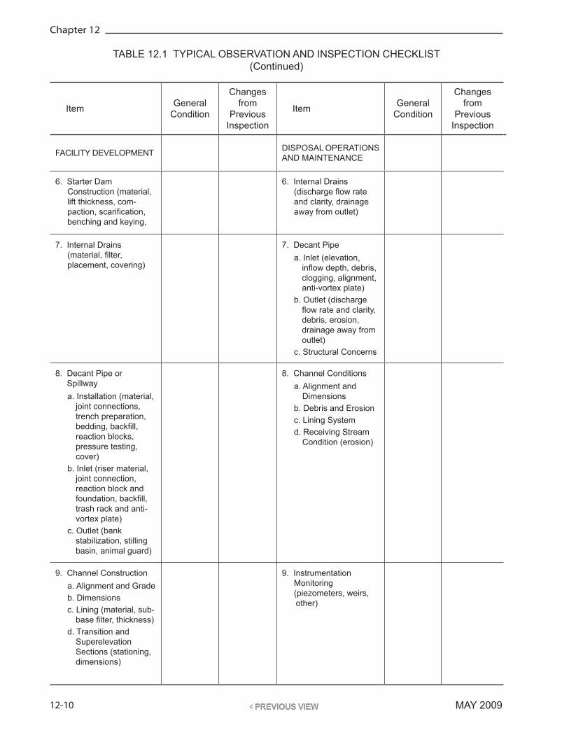
TABLE 12.1 TYPICAL OBSERVATION AND INSPECTION CHECKLIST
Item General Condition
Changes from
Previous Inspection
Item General Condition
Changes from
Previous Inspection
FACILITY DEVELOPMENT DISPOSAL OPERATIONS AND MAINTENANCE
1. Erosion and Sediment Controlsa. Diversion Ditchesb. Silt Fencesc. Sediment Trapsd. Sediment Ponds
1. Stage of Construction and Refuse Placement
(lift thicknesses, com-paction, scarification, benching)
2. Clearing & Grubbing 2. Working Surface and Area Maintenance (survey control, grading and drainage control). Refuse Placement (lifts, compaction, scarification, benching)
3. Topsoil/Subsoil Stockpiling
3. Embankment Crest and Benches
a. Alignment and Grade
b. Evidence of Movement (cracks, sloughs, scarps)
c. Abutments (benching, drainage control, erosion)
d. Crest low point elevation
4. Foundation Preparation a. Removal of
Unsuitable Material b. Collection of Springs c. Underdrain
Installation d. Benching, Cut-off or
Keyway Const. e. Sealing of Mine
Entry Bulkheads and Barriers
4. Embankment Slopes a. Alignment and
Slope b. Seepage (flow
rates, clarity) c. Slope Movement
(scarps, sloughs, bulging)
d. Erosion e. Vegetation f. Burning or
combustion
5. Liner Construction (material, thickness, compaction, cover)
a. Soil b. Geomembrane c. Geosynthetic Clay
Liner d. Other
5. Liner, Foundation and Abutment Conditions
a. Drainage Control b. Erosion c. Concentrated
Seepage or Boils
12-10
Chapter 12
MAY 2009
Item General Condition
Changes from
Previous Inspection
Item General Condition
Changes from
Previous Inspection
FACILITY DEVELOPMENT DISPOSAL OPERATIONS AND MAINTENANCE
6. Starter Dam Construction (material, lift thickness, com-paction, scarification, benching and keying,
6. Internal Drains (discharge flow rate and clarity, drainage away from outlet)
7. Internal Drains (material, filter, placement, covering)
7. Decant Pipe a. Inlet (elevation,
inflow depth, debris, clogging, alignment, anti-vortex plate)
b. Outlet (discharge flow rate and clarity, debris, erosion, drainage away from outlet)
c. Structural Concerns
8. Decant Pipe or Spillway a. Installation (material,
joint connections, trench preparation, bedding, backfill, reaction blocks, pressure testing, cover)
b. Inlet (riser material, joint connection, reaction block and foundation, backfill, trash rack and anti-vortex plate)
c. Outlet (bank stabilization, stilling basin, animal guard)
8. Channel Conditions a. Alignment and
Dimensions b. Debris and Erosion c. Lining System d. Receiving Stream
Condition (erosion)
9. Channel Construction a. Alignment and Grade b. Dimensions c. Lining (material, sub-
base filter, thickness) d. Transition and
Superelevation Sections (stationing, dimensions)
9. Instrumentation Monitoring (piezometers, weirs,
other)
TABLE 12.1 TYPICAL OBSERVATION AND INSPECTION CHECKLIST(Continued)

12-11
Monitoring, Inspections and Facility Maintenance
MAY 2009
Item General Condition
Changes from
Previous Inspection
Item General Condition
Changes from
Previous Inspection
FACILITY DEVELOPMENT DISPOSAL OPERATIONS AND MAINTENANCE
10. Instrumentation (survey monuments, piezometers, weirs, other)
10. Reclaimed Slopes (vegetation development and control, drainage control, erosion, seepage)
11. Reclamation a. Grading and
Stabilization b. Soil and Topsoil
Cover c. Revegetation
(fertilizing, seeding, mulching)
d. Seepage Control (collection, conveyance, treatment)
11. Impoundment and Slurry Deposition
a. Abutment Slopes (erosion, instability)
b. Water Level and Control (decant inlet, pumping, other)
c. Slurry Line Alignment and Discharge Location
c. Fines Deposition (location, distri-bution, delta areas, percent exposed/above pool level)
ADJOINING AREAS
1. Foundation and Abutment Conditions
2. Upstream Watershed3. Downstream
Inundation Area
OTHER DEVELOPMENT (Work unrelated to the disposal facility)
1. Within Facility Watershed (potential for increased runoff or landslides)
2. Downstream of Facility (potential to change hazard classification)
3. Within Facility
Note: Reference should be made to a design or as-built plan drawing.
TABLE 12.1 TYPICAL OBSERVATION AND INSPECTION CHECKLIST(Continued)

12-12
Chapter 12
MAY 2009
materials placed, lift thickness and compaction (including density and moisture testing), preparation (scarification) of compacted surfaces before placement of subsequent lifts, and benching of new lifts into adjoining abutments or embankment slopes, etc.
Internal drains are frequently part of starter embankments, and typical observations include: mate-rials used for the drain and filter system, installation conditions (trenched into embankment or constructed on completed lift), placement of drain materials (susceptibility to segregation and con-tamination during placement and spreading) including geotextiles, drain dimensions and grade, and details for covering the completed installation to protect the drain from erosion.
12.1.2.2.3 Decant PipesDuring installation of decant pipes, the following observations should be recorded: alignment and grade, pipe material and joint connections, corrosion protection (where applicable), installation details (trench configuration), bedding and backfill (materials used and compaction, including density and moisture testing results), seepage control measures (location, dimensions and mate-rials), location and configuration of reaction blocks at changes in alignment and grade, results of pressure testing, and details related to covering of the completed installation and protecting the conduit from damage by heavy equipment traffic. The adequacy of placement of backfill in the haunch area should be given special attention. Details related to the following should be observed for decant inlets: riser configuration and materials, joint connections, foundation and reaction block, riser backfill and compaction, inlet trash rack and anti-vortex plate. For decant outlets details related to the following should be noted: receiving channel bank stabilization or stilling basin, drainage control to preclude backup of water into pipe, and animal guard.
12.1.2.2.4 Channel ConstructionChannels may include emergency spillways, decant outlets, diversion ditches, groin or perimeter ditches, haul and access road ditches, and bench gutters. Prior to construction, the upland areas should be observed for evidence of instability that may adversely impact planned excavations. Impor-tant observations to be recorded for channels during construction include: alignment and grade, dimensions (width, depth, side slopes), erosion-protection lining (sub-base, filter, lining thickness and material), and details of transition and superelevation conditions at changes in alignment, slope or section (stationing and dimensioning).
12.1.2.2.5 InstrumentationInstrumentation is sometimes installed during starter embankment construction. Additional instrumentation is also generally installed during facility expansion. This instrumentation may include survey monuments, piezometers, weirs, and other devices, as discussed in Chapter 13. Important observations to be recorded may include: instrument type, material, make and model; installation details (materials, dimensions); the results of initial calibration and verification of function; and the results of periodic testing to verify continued performance. Maintenance should also be regularly performed as required by the type of instrument (Section 13.5). For example, peri-odic flushing of piezometers, if subject to fines accumulation, and regular cleaning of weir boxes are important.
Instruments need to be read in a consistent fashion such that the results are not affected by the indi-vidual taking the reading and are directly comparable. If necessary, specific instructions should be provided relative to collecting and recording instrumentation data.
12.1.2.2.6 ReclamationAny areas that are covered with soil and/or vegetated should be noted by location and include a description of the work undertaken. Where areas are covered, the source of the soil or topsoil,

12-13
Monitoring, Inspections and Facility Maintenance
MAY 2009
the thickness of the cover, and the method used to place and/or compact the material should be noted. Where areas are vegetated, the type of seeding used, the method of placing the seeding, any amendments added, and procedures used to protect the vegetation, such as mulch or straw should be noted.
12.1.2.3 Adjoining Area ConditionsAreas adjoining a refuse disposal embankment include downstream areas, embankment abutments and upstream areas. Each of these areas should be carefully observed for the presence of conditions that could impact embankment stability, such as concentrated seepage, and other aspects of facility operation and safety, as discussed in the following subsections.
12.1.2.3.1 Sloughing or SlidingStability of an embankment is dependent not only upon conditions within the embankment itself, but also upon the embankment foundation materials. Therefore, areas immediately upstream and down-stream from any embank ment should be inspected for bulging conditions, open cracks with vertical displacement or other signs, such as the orientation of cracks, that could indicate movement of the soil or rock materials is occurring. In wooded areas, a possible means of identifying the presence of such conditions is to observe the trunks of the trees to determine if a group of trees has an unusual inclination. If such signs are evident immediately adjacent to an embankment, the embankment sur-face should be examined very carefully to see if the movement has extended into the embankment.
12.1.2.3.2 Signs of SubsidenceEvidence of mine subsidence can include surface cracks (particularly when oriented with mine work-ings and/or vertical displacement), depressions, and sinkholes. Often evidence of subsidence due to underground mining is more readily apparent on natural ground surfaces than on an embankment surface, because the embankment can arch over a subsided area for some period of time or the sub-sidence features can be hidden by disposal operation. Subsidence that occurs on the natural landform can cause rapid changes in contours where bedrock is shallow or sinkhole development where water washes material into the mine. Also, in areas where subsidence is not uniform, the inclinations of tree trunks can vary significantly over short distances. If possible signs of subsidence are observed, mine maps should be reviewed to determine if there are mine works present that could be causing the problem. Subsidence may also occur over mines that are unmapped or incompletely or inaccurately mapped. In many cases, small punch mines have been developed for residential coal consumption and may not be mapped, as is done for commercial coal mines. The lack of availability of maps should not be considered as evidence of the absence of underground mines.
12.1.2.3.3 Evidence of ErosionConditions where erosion of the natural ground surface occurs downstream or downslope from an embankment, or erosion of the embankment itself, can be critical and includes cases where: (1) an adjacent stream rises during a flood causing erosion of the embankment toe or (2) the drain-age system from areas upstream of the embankment discharges onto or immediately adjacent to the embankment causing downcutting and eventual instability. The locations of any areas of sig-nificant increase in erosion of the embankment or the adjacent ground surface should be noted.
12.1.2.3.4 Springs or Seepage AreasInstability of an embankment slope due to high pore-water pressures or piping of soil materials can occur in the embankment foundation and abutments as well as on the downstream face of the embankment. Therefore, it is important to observe the downstream slope and area downstream from the abutments and toe of an embankment and to note development of new seepage areas or changes in areas where seepage was previously occurring. In particular, it should be deter-

12-14
Chapter 12
MAY 2009
mined whether existing seepage zones have increased in flow volume since the last observation and whether the seepage is carrying fines, which is an indication of internal erosion.
The presence of “boils” (points where a concentrated upwelling of seepage is creating a deposit of fine material) is an especially important indicator of internal erosion. Records of spring and seep-age area flow volume should be kept for comparison purposes. Significant changes in seepage or evidence of internal erosion should be brought to the attention of the Engineer, because corrective measures to prevent instability, progressive internal erosion, or piping may be warranted. Seepage and water quality monitoring (e.g., temperature, turbidity, and total dissolved solids) and interpre-tation of trends are discussed in Pelton (2000).
12.1.2.3.5 Changes in VegetationAs noted previously, changes in the inclination of tree trunks can indicate sliding and sloughing of the natural ground materials or subsidence due to underground mining. Also, areas that have either an abnormal amount of dying vegetation or unusually dense vegetation may indicate the presence of seepage zones that are not immediately evident at the ground surface.
12.1.2.4 Other Development Work
12.1.2.4.1 Upstream DevelopmentAny changes in the watershed area above the facility, such as tree cutting, strip mining, and residen-tial or industrial development should be noted, since these activities could affect runoff flows to the site. Also, these activities may affect the quality of surface water passing through the site, which could mistakenly be attributed to the refuse disposal facility. The location and extent of upstream changes and the nature of such changes should be documented and brought to the attention of the Engineer.
12.1.2.4.2 Downstream DevelopmentInundation mapping associated with dam breach analysis for establishing the hazard potential classi-fication is based upon topography and stream conditions downstream from the refuse impoundment. Future development in the downstream floodplain could increase the hazard potential rating. Also, a new mine opening or coal preparation plant constructed downstream from the facility spillway might be susceptible to flooding during large storms. Any such change in downstream land use, including the location and description of the change, should be brought to the attention of the Engineer.
12.1.2.4.3 Disposal of Materials Other than Coal RefuseThe design of critical portions of refuse disposal facilities is typically based on the assumption that uniform materials will be used. The use of materials from other sources (e.g., power plant waste) or from site development work unrelated to the disposal facility, such as placement of coarse-grained rock from slope excavations in the disposal facility embankment, could cause undesirable behavior and should not be permitted unless specifically allowed in the approved design plan. Material that could lead to combustion in the coal refuse embankment is not permitted.
12.1.2.5 Refuse Disposal Operations and Maintenance
12.1.2.5.1 Refuse Placement and CompactionDisposal operations comprise the placement of refuse materials within embankments in accordance with the plans and specifications. Important observations to be documented include: materials (gra-dation and moisture), delivery to site and spreading (location and equipment), lift thickness, com-paction (equipment, number of passes), surface conditions (firm, pumping), surface preparation or scarifying (method or equipment, extent and frequency), and benching of new lifts into embank-ment and abutment materials (dimensions and extent). During inclement weather, it can be difficult

12-15
Monitoring, Inspections and Facility Maintenance
MAY 2009
to meet construction specifications for refuse placement and compaction, particularly in structural zones, and documentation of potential problem areas is important to the planning of future actions. Where feasible and appropriate, other zones or areas that can accommodate coal refuse where place-ment standards are lower, such as during inclement weather, may be provided as part of the design. Monitoring and inspection of these areas typically include observation of lift thickness, grading, access, and drainage control.
12.1.2.5.2 Working Surface MaintenanceThe working surface where active refuse disposal is taking place should be maintained consistent with the plans and specifications and with careful control of drainage. Observations should include: (1) survey control such as stakes or markers to define placement limits and grades, (2) lift placement and compaction, (3) scarification of the surface of layers that are too smooth to properly bond to the next layer, and (4) drainage control measures for directing water away from active placement areas and toward collection ditches. Density and moisture content testing must be fully documented including the location of the tests (which should generally be random or focused on areas of suspect compaction), the lift thickness, and the test results. Compaction conditions should be further evalu-ated if the test results show that the compaction specifications are being met, but the lift surfaces after compaction remain soft or spongy. If the compaction specifications are not met, then additional compaction will be required and, if this situation occurs frequently, the cause should be determined.
Adequate compaction requires the proper lift thickness and number of passes of the compaction equipment be used. The type and number of passes required for achieving the minimum compaction specifications will depend on the compaction equipment and lift thickness. When new or different compaction equipment is used, the number of passes needed to meet the compaction specifications needs to be established by a coordinated program of field density testing. The compaction operation should be observed to verify that lifts are being systematically compacted at the proper thickness with overlapping passes of the compaction equipment.
12.1.2.5.3 Embankment Crest ConditionsThe crest of a refuse embankment should be constructed and maintained in conformance with the facility plans and specifications and should be generally level (or with a slight slope towards the impoundment) to provide adequate freeboard and drainage control. Important observations include: (1) alignment and level, (2) indications of movement (e.g., cracks, sloughs, scarps), and (3) abutment interface (including benching to tie refuse materials into natural hillsides, control of drainage from hillsides, and control of erosion).
Coal refuse tends to break down when exposed to the elements and to equipment traffic. When a crest elevation is maintained for a period of time, a layer of highly compacted and weathered mate-rial may be present at the surface. Prior to raising the crest, this material should be disturbed by thorough scarification or should be removed so that it does not create a continuous horizontal layer of low hydraulic conductivity within the embankment. Such a layer can cause elevated seepage levels in the embankment and defeat the purpose of internal drainage measures.
12.1.2.5.4 Embankment Slope ConditionsThe slopes of a refuse embankment should be developed and maintained in conformance with the facility plans and specifications. Temporary slopes should be consistent with the geometry and over-all development shown in the design report. Documentation should include alignment and steep-ness, seepage, movement, and erosion. The following conditions should be noted, as applicable:
• Sloughing and sliding – All embankment slopes should be carefully inspected for the possible presence of sloughing and/or sliding. Such conditions are usually accom-

12-16
Chapter 12
MAY 2009
panied by bulging at or along the bottom of the distressed area and possibly the formation of a vertical displacement (scarp) and cracking at or along the top of the distressed area. Special care is required in areas of heavy vegetation to avoid over-looking these areas of distress. Heavy vegetation that hampers inspection activities should be cut or removed, as should any trees that begin to grow on the embank-ment. Particular attention should be paid to the downstream slope of an impounding embankment. Any signs of sliding or sloughing should be reported immediately to the Engineer and Operator.
• Subsidence – Subsidence of an embankment can occur as a result of three conditions: (1) the collapse of voids in the embankment or foundation that form due to piping, when seepage flows remove particles of refuse or soil, (2) consolidation of soft foundation or embankment materials, and (3) collapse of mine workings. Subsidence due to piping can usually be recognized by the presence of localized bowl-shaped depressions at the surface. Subsidence due to settlement of soft foundation materi-als usually results in low areas on the embankment surface and occasionally cracks. Subsidence due to under ground mining can be identified by cracking along straight lines, typically parallel to the primary direction of mining, or as deep circular sink holes. When vegetation is tall, care should be taken to avoid overlooking such signs of distress. If subsidence is discovered, the size, shape and extent of the distress should be determined and recorded. Any evidence of subsidence should be reported immediately to the Engineer and Operator.
• Erosion – Erosion is loss of ground cover caused by a lack of proper drainage control. Sheet erosion is a surficial loss of soil or refuse in a more or less uniform pattern extending over wide areas. Gully erosion is the result of concentrated overland flow and leads to the creation of narrow and possibly deep channels in the ground surface. Any occurrence of erosion should be documented as to type, location, and extent. Erosion should be corrected when it starts to develop and before it becomes significant. Erosion that has progressed to deep gullies can affect seepage and stability and is much more difficult to correct. If erosion is found to concentrate or recur in particular areas, consideration should be given to improv-ing surface drainage in those areas.
• Moisture conditions, springs, seeps and wet areas – Slopes should be monitored for the presence of springs, seeps and wet or boggy areas. Evidence of such condi-tions includes the presence of unusually wet and/or soft areas and areas where snow melts rapidly in the winter. Also, vegetation may be thriving due to the moist conditions, leading to unusually dense and taller growth as compared to surround-ing vegetation, or vegetation may be adversely affected by acidic seepage and may be discolored or dying. The location and the extent of such conditions should be documented. If actual flow is observed, the rate of flow should be measured or estimated, and the quantity and character of any suspended solids (silt, sand, etc.) carried by flow should be noted. The Engineer and Operator should be notified immediately. The flow should be measured regularly, and the records should be maintained for comparison purposes. Particular attention should be paid to the downstream face of impounding embankments, as springs, seeps and wet areas can lead to sloughing and sliding.
• Condition of vegetation – All seeded areas should have a well-developed vegetation cover. The vegetation should be uniform and continuous. Any irregularities such as difference in color, density, rate of growth, type of growth, or a difference in the char-acter of the vegeta tion should be noted. For example, cattails are a common indicator

12-17
Monitoring, Inspections and Facility Maintenance
MAY 2009
of wet areas. Such irregularities could be evidence of other problems. The location and nature of any irregularities in vegetation should be recorded.
• Trees – The roots of trees can provide paths for seepage and, if the roots decay, voids may be created. Trees that are blown over during a storm can also damage an embankment. For these reasons, trees should not be permitted to become established on the crest or slopes of a refuse embankment. Guidance on maintenance of vegeta-tion and embankment repair following removal of trees is presented in Marks and Tschantz (2002).
12.1.2.5.5 Liner, Foundation and Abutment ConditionsLiner, foundation and abutment conditions should be observed for signs of deterioration, inadequate drainage control, erosion or instability prior to placement of refuse. Along rock abutments, rock over-hangs should be removed so that fill can be adequately compacted against the abutment. The treat-ment of open discontinuities in the foundation/abutments should be addressed in the specifications. If such foundation features are observed and are not addressed in the specifications, they should immediately be brought to the attention of the Engineer.
12.1.2.5.6 Internal DrainsThe outlets of internal drains should be observed to: (1) determine discharge rate and clarity, (2) verify that no blockage restricting discharge is present, and (3) verify that drainage is directed away from the outlet and not backing up into the drain. In addition to this monitoring, flow rates should be measured, recorded, plotted, and regularly reviewed by the Engineer and should be compared to other facility data such as impoundment pool level, rainfall, and the presence or absence of a fine refuse delta.
12.1.2.5.7 Decant PipeThe inlet of the decant pipe should be observed relative to inflow depth and rate, alignment, pres-ence and condition of a trash rack and anti-vortex plate, and verification that there is no blockage by debris. The outlet of the decant pipe should be observed relative to discharge rate and clarity, pres-ence of debris, erosion conditions, seepage along the outside of the pipe, and verification that the discharge is directed away from the outlet without backup into the pipe. Where exposed, the pipe wall should be observed for distress. The first time that decants flow and when they are subject to significant increases in head are important times to observe performance for possible indications of problems. During decant pipe observations, or as part of scheduled inspections, the following should be evaluated:
• Clogging – A common mode of failure of decant systems that is very difficult to cor-rect is clogging of the intake or pipe with miscellaneous debris. Most designs include a trash rack around the intake to block material that cannot easily be carried through the pipe. The buildup of debris on and adjacent to the trash rack should be cleared, and the removal should be documented. Proper equipment and access should be provided so that any debris can be safely removed. Any damage to the trash rack or the presence of debris that cannot easily he removed from the intake should be reported.
• Characteristics of discharge – Where possible, an evaluation should be made of the character and volume of water flowing into the decant inlet and out of the decant discharge. If the appearance of the water at these two locations differs, it is possible that cracks or open joints in the decant pipe are allowing seepage flow to enter the pipe or decant flow to exit the pipe. If this situation is observed, it should be reported

12-18
Chapter 12
MAY 2009
immediately to the Engineer. The presence of seepage flowing along the outside of the conduit at the downstream end of the decant should also be noted.
• Corrosion, cracking or crushing – Loss of any portion of the decant system can affect continued operation of a refuse disposal facility. For this reason, areas of distress to the decant system due to corrosion of materials, cracking or crushing should be reported immediately so that appropriate repairs can be made. Special inspec-tion procedures and equipment may be needed for observation of the condition of a buried decant pipe. Typically, a decant should be treated as a confined space and only entered with appropriate precautions, including:
− Initially checking and then regularly monitoring of the atmosphere inside the conduit for safe conditions and air movement (e.g., a respi-rable, non-explosive atmosphere).
− Providing for continuous communications with personnel inside the conduit.
− Ensuring that personnel entering the conduit have appropriate per-sonal safety equipment.
− Providing for safe ingress and egress, including harnesses and life-lines where appropriate.
− Providing workers with training with respect to potential hazards and required safety measures.
Track-mounted video cameras that can travel inside the decant pipe are commonly employed to avoid entry of personnel and in situations where pipe diameters are small. Inside-diameter measurements can be obtained using optical/laser equipment coupled to a track-mounted video camera.
• Erosion conditions – Erosion at the decant intake is not generally important to the integrity of the decant system, but is an indication that fine refuse particles are being transported into the decant pipe. These materials may settle out at low points or bends and eventually reduce the decant pipe capacity. Erosion at the discharge point can be more critical if it eventually undercuts the outlet causing a break in the pipe or undercutting of the toe of the adjacent embankment creating local stability problems. Seepage discharging along the exterior of the decant should be noted and observed for evidence of fines carried with the flow (an indication of internal erosion along the conduit). Any of these conditions should be reported to the Engineer and Operator.
12.1.2.5.8 Channel ConditionsObservation of channels associated with spillways, ditches and gutters should include: (1) alignment and dimensions (depth, width and side slopes), (2) evidence of debris, (3) erosion and condition of erosion protection, and (4) the condition of receiving channels, ponds, or streams. The following observations should be documented:
• Erosion – The banks and the beds of all channels should be examined to determine if erosion or siltation is occurring. Channels should have a uniform configuration consistent with construction plans. Erosion of banks is evidenced by side slopes that are steeper than shown on the plans or by sloughing or localized irregularities in configuration. The location of any eroded areas should be recorded. The location of the spillway discharge should be checked to see that it is far enough downstream that the embankment toe is not being eroded.
12-19
Monitoring, Inspections and Facility Maintenance
MAY 2009
• Undergrowth – The channel cross section should be clear of undergrowth such as brush and small trees from the top of one bank to the top of the opposite bank. Such undergrowth decreases the efficiency of the channel and traps floating debris during high flows. Areas of excessive undergrowth should be cleared.
• Flow obstructions – Any obstructions to flow in a channel such as fallen trees, sloughed-in soil or rock from adjacent excavated slopes, or other foreign objects or excessive vegetative growth should be noted and removed at first opportunity. Where significant sloughing of a channel slope is occurring, engineering personnel should be notified immediately.
• Structure conditions – The condition of all structures that are part of, or appurtenant to, the channels should be noted, including culverts, retaining walls, wing walls, rock cuts, pavements, slabs, etc. Culverts should be maintained in good condition, free of debris and with unobstructed inlets and outlets. Walls, slabs, rock cuts and pave-ments should be checked for evidence of distress such as settlement or other move-ments, cracks, scour and erosion. All areas requiring improvement or maintenance should be documented.
Riprap is commonly used in channels and elsewhere for erosion protection. Observations of riprap should include the following:
• Irregularities and displacements – The surface of riprap areas should be examined for abrupt changes in slope or alignment and for gaps or cracks in the surface. Areas where the riprap is missing or has otherwise been disturbed should be noted. Local-ized changes in the character of the riprap material should also be recorded. If the deterioration of riprap is extensive, the Engineer and Operator should be notified.
• Sizes – The maximum and minimum sizes of the riprap should be examined to verify that they are generally in accordance with the plans and specifications. The distri-bution of riprap sizes should be uniform. Any observed segregation of riprap with respect to size should be noted. Irregularities in the size of the riprap could indicate that deterioration due to weathering or scouring is occurring.
• Weathering – Weathering is the deterioration of the riprap due to freezing and thaw-ing cycles or due to chemical action in the presence of water, air, sunlight, etc. Weath-ering of riprap is usually indicated by a lack of larger-sized pieces, since weathering acts to break the larger pieces into smaller ones. If weathering of the riprap has occurred, the location and extent of the weathering and the largest remaining size should be recorded.
• Scouring – Scouring of riprap is caused by the effects of flowing water or wave action. The mechanical action of the water acts to segregate the riprap and carry smaller-sized pieces away. Scouring is usually indicated by a lack of smaller pieces. If scouring has occurred, the location and extent of the scouring and the size of the smallest remaining pieces should be recorded.
• Grouted riprap – At some locations, the riprap surface may be grouted to a certain depth with fine aggregate concrete. Disturbances to the riprap, such as settlement, undermining, erosion and scour can cause deterioration of the concrete grout. Any areas where the concrete grout has deteriorated, or areas where it is missing entirely, should be recorded.
Concrete is frequently used in the construction of spillways, channels and other hydraulic appurte-nances. Distress to concrete structures can result from many factors ranging from simple deteriora-

12-20
Chapter 12
MAY 2009
tion with time to movements of the structure foundation. Since the type of repair is dependent upon the cause, observed conditions should be recorded so that appropriate repair and maintenance pro-cedures can be implemented.
• Cracking – The surface of all concrete structures and other concrete appurtenances should be inspected for the presence of cracks. Care should be taken to not over-look hairline crack patterns. The size, location and configuration of observed cracks should be recorded. If cracks are noted on a particular structure, other similar parts of the same structure should be carefully examined.
• Spalling – The surface of all concrete structures and other concrete appurtenances should be examined for the presence of spalling. Spalling is indicated by the removal of the concrete matrix at the surface. The remaining surface texture will be rough, and the aggregate will be exposed. In general, two types of spalling can occur. The first is a surficial or uniform deterioration of the concrete surface. The second type is a deep spalling that exposes the reinforcing bars. If spalling is observed, the type should be noted, and the location and the extent of all spalled surfaces should be recorded.
• Condition of joints – All construction joints, expansion joints and contraction joints should be examined to determine if relative movement at the joints has occurred. If there is evidence of movement at any joint, the size and uniformity of the gap should be noted. Variation in size and width of the gap may indicate the relative movement of the structure, and observation of changes in the condition with time will indicate if further movement can he expected.
• Leaks and seepage – All drains and weep holes in concrete structures should be examined to verify that they are free from debris and are functional. Often water flowing through improperly functioning drains and weep holes will wash backfill material or filter material from behind a wall and deposit it in front of a weep hole. If this condition is observed, it should be noted. All concrete surfaces should be exam-ined for the presence of damp or wet surface areas. If damp or wet surface areas are found, their size, extent and location should be noted. Any water seeping from cracks or joints in any concrete structure should be noted.
• Settlement or heave – The vertical alignment of all concrete structures should be checked for irregularities. This can best be accomplished by sighting along horizontal lines of the structure. All structural lines should be straight. Settlement is indicated by a dip or depression. Heave is indicated by an elevated section or hump. If settlement or heave occurs over a substantial distance, it may be difficult to detect. Such large-scale movements are normally associated with relative movement at one or more of the joints in the structure. If it is expected that settlement or heave is occurring over an extended distance, the condition of the joints in the structure should be carefully observed to determine where the movement is occurring. The location of and an esti-mate of the magnitude of any settlement or heave should be recorded.
• Deflection and lateral movements – The horizontal alignment of all concrete struc-tures should be checked for irregularities. This can best be accomplished by sighting along vertical lines of the structure. All vertical lines should be plumb. Localized lateral movements will be indicated by bulges in the walls and/or misalignment of the structural elements. Relative displacement at the vertical joints may also occur. If such displacements are observed, the location and an estimate of the magnitude of displacement should be recorded.
• Tilting – Tilting is indicated by general rotation of a structural element. Tilting may often be combined with settlement or lateral movement. If tilting occurs, vertical ele-

12-21
Monitoring, Inspections and Facility Maintenance
MAY 2009
ments such as walls will be out of plumb and horizontal elements such as slabs will be out of level. Such a condition is probably most easily detected by viewing the structure from a distance. Tilting of water conveying channels is indicated by a tendency for the depth of flow to be greater at one side of a channel. Tilting of structures such as retain-ing walls and chute walls may be accompanied by a gap between the structure and backfill. Periodic surveying should be performed when tilt or movement is suspected.
• Undermining – Concentration of rainfall runoff along, around and behind con-crete structures can cause erosion that can lead to undermining. This is particularly relevant for paved gutters and channels. Major seepage or leaks under or behind concrete structures can also cause undermining. Undermining may be indicated by holes or voids under or behind the structures or by localized settlements or depressed areas on the surface of the backfill around them. Care should be taken not to miss evidence of undermining that may be obscured by vegetation.
• Condition of backfill – The condition of the backfill around and behind all concrete structures should be examined for evidence of erosion, settlement and/or lateral movement. If the backfill was seeded, the condition of the vegetation should be noted. The surface of the backfill should be examined for the presence of depres-sions or small holes. Lateral movement of the backfill may be accompanied by a gap between the concrete structure and the soil, cracks in the surface of the backfill running generally parallel to the main lines of the concrete structure, or vertical steps or scarps in the surface of the backfill. Particular attention should be paid to backfill along and behind spillway chute walls.
12.1.2.5.9 InstrumentationThe overall condition of instrumentation such as flow monitoring weirs, survey monuments and piezometers should be determined by visual inspection. For example, weirs should be inspected to verify that they are in good condition and that erosion has not created bypass channels; survey mon-uments should be observed to verify that they are still in place and in good condition; and piezom-eters should be checked to verify that they are in good physical condition and operable. Observed damage to instrumentation should be immediately reported to the Engineer and Operator and the instrumentation should be repaired or replaced as necessary. Malfunctioning or damaged instrumen-tation needs to be repaired or replaced, unless there is a technical basis for its complete elimination. Instrumentation that is included in the construction plans and specifications should be maintained unless removal is approved by the appropriate regulatory agencies. Should supplemental instrumen-tation be recommended by the Engineer or implemented by the Operator, the purpose and planned frequency and duration of monitoring should be documented and submitted to MSHA.
12.1.2.5.10 Reclaimed SlopesSlopes and other completed surfaces that have been reclaimed should be observed with respect to movement, vegetation development, drainage control, erosion and seepage. In addition to safety of the refuse disposal facility, they are important with respect to abandonment of the facility and envi-ronmental control. A primary reason for noting conditions in these areas is to verify that the type of covering and vegetation procedures being used are adequate and will result in the desired finished embankment. Observations should include: (1) notation of the uniformity of vegetation, (2) areas where the vegetation cover is apparently not surviving or is very sparse, and (3) areas where crack-ing or erosion of the soil cover is affecting its function of protecting the embankment or other surface.
12.1.3 Quality Control Sampling and TestingIn addition to visual observation, field quality control sampling and testing provides a means to verify that construction of refuse disposal facility components is being performed in conformance

12-22
Chapter 12
MAY 2009
with the plans and specifications. Table 12.2 presents a summary of typical quality control tests and guidelines for testing frequency associated with refuse disposal facility construction. Designers may wish to incorporate alternate testing requirements and/or frequencies to reflect site- or design-spe-cific facility conditions. For example, more tests may be performed initially to establish the variability of properties.
12.2 MONITORING INSTRUMENTATIONMeasurements should be routinely recorded as part of the monitoring and inspection program for each coal refuse disposal facility. Most instruments that require monitoring are specified and installed as part of the normal design and operation of the refuse disposal facility. Supplemental instrumenta-tion may be installed in response to unexpected conditions. The exact types and location of instru-ments should be specified in the plans and specifications and the Operation and Maintenance Plan for the facility. For most facilities, monitoring instruments typically include survey monuments, piezometers, monitoring wells, and weirs or flumes. A method for monitoring the pool/slurry level is usually also provided. More complex instruments are sometimes required during construction and operation of a coal refuse disposal facility for monitoring and more closely observing selected areas or conditions. A thorough discussion of coal refuse facility instrumentation is provided in Chapter 13. A brief summary of typical instrumentation at coal refuse disposal facilities is provided in the fol-lowing paragraphs:
• Monument surveys– The use of monument surveys along with as-built topographic surveys based on aerial photography is an effective method for monitoring both displacements and configuration of the facility. Monument surveys can detect both horizontal and vertical movement of an embankment, and it is recommended that an active facility should be surveyed by a licensed surveyor at least annually. Annual as-built topographic surveys provide an effective basis for verifying that construction is progressing in accordance with the design plans and for preparing reports to regula-tory agencies concerning the amount and extent of construction. They also provide a means of confirming refuse production rates and progress on individual embank-ment stages. More frequent as-built surveys for facilities during initial development may be important for verification that critical embankment heights and geometries are being achieved. Both monument surveys and as-built topographic surveys are limited in their accuracy, and smaller movements may not be detected. If displace-ments are suspected, additional instrumentation may be needed.
• Pool-level gauge – For slurry impoundments, a method is needed to monitor the level of the pool and the slurry delta. This information is needed in order to verify that the design provides adequate freeboard and slurry disposal capacity. The pool level can be determined based on visual observations at a staff gauge and delta monitoring conducted by periodic elevation surveys relative to established bench-marks near the upstream slope of the refuse embankment. Also, soundings can be performed to determine settled fine refuse levels within the pool area.
• Rainfall gauge – A rainfall gauge should be located close to an impounding refuse embankment so that daily precipitation can be monitored and compared to piezom-eter records or seepage rates observed at weirs. This is particularly important where underground mine workings are close to an impoundment and monitoring of mine discharge is being performed. In such cases, rain gauge data allow increases in mine discharge due to rainfall to be distinguished from increases caused by impoundment seepage or leakage.
• Piezometers – Piezometers are normally installed at impounding facilities for moni-toring the phreatic level or pore pressures in a refuse embankment for comparison
12-23
Monitoring, Inspections and Facility Maintenance
MAY 2009
to projected design levels used in stability analyses. Piezometers are also used for monitoring pore pressures during upstream embankment construction. Tolerable excess pore pressures predicted in the design can then be compared with monitored pore pressures. The three most commonly installed types of piezometers are stand-pipe, pneumatic and vibrating-wire. Chapter 13 provides a detailed discussion of these types of piezometers, along with others less commonly used. Consistent with CFR § 77.216-3, instruments should be measured/read every seven days and the data should be recorded. The actual frequency of measurement should also be based on the historical or expected rate of change in pore pressure and the disposal facility design features. More frequent piezometer readings are generally obtained during upstream embankment construction. Automated data acquisition systems coupled with vibrating wire piezometers have been used at refuse facilities to obtain more frequent pore pressure measurements; such systems are also employed because of their cost savings.
• Monitoring wells – Monitoring wells, and to a lesser extent piezometers, are used for monitoring the groundwater quality and levels at and adjacent to refuse disposal facilities. The monitoring or sampling frequency varies depending upon environ-mental conditions and state regulations.
• Weirs and flumes – Weirs and flumes are used to measure water flow rates in channels and from seeps and internal drains. The monitoring and measurement of flow rates from seeps and internal drains is an important means for evaluating the performance of the internal drainage system of an impounding refuse embankment. At sites with underground mining, flow from mine openings may also be measured as a means for monitoring changes in the amount of seepage into the mine, and these data may pro-vide an indication of the perform ance of the impoundment with respect to potential breakthrough, provided that surface runoff is diverted away from the weir. Accurate measurement of weir flow rates is important, and the frequency and methods of mea-surement should be specified in the plans and specifications and the Operation and Maintenance Plan. Flow rates are typically measured on a 7-day basis and recorded, or less frequently if records indicate consistent measurements and conditions permit (consistent with the regulations and approved plan). If flow rates are relatively low, they can be measured using a standard bucket or calibrated container and stop watch. The time required for the water flow to fill the container is recorded, and a flow rate is calculated. Evaluation of flow data to determine whether they are normal or unusual will typically require correlations with pool level and rainfall. Flow-related data should be plotted on a common time-line, along with pool and piezometer data, so that trends in the data can be identified and flow trends can be evaluated to verify that they are consistent with expectations. To accurately correlate seepage flows with rainfall, measurements may need to be performed on a daily basis.
• Blast/vibration monitoring – Drilling and blasting activities can cause shock vibra-tions that can affect a structural component of a refuse disposal facility or cause displacements due to liquefaction of embankment foundation materials. Common instruments for monitoring shock vibrations are commonly referred to as accelerom-eters or velocity transducers. The deter mination of the equipment needed for vibra-tion measurement requires the input of an experienced engineer who is familiar with the field data needed for analysis of the possible effects of vibration and dynamic displacement on facility components.
• Conduit monitoring – Deeply buried conduits may require monitoring during the life of the facility. Small video cameras mounted on a mobile unit that can travel through the conduits are commonly used to inspect the interior condition. Measurements of

12-24
Chapter 12
MAY 2009
deflection can be obtained with various measuring devices such as laser or optical equipment using the laser ring method. This method employs a non-contact laser that is projected onto the interior of the pipe and viewed by a video camera. Software is then used to calculate the interior dimensions of the pipe. The need and frequency of conduit monitoring is a function of the pipe design (including tolerable deformations) and site-specific parameters such as foundation conditions, depth of cover, observed performance, conduit extension schedule, and other aspects of the facility.
• Extensometers/settlement gauges/inclinometers – These instruments, as described in Chapter 13, may be used where there is potential for deformation of the foundation or abutment, particularly where mine subsidence is present. The need and frequency of monitoring of these instruments should be determined on a site-specific basis, and often is related to performance monitoring of other instruments such as surface monuments.
• Temperatures – If necessary, instrumentation can be installed in a coal refuse embankment to monitor the internal temperature. Temperature monitoring instru-ments vary from conven tional thermometers to telethermometers. Telethermometers are sometimes coupled with a vibrating wire piezometer in automated data collec-tion systems.
Instrumentation data and measurements discussed above should be regularly reviewed and should become part of the annual dam safety inspection report required by some states and the Annual Report and Certification required by MSHA.
12.3 FACILITY AND DAM SAFETY INSPECTIONSFacility and dam safety inspections provide a basis for identifying maintenance needs, for evaluating conformance of refuse disposal facilities with the plans and specifications developed for their con-struction, and for detecting signs of instability or other safety-related problems with the performance of the facility. It is recommended that impounding facilities have in place dam safety inspection pro-grams including: (1) routine dam surveillance by the facility operator, (2) dam safety inspection by the Engineer, and (3) dam safety review (including evaluation of continued disposal facility develop-ment requirements) by an engineering team (Szymanski, 1999). Routine embankment surveillance should be consistent with the 7-day impoundment inspection requirement by MSHA. Dam safety inspections should be conducted by, or under the guidance of, the Engineer and should include at least annual inspections for evaluation of the condition of the facility and may also include routine inspections that supplement dam surveillance. Dam safety review includes a more comprehensive inspection and evaluation of future refuse production and disposal plans that typically is performed as part of stage completion and initiation of new disposal facility stages.
12.3.1 Routine InspectionsThe qualifications of inspection personnel and the frequency of facility inspections are related to the type and design of the refuse disposal facility and federal and state regulatory requirements. Inspec-tion records should be maintained for future reference. Each inspection should involve the review of data collected from previous inspections and from construction monitoring activities since the previous inspection. Routine inspections are typically performed on a weekly to quarterly basis or as specified in the Operation and Maintenance Plan.
12.3.1.1 Impoundments and DamsMSHA requires inspections (at intervals not to exceed 7 days or as otherwise approved by the MSHA District Manager) of impoundments in accordance with CFR § 77.216-3 and provides guidance for these inspections in the MSHA Coal Mine Impoundment Inspection and Plan Review Handbook (MSHA,

12-25
Monitoring, Inspections and Facility Maintenance
MAY 2009
TABLE 12.2 FIELD QUALITY CONTROL TESTING SUMMARY
Item Test Suggested Frequency Reference
Topsoil/Subsoil for Reclamation
Material Composition Nutrients, organic matter Each area or as required by state regulatory agency
Foundation Preparation
Foundation Soils
USBR, 1998
Suitable Material Proof-rolling and/or field density and moisture (strength and gradation on suspect material)
> 1 test per foundation material type
Cutoff/Key Backfill
Suitable MaterialIndex properties, hydrometer, standard proctor, (hydraulic conductivity, if part of liner)
> 1 test per 20,000 cy
Compaction Compaction > 1 test per 2,000 cy
Underdrain
Suitable Material Gradation, durability > 1 test per material source
Liner Construction
Soil
USBR, 1998 Suitable Material
Sieve analysis, index proper-ties, hydrometer, standard proc-tor, hydraulic conductivity
> 1 test per lift per acre and as material varies or as required by state regulatory agencies
Compaction Compaction > 1 test per 2,000 cy or each lift
Geosynthetic
Haxo, 1986Daniel and Koerner, 1995GRI, 2005
Geomembrane Strength at seams
6 per 3,300 feet of seam, ifsampled randomly, or 1 every500 feet of seam, if sampledon a uniform basis
Geosynthetic Clay Clay mass, strength, index flux > 1 test per material source
Structural Fill Placement
Material Index properties, sieve analysis
Each material and > 1 test per 20,000 cy
MSHA, 2007
Compaction
Compaction (embankment fill)
Compaction (backfill around structures)
≥ 1 test per 2,000 cy (at least 1 test per lift)
≥ 1 test per 200 cy (at least 1 test per lift)
Proctor Each material and > 1 test per 20 field compaction density tests

12-26
Chapter 12
MAY 2009
Item Test Suggested Frequency Reference
Placed Refuse Fill(1)
Material Index properties and sieve analysis
As material varies
Compaction Compaction Dependent on facility design
Internal Drain
Aggregate
Suitable Material Gradation and durability,calcium carbonate
> 1 test per material source
Geotextile
Material Permittivity, strength > 1 test per material type
Decant Pipe
Material Connections Leak (pressure) testing Completed sections or entirelength
Bedding and Backfill Material
1. CLSM or Concrete
2. Soil
Strength, air content, tempera-ture, slump, and potentially hy-draulic conductivity.Index properties, hydraulic conductivity (if penetrating liner), proctor compaction
1. Each pour
2. Each material; >> 1 compaction test per 200 cy (min. 1 test per lift)
Operational Performance or Long-Term Performance
Camera survey with deflection measurements
With major increase in embank-ment height for flexible pipe, depending on pipe design for deflection and strength(2)
Channels
Riprap Material(3) Gradation and durability Each material
Grout Material Strength, slump Each pour
Concrete(3) Strength, air content, temperature and slump Each pour
Soil Backfill Material Index properties, proctor compaction, compaction
Each material > 1 test per backfill segment
Reclaimed Slope
Soil and Topsoil Material Thickness, nutrients Each material or as required by
appropriate state regulatory agency
Note: 1. “Placed refuse fill” may be designed zones where material placement and compaction standards are typically lower than for structural fill. 2. A baseline camera and deflection survey may need to be performed upon completion of backfill and cover for flexible pipe installations, depending on the pipe design. 3. Aggregate subbase and/or geotextile filter may be subject to similar testing as for an internal drain.
TABLE 12.2 FIELD QUALITY CONTROL TESTING SUMMARY(Continued)
12-27
Monitoring, Inspections and Facility Maintenance
MAY 2009
2007). The 7-day inspection requirement normally applies to impoundments that are classified as having high or significant hazard potential; sites with low-hazard-potential impoundments may be inspected on a less frequent schedule, if approved by the MSHA District Manager. Personnel who perform these inspections are required to: (1) have current MSHA training, (2) complete inspec-tion forms for documentation, and (3) maintain a record of the inspections. It is recommended that 7-day inspections be supplemented by periodic inspections by engineering professionals (engineers or experienced technicians familiar with the design and construction requirements of the disposal facility and the purpose and function of the instrumentation). The periodic inspections should be documented in reports that are retained for reference. These engineering inspections and associated reports may also be used for periodic certification of stage construction by a registered Professional Engineer, as required by federal and state regulatory agencies. Monitoring data, such as seepage rates and piezometer levels, which are collected during 7-day inspections, need to be routinely reviewed by engineering personnel familiar with the design of the facility to verify that the facility is performing as designed. If monitoring data suggest that the facility is not performing adequately, the observed conditions should be investigated, and the Engineer should be advised and consulted.
12.3.1.2 Non-Impounding FacilitiesNon-impounding coal refuse disposal facilities should be inspected periodically in compliance with the Operation and Maintenance Plan and as required by state permits (e.g., monthly and quarterly). In addition to specific permit requirements, these inspections should cover diversion and perimeter ditches, haul roads and gutters, benches and gutters, disposal work surfaces and embankment slopes, refuse compaction, reclaimed surfaces and slopes, instrumentation, etc.
12.3.2 Event-Related InspectionsInspections of impounding facilities should be performed after events that may have negatively impacted the integrity of the impounding embankment. Examples of such events include mining subsidence, severe storm events, prolonged periods of cold weather, nearby blasting, earthquakes, sudden increase in pore pressures in the dam, sudden increase or decrease of internal drain flows, and landslides or major sloughing near or on the embankment. The scope of such inspections is dependent upon the nature of the event.
12.3.3 Annual Dam Safety InspectionsIt is recommended that a dam safety inspection be performed at least annually by an engineer familiar with the design and construction requirements of the facility (preferably the design engi-neer). Annual dam safety inspections and a formal report by a registered Professional Engineer are required by some state agencies. Sometimes these inspections can be combined with other site data to satisfy the MSHA annual report and certification requirement. The annual inspection should include a review of critical aspects of the facility (such as the results of a potential failure modes analysis, as discussed in Section 12.1.1, or other issues documented in the Operation and Mainte-nance Plan) and thorough inspection of the facility including embankments and associated abut-ments. Plotted instrumentation records and construction data should be reviewed. Preparation of completed embankment cross sections reflecting instrumentation data may be an effective way to evaluate large or complicated geometries and the significance of piezometric levels. A tabulation of other monitoring data collected during the year should be prepared and submitted in the inspec-tion report. Photographs should be taken at specific locations during the inspection and compared to earlier photographs taken from the same locations for evaluation of changes over time. Photo-graphs should also be taken of areas that require repair or other special attention. The following data should be compiled in graphs or drawings:
• Piezometric levels with corresponding pool level elevations• Internal drain flow rates with corresponding pool level elevations

12-28
Chapter 12
MAY 2009
• Seepage flow rates with corresponding pool level elevations• Refuse embankment density test results• As-built conditions based upon most recent survey data• As-built data and drawings for critical items such internal drains, piezometer, decant
pipes and spillways• Site rainfall and temperature records, if appropriate
A review of upstream and downstream areas should be conducted, and changed conditions that could impact the hydrology and hydraulics of the embankment should be identified. The review of the downstream area should concentrate on identification of new development and/or fills that could impact downstream flood levels in the event of embankment failure (Chapter 14) and the appropriate hazard-potential classification for the site. For instance, a bridge or fill constructed in the downstream floodplain could require a modification to the dam breach analysis to account for the potential chan-nel constrictions.
Upstream areas should be inspected to determine if watershed conditions remain consistent with the design assumptions. If the watershed area has effectively increased or disturbance has increased runoff potential, the storm routing analysis may have to be modified and the embankment configura-tion possibly adjusted to provide adequate freeboard.
An evaluation based upon the visual observations and review of operating records should be per-formed with respect to evaluation of the overall condition of the embankment. Should areas require remedial attention, they should be identified along with recommended repairs. Similarly, the Opera-tion and Maintenance Plan should be reviewed and modified as needed.
The annual inspection report is a good place to provide information related to the anticipated life of a refuse disposal facility and to provide an evaluation of whether changes may be needed to meet freeboard requirements. Thus, an analysis of observed coal refuse generation rates and the remaining capacity of the facility should be performed and included in the annual inspection report.
12.4 CERTIFICATION AND CONFORMANCE REPORTINGAn annual report that includes a description of changes in the configuration of the impoundment is required under 30 CFR § 77.216-4. As part of the annual report, MSHA requires a certification by a registered Professional Engineer that all construction, operation and maintenance of an impound-ment was performed in accordance with the approved plan for the facility. Some state agencies also require certification of construction of refuse disposal facilities for specific periods, structures or stages. The registered Professional Engineer should be familiar with design, construction, operation and maintenance of the structure, including dam safety criteria. The design engineer, if involved in the monitoring and inspection of the refuse disposal facility, may provide support or fulfill the certi-fication responsibility.
Certification is generally performed concurrently with reporting of construction monitoring or inspec-tion and is an expression of the Engineer’s professional judgment with respect to the consistency of the completed work relative to the approved design plan. It is recommended that the certification be supported by the results of the monitoring and inspection activities performed in response to the designer’s specifications and the Professional Engineer’s ongoing guidance, which may include visual observation, testing, and instrumentation measurements. The certification is not a guarantee or warranty of performance of the facility and does not relieve any responsible party’s obligation to monitor, inspect, construct or operate the facility in accordance with the design plans or to respond to conditions or situations that may represent a hazard to site personnel, public safety, or the envi-

12-29
Monitoring, Inspections and Facility Maintenance
MAY 2009
ronment. It is recommended that the annual report cite the specific scope of activities to which the certification applies and reference (or provide documentation of) the observations, testing, and instru-mentation measurements providing support for professional judgments.
When observations, test results or instrumentation readings identify possible deviations from the approved plan, the Engineer should evaluate the situation to determine if there are non-conformances and should implement the actions necessary to address such non-conformances, which should be documented in a report available to the regulatory agencies (e.g., operator’s 7-day inspection doc-umentation, other regular inspection report such as monthly or quarterly documentation, or the annual impoundment inspection report). MSHA should be notified immediately in accordance with regulatory requirements (30 CFR § 77.216-3) when a potentially hazardous condition to site person-nel or the public develops, or in particular circumstances where the approved disposal plan requires that MSHA or state agencies be notified immediately. The Operation and Maintenance Plan should provide guidance regarding what actions need to be taken when observations, testing or instrumen-tation measurements identify suspected adverse, potentially hazardous, or unsafe or unacceptable operating conditions. When changes need to be made in the design plans or construction specifica-tions, the modifications should be submitted to regulatory agencies for approval.
12.5 MAINTENANCEMaintenance of a refuse disposal facility throughout its entire operating life is important for many reasons, including:
• Exposure to weather for long time periods results in the natural deterioration of some components that require periodic repair and maintenance.
• Neglecting to perform minor repair work can result in future major repairs or undis-covered deficiencies leading to major distress.
• A primary aim of design is to eliminate maintenance after abandonment. Regular rou-tine maintenance during the operating life will facilitate abandonment of the facility.
The broad range of conditions that can be found at refuse disposal facilities makes it impractical to present a detailed set of instructions for maintenance and repair of each condition that might arise. Maintenance issues should be addressed in the facility Operation and Maintenance Plan. The check-list presented in Table 12.1 and the related discussion in Section 12.1 can serve as a guide for devel-oping a site-specific Operation and Maintenance Plan. Some general maintenance requirements are discussed briefly in the following paragraphs.
12.5.1 Routine MaintenanceRoutine maintenance should be performed on a continuous basis in accordance with the Opera-tion and Maintenance Plan. This typically includes reseeding of disturbed vegetated areas, removal of debris and patching and repair of collection and diversion channels, removal of debris from the critical areas of the facility, and repair and reseeding of eroded areas. Such maintenance should be documented.
Routine maintenance should also include control of vegetation during facility operation. Periodic cutting of vegetation on slopes and toe areas of impoundments is necessary to facilitate dam safety inspections and will aid in preventing the development of heavy brush and trees. Trees should not be allowed to develop on an impounding embankment. Should trees develop and mature, their roots can provide seepage pathways leading to voids upon decay, and in some instances extensive slope repair measures may eventually be required. Guidance related to this issue is presented in Marks and Tschantz (2002).

12-30
Chapter 12
MAY 2009
12.5.2 Maintenance after Unusual EventsSome portions of a coal refuse disposal facility and its appurtenant structures may be disturbed by unusual events such as heavy rainfalls, extremely severe frost periods, or periods of very high winds. If heavy rain is forecast, decants and spillways should be checked to ensure that they are clear of debris. Normally, the bulk of maintenance work after an unusual event is associated with repair of diversion and collection channels, eroded zones, and vegetation. The degree of disturbance can be minimized by a conscientious routine maintenance program that eliminates minor deficiencies that could become weak points during severe weather.
12.5.3 Long-Term MaintenanceThe natural deterioration of materials exposed to weather requires that repair work beyond routine maintenance be undertaken from time to time. Such work items can include major repairs to riprap and replacement of concrete linings, valves, trash racks, monitoring instruments, etc. The frequency of this work will depend upon the care taken during the site routine maintenance program and the economics associated with performing numerous smaller maintenance efforts versus less frequent major maintenance. The Operation and Maintenance Plan should provide schedules for all levels of maintenance.