Embed Size (px)
DESCRIPTION
Paper with detailed information regarding the 1998 Optical Network called Monet, by Wagner
Citation preview
IEEE JOURNAL ON SELECTED AREAS IN COMMUNICATIONS, VOL. 16, NO. 7, SEPTEMBER 1998 1199
The MONET New Jersey Network DemonstrationL. D. Garrett, R. M. Derosier, A. H. Gnauck, A. R. McCormick, R. W. Tkach,Member, IEEE, R. S. Vodhanel,
Member, IEEE, J.-C. Chiao, J. Gamelin,Member, IEEE, C. A. Gibbons,Member, IEEE, H. Shirokmann, M. Rauch,J. Young, R. E. Wagner,Member, IEEE, A. Luss, M. Maeda, J. Pastor, M. Post, C.-C. Shen, J. Wei,Member, IEEE,
B. Wilson, Y. Tsai, G.-K. Chang,Member, IEEE, S. H. Patel, C. L. Allyn,Member, IEEE, A. R. Chraplyvy,J. Judkins, A. K. Srivastava, J. W. Sulhoff, Y. Sun, A. M. Vengsarkar,Member, IEEE, C. Wolf,
J. L. Zyskind,Member, IEEE, A. Chester, B. Comissiong, G. W. Davis, G. Duverney,N. A. Jackman, A. Jozan, V. Nichols, B. H. Lee, R. Vora, A. F. Yorinks,
G. Newsome, P. Bhattacharjya, D. Doherty, J. Ellson, C. Hunt,A. Rodriguez-Moral, N. V. Srinivasan, W. Kraeft, and J. Ippolito
(Invited Paper)
Abstract—The multiwavelength optical networking (MONET)consortium has demonstrated national-scale optical networkingin a multilocation testbed in New Jersey. The demonstrationinvolves transparent optical connections over path lengths as longas 2290 km, through several network elements (NE’s) controlledby two interoperating network control and management (NC&M)systems. This paper describes in detail the three constituenttestbeds and the experiments.
Index Terms—Optical amplifiers, optical communication, opti-cal networking, optical switching networks.
I. INTRODUCTION
T HE vision of a national-scale, high-capacity optical back-bone network using wavelength-division multiplexing
(WDM) technologies involves signal transport and networkmanagement between three distinct sectors—local exchange
Manuscript received December 15, 1997; revised April 1998. This work ispart of the multiwavelength optical networking (MONET) program, which issupported in part by the DARPA Funding Agreement MDA972-95-3-0027.
L. D. Garrett, R. M. Derosier, A. H. Gnauck, A. R. McCormick, and R.W. Tkach are with AT&T Labs-Research, Newman Springs Laboratory, RedBank, NJ 07701-7033 USA.
R. S. Vodhanel, J. Gamelin, C. A. Gibbons, and H. Shirokmann were withBellcore, Red Bank, NJ 07701 USA. They are now with Tellium, Edison, NJ08837 USA.
J.-C. Chiao was with Bellcore, Red Bank, NJ 07701 USA. He is now withthe University of Hawaii 96793 USA.
M. Rauch, J. Young, A. Luss, J. Pastor, M. Post, J. Wei, B. Wilson, Y. Tsai,and G.-K. Chang are with Bellcore, Red Bank, NJ 07701 USA.
R. E. Wagner was with Bellcore, Red Bank, NJ 07701 USA. He is nowwith Corning Inc., Corning, NY 14831 USA.
M. Maeda was with Bellcore, Red Bank, NJ 07701 USA. He is now withDARPA, Washington, DC 22200 USA.
C.-C. Shen was with Bellcore, Red Bank, NJ 07701 USA. He is now withthe University of Texas at Arlington, Arlington, TX 76019 USA.
S. H. Patel, A. R. Chraplyvy, A. K. Srivastava, J. W. Sulhoff, Y. Sun, C.Wolf, A. Chester, B. Comissiong, G. W. Davis, G. Duverney, N. A. Jackman,A. Jozan, V. Nichols, B. H. Lee, R. Vora, A. F. Yorinks, G. Newsome, P.Bhattacharjya, D. Doherty, J. Ellson, C. Hunt, A. Rodriguez-Moral, and N.V. Srinivasan are with Lucent Technologies, Inc., Holmdel, NJ 07733 USA.
C. L. Allyn, J. Judkins, and A. M. Vengsarkar are with Lucent Technologies,Inc., Murray Hill, NJ 07974-2008 USA.
J. L. Zyskind was with Lucent Technologies, Inc., Holmdel, NJ 07733 USA.He is now with AMP Corporation, Harrisburg, PA 17105 USA.
W. Kraeft and J. Ippolito are with Bell Atlantic Network Technologies,Shrewsbury, NJ 07702 USA.
Publisher Item Identifier S 0733-8716(98)05750-3.
carriers, long-distance carriers, and cross-connect gatewayproviders. The members of the multiwavelength optical net-working (MONET) consortium [1] have designed and inter-connected three testbeds and two network control and man-agement (NC&M) software systems that allow us to performexperiments in an environment that mimics a national-scaleWDM network, in terms of both fiber distance and systemcomplexity [2]. The testbeds include a local-exchange testbed(LEC-TB) at the Bellcore Newman Springs facility, a long-distance transmission testbed (LD-TB) at the Lucent/AT&TCrawford Hill facility, and a cross-connect testbed (XC-TB)at the Lucent Holmdel facility. The demonstration of our NewJersey network is an ambitious task that not only shows thefeasibility of an optically reconfigurable network, but alsoprovides the opportunity to identify and resolve issues in theperformance of both the optical and the NC&M layers.
The MONET New Jersey optical networking demonstrationdescribed in this paper involves the characterization of thephysical performance of the three linked testbeds and thedemonstration of connection setup across the domain boundarybetween the local exchange and long-distance NC&M systems.Four goals were set for this demonstration.
• Interaction between the two NC&M domains to set up atwo-way optical connection traversing all three testbeds.
• Transmission of eight MONET wavelengths over theresulting optical connection.
• Simultaneous transmission of wavelengths modulatedwith different signal formats, specifically 2.5-Gb/s digitalsignals and FM subcarrier modulated video signals.
• Assessment of the network performance against MONETperformance targets.
During these experiments, we made several discoveriesrelated to the deployment of networking technology overnational-scale WDM networks. Some interesting issues includepolarization dependence of wavelength demultiplexing andswitching devices, dispersion management between the longdistance and local exchange network, and multiwavelengthsignal power equalization and gain clamping in the cascadederbium-doped fiber amplifiers (EDFA’s) of the network.
0733–8716/98$10.00 1998 IEEE

1200 IEEE JOURNAL ON SELECTED AREAS IN COMMUNICATIONS, VOL. 16, NO. 7, SEPTEMBER 1998
Fig. 1. MONET testbed locations.
Section II of this paper is an overall description of theNew Jersey network followed by Sections III–V, containingbrief descriptions of the three testbeds as they are configuredfor the network demonstration. These testbed descriptions arenot exhaustive but, rather, focus on the features required forour demonstration. Section VI describes the outside fiber plantinterconnecting the three testbeds, illuminating issues that con-front the implementation of sophisticated optical technologiesover an existing deployed fiber plant. Section VII describesthe NC&M software supporting this demonstration. Again,the description is not meant to be complete, but serves toindicate the current state of the software and to highlightissues associated with connection setup across network domainboundaries. Section VIII describes the networking experimentsand compares our results with the MONET performancetargets. The final section summarizes this work.
II. NEW JERSEY NETWORK CONFIGURATION
The MONET New Jersey network consists of three in-terconnected networking testbeds in three separate locations.These include an LEC-TB located in the Bellcore NewmanSprings location, an XC-TB located in the Lucent Technolo-gies Holmdel location, and an LD-TB jointly operated byAT&T and Lucent Technologies and located in the LucentCrawford Hill location. A map showing the relative posi-tions of the three facilities within Monmouth County, NJ,is shown in Fig. 1. The successful performance of theseindividual testbeds has been previously demonstrated, althoughthe individual testbed configurations, as befits the researchcharacter of the MONET program, are constantly evolving.The successful interconnection of these testbeds to form theNew Jersey network is the culmination of much early planning
and preparation, such as the definition of target signal param-eter specifications for all testbeds. These initial specificationsand subsequent refinements enabled the complex equipmentof the individual testbeds to develop independently whileensuring the later successful integration of the testbeds intoa functional optical networking testbed. This paper reportson the successful interconnection of these testbeds and thesubsequent characterization of the resulting optical network.
A. Physical Layer
As illustrated in Fig. 2, the physical layer of the NewJersey testbed network includes the fiber, network elements(NE’s), network components of the individual testbeds andthe embedded fiber interconnecting the testbeds. The testbedscontain both NE’s and network components. NE’s are definedas optical entities that may be controlled by the NC&Msystem; network components are entities that perform the sametransmission functions as NE’s but are not controlled by theNC&M.
B. Management Layer
Fig. 3 illustrates the view of the New Jersey networkphysical layer as seen from the NC&M layer. Whereas thephysical layer of the MONET New Jersey Testbed Networkcomprises all of the physical elements and the interconnectingfiber infrastructure, the management layer comprises all ofthe managed elements and valid client and interdomain endpoints within the network. The management view of thenetwork is the view available to the combined managementsystems operating in the two management domains withinthe network. NE naming is shown in Fig. 3. Client interfaces

GARRETT et al.: THE MONET NEW JERSEY DEMONSTRATION 1201
Fig. 2. Physical layer of MONET New Jersey Testbed Network.
Fig. 3. Management layer view of MONET New Jersey Testbed Network.
and interdomain interfaces have a common set of names (forinterdomain reference) as discussed in Section VII-C.
C. Data Communication Network
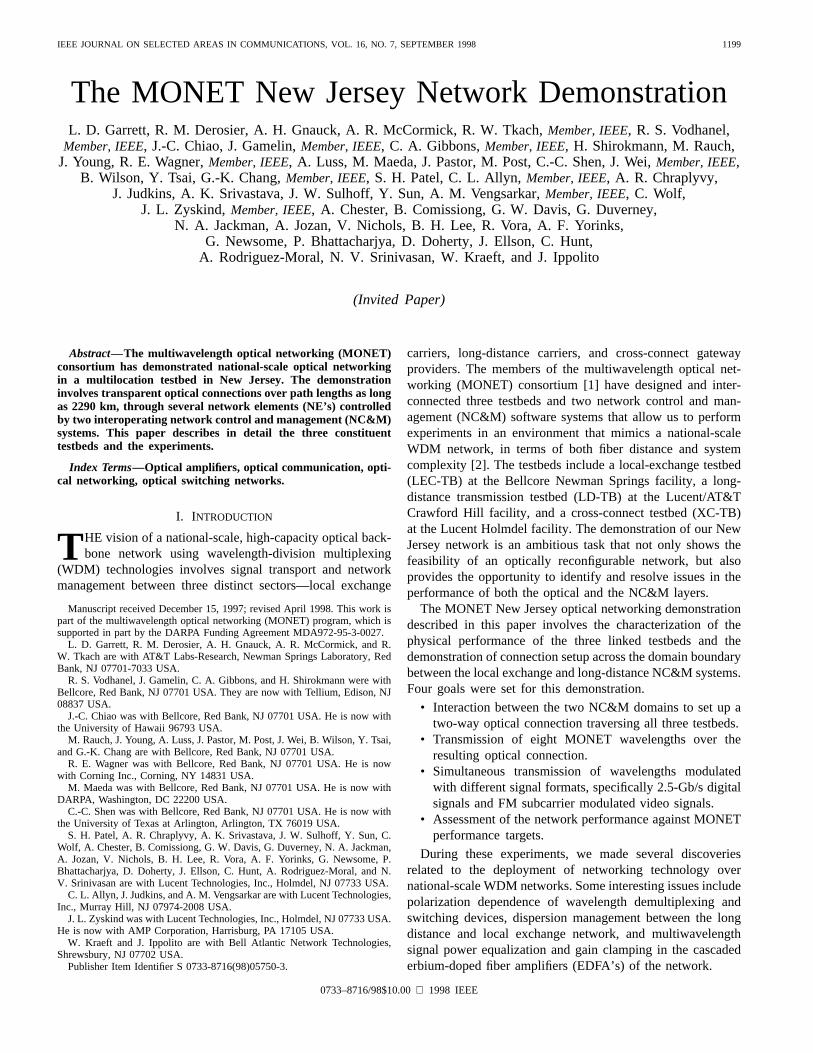
Included in the physical layer of the New Jersey network isan asynchronous transfer mode (ATM) fiber network support-ing the data communications network (DCN) required by theMONET NC&M system. As shown in Fig. 4, the DCN linksall controlled elements (NC&M management workstations andNE controllers) within the New Jersey network and transmitsNC&M information both within and between the two NC&Mdomains.
III. AT&T/L UCENT LONG DISTANCE TESTBED
The LD-TB plays a crucial role in the MONET pro-gram demonstration of the feasibility and benefits of trulynational-scale optical networking. The long-distance propa-gation studies are necessary to provide the understandingrequired to generate specifications for commercial large-scale
optical networks. The key transmission issues are chromaticdispersion and optical nonlinearity in the optical fiber, gainflatness in the optical amplifiers, and maintenance of sufficientsignal-to-noise ratio (SNR) throughout the network.
Each of the two 1040-km long-distance fiber spans of theLD-TB consist of seven 80-km lengths of negative nonzerodispersion shifted fiber [(N-NZDSF), 2.3ps/nm-km] and six80-km lengths of positive NZDSF [(P-NZDSF),2.3 ps/nm-km] fiber connected between 14 MONET EDFA’s [3] op-erating at 5 dBm/ch. Thus, each fiber span has low totaldispersion while maintaining finite local dispersion to reducenonlinear effects. The individual 80-km fiber lengths of thetwo long-distance spans were carefully chosen to result inclosely matched total dispersion values of83 ps/nm and 47ps/nm, measured at 1555 nm. When the LD-TB is connectedto the New Jersey network, additional negative dispersion isrequired to compensate for the dispersion of the 200 km ofconventional single-mode fiber (CF,17 ps/nm-km) of theLEC-TB and the testbed interconnection fiber. To accomplishthis, we connected three dispersion-compensating fiber (DCF)
1202 IEEE JOURNAL ON SELECTED AREAS IN COMMUNICATIONS, VOL. 16, NO. 7, SEPTEMBER 1998
Fig. 4. New Jersey Testbed network highlighting data communication network (DCN) links.
spans to the long-distance transmission spans before returningsignals to the XC-TB. DCF has high dispersion (80 to 90ps/nm-km), high loss (more than 0.5 dB/km), and a highnonlinearity coefficient. Therefore, the compensating spansconsist of an EDFA, an in-line optical attenuator to reducethe input power to the DCF, and an 8-km DCF span thatcompensates for the dispersion of 40 km of SMF. The DCFspans are not considered to contribute to the length of theLD-TB.
The long distance testbed currently contains six one-way network add/drop sites (WADM-NC) that are notunder NC&M control. Within each WADM-NC, the eightwavelengths are demultiplexed, equalized with in-line opticalattenuators, and remultiplexed. Both multilayer thin-film andwaveguide phased-array (WGR) multiplexing devices wereused. It should be noted, however, that transmission throughall 2080 km has been achieved with acceptable performanceon all wavelengths without any power leveling. The totalWADM-NC insertion loss is 10 dB with thin-film mux/demuxdevices and 20 dB with WGR mux/demux devices. EachWADM-NC is always followed by a MONET EDFA to boostthe output power back to standard levels.
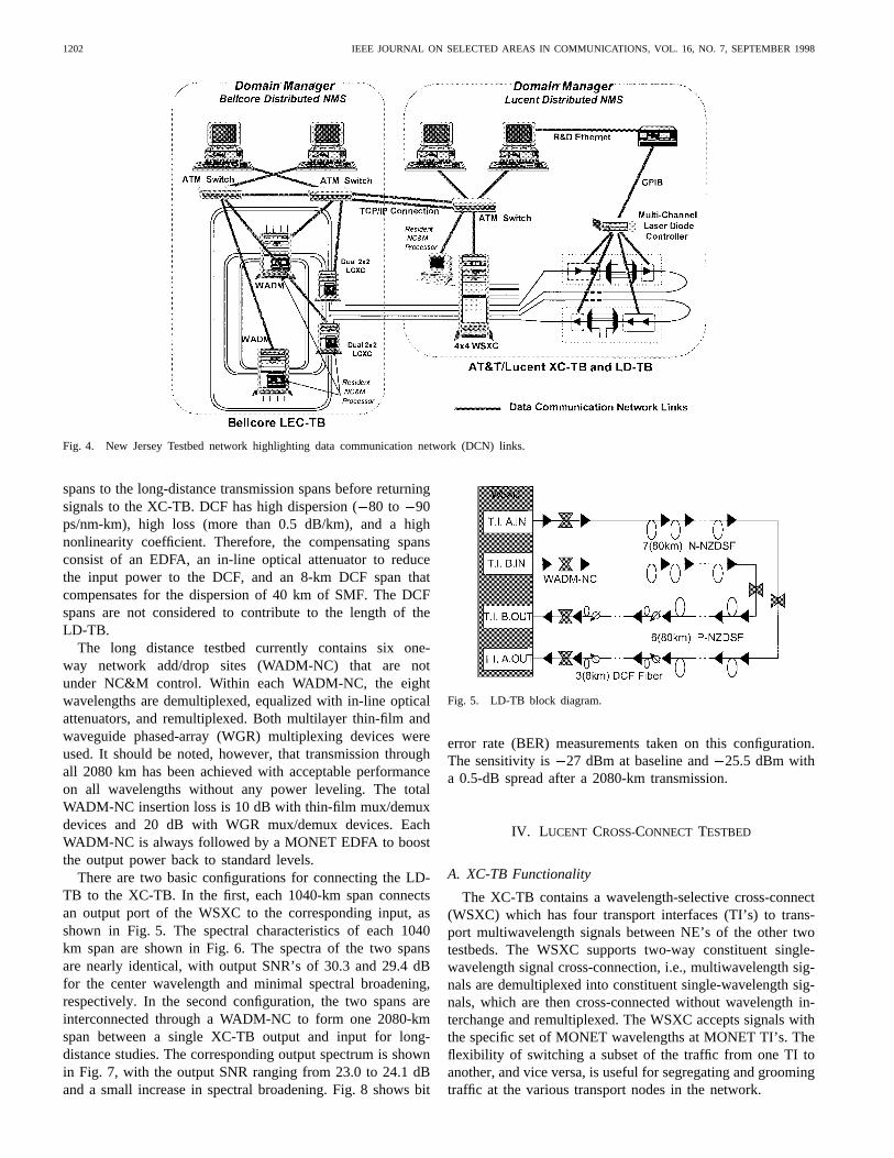
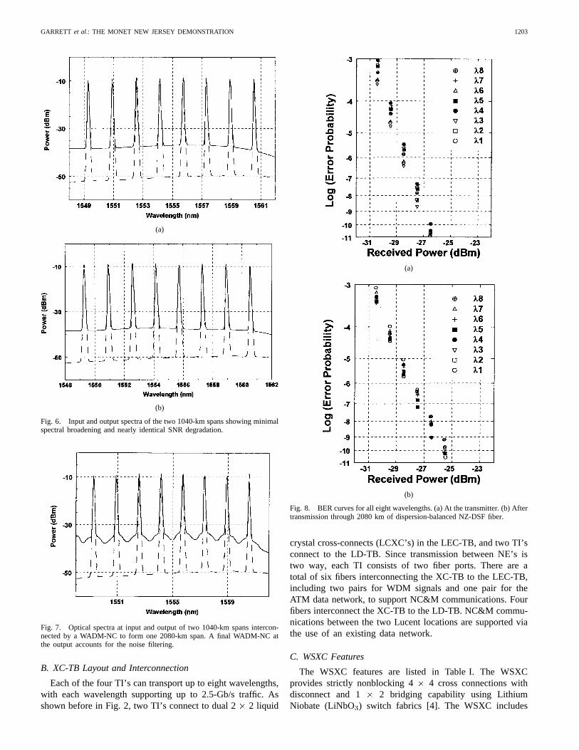
There are two basic configurations for connecting the LD-TB to the XC-TB. In the first, each 1040-km span connectsan output port of the WSXC to the corresponding input, asshown in Fig. 5. The spectral characteristics of each 1040km span are shown in Fig. 6. The spectra of the two spansare nearly identical, with output SNR’s of 30.3 and 29.4 dBfor the center wavelength and minimal spectral broadening,respectively. In the second configuration, the two spans areinterconnected through a WADM-NC to form one 2080-kmspan between a single XC-TB output and input for long-distance studies. The corresponding output spectrum is shownin Fig. 7, with the output SNR ranging from 23.0 to 24.1 dBand a small increase in spectral broadening. Fig. 8 shows bit
Fig. 5. LD-TB block diagram.
error rate (BER) measurements taken on this configuration.The sensitivity is 27 dBm at baseline and25.5 dBm witha 0.5-dB spread after a 2080-km transmission.
IV. L UCENT CROSS-CONNECT TESTBED
A. XC-TB Functionality
The XC-TB contains a wavelength-selective cross-connect(WSXC) which has four transport interfaces (TI’s) to trans-port multiwavelength signals between NE’s of the other twotestbeds. The WSXC supports two-way constituent single-wavelength signal cross-connection, i.e., multiwavelength sig-nals are demultiplexed into constituent single-wavelength sig-nals, which are then cross-connected without wavelength in-terchange and remultiplexed. The WSXC accepts signals withthe specific set of MONET wavelengths at MONET TI’s. Theflexibility of switching a subset of the traffic from one TI toanother, and vice versa, is useful for segregating and groomingtraffic at the various transport nodes in the network.
GARRETT et al.: THE MONET NEW JERSEY DEMONSTRATION 1203
(a)
(b)
Fig. 6. Input and output spectra of the two 1040-km spans showing minimalspectral broadening and nearly identical SNR degradation.
Fig. 7. Optical spectra at input and output of two 1040-km spans intercon-nected by a WADM-NC to form one 2080-km span. A final WADM-NC atthe output accounts for the noise filtering.
B. XC-TB Layout and Interconnection
Each of the four TI’s can transport up to eight wavelengths,with each wavelength supporting up to 2.5-Gb/s traffic. Asshown before in Fig. 2, two TI’s connect to dual 22 liquid
(a)
(b)
Fig. 8. BER curves for all eight wavelengths. (a) At the transmitter. (b) Aftertransmission through 2080 km of dispersion-balanced NZ-DSF fiber.
crystal cross-connects (LCXC’s) in the LEC-TB, and two TI’sconnect to the LD-TB. Since transmission between NE’s istwo way, each TI consists of two fiber ports. There are atotal of six fibers interconnecting the XC-TB to the LEC-TB,including two pairs for WDM signals and one pair for theATM data network, to support NC&M communications. Fourfibers interconnect the XC-TB to the LD-TB. NC&M commu-nications between the two Lucent locations are supported viathe use of an existing data network.
C. WSXC Features
The WSXC features are listed in Table I. The WSXCprovides strictly nonblocking 4 4 cross connections withdisconnect and 1 2 bridging capability using LithiumNiobate (LiNbO ) switch fabrics [4]. The WSXC includes
1204 IEEE JOURNAL ON SELECTED AREAS IN COMMUNICATIONS, VOL. 16, NO. 7, SEPTEMBER 1998
TABLE IMONET WAVELENGTH SELECTIVE CROSS-CONNECT FEATURES
TABLE IIPERFORMANCE OF WSXC AGAINST TARGET REQUIREMENTS
optical backplane interconnections, optical signal performancemonitoring on all TI’s, and a system controller with an NC&Minterface. The NC&M/NE interface is transmission controlprotocol/Internet protocol (TCP/IP) over ATM on an OC-3cphysical layer. The WSXC responds to NC&M commandsand messages. In addition, a local craft interface will besupported with approximately 50 operations, administrations,maintenance, & provisioning (OAM&P) messages.
The WSXC is designed to meet the target specifications,including signal power requirements for TI interfaces andend-to-end transmission impairments, in terms of crosstalk,eye margin, and SNR. The WSXC is transparent to signalattributes such as signal format, bit rate, and modulationformat over a specific set of wavelength at the MONETTI’s. Table II demonstrates the WSXC performance againstthe target requirements.
The WSXC provides two levels of performance monitoring(PM) to detect failures and degradation of optical signals andcomponents. The first level (PM for a single wavelength signaland PM( ) for multiwavelength signals) responds quickly todetect the presence or absence of single wavelength or multi-wavelength signals. The second level, enhanced performancemonitoring (EPM) (EPM ) for multiwavelength signals, is
more accurate and can measure the wavelength, power level,and SNR of any signal to be cross-connected. The WSXC can,with the aid of its performance monitoring capability, isolatea fault due to equipment failure within the NE. Loopbackfeatures facilitate testing and fault isolation between nodes,including split-loopback, bidirectional loopback, and manualloopback. The WSXC supports visual alarm indications andprovides alarm indication messages for failures of individualcircuit packs. In addition, it contains a set of three systemLED’s to indicate overall system status with alarm levels ofminor, major, or critical.
D. WSXC Architecture
As shown in Fig. 9, the WSXC is implemented as a singlebay cabinet. It consists of a system controller complex, anoptical transmission module, a multiwavelength meter, anda power supply and fuse panel. The optical transmissionmodule includes input transfer interface (TI_IN) interfaces,input transfer out (TI_OUT) interfaces, the SWITCH, andmonitoring. The multiwavelength meter is used for opticalsignal performance monitoring of signal levels, SNR, andwavelength misalignment on an individual wavelength ba-

GARRETT et al.: THE MONET NEW JERSEY DEMONSTRATION 1205
Fig. 9. WSXC bay.
Fig. 10. WSXC architecture block diagram.
sis. As shown in Fig. 10, the transmission architecture ofthe WSXC, in total, utilizes four input optical amplifiers,four demultiplexers, an eight-layer 4 4 switch fabric, fourremultiplexers, and four output optical amplifiers.
Each TI_IN optical input signal is monitored for the powerlevel, wavelength registration, and SNR of each wavelength,and amplified and then demultiplexed into single-wavelengthsignals ( – ). Each single wavelength signal is then mon-itored for power level and connected to the appropriate layerof the switch fabric. The switch fabric consists of eightseparate wavelength layers with a 44 LiNbO switch foreach layer. Any of the four inputs on each wavelength layercan be connected to any of the four outputs of the samelayer. Loss compensation and the switch configuration are
controlled by the system controller. At the switch output,the single-wavelength signals (one from each of the eightlayers of the switch fabric) are multiplexed together andamplified to produce the four TI_OUT signals. Each opticalTI_OUT output signal is monitored for total power and forconstituent wavelength signal power, wavelength registration,and SNR.
V. BELLCORE LOCALEXCHANGE TESTBED (LEC-TB)
A. LEC-TB Configuration
The LEC-TB plays three important roles: 1) assessing localexchange network architectures; 2) providing NC&M managedclient signals for the network demonstration; and 3) evaluatinga variety of NE’s with essential functions for WDM opticalnetworking. Two levels of network layers were designed andintegrated in the LEC-TB: a WDM transport layer and anoverlay ATM data communication layer.
The WDM transport layer consists of a WDM survivablering with four NE’s, including two wavelength add/drop multi-plexers (WADM’s), two dual 2 2 LCXC’s, and five networkcomponents, including one wavelength selective cross-connect(WSXC-NC) and four WADM-NC’s. The control and manage-ment of the four NE’s of the LEC-TB formed the basis of areconfigurable New Jersey network for adding and droppingsingle wavelength client signals to demonstrate a national-scale, two-domain, three-testbed, LEC-LD-LEC experiment.The LEC-TB configuration is depicted in Fig. 2, where thefive network components were deployed to ensure adequate8- signal conditioning. In particular, one of the networkcomponents was used to inject 8-filling signals into thefiber rings. Thus, the input power levels to all EDFA’semployed in the NE’s and components were maintained toattain an optimized flat gain curve to meet the MONETtarget specifications. The detailed design and operation of theLCXC’s will be described in Section V-C. We summarize theperformance and requirements of the WADM’s in Section V-D.
1) DCN for the LEC-TB:The four NE’s, WADM1,WADM2, LCXC1, and LCXC2, in the LEC-TB wereconnected to NC&M stations through the ATM switchedDCN. The architecture of this ATM overlay layer is depictedin Fig. 11. NE controllers located in the four NE’s arecommunicating with NC&M agents residing in SPARC-5stations, through ATM computer interface modules operatingat the OC-3 rate. The NC&M agents communicate with theNC&M stations, SPARC-20, connected to ATM switchesthrough separate ATM-computer modules. The intent is tobuild a robust data communication network. Transmitters andreceivers for the DCN operate at 1310 nm.
B. LCXC
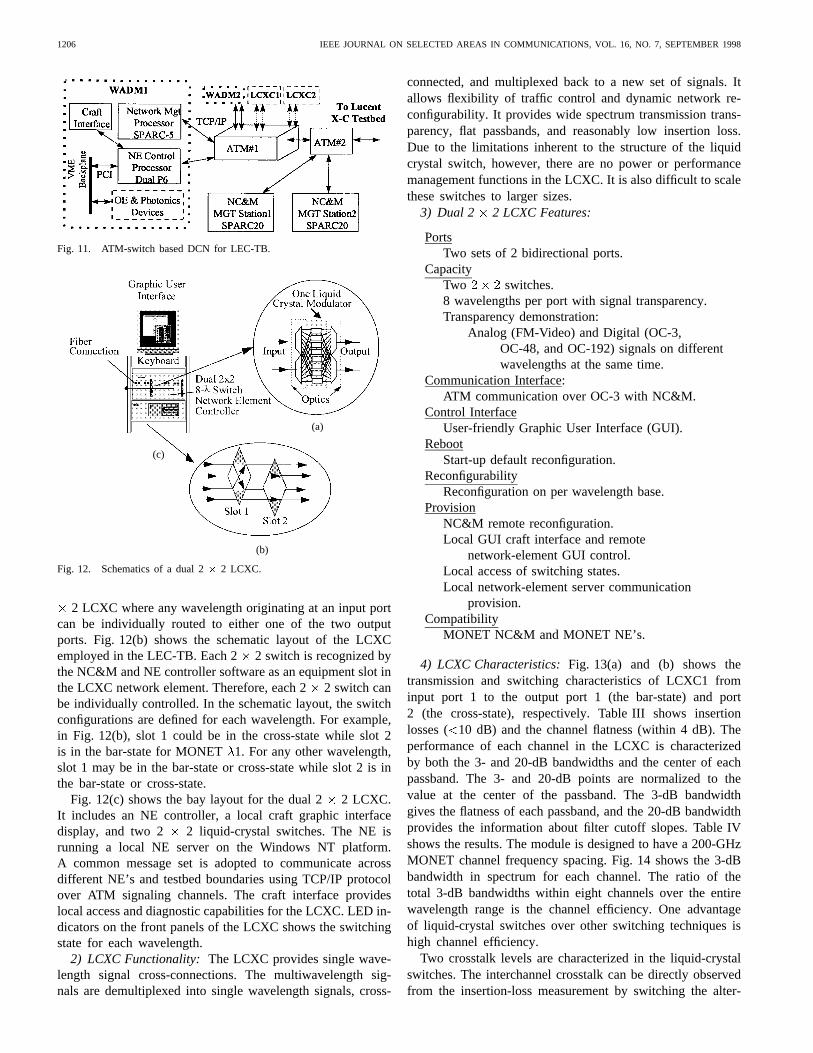
1) LCXC Overview:Two dual 2 2 LCXC’s are used toroute individual wavelengths between two two-fiber rings inopposite transmission directions. Both switches are designedfor the MONET wavelength spacing of 200 GHz. Fig. 12(a)shows the schematic configuration of the eight-wavelength 2
1206 IEEE JOURNAL ON SELECTED AREAS IN COMMUNICATIONS, VOL. 16, NO. 7, SEPTEMBER 1998
Fig. 11. ATM-switch based DCN for LEC-TB.
(a)
(c)
(b)
Fig. 12. Schematics of a dual 2� 2 LCXC.
2 LCXC where any wavelength originating at an input portcan be individually routed to either one of the two outputports. Fig. 12(b) shows the schematic layout of the LCXCemployed in the LEC-TB. Each 2 2 switch is recognized bythe NC&M and NE controller software as an equipment slot inthe LCXC network element. Therefore, each 22 switch canbe individually controlled. In the schematic layout, the switchconfigurations are defined for each wavelength. For example,in Fig. 12(b), slot 1 could be in the cross-state while slot 2is in the bar-state for MONET 1. For any other wavelength,slot 1 may be in the bar-state or cross-state while slot 2 is inthe bar-state or cross-state.
Fig. 12(c) shows the bay layout for the dual 22 LCXC.It includes an NE controller, a local craft graphic interfacedisplay, and two 2 2 liquid-crystal switches. The NE isrunning a local NE server on the Windows NT platform.A common message set is adopted to communicate acrossdifferent NE’s and testbed boundaries using TCP/IP protocolover ATM signaling channels. The craft interface provideslocal access and diagnostic capabilities for the LCXC. LED in-dicators on the front panels of the LCXC shows the switchingstate for each wavelength.
2) LCXC Functionality: The LCXC provides single wave-length signal cross-connections. The multiwavelength sig-nals are demultiplexed into single wavelength signals, cross-
connected, and multiplexed back to a new set of signals. Itallows flexibility of traffic control and dynamic network re-configurability. It provides wide spectrum transmission trans-parency, flat passbands, and reasonably low insertion loss.Due to the limitations inherent to the structure of the liquidcrystal switch, however, there are no power or performancemanagement functions in the LCXC. It is also difficult to scalethese switches to larger sizes.
3) Dual 2 2 LCXC Features:
PortsTwo sets of 2 bidirectional ports.
CapacityTwo switches.8 wavelengths per port with signal transparency.Transparency demonstration:
Analog (FM-Video) and Digital (OC-3,OC-48, and OC-192) signals on differentwavelengths at the same time.
Communication Interface:ATM communication over OC-3 with NC&M.
Control InterfaceUser-friendly Graphic User Interface (GUI).
RebootStart-up default reconfiguration.
ReconfigurabilityReconfiguration on per wavelength base.
ProvisionNC&M remote reconfiguration.Local GUI craft interface and remote
network-element GUI control.Local access of switching states.Local network-element server communication
provision.Compatibility
MONET NC&M and MONET NE’s.
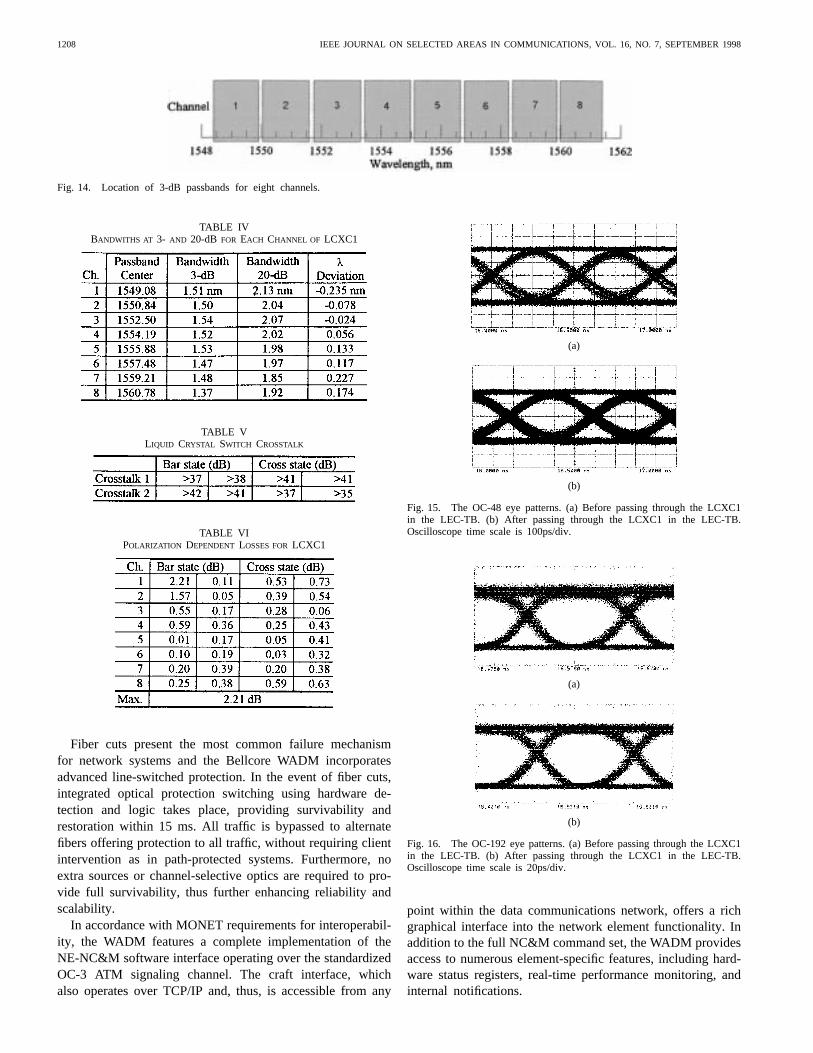
4) LCXC Characteristics:Fig. 13(a) and (b) shows thetransmission and switching characteristics of LCXC1 frominput port 1 to the output port 1 (the bar-state) and port2 (the cross-state), respectively. Table III shows insertionlosses ( 10 dB) and the channel flatness (within 4 dB). Theperformance of each channel in the LCXC is characterizedby both the 3- and 20-dB bandwidths and the center of eachpassband. The 3- and 20-dB points are normalized to thevalue at the center of the passband. The 3-dB bandwidthgives the flatness of each passband, and the 20-dB bandwidthprovides the information about filter cutoff slopes. Table IVshows the results. The module is designed to have a 200-GHzMONET channel frequency spacing. Fig. 14 shows the 3-dBbandwidth in spectrum for each channel. The ratio of thetotal 3-dB bandwidths within eight channels over the entirewavelength range is the channel efficiency. One advantageof liquid-crystal switches over other switching techniques ishigh channel efficiency.
Two crosstalk levels are characterized in the liquid-crystalswitches. The interchannel crosstalk can be directly observedfrom the insertion-loss measurement by switching the alter-

GARRETT et al.: THE MONET NEW JERSEY DEMONSTRATION 1207
(a)
(b)
Fig. 13. Transmittance of an eight-wavelength 2� 2 LCXC1. (a) In the barstate. (b) In the cross state.
TABLE IIIINSERTION LOSSES ANDCHANNEL FLATNESS FOR LCXC1
nate channels on or off. The interchannel crosstalk can bereduced to better than 37 dB. The switching crosstalk is thepower leakage between the outputs at the same wavelength.The alternate channels are set to the cross-state to measurethe switching crosstalk in order to avoid crosstalk from theadjacent channels. For one input, each channel needs tobe individually measured with both outputs and differentswitching states. Table V shows the switching crosstalk.
The polarization dependent loss (PDL) is defined as themaximum insertion-loss change as different polarization statespass through the devices. The PDL characterization includedboth bar-states and cross-states. Table VI shows the measured
PDL data obtained from LCXC1. The reflectivity was alsomeasured for each port, with return losses better than 34 dBfor all states of all input and output ports.
As a transparency test, OC-48 (2.488 Gb/s) and OC-192(9.952 Gb/s) signals were applied through the LCXC on twowavelengths (3 and 5, respectively) while FM-video signalwas applied on one wavelength (4) at the same time. Theprimary degradation from passing through the LCXC willbe crosstalk from the other inputs. Figs. 15 and 16 showthe eye-diagrams both before and after passing through theswitch for the OC-48 and OC-192 signals, respectively, withno significant change in eye shape. Fig. 17 shows the BERmeasurements after passing the LCXC for the OC-48 andOC-192 signals, as compared with the baseline measurementswith a pseudorandom data 2 and 2 , respectively.The sensitivity of 33.6 dBm at the OC-192 rate was attainedusing an optically preamplified receiver in conjunction with atunable narrow band filter.
C. WADM
1) WADM Functionality: The WADM supports opticaladd/drop capability from a multiwavelength transport facility.Individual demultiplexed channels can be arbitrarily addedto or dropped from the transport facility or transparentlypassed through. This functionality forms the basis for linearchain architectures in both point-to-point configurations andself-healing ring networks.
2) WADM Features:The Bellcore WADM for the LEC-TBsupports both chain and ring network architectures. Four-fiberbidirectional line-switched operation in analogy with currentSONET ring systems is provided through installation of anoptional protection switch circuit pack. The WADM allows fulloptical add/drop (8-, 100% of line capacity) compatible withboth compliant and noncompliant (wavelength-regenerated)interfaces. An all-optical internal design provides full opti-cal transparency for all wavelength channels. The BellcoreWADM supports several unique features: 1) an all-optical am-plifier fixed-gain control; 2) hardware-based dynamic channelequalization; and 3) multimode line protection switching.
Channel-dependent behavior of optical amplifiers can dis-turb nonparticipating wavelength signals in the event of dy-namic reconfiguration, network upgrade, and fiber or nodefailure situations [5]. The WADM incorporates all-opticalfeedback stabilized amplifiers [6] to maintain constant gain inenvironments where channel powers and numbers fluctuate.The all-optical feedback control regulates the gain withinmicroseconds, sufficient to stabilize transients over ten or morenetwork element stages.
In addition to overall multiwavelength changes, variationsbetween channels due to rerouting and client signal irregu-larities necessitate the introduction of dynamic per-channelsignal conditioning. The WADM uniquely provides hardware-based equalization using high-speed mechanical attenuators.Stabilization of 1-dB transients within 10 ms can be achievedfor each channel. Slower software-based solutions can limitthe network reconfiguration speed and allow performancedegrading transients to affect other wavelength channels.
1208 IEEE JOURNAL ON SELECTED AREAS IN COMMUNICATIONS, VOL. 16, NO. 7, SEPTEMBER 1998
Fig. 14. Location of 3-dB passbands for eight channels.
TABLE IVBANDWITHS AT 3- AND 20-dB FOR EACH CHANNEL OF LCXC1
TABLE VLIQUID CRYSTAL SWITCH CROSSTALK
TABLE VIPOLARIZATION DEPENDENT LOSSES FORLCXC1
Fiber cuts present the most common failure mechanismfor network systems and the Bellcore WADM incorporatesadvanced line-switched protection. In the event of fiber cuts,integrated optical protection switching using hardware de-tection and logic takes place, providing survivability andrestoration within 15 ms. All traffic is bypassed to alternatefibers offering protection to all traffic, without requiring clientintervention as in path-protected systems. Furthermore, noextra sources or channel-selective optics are required to pro-vide full survivability, thus further enhancing reliability andscalability.
In accordance with MONET requirements for interoperabil-ity, the WADM features a complete implementation of theNE-NC&M software interface operating over the standardizedOC-3 ATM signaling channel. The craft interface, whichalso operates over TCP/IP and, thus, is accessible from any
(a)
(b)
Fig. 15. The OC-48 eye patterns. (a) Before passing through the LCXC1in the LEC-TB. (b) After passing through the LCXC1 in the LEC-TB.Oscilloscope time scale is 100ps/div.
(a)
(b)
Fig. 16. The OC-192 eye patterns. (a) Before passing through the LCXC1in the LEC-TB. (b) After passing through the LCXC1 in the LEC-TB.Oscilloscope time scale is 20ps/div.
point within the data communications network, offers a richgraphical interface into the network element functionality. Inaddition to the full NC&M command set, the WADM providesaccess to numerous element-specific features, including hard-ware status registers, real-time performance monitoring, andinternal notifications.

GARRETT et al.: THE MONET NEW JERSEY DEMONSTRATION 1209
(a) (b)
Fig. 17. BER performance of LCXC1 in the testbed. (a) At 2.488 Gb/s (OC-48). (b) At 9.952 Gb/s (OC-192).
3) WADM Description and Architecture :The BellcoreWADM resides in a single-bay rack, and it consists ofa multiwavelength performance monitor module, systemcontroller, and two transmission shelves for EAST and WESTdirections, respectively. The transmission equipment includessix optical circuit packs: (optional) automatic protection switch(APS), TI_IN, TI_OUT, switch fabric (SF), channel powerequalization (CPE), and compliant client interfaces (CCI).Each shelf represents a single transmission path and containsone of each circuit pack, as well as an embedded electroniccontroller and monitoring modules.
The TI’s provide multiplexing and demultiplexing of theconstituent channels and appropriate amplification to over-come fiber and component losses. Reliable high-performanceopto-mechanical 2 2 switches then switch the individualchannels to provide local access or pass through. All add anddrop operations are performed through the client interfacescircuit pack. The channel power equalizer conditions the wave-length channels independently, using high-speed hardwarefeedback-controlled variable optical attenuators.
Performance monitoring takes place both at the networkelement edges (to isolate external failures) as well as at internallocations. All input and output ports are sequentially polledand monitored for channel power, wavelength registration, andSNR. Within the client interfaces the individual connectionsare optical combined to resemble TI’s. A wavelength meter,in tandem with a 1 12 optical switch, is used to providethe detailed channel measurements. Internally, fast individualchannel power measurements using optical taps and fast pho-todetectors are made at add, drop, and equalization points forrapid detection of failures.
As indicated in Fig. 11, overall element control is providedby a dual-processor system computer inside the WADM. Thecontroller system includes an interface to the embedded circuitpacks and wavelength meter, as well as the OC-3 ATM opticalinterface to the NC&M system. Optionally, a video display isprovided for convenient access for network element provi-sioning. The entire network element is powered by 120 V ACthrough a rack line conditioner.
VI. NEW JERSEY FIBER PLANT
Six single-mode fibers, approximately 27.3 km in length,provided by Bell Atlantic, connect the LEC-TB at the BellcoreNewman Springs location and the XC-TB at the LucentTechnologies Holmdel location. The Lucent XC-TB and theLucent/AT&T LD-TB, located at Lucent Technologies Craw-ford Hill Laboratory, are then connected by four single-modefibers, approximately 5 km in length, belonging to Lucent.
A. Fiber Usage
Of the six fibers provided between Bellcore on NewmanSprings Road, and Lucent Technologies in Holmdel, four fibersconnect MONET NE’s and two fibers connect the MONETNC&M systems via ATM switches placed at each location.The four fibers with the best transmission loss characteristicswere chosen to connect the high-speed MONET NE’s, andthe two remaining fibers connect the lower speed NC&M datacommunications network. All four fibers between the LucentTechnologies locations at Holmdel and Crawford Hill wereused to connect MONET NE’s. NC&M functions betweenthese two locations are accomplished over an existing Lucentdata network.
B. Fiber Outside Plant Testing
The six Bell Atlantic fibers were examined using a TektronixFiberMaster test set, with results listed in Table VII. The re-sults indicate total fiber transmission losses between Bellcore,Newman Springs Road, and Lucent Technologies in Holmdelwell within the specified limits of less than 18 dB in the 1550-nm window. In most cases, optical return loss measured betterthan the target 40 dB, but several fiber cross-connect pointsdid not meet this requirement. During early July of 1996, BellAtlantic technicians replaced an entire fiber patch panel at theLucent Technologies Holmdel location and cleaned or replacedfiber cross-connects in the Bell Atlantic central offices. Thereare still some points in the Bell Atlantic MONET New JerseyFiber Network that do not meet the 40-dB optical reflectancecriteria. It has been confirmed, however, that the current read-ings are acceptable for optical transmission rates of 2.5 Gb/s.
1210 IEEE JOURNAL ON SELECTED AREAS IN COMMUNICATIONS, VOL. 16, NO. 7, SEPTEMBER 1998
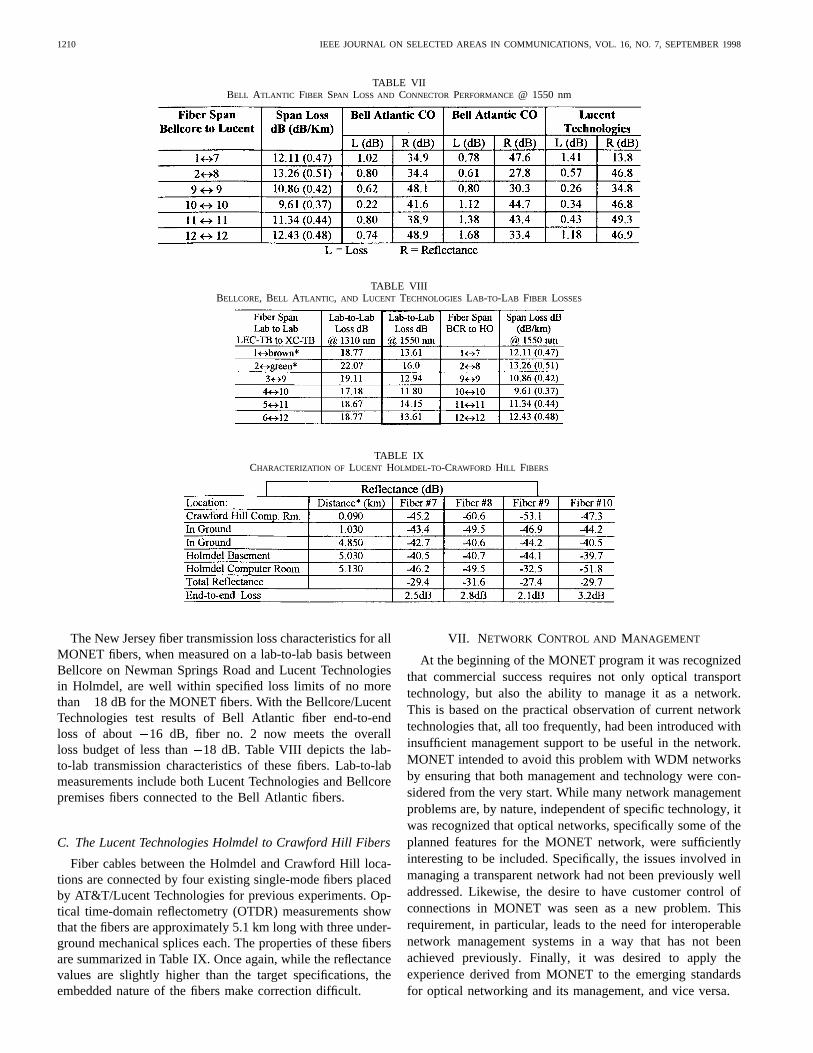
TABLE VIIBELL ATLANTIC FIBER SPAN LOSS AND CONNECTOR PERFORMANCE @ 1550 nm
TABLE VIIIBELLCORE, BELL ATLANTIC, AND LUCENT TECHNOLOGIES LAB-TO-LAB FIBER LOSSES
TABLE IXCHARACTERIZATION OF LUCENT HOLMDEL-TO-CRAWFORD HILL FIBERS
The New Jersey fiber transmission loss characteristics for allMONET fibers, when measured on a lab-to-lab basis betweenBellcore on Newman Springs Road and Lucent Technologiesin Holmdel, are well within specified loss limits of no morethan 18 dB for the MONET fibers. With the Bellcore/LucentTechnologies test results of Bell Atlantic fiber end-to-endloss of about 16 dB, fiber no. 2 now meets the overallloss budget of less than18 dB. Table VIII depicts the lab-to-lab transmission characteristics of these fibers. Lab-to-labmeasurements include both Lucent Technologies and Bellcorepremises fibers connected to the Bell Atlantic fibers.
C. The Lucent Technologies Holmdel to Crawford Hill Fibers
Fiber cables between the Holmdel and Crawford Hill loca-tions are connected by four existing single-mode fibers placedby AT&T/Lucent Technologies for previous experiments. Op-tical time-domain reflectometry (OTDR) measurements showthat the fibers are approximately 5.1 km long with three under-ground mechanical splices each. The properties of these fibersare summarized in Table IX. Once again, while the reflectancevalues are slightly higher than the target specifications, theembedded nature of the fibers make correction difficult.
VII. N ETWORK CONTROL AND MANAGEMENT
At the beginning of the MONET program it was recognizedthat commercial success requires not only optical transporttechnology, but also the ability to manage it as a network.This is based on the practical observation of current networktechnologies that, all too frequently, had been introduced withinsufficient management support to be useful in the network.MONET intended to avoid this problem with WDM networksby ensuring that both management and technology were con-sidered from the very start. While many network managementproblems are, by nature, independent of specific technology, itwas recognized that optical networks, specifically some of theplanned features for the MONET network, were sufficientlyinteresting to be included. Specifically, the issues involved inmanaging a transparent network had not been previously welladdressed. Likewise, the desire to have customer control ofconnections in MONET was seen as a new problem. Thisrequirement, in particular, leads to the need for interoperablenetwork management systems in a way that has not beenachieved previously. Finally, it was desired to apply theexperience derived from MONET to the emerging standardsfor optical networking and its management, and vice versa.
GARRETT et al.: THE MONET NEW JERSEY DEMONSTRATION 1211
In keeping with current trends in network managementstandards and computing practices, the management systemis designed around distributed computing concepts and usesthe ITU-T Recommendation SG15 specification techniques forinterface design. To ensure that interoperability issues werereally addressed, it was decided to use two different systeminfrastructures, as would be expected in a very large network.We did not want to achieve interoperability that dependedstrongly on the choice of computing platform.
A. NC&M Architecture and Design for theLucent Domain (XC-TB and LD-TB)
1) System Architecture:The Lucent Technologies NC&Msystem for the MONET New Jersey Testbed is a scaleable andfully distributed management system implementation whichutilizes pertinent existing and evolving standards applicableto WDM optical networking. Fundamental to the architectureis use of a new enabling technology that supports distributedgraphs. Underlying distribution support and related distributiontransparencies are provided by the CAST+HOTframe plat-form, where HOTframe is a leading edge CORBA-compliant(common object request broker architecture) distributed in-frastructure, and CAST consists of the interface definitionlanguage (IDL) and module interconnection language (MIL)for easy specification of distributed object-based systems.HOTframe also provides support for persistence and dynamicreconfigurability of distributed systems necessary for achiev-ing fault tolerance. This distributed NC&M system may beused to support multitiered TMN management architectures, aswell as fully distributed management architectures which havenot been traditionally used by telecommunications networks,but which are arising in evolving data networking/internetarenas.
The following are its features.
1) It implements NC&M-NE Interface to XC-TB WSXC(including inventory, configuration, connection setup,disconnect).
2) It implements the NC&M-NC&M nterface to the Bell-core domain (for connection setup/tear-down).
3) It implements optical amplifier control and monitoring,using distributed virtual instruments.
The distributed NC&M system is being used within the NewJersey network to support the management needs/capabilitiesof NE’s and components within the XC-TB and LD-TB (i.e.,functionalities as provided by the WSXC in the XC-TB andthe optical amplifiers in the LD-TB). In addition to Lucentdomain management, it is being used to support interdomainconnection setup with the LEC-TB, which is performed viainterface to the Bellcore NC&M system. The graphical userinterface (GUI) of the system provides dynamic visualizationfor views of interest to the user and implements the distributedvirtual instrument approach to provide for functionality, havinga recognizably common look and feel across various GUIplatforms (including the WEB based). This is achieved viaa location independent (i.e., from any computing platform andhence distributed) and platform independent description of theuser interface (virtual instrument), in addition to a dynamic
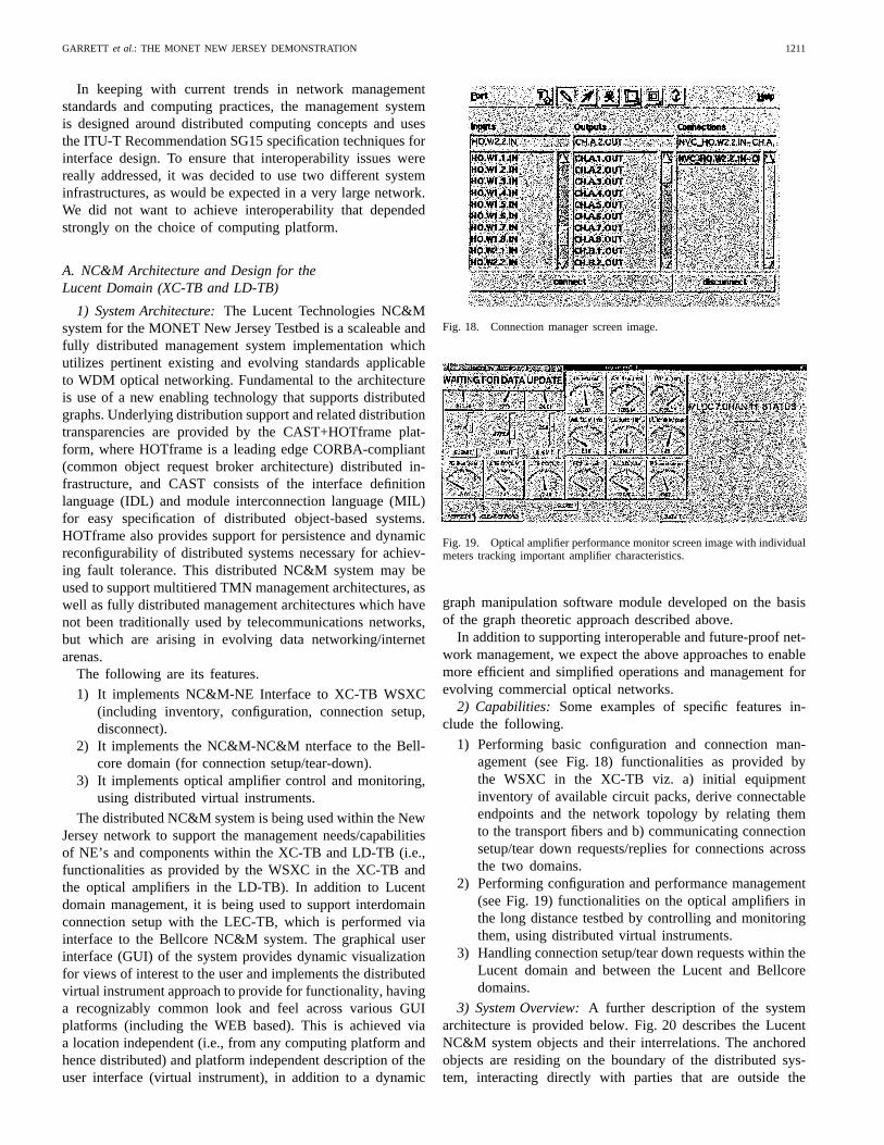
Fig. 18. Connection manager screen image.
Fig. 19. Optical amplifier performance monitor screen image with individualmeters tracking important amplifier characteristics.
graph manipulation software module developed on the basisof the graph theoretic approach described above.
In addition to supporting interoperable and future-proof net-work management, we expect the above approaches to enablemore efficient and simplified operations and management forevolving commercial optical networks.
2) Capabilities: Some examples of specific features in-clude the following.
1) Performing basic configuration and connection man-agement (see Fig. 18) functionalities as provided bythe WSXC in the XC-TB viz. a) initial equipmentinventory of available circuit packs, derive connectableendpoints and the network topology by relating themto the transport fibers and b) communicating connectionsetup/tear down requests/replies for connections acrossthe two domains.
2) Performing configuration and performance management(see Fig. 19) functionalities on the optical amplifiers inthe long distance testbed by controlling and monitoringthem, using distributed virtual instruments.
3) Handling connection setup/tear down requests within theLucent domain and between the Lucent and Bellcoredomains.
3) System Overview:A further description of the systemarchitecture is provided below. Fig. 20 describes the LucentNC&M system objects and their interrelations. The anchoredobjects are residing on the boundary of the distributed sys-tem, interacting directly with parties that are outside the

1212 IEEE JOURNAL ON SELECTED AREAS IN COMMUNICATIONS, VOL. 16, NO. 7, SEPTEMBER 1998
Fig. 20. Lucent NC&M system objects.
Lucent Technologies management domain viz. the WSXCor the Bellcore NC&M system. Hence, they are locatedon fixed workstations. The rest of the system objects canbe located on any of the workstations that are part of thesame distributed environment, as enforced by the distributedinfrastructure.
The NE anchored object interacts with the WSXC andthe interdomain anchored object interacts with the similarobject on Bellcore NC&M domain via the DCN. The opticalamplifiers (OA’s) of the LD-TB are controlled by the OAanchored object using a GPIB bus. The subnetwork object isconcerned with connections involving CTP’s on the Lucentsubnet while the New Jersey network object handles con-nections across both Lucent and Bellcore subnetworks. TheGUI objects provide end-users with the graphical interface tointeract with the Lucent subnetwork and can interact with anyobject inside (hence the connectivity with rest of the systemis not specified explicitly).
B. NC&M Architecture and Design for LEC-TB
1) System Architecture:The Bellcore MONET networkmanagement system (NMS) is a next-generation networkmanagement system prototype designed to provide networkmanagement support for emerging WDM optical networks.It is a fault-tolerant distributed NMS, with its design basedon the ITU-T multitier TMN-based network managementarchitecture and CORBA-based distributed object computingplatform, as shown in Fig. 21. The WDM NMS supports basicconfiguration, connection, performance, and fault managementcapabilities for wavelength add–drop multiplexers andwavelength cross-connects. It also provides a user friendlygraphical user interface for network/site maps, faceplate,alarms, and performance monitoring displays. It optimizesand simplifies the operations of future WDM optical networksand ensures their viability and deployability.
Fig. 21. NMS system architecture.
Fig. 22. Configuration manager.
2) Features:a) Configuration management:The configuration man-
ager provides capabilities to manage the network topology,such as network connectivity, network resources, and thenetwork map. It also provides the capabilities to manage indi-vidual NE’s, such as circuit packs inventory, NE wavelengthcross-connection, and support for remotely setting the portsand wavelengths to be in service or out of service. A userfriendly graphical user interface is provided to allow the userto access and control the network resources. As shown inFig. 22, the GUI interface provides pull down menus and easypoint-and-click invocation of management functions. Easy tounderstand icons are used to represent the network objects,such as network map, link, site, faceplate, and port.
b) Connection management:The connection managerprovides remote end-to-end connection setup and release forWDM paths and automatic route creation capability. Simplyspecify the end points of the connection to be created, andthe system will compute the shortest feasible path, issue thecommands to the NE’s along the path, and automaticallycreate the route. These paths can be created within the LEC-TB or can be constructed from the LEC-TB, to the Lucentdomain, and into the LD-TB. In the MONET LEC-TB at
GARRETT et al.: THE MONET NEW JERSEY DEMONSTRATION 1213
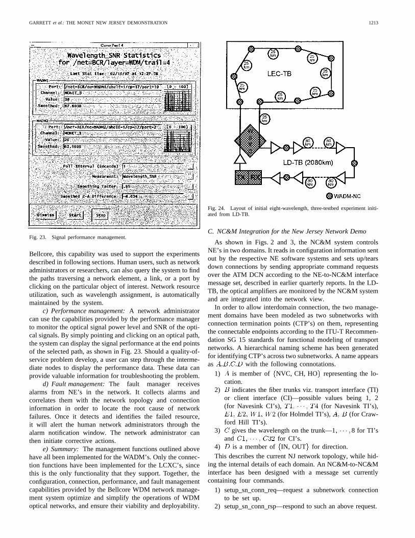
Fig. 23. Signal performance management.
Bellcore, this capability was used to support the experimentsdescribed in following sections. Human users, such as networkadministrators or researchers, can also query the system to findthe paths traversing a network element, a link, or a port byclicking on the particular object of interest. Network resourceutilization, such as wavelength assignment, is automaticallymaintained by the system.
c) Performance management:A network administratorcan use the capabilities provided by the performance managerto monitor the optical signal power level and SNR of the opti-cal signals. By simply pointing and clicking on an optical path,the system can display the signal performance at the end pointsof the selected path, as shown in Fig. 23. Should a quality-of-service problem develop, a user can step through the interme-diate nodes to display the performance data. These data canprovide valuable information for troubleshooting the problem.
d) Fault management:The fault manager receivesalarms from NE’s in the network. It collects alarms andcorrelates them with the network topology and connectioninformation in order to locate the root cause of networkfailures. Once it detects and identifies the failed resource,it will alert the human network administrators through thealarm notification window. The network administrator canthen initiate corrective actions.
e) Summary:The management functions outlined abovehave all been implemented for the WADM’s. Only the connec-tion functions have been implemented for the LCXC’s, sincethis is the only functionality that they support. Together, theconfiguration, connection, performance, and fault managementcapabilities provided by the Bellcore WDM network manage-ment system optimize and simplify the operations of WDMoptical networks, and ensure their viability and deployability.
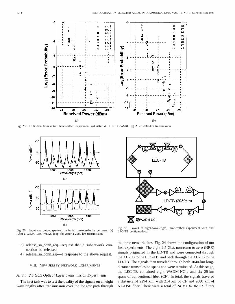
Fig. 24. Layout of initial eight-wavelength, three-testbed experiment initi-ated from LD-TB.
C. NC&M Integration for the New Jersey Network Demo
As shown in Figs. 2 and 3, the NC&M system controlsNE’s in two domains. It reads in configuration information sentout by the respective NE software systems and sets up/tearsdown connections by sending appropriate command requestsover the ATM DCN according to the NE-to-NC&M interfacemessage set, described in earlier quarterly reports. In the LD-TB, the optical amplifiers are monitored by the NC&M systemand are integrated into the network view.
In order to allow interdomain connection, the two manage-ment domains have been modeled as two subnetworks withconnection termination points (CTP’s) on them, representingthe connectable endpoints according to the ITU-T Recommen-dation SG 15 standards for functional modeling of transportnetworks. A hierarchical naming scheme has been generatedfor identifying CTP’s across two subnetworks. A name appearsas with the following connotations.
1) is member of NVC, CH, HO representing the lo-cation.
2) indicates the fiber trunks viz. transport interface (TI)or client interface (CI)—possible values being 1, 2(for Navesink CI’s), (for Navesink TI’s),
(for Holmdel TI’s), (for Craw-ford Hill TI’s).
3) gives the wavelength on the trunk—1 8 for TI’sand for CI’s.
4) is a member of IN, OUT for direction.
This describes the current NJ network topology, while hid-ing the internal details of each domain. An NC&M-to-NC&Minterface has been designed with a message set currentlycontaining four commands.
1) setup_sn_conn_req—request a subnetwork connectionto be set up.
2) setup_sn_conn_rsp—respond to such an above request.
1214 IEEE JOURNAL ON SELECTED AREAS IN COMMUNICATIONS, VOL. 16, NO. 7, SEPTEMBER 1998
(a) (b)
Fig. 25. BER data from initial three-testbed experiment. (a) After WSXC-LEC-WSXC (b) After 2080-km transmission.
(a)
(b)
Fig. 26. Input and output spectrum in initial three-testbed experiment. (a)After a WSXC-LEC-WSXC loop. (b) After a 2080-km transmission.
3) release_sn_conn_req—request that a subnetwork con-nection be released.
4) release_sn_conn_rsp—a response to the above request.
VIII. N EW JERSEY NETWORK EXPERIMENTS
A. 8 2.5 Gb/s Optical Layer Transmission Experiments
The first task was to test the quality of the signals on all eightwavelengths after transmission over the longest path through
Fig. 27. Layout of eight-wavelength, three-testbed experiment with finalLEC-TB configuration.
the three network sites. Fig. 24 shows the configuration of ourfirst experiments. The eight 2.5-Gb/s nonreturn to zero (NRZ)signals originated in the LD-TB and were connected throughthe XC-TB to the LEC-TB, and back through the XC-TB to theLD-TB. The signals then traveled through both 1040-km long-distance transmission spans and were terminated. At this stage,the LEC-TB contained eight WADM-NC’s and six 25-kmspans of conventional fiber (CF). In total, the signals traveleda distance of 2294 km, with 214 km of CF and 2080 km ofNZ-DSF fiber. There were a total of 24 MUX/DMUX filters
GARRETT et al.: THE MONET NEW JERSEY DEMONSTRATION 1215
(a) (b)
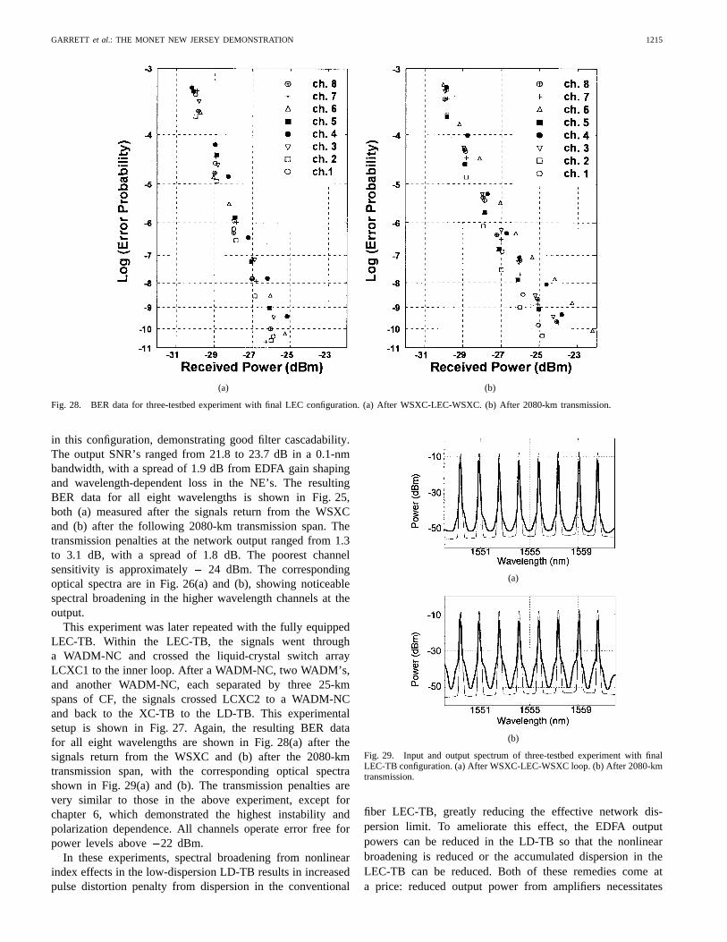
Fig. 28. BER data for three-testbed experiment with final LEC configuration. (a) After WSXC-LEC-WSXC. (b) After 2080-km transmission.
in this configuration, demonstrating good filter cascadability.The output SNR’s ranged from 21.8 to 23.7 dB in a 0.1-nmbandwidth, with a spread of 1.9 dB from EDFA gain shapingand wavelength-dependent loss in the NE’s. The resultingBER data for all eight wavelengths is shown in Fig. 25,both (a) measured after the signals return from the WSXCand (b) after the following 2080-km transmission span. Thetransmission penalties at the network output ranged from 1.3to 3.1 dB, with a spread of 1.8 dB. The poorest channelsensitivity is approximately 24 dBm. The correspondingoptical spectra are in Fig. 26(a) and (b), showing noticeablespectral broadening in the higher wavelength channels at theoutput.
This experiment was later repeated with the fully equippedLEC-TB. Within the LEC-TB, the signals went througha WADM-NC and crossed the liquid-crystal switch arrayLCXC1 to the inner loop. After a WADM-NC, two WADM’s,and another WADM-NC, each separated by three 25-kmspans of CF, the signals crossed LCXC2 to a WADM-NCand back to the XC-TB to the LD-TB. This experimentalsetup is shown in Fig. 27. Again, the resulting BER datafor all eight wavelengths are shown in Fig. 28(a) after thesignals return from the WSXC and (b) after the 2080-kmtransmission span, with the corresponding optical spectrashown in Fig. 29(a) and (b). The transmission penalties arevery similar to those in the above experiment, except forchapter 6, which demonstrated the highest instability andpolarization dependence. All channels operate error free forpower levels above 22 dBm.
In these experiments, spectral broadening from nonlinearindex effects in the low-dispersion LD-TB results in increasedpulse distortion penalty from dispersion in the conventional
(a)
(b)
Fig. 29. Input and output spectrum of three-testbed experiment with finalLEC-TB configuration. (a) After WSXC-LEC-WSXC loop. (b) After 2080-kmtransmission.
fiber LEC-TB, greatly reducing the effective network dis-persion limit. To ameliorate this effect, the EDFA outputpowers can be reduced in the LD-TB so that the nonlinearbroadening is reduced or the accumulated dispersion in theLEC-TB can be reduced. Both of these remedies come ata price: reduced output power from amplifiers necessitates

1216 IEEE JOURNAL ON SELECTED AREAS IN COMMUNICATIONS, VOL. 16, NO. 7, SEPTEMBER 1998
either more amplifiers with shorter amplifier spacing or shortertransmission distances to maintain SNR. Reduced dispersionin the LEC either decreases transmission distance or increasescomplexity and cost with dispersion compensation. Theseresults show that transparent optical networks will requirecareful design to optimize both the loss compensation anddispersion maps, because the two characteristics are not inde-pendent. In later work inspired by these results, the networkperformance was greatly improved by decreasing the EDFApower levels to 3 dBm/ch to reduce self-phase modulation inthe NZ-DSF of the LD-TB while maintaining sufficient signalSNR for 2.5-Gb/s transmission. These results point out thecomplications that can occur when interconnecting existingfiber network segments built from different types of opticalfiber.
B. Two-Domain Connection Setup Demonstration
In order to emulate national-scale WDM networking usingthe MONET New Jersey Network, bidirectional connectionswere set up, originating in the LEC-TB, traversing the LD-TB with two transits through the XC-TB, and returning tothe LEC-TB. Referring to Fig. 2, SONET signals are addedand dropped through CCI’s connected to WADM1 west shelf,WADM1 east shelf, and WADM 2 west shelf. Note thatall eight wavelengths are used to carry modulated signalsthroughout the MONET New Jersey Network.
The New Jersey testbed is divided into two independentadministrative domains (Bellcore for LEC-TB and Lucentfor XC-TB and LD-TB). Each domain is managed by itsown NC&M system, and the two systems interact via well-defined interface and message conventions over the datacommunications network that connects the domains. NC&Mcommands are sent from the two NC&M processor plat-forms, one for each domain, to the five managed MONETNE’s in the MONET New Jersey Network. These commandsand queries fall into five categories: 1) network topologymanagement; 2) network element configuration management;3) connection management; 4) performance monitoring; and5) fault management.
The two-domain connection setup experiment consisted ofsetting up and tearing down two bidirectional connectionsbetween two client interfaces at the LEC-TB. Given therestrictions of the physical NE connectivities and the testbedtopologies, each bidirectional connection is accomplished byfour unidirectional connections. The connection setup andrelease requests are submitted to the Bellcore NC&M system,which computes the connection routes, configures the LEC-TB NE’s, and forwards the connection requests to the Lucentdomain NC&M system for further processing.
As indicated in Fig. 30, bidirectional LEC-XC-LD-XC-LECconnections, initiated by either domain, were demonstrated.The eye patterns are from an OC-48 receiver attached to threedrop client interfaces in the LEC-TB. The upper set of eyepatterns correspond to bidirectional connections from WADM1west shelf, through the LD-TB, back to WADM1 east shelf, on
5. The bottom eye patterns demonstrate a reconfiguration ofthe NJ network for 5. The MONET NE’s were reconfigured
Fig. 30. Two-domain connection setup demonstration, with 2.488-Gb/s bidi-rectional network transmission on�5.
by the NC&M system to establish a bidirectional connectionbetween WADM1 east shelf and WADM2 west shelf in theLEC-TB, again traversing 1040 km in the LD-TB in eachdirection. Note that all other wavelengths carried 2.488 Gb/sdata, but only the path for 5 was reconfigured in thisdemonstration.
C. Optical Transparency Demonstration,Digital Plus Analog Signal Formats
The optical transparency of the New Jersey network wasdemonstrated with FM analog video signals sent bidirec-tionally at 4, simultaneously with 2.488-Gb/s data on theother seven channels. In this demonstration, bidirectionalconnections were set up by the NC&M system between theWADM1 east shelf and the WADM1 west shelf. Fig. 31 showsthe spectrum of the received FM analog signal. After networktransmission over 1100 km, the CNR of the FM analog signalexceeded 16-dB optical, or equivalently, 32-dB electrical. TheCNR after 1100 km transmission was well above the requiredCNR of 16-dB electrical and excellent video images wereobtained.
The inset eye patterns in Fig. 31 verify bidirectional networktransmission of 2.488-Gb/s data carried by5 simultaneouswith FM analog video transmission on4. The BER per-formance for 2.488-Gb/s signals on5 is shown in Fig. 32.Low error rates below 5 10 were obtained for bothconnections.
IX. SUMMARY
While the experiments described in this paper have demon-strated successful operation of the MONET New Jersey Net-work, the performance measured has, in some respects, fallenshort of our target specifications. This was not unexpectedsince these performance goals were meant to challenge thetechnology and provide targets rather than requirements. Po-larization dependence in NE’s in some cases exceeds the 1-dBtarget and this target may, itself, be too lenient. End-to-endtransmission performance penalties are slightly in excess of the1-dB target. Power levels at the output TI’s are not currentlyleveled automatically at all NE’s and, hence, are not alwayswithin the 1-dB range called for. This variation in power levels
GARRETT et al.: THE MONET NEW JERSEY DEMONSTRATION 1217
Fig. 31. Optical transparency demonstration, analog FM video on�4, 2.488 Gb/s on�5 (2.488 Gb/s on all other channels).
Fig. 32. BER results for 2.488 Gb/s transmission on�5, measured simulta-neously with FM analog transmission on�4. Note that all other wavelengthscarried 2.488 Gb/s signals.
accounts for much of the variation in performance across thechannels. All of these issues will be addressed as the NE’s arerefined and features are added. Additionally, transmission per-formance will be improved by careful attention to the choiceof fiber type and placement in the network. Section VIII–Ashowed an example of how network performance criticallydepends on not only the magnitude of the fiber chromaticdispersion, but also on the particular arrangement of the fibersused. In addition to refining the performance of the network,we anticipate that the target specifications themselves will alsobe adjusted as our understanding increases with operation ofthe New Jersey network.
The experiments described above have been performedon a transparent optical network testbed of unprecedentedscope and complexity. This testbed spans three locations inNew Jersey and contains five NE’s in two network domainsmanaged by two distinct NC&M software systems. Signalstraverse paths as long as 2290 km. The experiments describedhere involve two-way connections being set up across the twodomains, transporting both analog (FM SCM video) and digital(2.488 Gb/s) signals. Signal integrity has been verified over thelongest paths available in the network.
While the optical layer performance of this testbed is im-pressive and noteworthy, the complexity of both the physicallayer and the software control is at least as significant. Bringingtogether two network management systems to control a singletransparent optical network is extremely challenging, andessential if such networks are to be of national scale.
REFERENCES
[1] R. E. Wagner, R. C. Alferness, A. A. M. Saleh, and M. S. Goodman,“MONET: Multiwavelength optical networking,”J. Lightwave Technol.,vol. 14, pp. 1349–1355, June 1996.
[2] R. S. Vodhanelet al., “National-scale WDM networking demonstrationby the MONET consortium,” presented at Optical Fiber CommunicationConf. OFC’97, Dallas, TX, 1997, Paper PD27.
[3] J. L. Zyskind, Y. Sun, A. K. Srivastava, J. W. Sulhoff, A. J. Lucero,C. Wolf, and R. W. Tkach, “Fast power transients in optically am-plified multiwavelength optical networks,” presented at Optical FiberCommunication Conf. OFC’96, San Jose, CA, 1996, paper PD31.
[4] E. J. Murphy, C. T. Kemmerer, D. T. Moser, M. R. Servin, J. E. Watson,and P. L. Stoddard, “Uniform 8� 8 lithium niobate switch arrays,”J.Lightwave Technol.,vol. 13, pp. 967–970, May 1995.
[5] Y. Sun, A. K. Srivastava, J. L. Zyskind, C. Wolf, and R. W. Tkach, “Fastpower transients in WDM optical networks with cascaded EDFA’s,”Electron. Lett.,vol. 33, no. 4, pp. 313–314, Feb. 13, 1997.
[6] J. L. Jackel and D. Richards, “All-optical stabilization of cascadedmultichannel erbium-doped fiber amplifiers with changing numbers ofchannels,” presented at Optical Fiber Communication Conf. OFC’97,Dallas, TX, 1997, Paper TuP-4.

1218 IEEE JOURNAL ON SELECTED AREAS IN COMMUNICATIONS, VOL. 16, NO. 7, SEPTEMBER 1998
L. D. Garrett , photograph and biography not available at the time ofpublication.
R. M. Derosier, photograph and biography not available at the time ofpublication.
A. H. Gnauck, photograph and biography not available at the time ofpublication.
A. R. McCormick , photograph and biography not available at the time ofpublication.
R. W. Tkach, (M’84–SM’98) photograph and biography not available at thetime of publication.
R. S. Vodhanel, (M’89–SM’91) photograph and biography not available atthe time of publication.
J.-C. Chiao, photograph and biography not available at the time of publi-cation.
J. Gamelin, (S’85–M’92) photograph and biography not available at the timeof publication.
C. A. Gibbons, (M’91) photograph and biography not available at the timeof publication.
H. Shirokmann, photograph and biography not available at the time ofpublication.
M. Rauch, photograph and biography not available at the time of publication.
J. Young, photograph and biography not available at the time of publication.
R. E. Wagner, (M’90) photograph and biography not available at the timeof publication.
A. Luss, photograph and biography not available at the time of publication.
M. Maeda, photograph and biography not available at the time of publication.
J. Pastor, photograph and biography not available at the time of publication.
M. Post, photograph and biography not available at the time of publication.
C.-C. Shen, photograph and biography not available at the time of publication.
J. Wei, (M’89) photograph and biography not available at the time ofpublication.
B. Wilson, photograph and biography not available at the time of publication.
Y. Tsai, photograph and biography not available at the time of publication.
G.-K. Chang, (M’80–SM’92) photograph and biography not available at thetime of publication.
S. H. Patel, photograph and biography not available at the time of publication.
C. L. Allyn , (M’87) photograph and biography not available at the time ofpublication.
A. R. Chraplyvy , photograph and biography not available at the time ofpublication.
J. Judkins, photograph and biography not available at the time of publication.
A. K. Srivastava, photograph and biography not available at the time ofpublication.
J. W. Sulhoff, photograph and biography not available at the time ofpublication.
Y. Sun, photograph and biography not available at the time of publication.

GARRETT et al.: THE MONET NEW JERSEY DEMONSTRATION 1219
A. M. Vengsarkar, (S’88–M’90) photograph and biography not available atthe time of publication.
C. Wolf, photograph and biography not available at the time of publication.
J. L. Zyskind , (M’83) photograph and biography not available at the timeof publication.
A. Chester, photograph and biography not available at the time of publication.
B. Comissiong, photograph and biography not available at the time ofpublication.
G. W. Davis, photograph and biography not available at the time of publi-cation.
G. Duverney, photograph and biography not available at the time of publi-cation.
N. A. Jackman, photograph and biography not available at the time ofpublication.
A. Jozan, photograph and biography not available at the time of publication.
V. Nichols, photograph and biography not available at the time of publication.
B. H. Lee, photograph and biography not available at the time of publication.
R. Vora, photograph and biography not available at the time of publication.
A. F. Yorinks , photograph and biography not available at the time ofpublication.
G. Newsome, photograph and biography not available at the time of publi-cation.
P. Bhattacharjya, photograph and biography not available at the time ofpublication.
D. Doherty, photograph and biography not available at the time of publication.
J. Ellson, photograph and biography not available at the time of publication.
C. Hunt, photograph and biography not available at the time of publication.
A. Rodriguez-Moral, photograph and biography not available at the time ofpublication.
N. V. Srinivasan, photograph and biography not available at the time ofpublication.
W. Kraeft , photograph and biography not available at the time of publication.
J. Ippolito , photograph and biography not available at the time of publication.


![Optical frequency conversion in integrated devices [Invited]photonics.light.utoronto.ca/~wagner/Caspani, L... · Optical frequency conversion in integrated devices [Invited] Lucia](https://img.dokumen.tips/doc/110x75/6015ae775ebb53273450d430/optical-frequency-conversion-in-integrated-devices-invited-wagnercaspani-l.jpg)