Embed Size (px)
Citation preview

Monday 11 June 2012 – AfternoonA2 GCE PHYSICS B (ADVANCING PHYSICS)
G495 Field and Particle Pictures
INSTRUCTIONS TO CANDIDATES
• The Insert will be found in the centre of this document.• Write your name, centre number and candidate number in the boxes above. Please write clearly
and in capital letters.• Use black ink. HB pencil may be used for graphs and diagrams only.• Answer all the questions.• Read each question carefully. Make sure you know what you have to do before starting your answer.• Write your answer to each question in the space provided. Additional paper may be used if
necessary but you must clearly show your candidate number, centre number and question number(s).
• Do not write in the bar codes.
INFORMATION FOR CANDIDATES
• The number of marks is given in brackets [ ] at the end of each question or part question.• The total number of marks for this paper is 100.• You may use an electronic calculator.• Where you see this icon you will be awarded marks for the quality of written
communication in your answer.This means for example, you should:• ensure that text is legible and that spelling, punctuation and grammar are accurate so that
the meaning is clear• organise information clearly and coherently, using specialist vocabulary when appropriate.
• You are advised to show all the steps in any calculations.• This document consists of 24 pages. Any blank pages are indicated.• The questions in Section C are based on the material in the Insert.
* G 4 9 5 *
OCR is an exempt CharityTurn over
© OCR 2012 [H/500/8370]DC (NF/SW) 44424/9
Candidates answer on the Question Paper.
OCR supplied materials:• Data, Formulae and Relationships Booklet
(sent with general stationery)• Insert (inserted)
Other materials required:• Electronic calculator• Ruler (cm/mm)
*G412090612*
Duration: 2 hours

2
© OCR 2012
Answer all the questions.
Section A
1 Fig. 1.1 shows an ideal transformer.
secondary coil400 turns
primary coil200 turns
laminated iron core
Fig. 1.1
A 50 Hz alternating p.d. of 12 V is applied to the primary coil.
(a) Choose the correct statement from the sentences below:
A The p.d. across the secondary coil is 24 V, frequency 100 Hz.
B The p.d. across the secondary coil is 6.0 V, frequency 50 Hz.
C The p.d. across the secondary coil is 24 V, frequency 50 Hz.
D The p.d. across the secondary coil is 6.0 V, frequency 100 Hz.
The correct statement is ......................................................... [1]
(b) The current in the primary coil is 1.8 A.
Calculate the current in the secondary coil.
current = ..................................................... A [1]

3
Turn over© OCR 2012
2 Here is a list of particles.
electron
neutron
photon
positron
(a) Which particle is composed of quarks?
.......................................................... [1]
(b) Which particle has the highest rest energy? .......................................................... [1]
3 The electric field strength at a distance r from a point charge Q is given by
E = kQr 2
where k is a constant.
Show that the units of k are N m2 C–2.
[1]
4
© OCR 2012
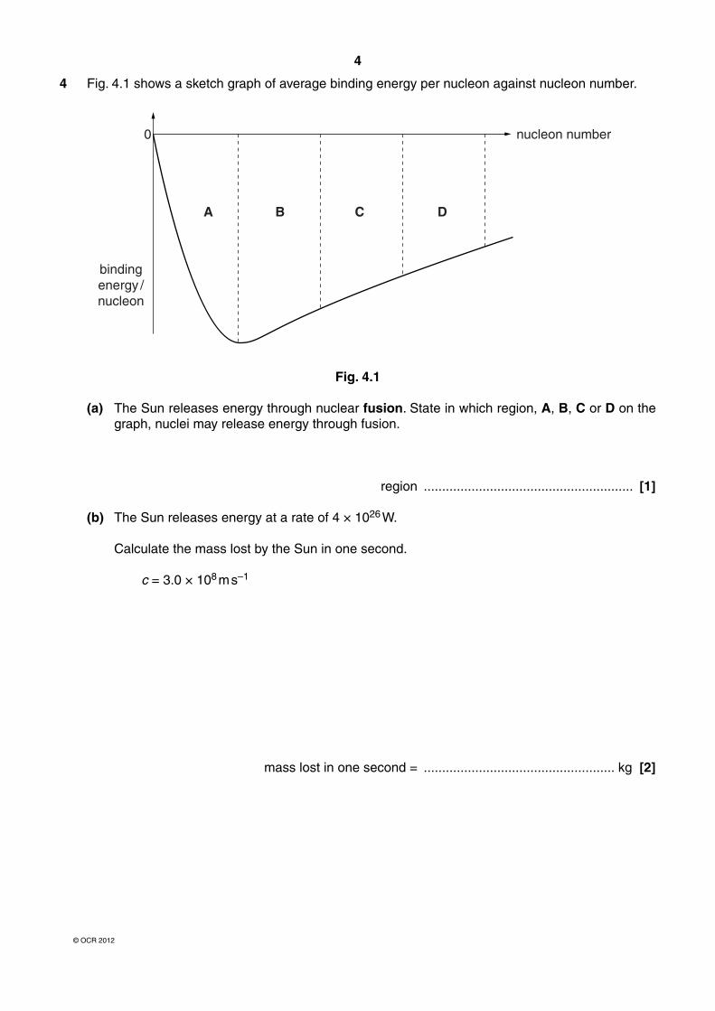
4 Fig. 4.1 shows a sketch graph of average binding energy per nucleon against nucleon number.
A
0
bindingenergy /nucleon
nucleon number
B C D
Fig. 4.1
(a) The Sun releases energy through nuclear fusion. State in which region, A, B, C or D on the graph, nuclei may release energy through fusion.
region ......................................................... [1]
(b) The Sun releases energy at a rate of 4 × 1026 W.
Calculate the mass lost by the Sun in one second.
c = 3.0 × 10⁸ m s–1
mass lost in one second = .................................................... kg [2]

5
Turn over© OCR 2012
5 Fig. 5.1 shows a point X near an isolated proton.
5.0 × 10⁻⁶ m
proton X
Fig. 5.1
The field strength at X, 5.0 × 10⁻⁶ m from the centre of the proton, is 58 N C–1.
(a) Calculate the potential at X. k = 9.0 × 10⁹ N m2 C–2
charge on a proton =1.6 × 10⁻¹⁹ C
potential = ................................................ J C–1 [2]
A second proton moves to a position as shown in Fig. 5.2.
5.0 × 10⁻⁶ m 5.0 × 10⁻⁶ m
proton protonX
Fig. 5.2
(b) State the field strength at X for the situation in Fig. 5.2.
[1]
(c) State how the potential at X in Fig. 5.2 compares with your answer to (a).
[1]

6
© OCR 2012
6 The centripetal force F on a charge q moving at right angles to a magnetic field is given by
F = q v B
where v is the speed of the particle in the field.
Combine this equation with that for centripetal force F = m v2 / r to show that a singly-charged ion of momentum 2.5 × 10⁻²⁰ kg m s–1 travelling at right angles to a magnetic field of strength 0.70 T will move in a circular path of radius about 0.2 m.
e = 1.6 × 10⁻¹⁹ C
[2]
7 In April 1986 the Chernobyl nuclear reactor released radioactive caesium-137 into the atmosphere. Caesium-137 has a half-life of 30.1 years.
Show that, in June 2012, approximately 26 years after the release, less than 60% of the caesium-137 remains.
[3]

7
Turn over© OCR 2012
8 Fig. 8.1 shows the direction of a current I in a wire at right angles to a field of flux density B.
BI
Fig. 8.1
Calculate the force on a 15 cm length of wire in a field of flux density 400 mT when the wire carries a current of 0.23 A.
force = ..................................................... N [2]
[Section A Total: 19]

8
© OCR 2012
Section B
9 This question is about the behaviour of electrons when passing near nuclei.
When an electron passes near a nucleus it is deflected as shown in Fig. 9.1.
nucleus
path ofelectron
Fig. 9.1
(a) Explain why the electron follows a path of the shape shown. You may add arrows to Fig. 9.1 indicating magnitude and direction of forces on the electron.
In your answer you should make clear how the force on the electron varies along its path.
[3]
(b) At high energies the momentum p of a particle is given by
p � Ec
where E is the energy of the particle and c is the speed of light.
(i) Show that Ec
has the units of momentum.
[2]

9
Turn over© OCR 2012
(ii) Show that an electron accelerated to a high energy of 6.8 × 10⁻¹¹ J (425 MeV) will have a de Broglie wavelength of about 3 × 10–15 m.
h = 6.6 × 10⁻³⁴ J s c = 3.0 × 10⁸ m s–1
[2]
(c) Fig. 9.2 shows how the number of 425 MeV electrons scattered by carbon nuclei varies with the scattering angle. The graph shows a clear diffraction minimum. The nuclei diffract high energy electrons like dust particles diffract light.
detector
accelerator
30100
101
102
103
104
105
40 50 60 70 80angle / degree
numberscattered /(arbitraryunits)
Fig. 9.2
The angle of the first diffraction minimum in such a pattern is given by the equation
sin θ = 1.2 λb
where b is the diameter of the diffracting object and λ is the wavelength of the electrons. Use data from the graph to estimate the diameter of the carbon nuclei in the sample.
diameter = ..................................................... m [3]
[Total: 10]

10
© OCR 2012
10 This question is about using accelerated protons in medicine.
The protons are accelerated to kinetic energies of 220 MeV. The rest energy of a proton is 940 MeV.
(a) (i) State what is meant by the term rest energy.
[1]
(ii) Show that the relativistic factor γ for these accelerated protons is about 1.2.
[1]
(iii) Show that these protons are travelling at about 0.6 c.
[2]
(b) In a medical procedure a cluster of cells of total mass 3.0 × 10⁻⁴ kg is irradiated with 220 MeV protons.
Show that it will take at least 105 protons to deliver an effective dose equivalent of 125 mSv to the cluster of cells.
e = 1.6 × 10⁻¹⁹ C quality factor of protons = 10
[3]

11
Turn over© OCR 2012
(c) The effect of a proton beam on tissue can be modelled by passing the proton beam through water. Energy is transferred from each proton when it ionises particles along its path. Fig. 10.1 shows how the energy of a proton beam varies along the path of the beam through water.
00
5 10 15 20 25penetration depth / cm
energy ofprotonbeam
Fig. 10.1
(i) Use information from the graph to estimate the depth at which the beam ionises the greatest number of particles per cm. Explain how you reached your answer.
depth = ......................................................... cm
[3]
(ii) Explain why the graph shows that your answer to (b) must be a minimum value.
[2]
[Total: 12]

12
© OCR 2012
11 This question is about using an electric field to deflect falling particles of material.
0 V + 48 kV
0.28 m
1.9 m
Fig. 11.1
Fig. 11.1 shows two vertical metal plates connected to a 48 kV supply.
(a) (i) Draw five lines to represent the electric field between the plates in Fig. 11.1. [2]
(ii) Add the 24 kV equipotential to the diagram. Label the line. [1]
(b) Use data from the diagram to show that field strength between the plates is about 0.2 MV m–1.
[1]

13
Turn over© OCR 2012
(c) A grain of mass 1.3 × 10⁻⁶ kg enters the region between the plates, falling at constant (terminal) vertical velocity of 0.8 m s–1. The grain carries an electric charge of +2.2 × 10⁻¹³ C.
(i) State why the data above suggests that the vertical force due to air drag is about 1 × 10⁻⁵ N.
g = 9.8 N kg–1
[1]
(ii) The horizontal force on the grain is much smaller. Show that the horizontal force is about 4 × 10⁻⁸ N.
[1]
(iii) Show that the horizontal distance moved by the grain as it falls through the 1.9 m plates is of the order of 0.1 m. Any horizontal drag forces can be ignored.
[3]
(d) Suggest and explain how the horizontal distance would change if the separation of the plates was doubled but all other factors remain constant.
[3]
[Total: 12]

14
© OCR 2012
12 This question is about magnetic circuits.
The permeance Λ of a magnetic circuit is given by the equation
Λ = ΦN I
where: Φ is the magnetic flux in the circuit N is the number of turns of the coil I is the current in the coil
A magnetic circuit is illustrated in Fig. 12.1.
data:I = 31 mAN = 150 turnsΦ = 4.6 × 10⁻⁶ Wb
cross-sectional area= 2.6 × 10⁻⁴ m2
length of magneticcircuit, L = 270 mm
Fig. 12.1
(a) Calculate the permeance of the circuit in Fig. 12.1.
permeance = .............................. unit .................... [2]
(b) The permeance of a magnetic circuit is also given by the equation
Λ = μAL
where μ is the permeability of the iron in the core, A the cross-sectional area of the core and L the length of the magnetic circuit.
Use data from Fig. 12.1 and your answer to (a) to calculate the permeability of the iron in the core.
permeability of iron in the core = ...................................... Wb A–1 m–1 [2]

15
Turn over© OCR 2012
(c) A crack develops across the core, making an air-gap running across its entire cross-section as shown in Fig. 12.2.
part ofcore
crack across core
Fig. 12.2
(i) State how the permeability of air compares to that of iron.
[1]
(ii) Explain why the flux through the core is reduced when the core develops a crack. You may find it useful to refer to an equation given earlier in the question.
[2]
(d) A student believes that the equation Λ = μA/L shows that the permeability of the iron in the core has also reduced. Discuss whether you agree with the student or not.
[2]
[Total: 9]
[Section B Total: 43]

16
© OCR 2012
Section C
These questions are based on the Advance Notice.
13 Explain how brittle fracture occurs in rocks under stress, starting at the cracks in the rock (lines 6–7 in the article). You may use diagrams in your answer.
[2]
[Total: 2]
14 Use the data given in Fig. 2 in the article to show that
(a) a surface wave L would take less than four hours to travel once around the circumference of the Earth
radius of Earth = 6400 km
[1]
(b) the P and S waves have the same wavelength.
[2]
[Total: 3]

17
Turn over© OCR 2012
15 Explain how a combination of transverse and longitudinal waves can result in vibrations in all three spatial directions (lines 9–10 in the article). You may find drawing a diagram useful in your answer.
[3]
[Total: 3]
16 A P wave travelling at 6.0 km s–1 meets a boundary between two rock types at an angle of incidence of 30° and passes through it at an angle of refraction of 21°.
Use the information given about wave refraction in Box 1 in the article to calculate the speed of the wave in the second type of rock.
speed = ................................................ m s–1 [3]
[Total: 3]

18
© OCR 2012
17 (a) Explain why it is important that the natural frequency of the seismometer is deliberately not equal to that of the vibrations caused by earthquakes.
[2]
(b) Show that the effective length L of the pendulum in a Milne seismometer (Figs. 3 and 4 in the article) needs to be about 100 m in order for it to have a frequency less than that of the lowest frequency waves (L waves, see Fig. 2 in the article).
natural frequency of a simple pendulum, f = 12π
gL
where g = 9.8 m s–2
[2]
(c) Hence calculate the angle α at which the boom needs to be tilted, if it has a length of 1.0 m.
α = .......................................... degrees [2]
[Total: 6]

19
Turn over© OCR 2012
18 Like many seismometers, the Milne design incorporates a large mass which ‘remains essentially motionless’ when the ground beneath it vibrates. Lines 42–43 in the article list the factors involved in ensuring that this occurs.
(a) Explain how the combination of a large mass and a small force ensures that the mass ‘remains essentially motionless’.
[2]
(b) Suppose you could have a pendulum of length 100 m. Explain why the accelerating force on the mass would be very small for a displacement of a few millimetres.
[2]
[Total: 4]

20
© OCR 2012
19 Earthquake magnitude can be measured using the Richter Scale (lines 52–54 in the article).
(a) Calculate how many times greater the shaking amplitude of a magnitude 6.0 earthquake is than one of magnitude 4.0. Explain how you reached your value.
answer ......................................................... [2]
(b) Using the relationship given in line 56 in the article, calculate how many times greater the energy released by a magnitude 6.0 earthquake is than one of magnitude 4.0.
answer ......................................................... [2]
[Total: 4]

21
Turn over© OCR 2012
20 The relative movement of the mass and base (Fig. 4 in the article) is detected using a magnet attached to the mass and a coil attached to the base.
(a) Explain how this movement can produce an emf.
[2]
(b) Here are some data for a particular magnet and coil arrangement used to detect vibrations in a seismometer (lines 45–48 in the article). The coil is square and its area is completely contained within the area of the uniform magnetic field at right angles to the plane of the coil.
strength of magnetic field = 0.15 T cross sectional area of coil = 4.0 cm2
number of coil turns = 200
(i) Show that the flux through the coil is greater than 5 × 10⁻⁵ Wb.
[2]
(ii) Hence calculate the flux linkage through the coil.
flux linkage = ......................................... Wb turns [1]

22
© OCR 2012
(iii) During an earthquake, the ground shakes. This causes the coil to move a distance of 3 mm out of the magnetic field at an average speed of 1.8 × 10⁻³ m s–1.
The flux linkage reduces to half its original value as the coil moves partially out of the magnetic field.
Calculate the magnitude of the emf induced in the coil as a result of this motion.
induced emf = ...................................................... V [4] [Total: 9]
21 The seismometer is damped to reduce unwanted vibration. One method of damping is mentioned in lines 66–68 in the article, using an aluminium plate moving in a magnetic field. With particular reference to induced voltage and energy transfers, describe how this arrangement produces the damping required.
You should make each step of your argument clear.
[4]
[Total: 4]
[Section C Total: 38]END OF QUESTION PAPER

23
© OCR 2012
BLANK PAGE
PLEASE DO NOT WRITE ON THIS PAGE

24
© OCR 2012
PLEASE DO NOT WRITE ON THIS PAGE
Copyright Information
OCR is committed to seeking permission to reproduce all third-party content that it uses in its assessment materials. OCR has attempted to identify and contact all copyright holders whose work is used in this paper. To avoid the issue of disclosure of answer-related information to candidates, all copyright acknowledgements are reproduced in the OCR Copyright Acknowledgements Booklet. This is produced for each series of examinations and is freely available to download from our public website (www.ocr.org.uk) after the live examination series.
If OCR has unwittingly failed to correctly acknowledge or clear any third-party content in this assessment material, OCR will be happy to correct its mistake at the earliest possible opportunity.
For queries or further information please contact the Copyright Team, First Floor, 9 Hills Road, Cambridge CB2 1GE.
OCR is part of the Cambridge Assessment Group; Cambridge Assessment is the brand name of University of Cambridge Local Examinations Syndicate (UCLES), which is itself a department of the University of Cambridge.