Embed Size (px)
Citation preview

MatSci 571: Molecules on Surfaces
Prof. K.W. HippsN116B Fulmer Hall
Spring 2014www.wsu.edu/~hipps/M571.htm

Molecules on Surfaces
• How we get them there.Deposition methods for ordered molecular films
Vapor DepositionLangmuir-Blodgett filmsSelf-Assembly from Solution and Vapor
• Scanning Probe Microscopy and Spectroscopy

Vapor Deposition
• Basic Vacuum TechnologyViscous versus ballistic (molecular) flow.When is the pressure low enough?Deposition methods (vapor sources).
• Types of AdsorptionPhysisorption and chemisorption
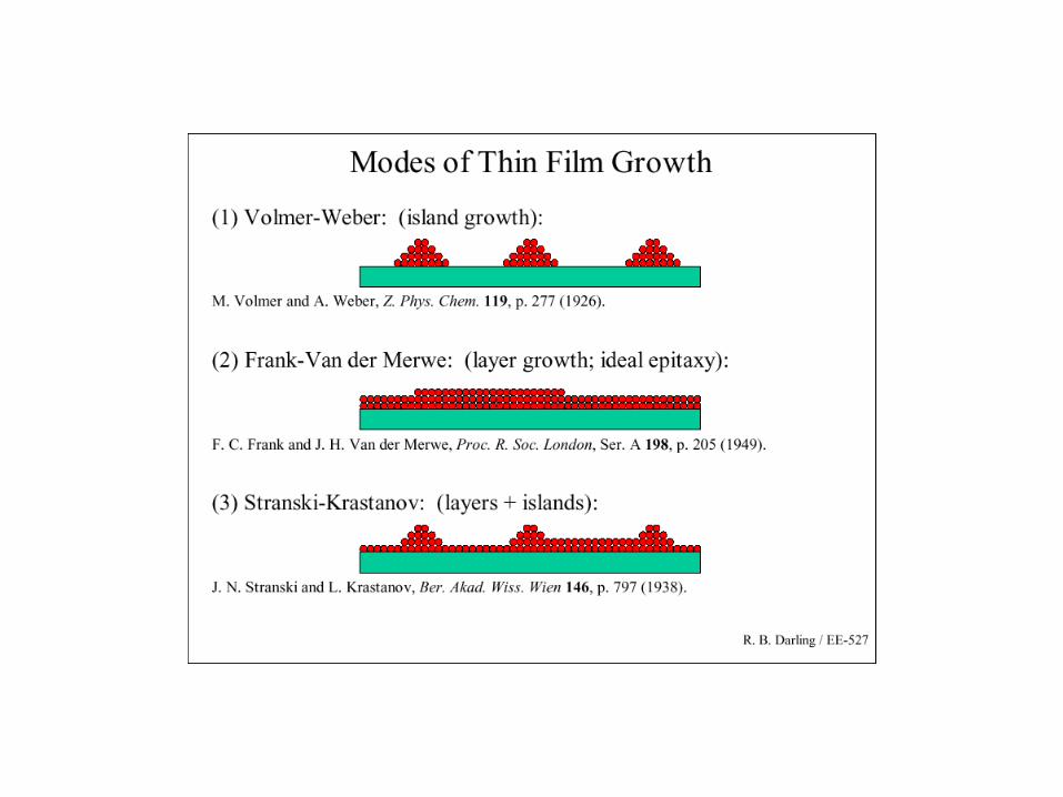
• Nucleation and Growth of Thin FilmsFrank-van der Merwe (layer-by-layer)Vollmer-Weber (island)Stranski-Krastanov (layer + island)
Viscous versus ballistic flow.Assume ideal gas: PV = nRT =NkT
P(atm), V(liter), n(moles), R(L-atm/mole-K), T(K)P(Pa), V(m3), N(molecules), k(J/molecule-K), T(K)1 atm = 1,013 mbar = 1.013 x 10⁵ Pa = 760 torr
The ‘Mean Free Path’ () is given by:(P) = kT/[Pd2] where all quantities are in mks unitsc(p) = 100kT/[0.133 pd2] : p in millitorr and c in cm
(cm)
P in millitorr
d = 0.2 nm T=300K
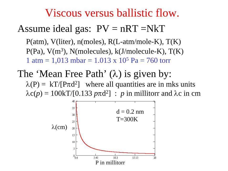
Viscous, Knudsen, and Ballistic FlowIf D is the diameter of a pipe:• Viscous flow:
<< D
Water in a pipe. The intermolecular interactions are much more important than the interactions with the container.P
50 milliTorr = 7 Pa = 5x10⁻² Torr
• Knudsen Flow DIntermediate state. About as many intermolecular collisions as collisons with the walls
• Ballistic Flow
>> D Bullets bouncing off walls. Negligible intermolecular interactions. Primary interactions are with the container.P
0.5 milliTorr = 0.07 Pa = 5x10⁻⁴ Torr

Impingement Rate• The number of molecules per second striking a
unit area is given by:
where Jc is molecules/cm2-sSince there are roughly 1015 atoms/cm2 on a typical metal surface, Jc /1015 is the frequency with which the entire surface experiences collisions from the gas phase. 1015/Jc is the time required for one complete surface encounter.
MRTPNJ A
c 210 4
MRT
PNJ A
2
P (torr) 1015/Jc(P)seconds
1015/Jc(P)hours
10-3 (1 millitorr) 2x10⁻³ ---10-5 0.3 ---10-7 26. 0.00710-9 2,600 0.7310-10 26,000 7.3
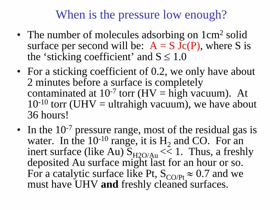
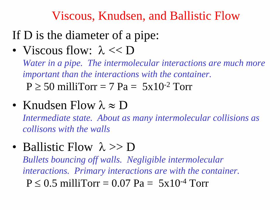
When is the pressure low enough?• The number of molecules adsorbing on 1cm2 solid
surface per second will be: A = S Jc(P), where S is the ‘sticking coefficient’ and S
1.0
• For a sticking coefficient of 0.2, we only have about 2 minutes before a surface is completely contaminated at 10-7 torr (HV = high vacuum). At 10-10 torr (UHV = ultrahigh vacuum), we have about 36 hours!
• In the 10-7 pressure range, most of the residual gas is water. In the 10-10 range, it is H2 and CO. For an inert surface (like Au) SH2O/Au << 1. Thus, a freshly deposited Au surface might last for an hour or so. For a catalytic surface like Pt, SCO/Pt
0.7 and we
must have UHV and freshly cleaned surfaces.

Deposition methods
• Chemical Vapor Deposition (CVD)• Ion beam and ion beam assisted deposition• RF and DC sputtering• Laser ablation deposition• Electron beam induced deposition• Thermal deposition
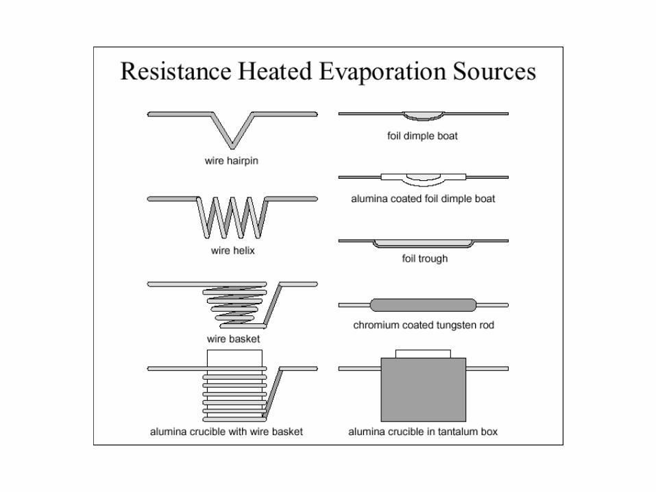
– Knudsen cell– open boats and filaments– baffled sources

One form of CVD deposition system
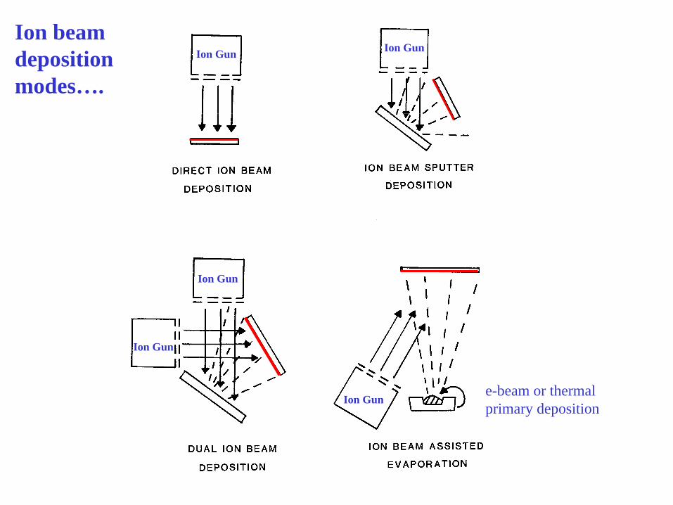
Ion Gun Ion Gun
Ion Gun
Ion Gun
Ion Gun
e-beam or thermal primary deposition
Ion beam deposition modes….

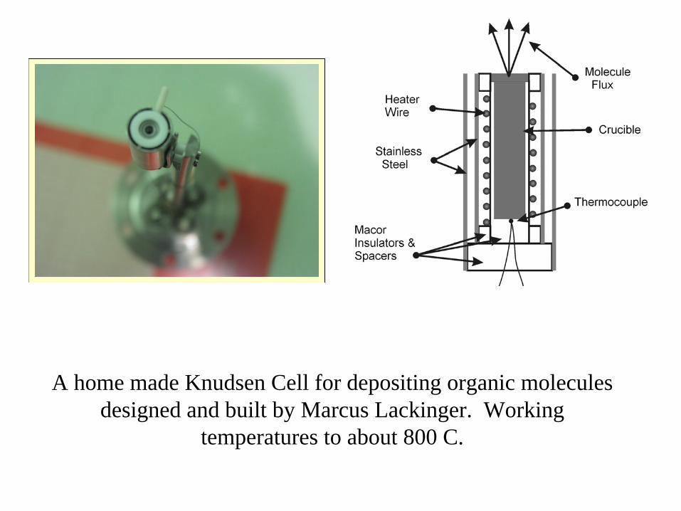
A home made Knudsen Cell for depositing organic molecules designed and built by Marcus Lackinger. Working
temperatures to about 800 C.
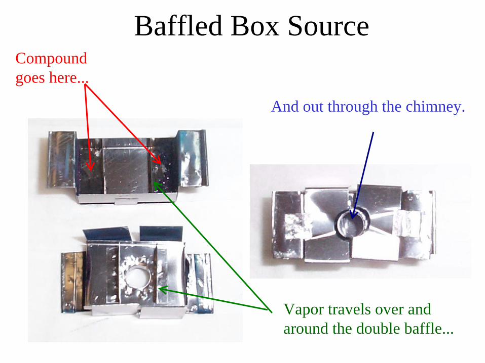
Baffled Box SourceCompound goes here...
Vapor travels over and around the double baffle...
And out through the chimney.
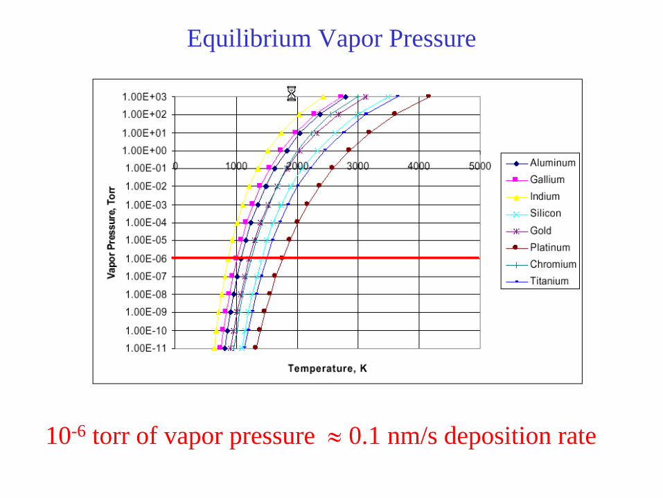
10-6 torr of vapor pressure
0.1 nm/s deposition rate
Equilibrium Vapor Pressure


Typical High Vacuum (HV) deposition system
Vacuum Pumping: Viscous versus Ballistic Flow
In order to achieve high or ultra high vacuum requires a transition from pressures where flow is viscous to pressures where flow is ballistic. This requires very different approaches. In the viscous flow regime (P
0.05 torr), a conventional
pump is used. Once the pressure drops into the ballistic flow region, such pumps are ineffective and those designed for compression just up to Knudsen flow pressures are used in conjunction with a viscous flow pump.
One speaks of ‘backing’ or ‘roughing’ the high vacuum (HV), or ultra-high vacuum (UHV) pump.
In order to achieve UHV conditions, one must account for the porosity and permeability of metals.

Pump-down Pressure vs Time for a Typical Unbaked Stainless Steel Chamber
10
10
10
10
10 10 1010 10 10 1010
10
-13
-10
-7
-4
1 3 5-1-1
-1
P (T
orr)
time (hours)
volume (e ) t
surface desorption (t )-1
diffusion (t )-1/2
permeation
[water, air, CO and CO ]2
[H and CO]
2
2
[H & He]
•The ultimate pressure of a particular system is achieved when the pumping rate just equals the rate of gas evolution.
• A recently opened system requires a very long time (or a very large pump) to achieve reasonable vacuum levels.
103 hrs is 42 days!!

What are the units for outgassing?
• q = total flux of gas molecules • = Pa-m3/(s-m2)• = W/m2
• = nRT/s-m2 = energy flow per unit area• q is proportional to mass flow if the
temperature is constant
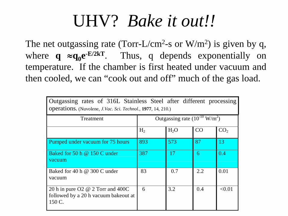
UHV? Bake it out!!The net outgassing rate (Torr-L/cm2-s or W/m2) is given by q, where q q0 e-E/2kT. Thus, q depends exponentially on temperature. If the chamber is first heated under vacuum and then cooled, we can “cook out and off” much of the gas load.
Outgassing rates of 316L Stainless Steel after different processingoperations. (Nuvolene, J.Vac. Sci. Technol., 1977, 14, 210.)
Treatment Outgassing rate (10-10 W/m2)
H2 H2O CO CO2
Pumped under vacuum for 75 hours 893 573 87 13
Baked for 50 h @ 150 C undervacuum
387 17 6 0.4
Baked for 40 h @ 300 C undervacuum
83 0.7 2.2 0.01
20 h in pure O2 @ 2 Torr and 400Cfollowed by a 20 h vacuum bakeout at150 C.
6 3.2 0.4 <0.01

Pumps for Vacuum Systems• High Vacuum
2-stage pumping requiredGenerally no bake-outRoughing pump backing:
- diffusion pump- turbo pump- cryopump
10-5 to 10-8 torr
• Ultra-High Vacuum3-stage pumping requiredBake-out is essentialRoughing pump backing:
- turbo pump- cryopump
Ion pump operating alone after bake-out
10-9 to 10-11 torr
TS
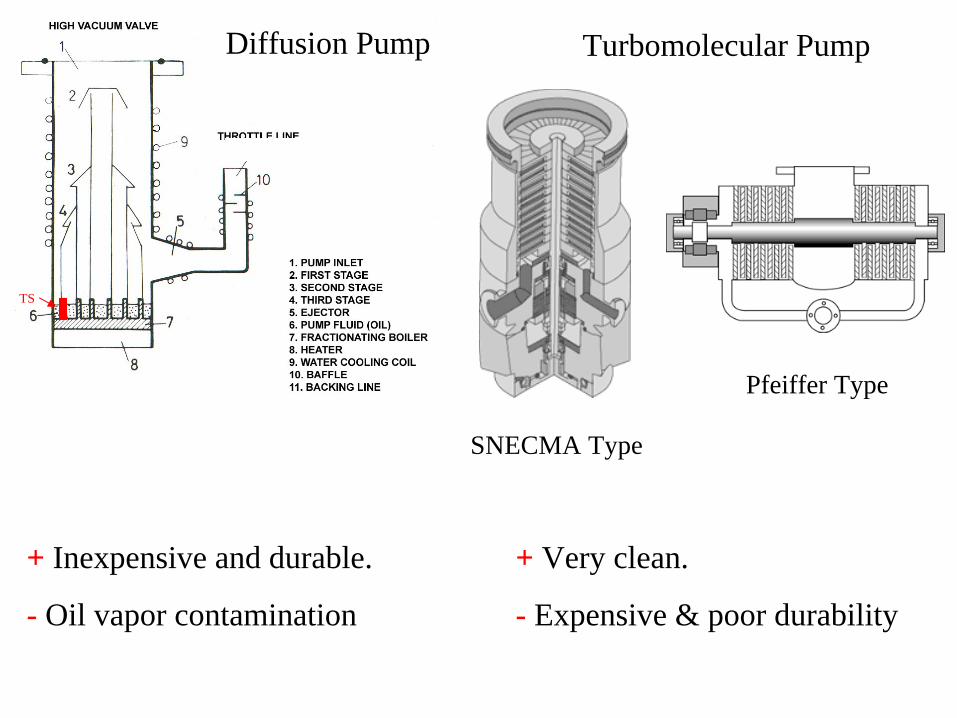
Diffusion Pump
Pfeiffer Type
SNECMA Type
Turbomolecular Pump
+ Inexpensive and durable.
- Oil vapor contamination
+ Very clean.
- Expensive & poor durability
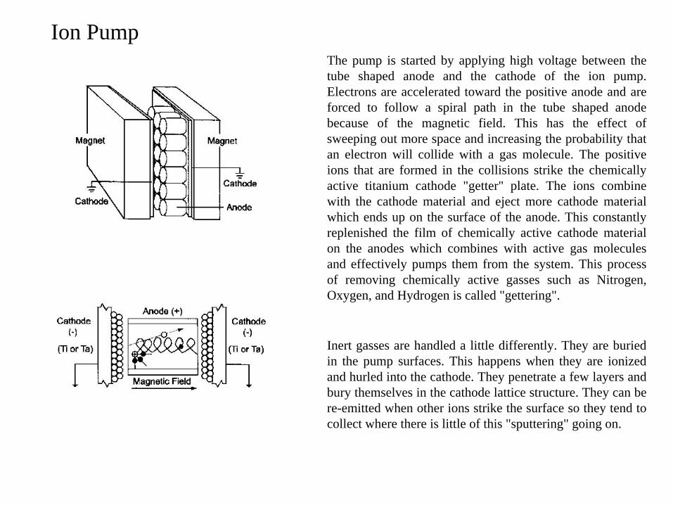
The pump is started by applying high voltage between the tube shaped anode and the cathode of the ion pump. Electrons are accelerated toward the positive anode and are forced to follow a spiral path in the tube shaped anode because of the magnetic field. This has the effect of sweeping out more space and increasing the probability that an electron will collide with a gas molecule. The positive ions that are formed in the collisions strike the chemically active titanium cathode "getter" plate. The ions combine with the cathode material and eject more cathode material which ends up on the surface of the anode. This constantly replenished the film of chemically active cathode material on the anodes which combines with active gas molecules and effectively pumps them from the system. This process of removing chemically active gasses such as Nitrogen, Oxygen, and Hydrogen is called "gettering".
Inert gasses are handled a little differently. They are buried in the pump surfaces. This happens when they are ionized and hurled into the cathode. They penetrate a few layers and bury themselves in the cathode lattice structure. They can be re-emitted when other ions strike the surface so they tend to collect where there is little of this "sputtering" going on.
Ion Pump
Essential Accessories
• RGA: Residual gas analyzer: How clean is your system and what are you depositing?
• Quartz crystal thin film monitor: How fast is your film growing and how thick is it?
• Shutters and shields: Control where the vaporized material goes.
• Gauging: Bayard-Alpert for UHV, thermocouple for backing pressure,…
• Sample heating, cooling, and temperature control: Its hard to in a vacuum!
Vapor Deposition
• Basic Vacuum TechnologyViscous versus ballistic flow.When is the pressure low enough?Deposition methods (vapor sources).
• Types of AdsorptionPhysisorption and chemisorption
• Nucleation and Growth of Thin FilmsFrank-van der Merwe (layer-by-layer)Vollmer-Weber (island)Stranski-Krastanov (layer + island)
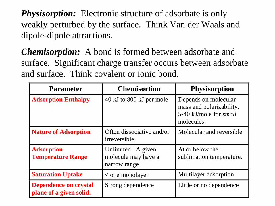
Parameter Chemisortion PhysisorptionAdsorption Enthalpy 40 kJ to 800 kJ per mole Depends on molecular
mass and polarizability.5-40 kJ/mole for smallmolecules.
Nature of Adsorption Often dissociative and/orirreversible
Molecular and reversible
AdsorptionTemperature Range
Unlimited. A givenmolecule may have anarrow range
At or below thesublimation temperature.
Saturation Uptake one monolayer Multilayer adsorption
Dependence on crystalplane of a given solid.
Strong dependence Little or no dependence
Physisorption: Electronic structure of adsorbate is only weakly perturbed by the surface. Think Van der Waals and dipole-dipole attractions.
Chemisorption: A bond is formed between adsorbate and surface. Significant charge transfer occurs between adsorbate and surface. Think covalent or ionic bond.

Typical low coverage image of an organometallic on Au(111)

A monolayer of cobalt(II)phthalocyanine on Au(111)

Multilayer coverage (~ 1.6 monolayer) of MPc on Au(111)
monolayer
2nd layer3rd layer

Tribology & Surface Science Branch NASA Glenn Research Center
The buffer layer method, described by Weaver et al., is useful in growing quantum dots.
Spiral growth step of SiC surface formed by layer growth (Frank-Van der Merwe)
Island growth of Fe clusters (Volmer-Weber)

Self-Assembled Surface Structures
• Pressure Assisted Organized Films: Langmuir-Blodgett films
• Self-Assembled Chemisorbed Monolayers • Vertical Self-Assembly with Lateral Disorder• Self-Assembled Physisorbed Monolayers
a) van der Waals (only) lateral interactionsb) Supramolecular Structure - non-covalent
interactions
• Structure Identification through Scanning Probe Imaging and Spectroscopy.

Langmuir-Blodgett (LB) Films
Topics:
• Introduction to LB films
• Making LB Films
•Selected Examples of LB Films

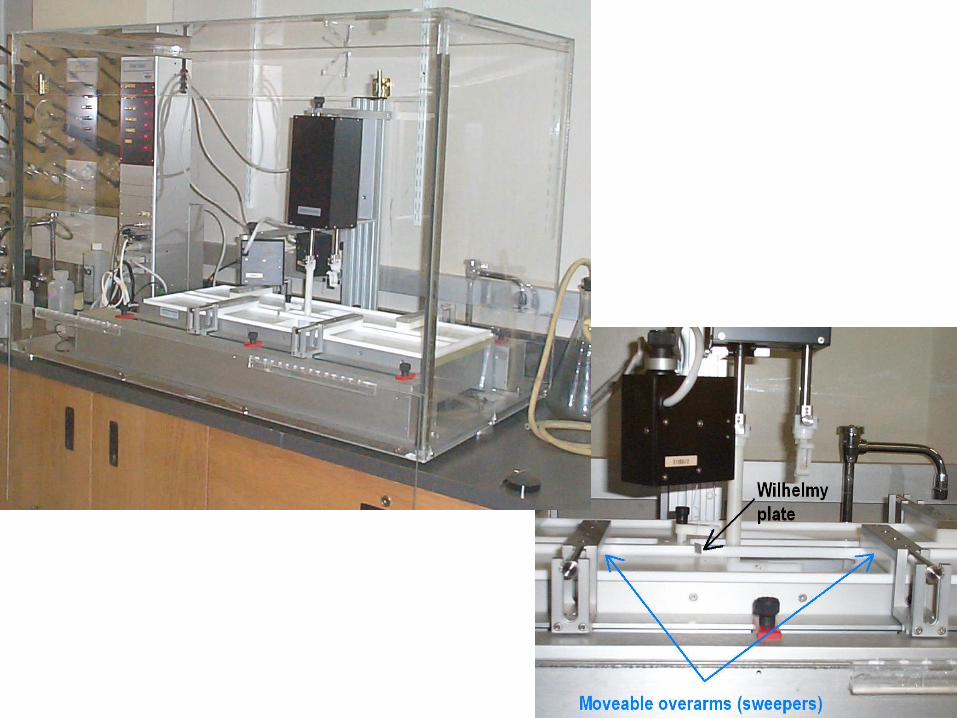
Langmuir-Blodgett Film: a mechanically assembled monomolecular array of (usually amphiphilic) molecules on an aqueous subphase (typically). Once the molecules become compressed to the desired organization, the resulting monolayer film can be transferred onto a solid substrate.
An amphiphilic molecule possesses one end that is hydrophilic and the other that is hydrophobic.
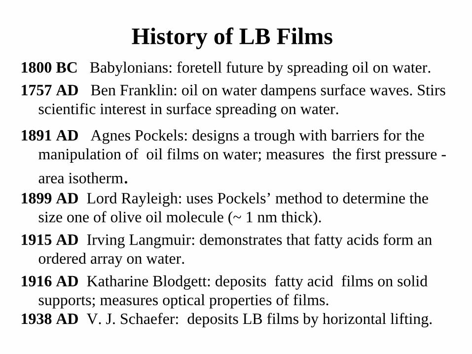
History of LB Films1800 BC Babylonians: foretell future by spreading oil on water.1757 AD Ben Franklin: oil on water dampens surface waves. Stirs
scientific interest in surface spreading on water.
1891 AD Agnes Pockels: designs a trough with barriers for the manipulation of oil films on water; measures the first pressure - area isotherm.
1899 AD Lord Rayleigh: uses Pockels’ method to determine the size one of olive oil molecule (~ 1 nm thick).
1915 AD Irving Langmuir: demonstrates that fatty acids form an ordered array on water.
1916 AD Katharine Blodgett: deposits fatty acid films on solid supports; measures optical properties of films.
1938 AD V. J. Schaefer: deposits LB films by horizontal lifting.
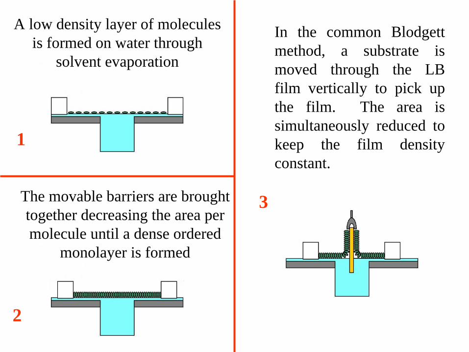
A low density layer of molecules is formed on water through
solvent evaporation
The movable barriers are brought together decreasing the area per molecule until a dense ordered
monolayer is formed
In the common Blodgett method, a substrate is moved through the LB film vertically to pick up the film. The area is simultaneously reduced to keep the film density constant.
1
2
3
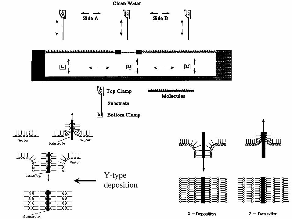
Y-type deposition
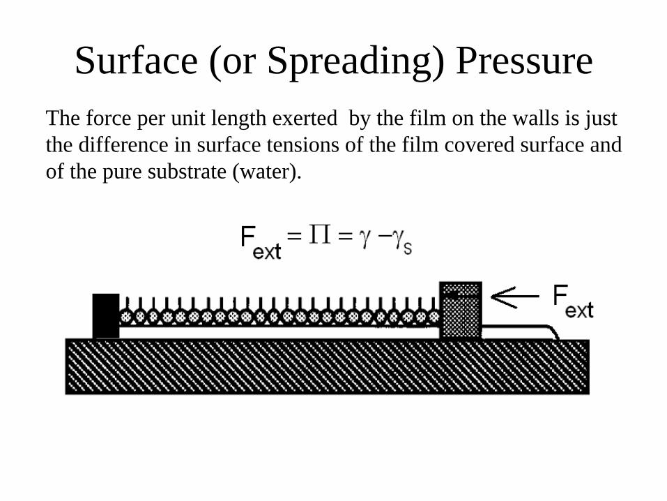
Surface (or Spreading) Pressure The force per unit length exerted by the film on the walls is just the difference in surface tensions of the film covered surface and of the pure substrate (water).

Roberts: Langmuir-Blodgett Films
Surface pressure/area isotherm for Stearic Acid at 22°C
“gas” phase
“liquid” phase
“solid” phase
Area/molecule
Surfa
ce P
ress
ure,
Pockels Point
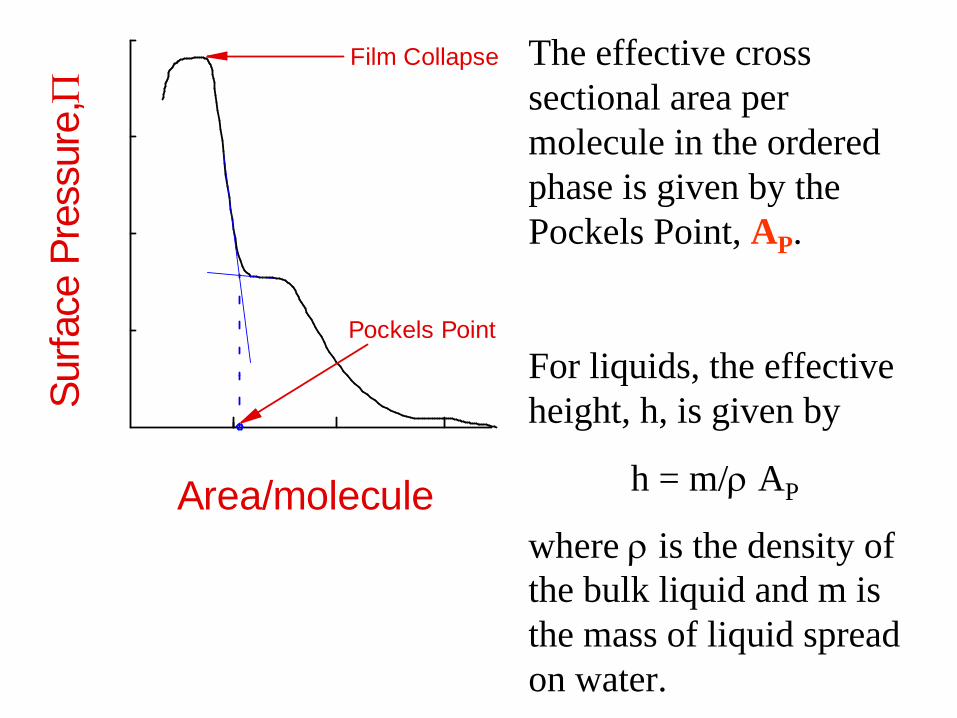
Film Collapse The effective cross sectional area per molecule in the ordered phase is given by the Pockels Point, AP .
For liquids, the effective height, h, is given by
h = m/
AP
where
is the density of the bulk liquid and m is the mass of liquid spread on water.
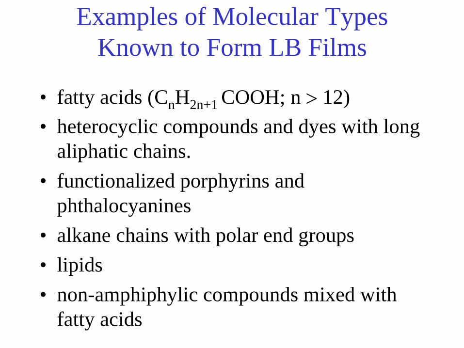
Examples of Molecular Types Known to Form LB Films
• fatty acids (Cn H2n+1 COOH; n
12)• heterocyclic compounds and dyes with long
aliphatic chains.• functionalized porphyrins and
phthalocyanines• alkane chains with polar end groups• lipids• non-amphiphylic compounds mixed with
fatty acids
N
NN N
NN
NCu
N
ORRO
OR
OR
ORRO
RO
RO
N
NN N
NN
NCu
N
ORRO
OR
OR
OR
OR
OR
RO
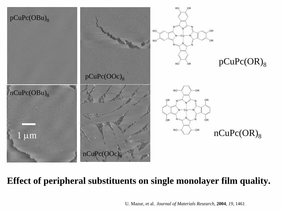
pCuPc(OBu)8 pCuPc(OOc)8
nCuPc(OOc)8
nCuPc(OBu)8
1 m
pCuPc(OR)8
nCuPc(OR)8
Effect of peripheral substituents on single monolayer film quality.
U. Mazur, et al. Journal of Materials Research, 2004, 19, 1461
pCuPc(OBu)8
pCuPc(OOc)8
nCuPc(OOc)8
nCuPc(OBu)8

Mechanical Properties of 10 monolayer CuPc based LB films and selected materials.
Material Young's modulus (GPa) Hardness (GPa)pCuPc(OBu)pCuPc(OBu) 88 /W (/W (nanoindenternanoindenter) ) 8383 0.600.60pCuPc(OBu)8 /mica (AFM) 110pCuPc(OOc)8 /W (nanoindenter) 71 0.60nCuPc(OOc)8 /W (nanoindenter) 63 0.52
Copper* 130 0.6AluminumAluminum** ++ 7070 0.4 (film on Si)0.4 (film on Si)Magnesium* 45 0.3
Polyethylene 3 0.1*http://environmentalchemistry.com/yogi/periodic/; + Oring, “Materials Science of Thin Films”, 2002
Single monolayer separations!
Single monolayer indent.
U. Mazur, et al. Journal of Materials Research, 2004, 19, 1461

AFM image of a single monolayer on
mica.
J. Tachibana et al. J. Luminescence 87-89 (2000) 800-802.

Self-Assembled Surface Structures
• Pressure Assisted Organized Films: Langmuir-Blodgett films
• Self-Assembled Chemisorbed Monolayers • Vertical Self-Assembly with Lateral Disorder• Self-Assembled Physisorbed Monolayers
a) van der Waals (only) lateral interactionsb) Supramolecular Structure - non-covalent
interactions
• Structure Identification through Scanning Probe Imaging and Spectroscopy.
Self-Assembled FilmsSelf-assembly has become one of the holy grails of
nanotechnology, and scientists in numerous labs are working to transform it into an effective nano-engineering tool.
In some sense, self-assembly is nothing new: biology does it all the time. Moreover, "supramolecular" chemistry has been studied for decades, showing how molecules can team up to form new non-covalent structures. The concept of self-assembly largely grew out of chemists' attempts to make molecules that aggregated spontaneously into specific configurations, in the same way biological molecules form complex cell membranes.

A Self Assembled Monolayer (SAM) is an ordered molecular assembly formed by the spontaneous adsorption of a molecular species. This adsorption might take place from vapor, liquid, or from solution depending on the adsorbate and the surface. Although the field is not limited to long chain molecules (we will see lots of other types), functionalized long chain hydrocarbons are most frequently used as the building blocks of these supramolecular thin film structures.
Thus, a typical SAM is formed from long chain organic molecules with a reactive group at one end that can undergo a specific chemical reaction with a substrate.
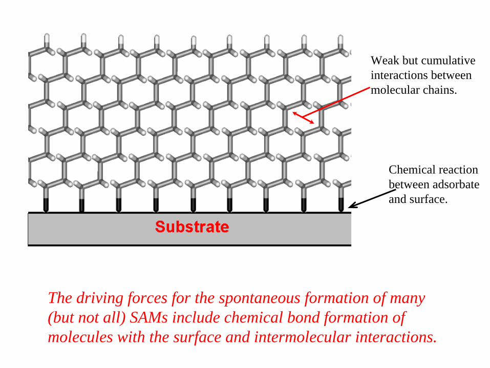
The driving forces for the spontaneous formation of many (but not all) SAMs include chemical bond formation of molecules with the surface and intermolecular interactions.
Chemical reaction between adsorbate and surface.
Weak but cumulative interactions between molecular chains.
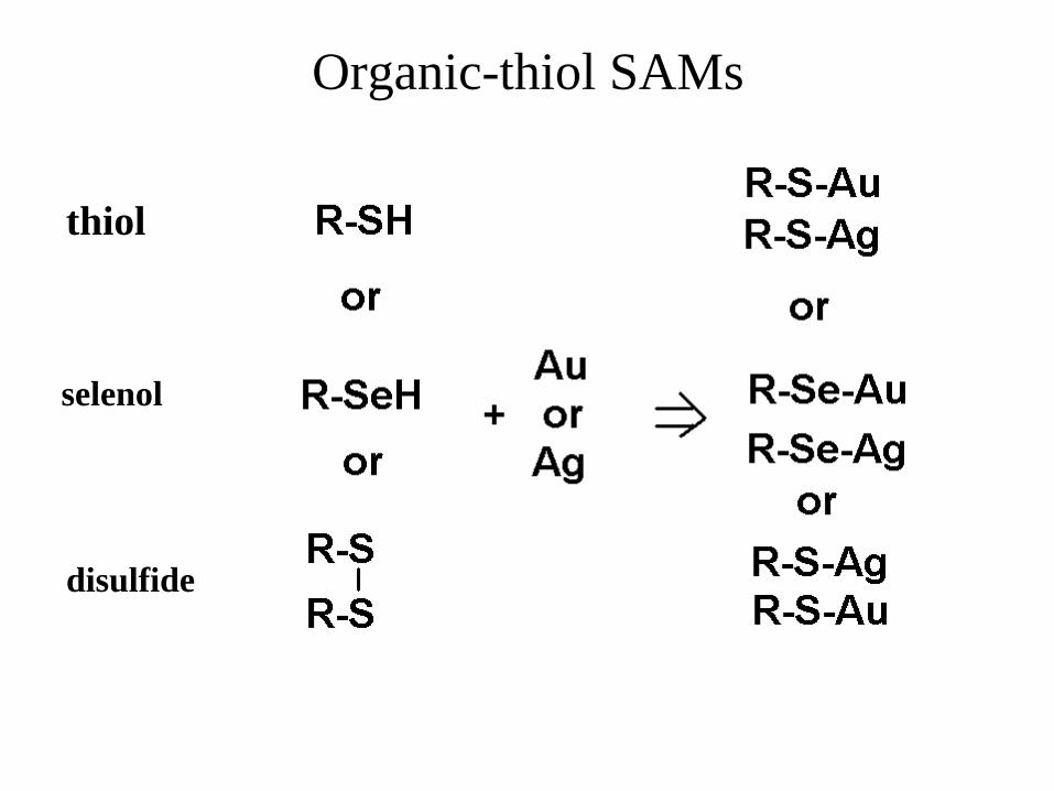
Organic-thiol SAMs
thiol
selenol
disulfide

Typical Alkyl-Thiol SAM Formation
The terminal alkane end can be easily functionalized in order to provide a designed surface chemistry. (At a few sites, or all of them)

SAMs can also be formed on oxides!
CH3 (CH2 )n CO2 H Adsorbed on Oxide Surfaces
OO - OO - OO -AgOAl O2 3
OO
OO
OO
OO
---- OO -OO
-
27°
Surface acid-base reaction with elimination of water.
Ulman, Chem. Rev. 1996, 96, 153

Silanes are also very active in forming SAMs on oxide surfaces. Like alkyl-thiols, they can be terminally functionalized and used as-is for specific chemistry or can become the base for a multi-layer SAM. They can be adsorbed from liquid or vapor but form only partially ordered layers

Self-Assembled Surface Structures
• Pressure Assisted Organized Films: Langmuir-Blodgett films
• Self-Assembled Chemisorbed Monolayers • Vertical Self-Assembly with Lateral Disorder• Self-Assembled Physisorbed Monolayers
a) van der Waals (only) lateral interactionsb) Supramolecular Structure - non-covalent
interactions
• Structure Identification through Scanning Probe Imaging and Spectroscopy.
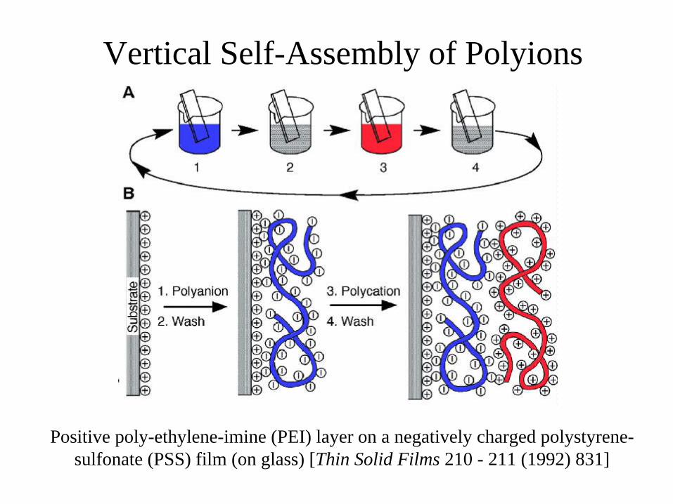
Vertical Self-Assembly of Polyions
Positive poly-ethylene-imine (PEI) layer on a negatively charged polystyrene- sulfonate (PSS) film (on glass) [Thin Solid Films 210 - 211 (1992) 831]

Self-assembly of nonlinear optical molecules into acentric films. The nonlinear optical molecules are end-capped by a hydrogen-bond acceptor group (pyridine) at one end and a hydrogen-bond donor (carboxylic acid) at the other end. Through hydrogen bonding, these molecules self-assemble into head-to-tail geometries.
Nature Materials (2004) 3, 841-843Nature Materials (2004) 3, 910-917

Contact-mode AFM images of self-organized acentric films. Topographs refer to scan areas of 5 x 5 m2 on a silicon substrate for films of thickness: a, 400 nm (r.m.s. = 0.37 nm) and b, 1,470 nm (r.m.s. = 8.68 nm).
Nature Materials (2004) 3, 910-917
These films are much rougher than the idealized picture used to describe their formation.

Self-Assembled Surface Structures
• Pressure Assisted Organized Films: Langmuir-Blodgett films
• Self-Assembled Chemisorbed Monolayers • Vertical Self-Assembly with Lateral Disorder• Self-Assembled Physisorbed Monolayers
a) van der Waals (only) lateral interactionsb) Supramolecular Structure - non-covalent
interactions
• Structure Identification through Scanning Probe Imaging and Spectroscopy.
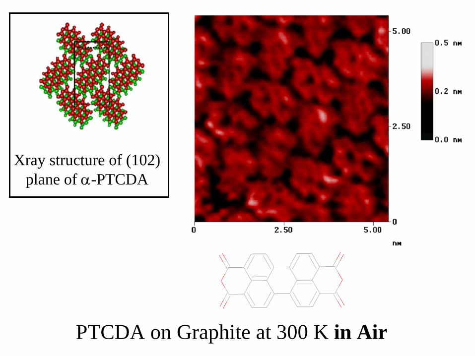
PTCDA on Graphite at 300 K in Air
Xray structure of (102) plane of -PTCDA

A monolayer of cobalt(II)phthalocyanine on Au(111):
X. Lu et al. J. Amer. Chem. Soc.,1996, 118, 7197
Supramolecular Chemistry• Molecules as building blocks. Supramolecular chemistry is chemistry that uses molecules rather than atoms as building blocks.
• In molecular chemistry, covalent and ionic bonds are used to assemble atoms into molecules. In the supramolecular case, supramolecular assemblies are held together by are weaker noncovalent interactions, such as hydrogen bonding, polar attractions, -
stacking, van der Waals forces, and
hydrophilic–hydrophobic interactions.
• Traditional chemistry ~ 1nm; Supramolecular chemistry >> 1 nm (can be macroscopic).
• Supramolecular chemistry is essential for biology (life) and holds the key for bottom up formation of nanostructures and the creation of new materials.

Nature is the Premier Supramolecular
Chemist

Supramolecular design
isophthalic acid

2D supramolecular architecture•Use the idea of weak interactions producing designed structures borrowed from 3D.
•Dramatically enhance design control by removing a degree of freedom through physisorption on a support.
•Use a conducting support so that there is image charge stabilization of adsorbed species.
•This can work both from solution and UHV -- chemistry in a beaker or a deposition system.
•A key element for the development of self-assembling (bottom up) nano-structured films.

Image Charges at Conductor SurfacesThe parallel electric field at the surface of a conductor must vanish. Thus, the electric field lines at a metal surface are normal to the surface. One way to get the correct field solution without the work of solving Poison’s equation, is to use the image charge model:
Thus, a dipole moment or partial charge on a molecule produces an opposite one across the conductor surface. These opposing dipoles or charges lead to attraction between the adsorbate and the surface. Even when the molecule is uncharged and has no permanent dipole moment!

Supramolecular Chemistry {Self-assembly} at the solid-
vapor interface.

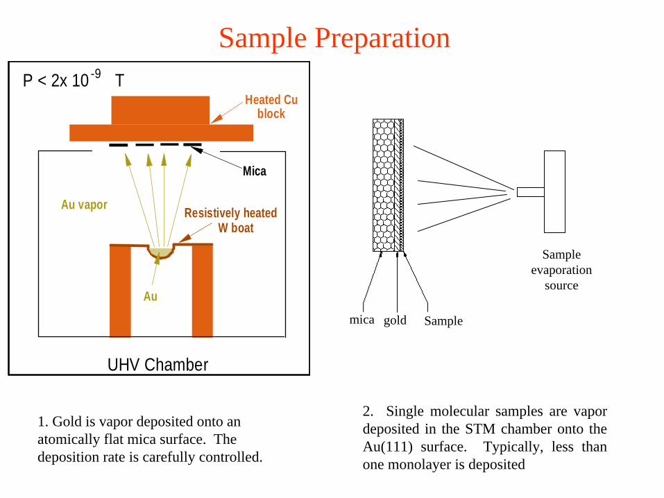
Sample Preparation
1. Gold is vapor deposited onto an atomically flat mica surface. The deposition rate is carefully controlled.
2. Single molecular samples are vapor deposited in the STM chamber onto the Au(111) surface. Typically, less than one monolayer is deposited
mica gold Sample
Sample evaporation
sourceAu
Resistively heated
Mica
Au vapor
Heated CuP < 2x 10 T-9
UHV Chamber
block
W boat

Griessl et al., Single Mol. 3 (2002) 25from UHV on graphite

Design a bimolecular 2D self-assembled structure from the vapor
• Use organic semiconductors to make the material interesting.• F…H interactions should be the basis for a good synthon• Need thermally stable compounds that can be vapor deposited.• Very low vapor pressure (at room T) materials best so they stick to the substrate by physisorption.• Molecule-substrate interaction must NOT result in covalent bond.• Molecule-molecule interaction must NOT result in covalent bond.•Substrate should be a metal to maximize non-covalent interactions.•Use Scanning Tunneling Microscopy (STM) to characterize these interface structures.• Need to label the components somehow so we can tell them apart.
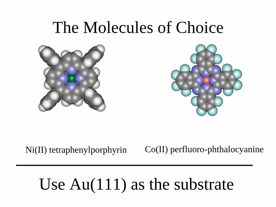
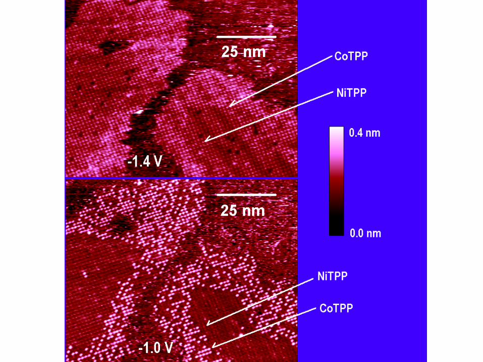
The Molecules of Choice
Ni(II) tetraphenylporphyrin Co(II) perfluoro-phthalocyanine
Use Au(111) as the substrate
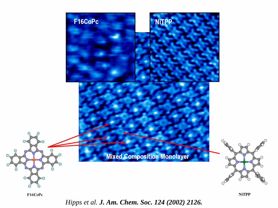
Hipps et al. J. Am. Chem. Soc. 124 (2002) 2126.
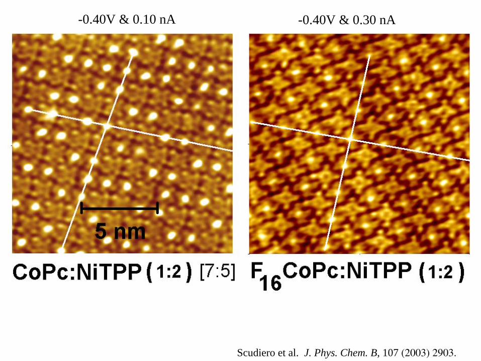
-0.40V & 0.10 nA -0.40V & 0.30 nA
Scudiero et al. J. Phys. Chem. B, 107 (2003) 2903.
Self-assembly at the solid- solution interface.

Tetradecanol [CH3 (CH2 )13 OH] on
Graphite
OH…OH
Claypool et al., J. Phys. Chem. B 101 (1997) 5978
Van der Waals interactions in the plane can produce self-assembling films for physisorbed systems.

25x25 nm constant current STM image of the interface between graphite and a solution of TMA, coronene, and heptanoic acid. The
insert is a correlation average.

25x25 nm STM image of the interface between Au(111) and a solution of coronene in heptanoic
acid. 700 pA and -600 mV sample bias
3D view of a correlation average STM image. Z range is about
0.3 nm
Supramolecular Structures of Coronene and Alkane Acids at the Au(111) - Solution interface: A Scanning Tunneling Microscopy Study. Brett Gyarfas,
Bryan Wiggins, Monica Zosel, and K. W. Hipps. Langmuir; 2004; ASAP Article; DOI: 10.1021/la047726j .

CPK models of heptanoic acid and coronene
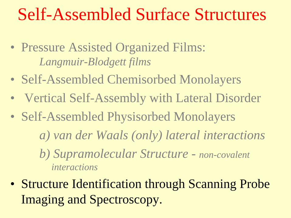
Self-Assembled Surface Structures
• Pressure Assisted Organized Films: Langmuir-Blodgett films
• Self-Assembled Chemisorbed Monolayers • Vertical Self-Assembly with Lateral Disorder• Self-Assembled Physisorbed Monolayers
a) van der Waals (only) lateral interactionsb) Supramolecular Structure - non-covalent
interactions
• Structure Identification through Scanning Probe Imaging and Spectroscopy.
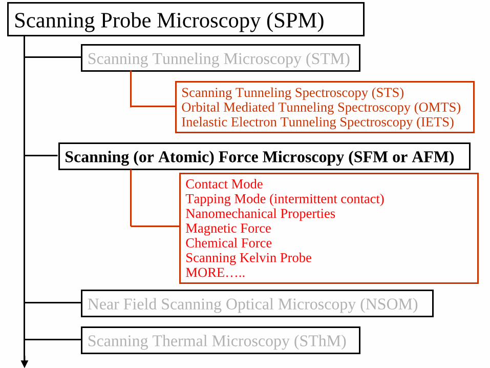
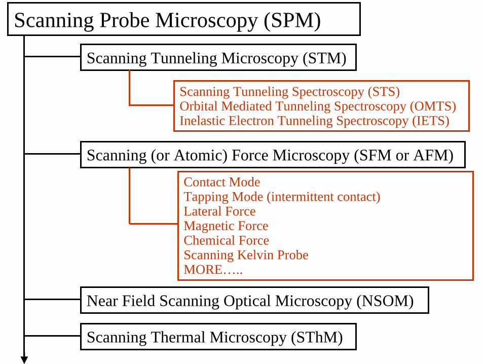
Scanning Probe Microscopy (SPM)
Scanning Tunneling Microscopy (STM)
Scanning (or Atomic) Force Microscopy (SFM or AFM)
Near Field Scanning Optical Microscopy (NSOM)
Scanning Thermal Microscopy (SThM)
Scanning Tunneling Spectroscopy (STS)Orbital Mediated Tunneling Spectroscopy (OMTS)Inelastic Electron Tunneling Spectroscopy (IETS)
Contact Mode Tapping Mode (intermittent contact)Nanomechanical PropertiesMagnetic Force Chemical ForceScanning Kelvin ProbeMORE…..
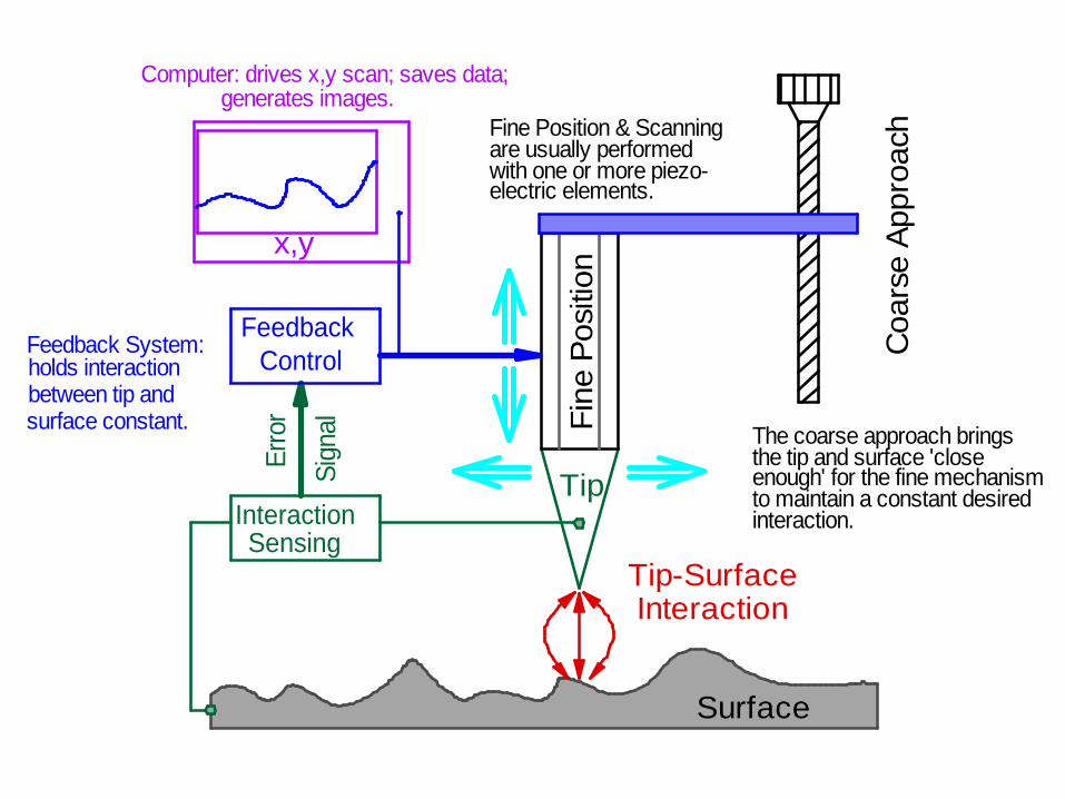
Tip-Surface Interaction
Surface
Tip
Fine
Pos
ition
Coa
rse
Appr
oach
InteractionSensing
FeedbackControl
Erro
r
Sign
al
x,y
Computer: drives x,y scan; saves data; generates images.
Feedback System:holds interactionbetween tip and surface constant. The coarse approach brings
the tip and surface 'closeenough' for the fine mechanism to maintain a constant desiredinteraction.
Fine Position & Scanningare usually performed with one or more piezo-electric elements.
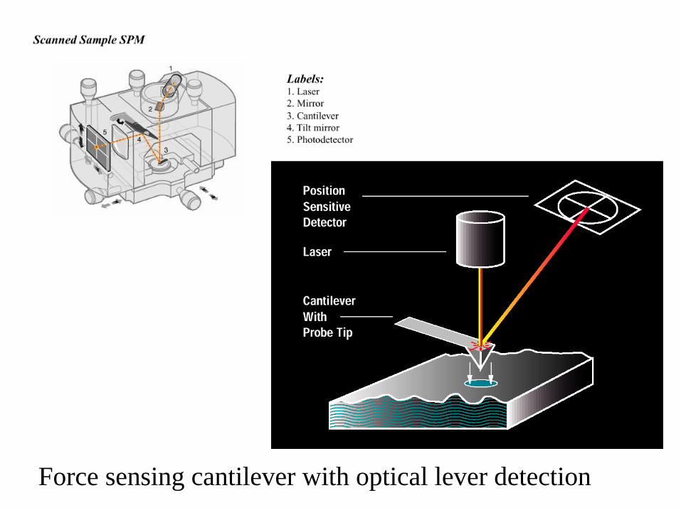
Force sensing cantilever with optical lever detection

Si3 N4 ~0.1 N/m Si ~ 50 N/m
Four Si3N4 cantilevers on a single glass chip. Force constants in Newtons/m. Side Wall angles = 35º.
1 mm
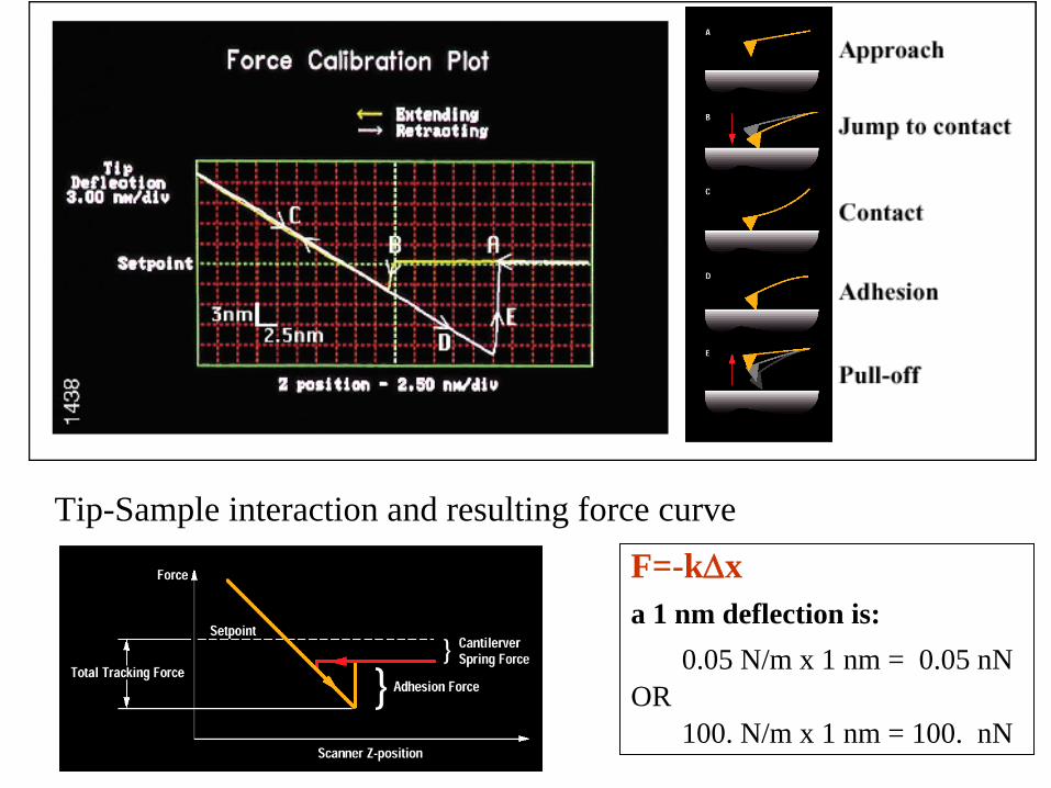
Tip-Sample interaction and resulting force curveF=-kxa 1 nm deflection is:
0.05 N/m x 1 nm = 0.05 nNOR
100. N/m x 1 nm = 100. nN
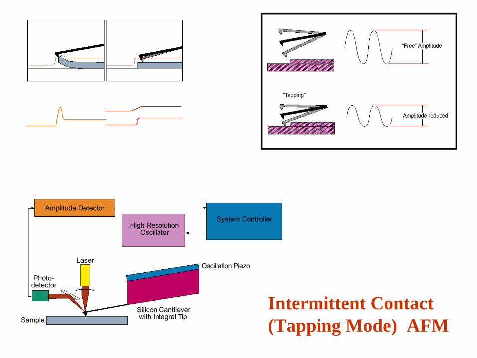
Intermittent Contact (Tapping Mode) AFM
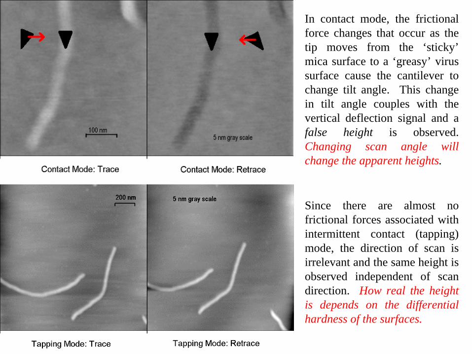
In contact mode, the frictional force changes that occur as the tip moves from the ‘sticky’ mica surface to a ‘greasy’ virus surface cause the cantilever to change tilt angle. This change in tilt angle couples with the vertical deflection signal and a false height is observed. Changing scan angle will change the apparent heights.
Since there are almost no frictional forces associated with intermittent contact (tapping) mode, the direction of scan is irrelevant and the same height is observed independent of scan direction. How real the height is depends on the differential hardness of the surfaces.

FIG X5. Young’s modulus determination and results on highly ordered pyrrolytic graphite (HOPG). (a) Retract curve of an example ramp on HOPG with zero separation set at the point of of maximum adhesion, sm (DMT model). 1 Hz ramp, 750 mV trigger threshold, 200 nm ramp size, 2048 pts per line, 32 degree x-rotate. The red squares show the retract curve. The red boxes show the top 80 percent fit region. The black line shows the DMT fitted curve. (b) Young’s modulus values on HOPG as a function of maximum tip force (FTip).
FTip = 4/3 E* (RTip )1/2 (i)3/2 + Fadh
Derjaguin, Muller, and Toporov (DMT) model
Scanning Probe Microscopy (SPM)
Scanning Tunneling Microscopy (STM)
Scanning (or Atomic) Force Microscopy (SFM or AFM)
Near Field Scanning Optical Microscopy (NSOM)
Scanning Thermal Microscopy (SThM)
Scanning Tunneling Spectroscopy (STS)Orbital Mediated Tunneling Spectroscopy (OMTS)Inelastic Electron Tunneling Spectroscopy (IETS)
Contact Mode Tapping Mode (intermittent contact)Lateral ForceMagnetic Force Chemical ForceScanning Kelvin ProbeMORE…..

Tip-Surface Interaction
Surface
Tip
Fine
Pos
ition
Coa
rse
Appr
oach
InteractionSensing
FeedbackControl
Erro
r
Sign
al
x,y
Computer: drives x,y scan; saves data; generates images.
Feedback System:holds interactionbetween tip and surface constant. The coarse approach brings
the tip and surface 'closeenough' for the fine mechanism to maintain a constant desiredinteraction.
Fine Position & Scanningare usually performed with one or more piezo-electric elements.

Electron Tunneling: Our Probe of the Nano-World
or We use a non-classical
phenomena to probe a non- classical world
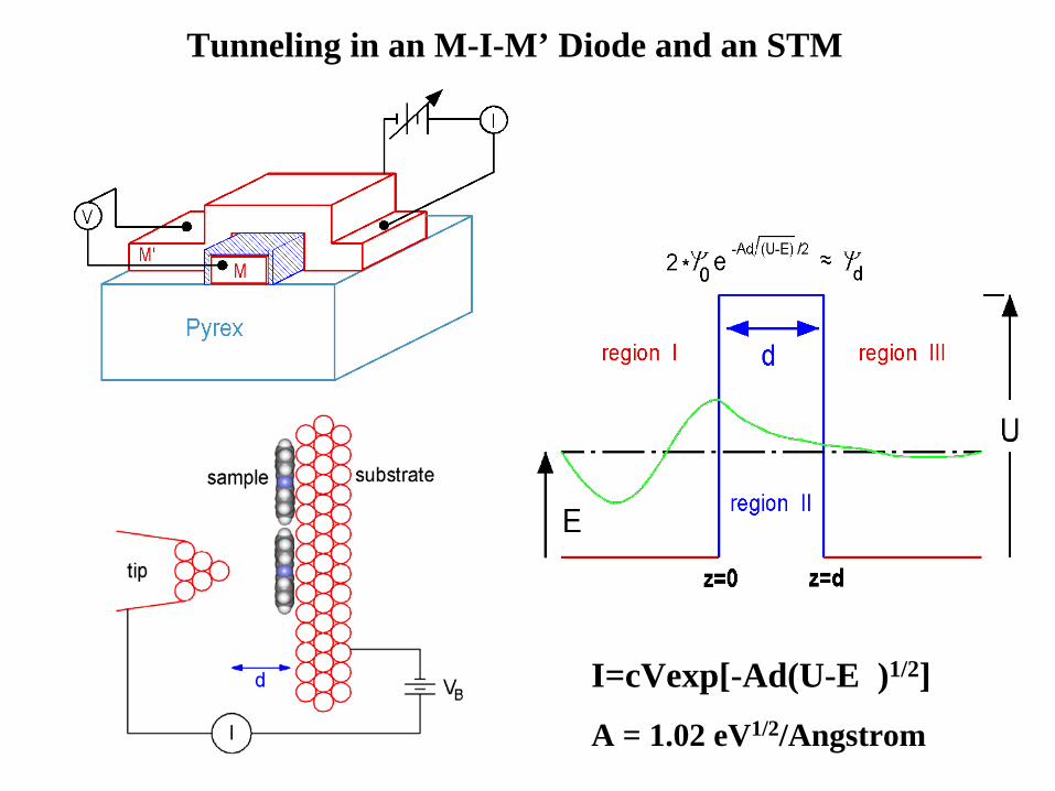
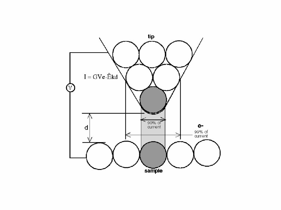
Tunneling in an M-I-M’ Diode and an STM
I=cVexp[-Ad(U-E )1/2]
A = 1.02 eV1/2/Angstrom

I
I CV exp(-d )~
Curre
nt (I
)
d
Voltage (V)
d > 5.0 nm1 2-1-2d = 1.0 nm
d = 0.9 nm
d = 0.8 nmD in Angstroms and
in eV


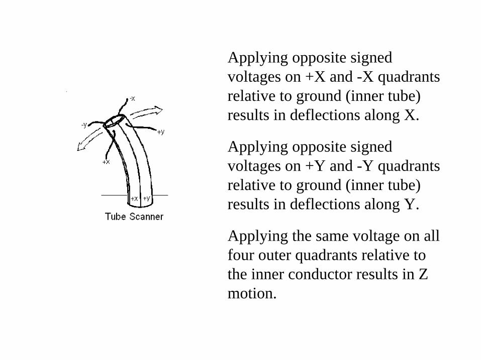
Applying opposite signed voltages on +X and -X quadrants relative to ground (inner tube) results in deflections along X.
Applying opposite signed voltages on +Y and -Y quadrants relative to ground (inner tube) results in deflections along Y.
Applying the same voltage on all four outer quadrants relative to the inner conductor results in Z motion.

z
x
CONSTANT CURRENT MODE
scan
I
Piez
o Mot
ion
(Feedback ON)
I C
V ex
p(-d
)
~
start
end
fast scan
slow
scan
step size
Raster Scan

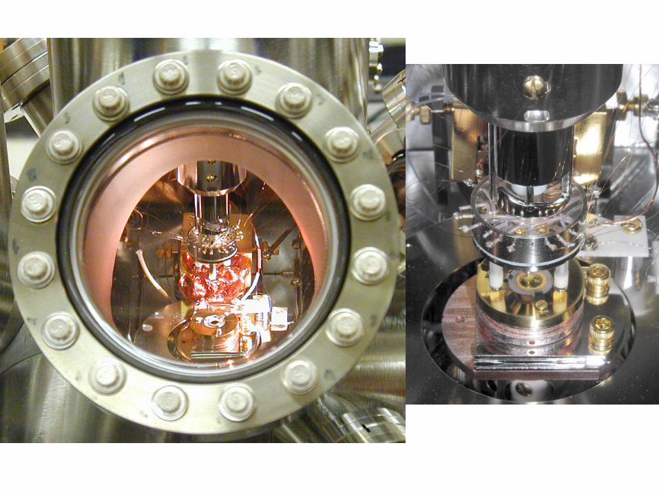

continuous flowLHe/LN UHV cryostat2
sample transfer armloadlock
STM chambersamplepreparationchamber
sample transfer arm
gatevalve
gatevalve
Top View of the variable temperature STM chamber
Side View
Sample Preparation
1. Gold is vapor deposited onto an atomically flat mica surface. The deposition rate is carefully controlled.
2. Single molecular samples are vapor deposited in the STM chamber onto the Au(111) surface. Typically, less than one monolayer is deposited
mica gold Sample
Sample evaporation
sourceAu
Resistively heated
Mica
Au vapor
Heated CuP < 2x 10 T-9
UHV Chamber
block
W boat

au-mica.086
Au(111) : Vapor Deposited on Mica

0 153 nm
0 2 nm
Reconstruction of the Au(111) surface
Height Image Derivative Image800 mV, 280 pA, 294 K

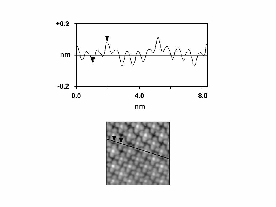
Atomic Resolution on Au(111)/Mica
0
0.14 nm
0 7.0 nm
25 mV, 2 nA, 294 K
[101]
[121]

Organometallics• Why do we care?
Intensely colored (Dyes, photochemistry, non-linear optics)
Extraordinary thermal and chemical stability(Deposited like inorganics, resist atmospheric attack and aging)
Ubiquitous in biology(Understanding porphyrin-like structures is highly desirable)
Exciting electronic properties(Both p-type and n-type semiconductors: OLEDs, Transistors, Sensors)
How do we do it?Conventional spectroscopy, a few hundred billion at a time.
(XPS, UPS, UV-Vis, FT-IR, Raman, electrochemistry)Tunneling spectroscopy and microscopy, one molecule at a time.
(Orbital mediated tunneling spectroscopy)(Scanning tunneling microscopy)
Make them by thermal deposition, self-assembly, LB methods

Top and Side Views of a Metal Phthalocyanine (MPc)
1.5 nm

Typical low coverage image of an organometallic on Au(111)
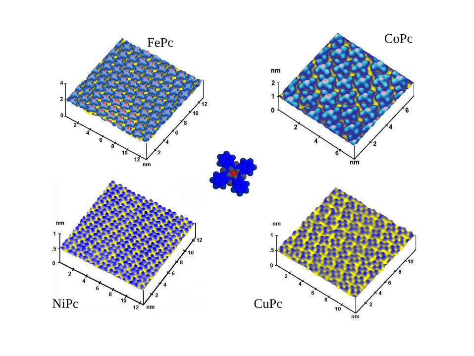
FePc CoPc
NiPc CuPc

Z
X
Au(111)
Tip
e-
The occupancy of metal d orbitals defines the conductivity at the center of the molecule.

+ + + +
PE(x) = -e /(x-x )2
Spatial Picture
Potential EnergyPicture
PE = 0 ev
PE = -20 eV
atomic core valence electron
iSi
i ixx
exPE2
)(
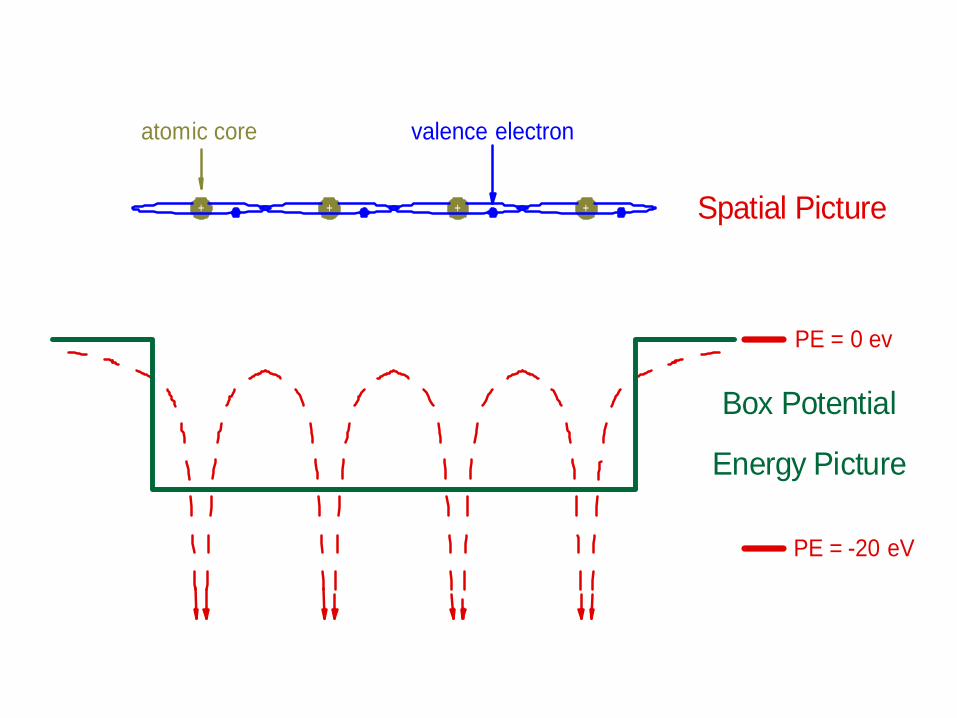
+ + + + Spatial Picture
Box Potential
Energy Picture
PE = 0 ev
PE = -20 eV
atomic core valence electron
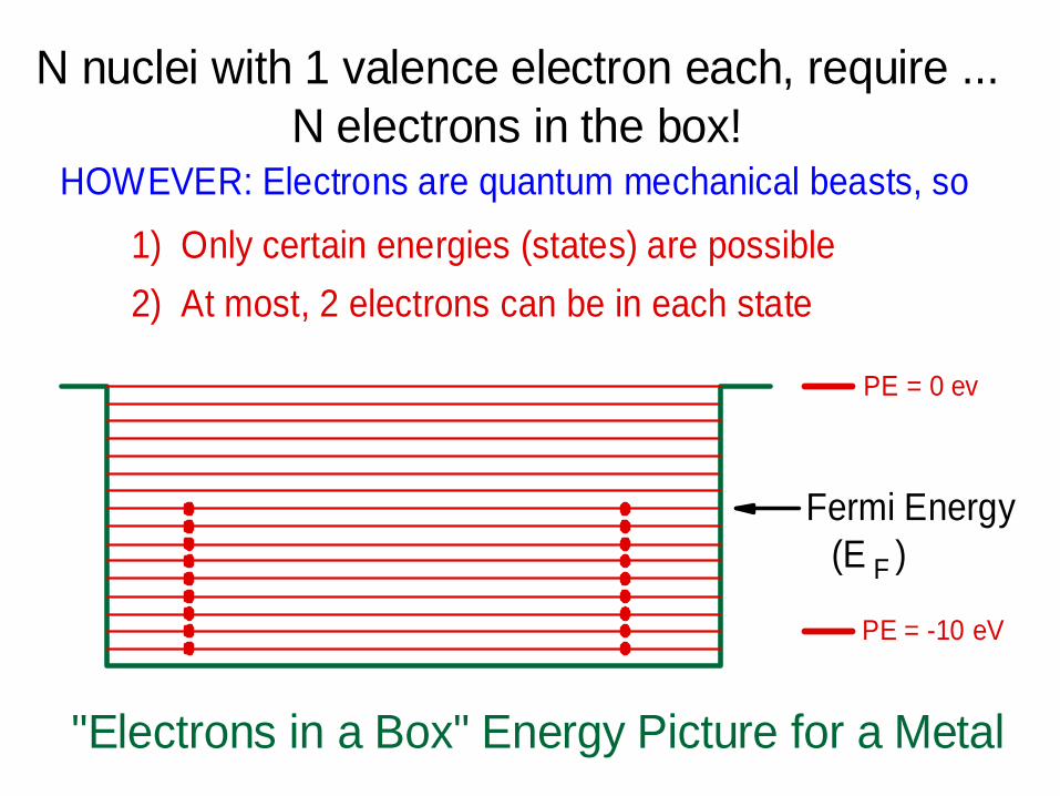
"Electrons in a Box" Energy Picture for a Metal
PE = 0 ev
PE = -10 eV
N electrons in the box!HOWEVER: Electrons are quantum mechanical beasts, so
1) Only certain energies (states) are possible2) At most, 2 electrons can be in each state
Fermi Energy(E )F
N nuclei with 1 valence electron each, require ...

E F
f
Potential barier to electron flowbetween metals
Metal MetalVacuum Gap
d
f
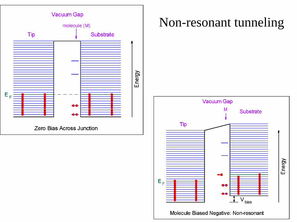
Non-resonant tunneling

T
S
TS
Metal Tip
Vacuum Space
Conducting Support
AdsorbateState Density
E
E
vacuum
Fermi
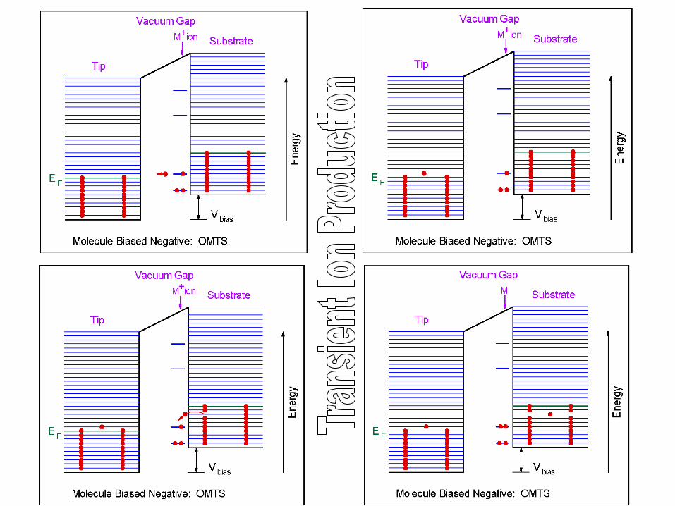
Negative Bias
Positive Bias
Vbias
Vbias
0.0-1.0-2.0 +1.0 +2.0Sample Bias (V)
dI/d
V
STM-OMTS at 298K
unoccupied orbital
5.26.27.2 4.2 3.2Energy Below Vacuum Level (eV)
occupied orbital(transient oxidation)
(transient reduction)
EF
ro
r
o
cobalt(II) tetraphenylporphyrin
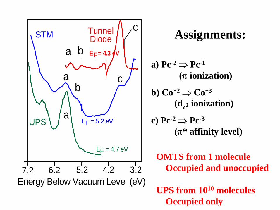
Energy Below Vacuum Level (eV)7.2 6.2 5.2 4.2 3.2
STM
UPS
TunnelDiode
E = 4.7 eVF
E = 5.2 eVF
E = 4.3 eVFa
a
a
b
b
c
c
Assignments:
a) Pc-2 Pc-1
(
ionization)
b) Co+2 Co+3
(dz2 ionization)
c) Pc-2 Pc-3
(* affinity level)
OMTS from 1 moleculeOccupied and unoccupied
UPS from 1010 moleculesOccupied only
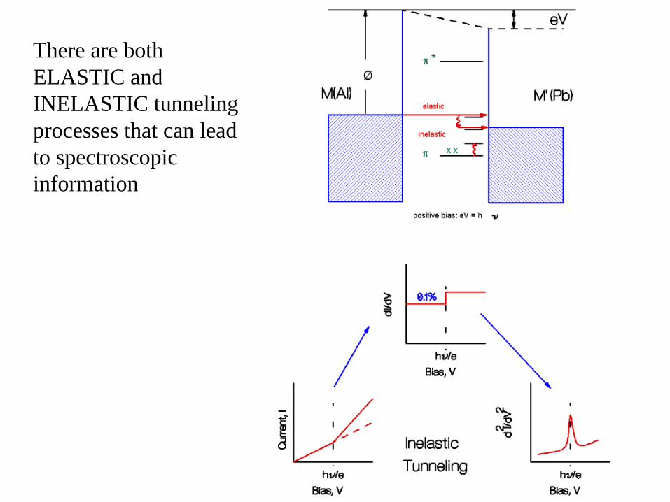
There are both ELASTIC and INELASTIC tunneling processes that can lead to spectroscopic information
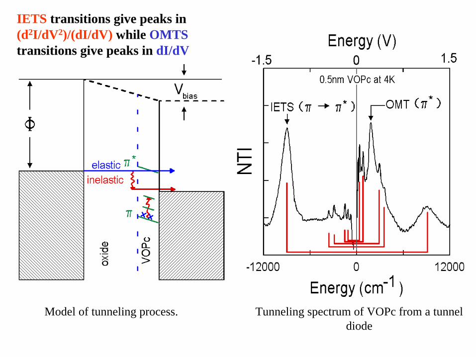
Model of tunneling process. Tunneling spectrum of VOPc from a tunnel diode
IETS transitions give peaks in (d2I/dV2)/(dI/dV) while OMTS transitions give peaks in dI/dV

Comparison of a low resolution vibrational IETS spectrum taken in a tunnel diode at 4K with conventional IR and Raman spectra.
You can easily resolve bands that are 50 cm-1 (6 meV) apart, such as the pair near 600 cm-1.
K. W. Hipps and A. T. Aplin, J. Phys. Chem., 89, 5459-5464 (1985)