Embed Size (px)
Citation preview

32
Mold.Plus-800High Accuracy Vertical Machining Center
Travel (X/Y/Z)
: 800/550/500 mm (31.49/21.65/19.68 in.)
Table Size
: 1,150 x 510 mm (45.27 x 20.07 in.)
Max. Loading Capacity
: 500 kg (1,100 lb.)
*Actual results are not guaranteed values.
Mold.Plus New High Accuracy Vertical
Incorporating box slideways, a high
accuracy scale feedback system on allaxes, a 20,000min-1 Matsuura Hi-Tech
Spindle offering effortless power,Matsuura's renowned Thermal Growth
Compensation System & sustained posi-tioning accuracy of 1 micron, Matsuura's
Mold.Plus-800 is the machine for allmodern Mold & Die manufacturers.
Mold.Plus
Circularity 1 µm *Actual Result
Filter : 1-15Material : Aluminum A5052Spindle Speed : 5,000 min-1
Feedrate : 1,000 mm/minTool : Endmill 2 tooth
Filter : 1-150Material : Aluminum A5052Spindle Speed : 5,000 min-1
Feedrate : 1,000 mm/minTool : Endmill 2 tooth
Circularity 2 µm *Actual Result
Phenomenal High Accuracy Cutting
Effortless Power,Superior Accuracy
2 µm/div 2 µm/div

54
Positioning Accuracywithin 1 µm on all axes
*Actual Result
Thermal DisplacementCompensation Function
Thermal Displacement Valuewithin 5 µm during continuous6 hours, 20,000 min-1 running
*Actual Result
Thermal Displacement Value on All Axes duringcontinuous 6 hours running
*Actual results are not guaranteed values.
Taper : BT40 ( Double Face Contact )
Speed : 20,000 min-1
Motor Power : 15/18.5kW (25HP)
Max. Torque : 108.5 Nm/1,320 min-1
High Speed 20,000 min-1 High Accuracy
Matsuura Hi-Tech SpindleHigh ResolutionLinear Scales
• Due to the high accuracy, 0.05 µm resolu-tion linear scales excellent repeatability,
positioning & superb machining results areachieved - every time. • By utilizing the spindle thermal displacement
compensation function, the sustained accuracy
of this outstanding machine is assured overmany years of operation.
Error
Position
Positioning Accuracy on All Axes
Displacement Value
• Utilizing Matsuura's many decades of pioneering highspeed machining experience, our spindles are designed &
assembled ‘in house’. Matsuura's spindle engineers workin a dedicated clean room complex to assure the highest
quality & reliability, the precision spindles are assembledto guarantee a runout of less than 1 µm (0.000039 in.)
(actually measured value) at the nose of the spindle.
• The spindle and the motor are connected by Matsuura's
unique coupling. This assembly is designed to preventthe heat from being transferred from the motor to the
spindle & contributes to the high rigidity of the spindle.
• To minimize heat buildup in the spindle, cooled oil is
circulated around the outer jacket of the spindle andmotor as well as the motor flange, thus sustaining its
high accuracy.
• The standard, double contact of the face & taper, unifica-
tion of the spindle & drive key features a unique toolclamp mechanism to improve repeatability and station-
ary/dynamic rigidity. This results in excellent materialremoval rates and surface finish.
• Widely spaced, rectangular guideways on all axes
are finished by traditional hand scraping to
minimise wear & offer life long accuracy.
• Significant ribbing of the bed & column -
designed & optimized by FEM analysis.
POWER (kW)
SPINDLE SPEED (min-1)
(Figure of System)
TORQUE (Nm)
76
*Handy Man provides major savings by reducing set-
up, programming, operating & maintenance times.
Please contact Matsuura for a copy of our in-depth
Handy Man brochure.
Proven Software Performance
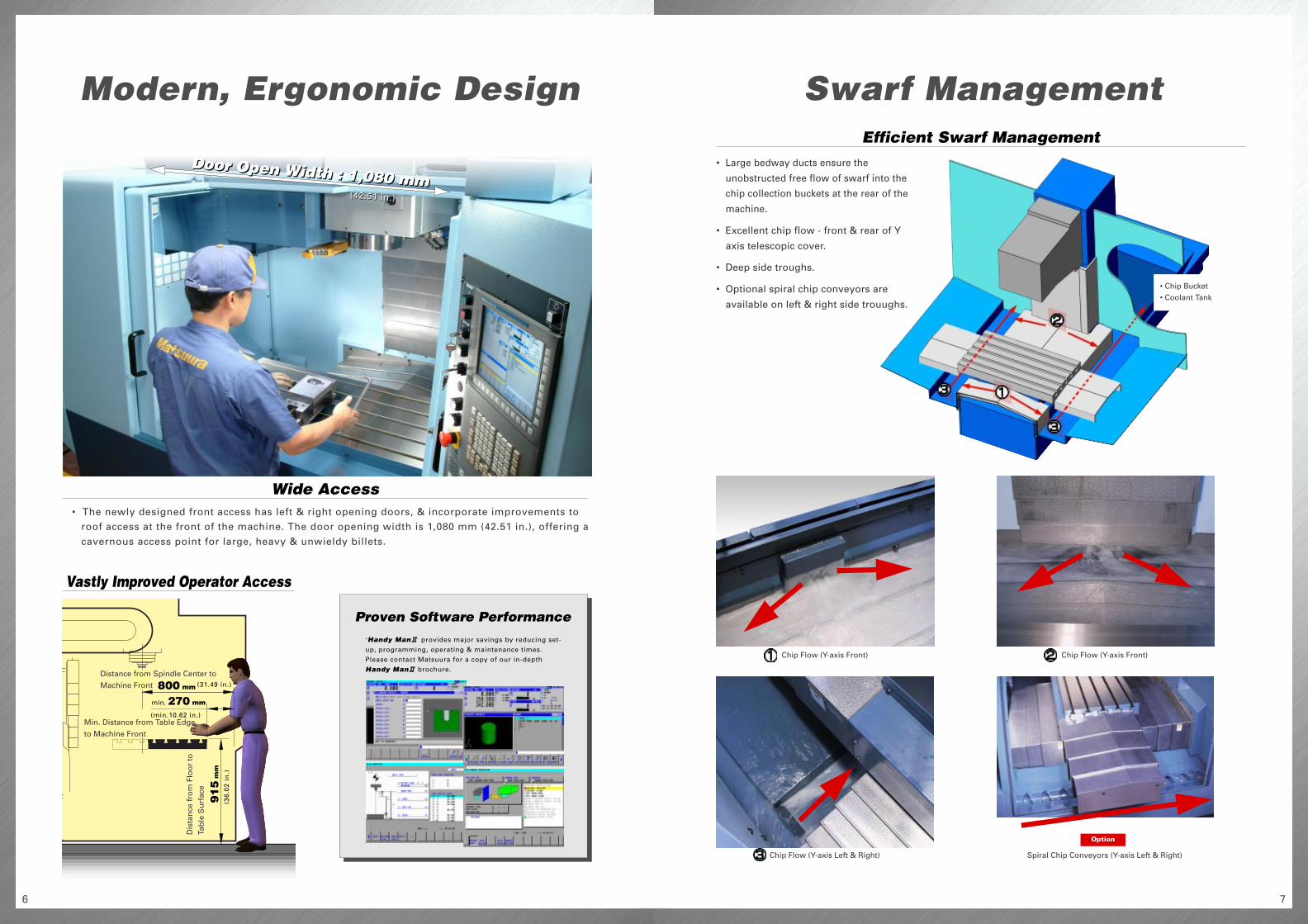
Swarf ManagementModern, Ergonomic Design
• The newly designed front access has left & right opening doors, & incorporate improvements toroof access at the front of the machine. The door opening width is 1,080 mm (42.51 in.), offering a
cavernous access point for large, heavy & unwieldy billets.
Vastly Improved Operator Access
Wide Access
• Large bedway ducts ensure the
unobstructed free flow of swarf into the
chip collection buckets at the rear of the
machine.
• Excellent chip flow - front & rear of Y
axis telescopic cover.
• Deep side troughs.
• Optional spiral chip conveyors are
available on left & right side trouughs.
Efficient Swarf Management
Door Open Width : 1,080 mmDoor Open Width : 1,080 mm
(31.49 in.)
(min.10.62 in.)
(36
.02
in
.)
(42.51 in.)(42.51 in.)
800 mm
min. 270 mm
91
5 m
m
Distance from Spindle Center to
Machine Front
Min. Distance from Table Edge
to Machine Front
Dis
tan
ce f
rom
Flo
or
toTa
ble
Su
rfac
e
Chip Flow (Y-axis Front)
Chip Flow (Y-axis Left & Right) Spiral Chip Conveyors (Y-axis Left & Right)
Option
Chip Flow (Y-axis Front)
• Chip Bucket• Coolant Tank

98
*max.1,000 block available as option.
IZ-2/150NF
Nano Smoothing (X/Y/Z)
Look-ahead Block Expansion up to 1,000 pcs
Fast Data Server (100/10 Base-T compatible)
Optimal Torque Ace./Dec.
Powerful, High Performance
IPC
AD-TAP
High Speed & High Precision PackageOption
Mold.Plus-800 Table Surface
Mold.Plus-800 Outline
IZ-1/15FIZ-1/30NF, IZ-2/150NF
( Look Ahead Linear Ace./dec. + nano interpolation )
Matsuura G-Tech 30i Mold.Plus-800 Floor Plan
Example
• Executing the max. 200(IZ-1/30NF)- or
600*(IZ-2/150NF)-block look ahead linear
acc./dec. before interpolation achieves a
smooth acc./dec. across the multiple blocks
calculated by nano order.
• For high speed cutting applications, Matsuura's
proven and pioneering software is recommended.When utilizing this software, setting the required
part accuracy level is quick, simple and user friendly,allowing you to prioritize precision against speed.
• Matsuura's unique
spindle motor control
technology- AD-TAP,
intelligently optimizes
the torque V speed
characteristics of the
spindle motor,
depending on the size
of the tap used. This
provides average
reduction of 20% in
tapping time.
(Patent Pending)
( Example number of tapped holesat same time )
8TappedHoles
10TappedHoles
AD-TAPPreviousTapping
Option
• Matsuura's original high speed control func-tion that compensates for any geometric error
between the machining program and theactual machined profile.
(10”
)
(3.9”)
(3.9”)
(3.9”) (10”
)
(20”
)
(3.9”)
(45.2”)
(11/16”)
For more Complex, Precision PartsFor General Parts or Mold & Die
Workpiece : Mold & DieNumber of Tools : 8
Materials : CENA1 (HRC40)Cycle Time : 16 hours
T-Slot Details
Number of Tools• 80 tools
Coolant /Swarf Management• Coolant Thru(2MPa/5MPa*/7MPa*)
:*with Coolant Temperature Controller
• External Nozzle (2MPa/5MPa)
• Coolant Temperature Controller (100L/200L)
• Chip Flush System
• Spiral Chip Conveyor (Right & Left)
• Lift-Up Chip Conveyor
( Hinge Type, Drum filter + Spiral Chip Conveyor )
• Chip Bucket
• Air Blow for Chip Swarf Removal
• Workpiece Cleaning Gun
Operation / Maintenance
Safety Features
• 8 Sets of Extra M Function
• Weekly Timer
• 3 Color Status Light (red, green, yellow)
• Spindle Run Hour Meter
• Automatic Operation Run Hour Display unit
• Movable Manual Pulse Generator
• Mist Separator Unit
• Rotary Wiper (Air Supply System)
• Coolant Flow Checker
• Door Interlock for Total Splash Guard
Tool Management /Workpiece Measurement• Touch Type In-Process TLM Measurement
+ Broken Tool Detection + Auto Centering
• In-Process Measurement & Broken Tool Laser Detection
• Touch probe
Others• Additional Axis (4/5th Table)
Options
1110
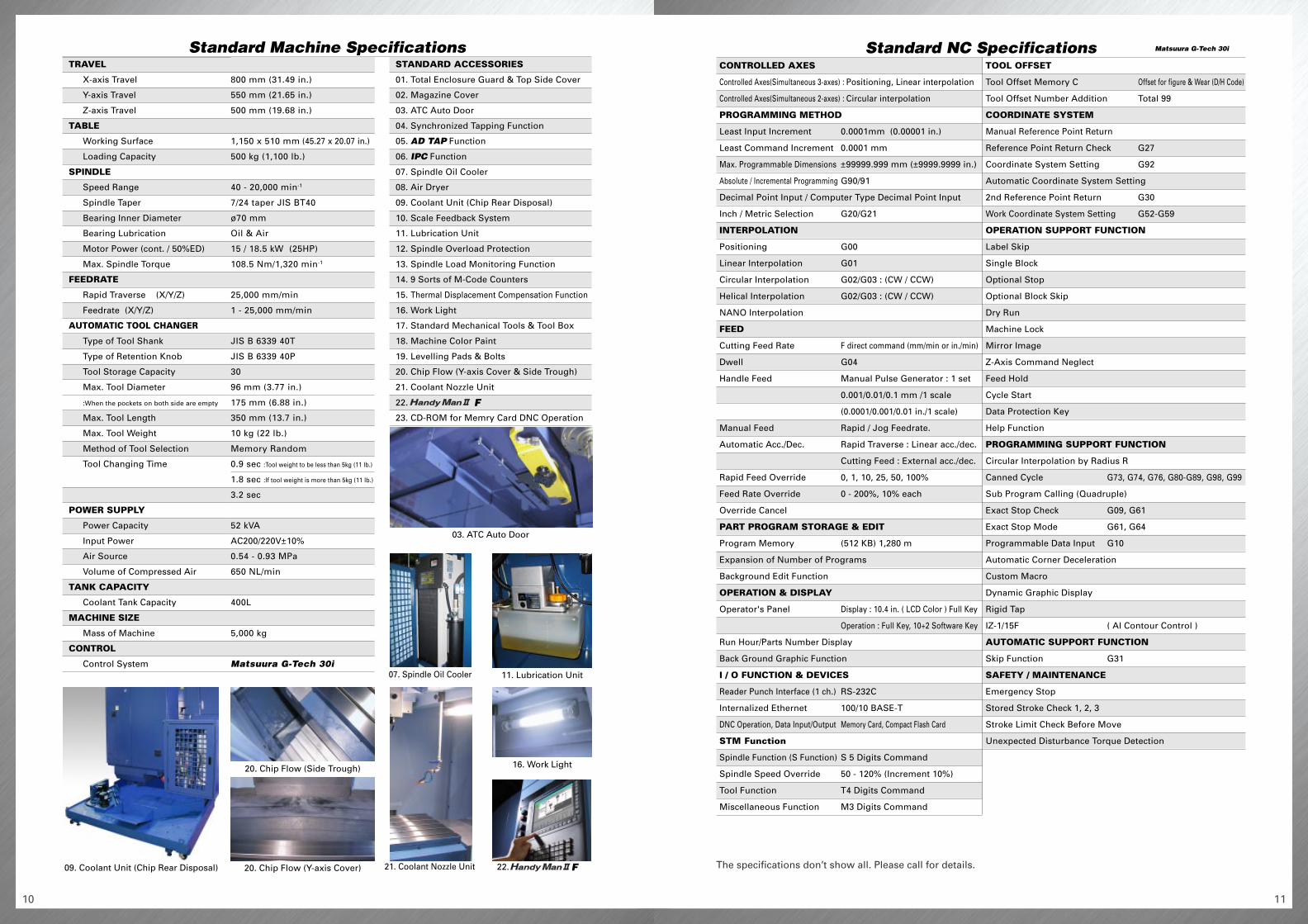
Standard Machine Specifications
800 mm (31.49 in.)
550 mm (21.65 in.)
500 mm (19.68 in.)
1,150 x 510 mm (45.27 x 20.07 in.)
500 kg (1,100 lb.)
40 - 20,000 min-1
7/24 taper JIS BT40
ø70 mm
Oil & Air
15 / 18.5 kW (25HP)
108.5 Nm/1,320 min-1
25,000 mm/min
1 - 25,000 mm/min
JIS B 6339 40T
JIS B 6339 40P
30
96 mm (3.77 in.)
175 mm (6.88 in.)
350 mm (13.7 in.)
10 kg (22 lb.)
Memory Random
0.9 sec :Tool weight to be less than 5kg (11 lb.)
1.8 sec :If tool weight is more than 5kg (11 lb.)
3.2 sec
52 kVA
AC200/220V±10%
0.54 - 0.93 MPa
650 NL/min
400L
5,000 kg
Matsuura G-Tech 30i
The specifications don’t show all. Please call for details.
Standard NC Specifications Matsuura G-Tech 30i
CONTROLLED AXES
Controlled Axes(Simultaneous 3-axes) : Positioning, Linear interpolation
Controlled Axes(Simultaneous 2-axes) : Circular interpolation
PROGRAMMING METHOD
Least Input Increment 0.0001mm (0.00001 in.)
Least Command Increment 0.0001 mm
Max. Programmable Dimensions ±99999.999 mm (±9999.9999 in.)
Absolute / Incremental Programming G90/91
Decimal Point Input / Computer Type Decimal Point Input
Inch / Metric Selection G20/G21
INTERPOLATION
Positioning G00
Linear Interpolation G01
Circular Interpolation G02/G03 : (CW / CCW)
Helical Interpolation G02/G03 : (CW / CCW)
NANO Interpolation
FEED
Cutting Feed Rate F direct command (mm/min or in./min)
Dwell G04
Handle Feed Manual Pulse Generator : 1 set
0.001/0.01/0.1 mm /1 scale
(0.0001/0.001/0.01 in./1 scale)
Manual Feed Rapid / Jog Feedrate.
Automatic Acc./Dec. Rapid Traverse : Linear acc./dec.
Cutting Feed : External acc./dec.
Rapid Feed Override 0, 1, 10, 25, 50, 100%
Feed Rate Override 0 - 200%, 10% each
Override Cancel
PART PROGRAM STORAGE & EDIT
Program Memory (512 KB) 1,280 m
Expansion of Number of Programs
Background Edit Function
OPERATION & DISPLAY
Operator's Panel Display : 10.4 in. ( LCD Color ) Full Key
Operation : Full Key, 10+2 Software Key
Run Hour/Parts Number Display
Back Ground Graphic Function
I / O FUNCTION & DEVICES
Reader Punch Interface (1 ch.) RS-232C
Internalized Ethernet 100/10 BASE-T
DNC Operation, Data Input/Output Memory Card, Compact Flash Card
STM Function
Spindle Function (S Function) S 5 Digits Command
Spindle Speed Override 50 - 120% (Increment 10%)
Tool Function T4 Digits Command
Miscellaneous Function M3 Digits Command
TOOL OFFSET
Tool Offset Memory C Offset for figure & Wear (D/H Code)
Tool Offset Number Addition Total 99
COORDINATE SYSTEM
Manual Reference Point Return
Reference Point Return Check G27
Coordinate System Setting G92
Automatic Coordinate System Setting
2nd Reference Point Return G30
Work Coordinate System Setting G52-G59
OPERATION SUPPORT FUNCTION
Label Skip
Single Block
Optional Stop
Optional Block Skip
Dry Run
Machine Lock
Mirror Image
Z-Axis Command Neglect
Feed Hold
Cycle Start
Data Protection Key
Help Function
PROGRAMMING SUPPORT FUNCTION
Circular Interpolation by Radius R
Canned Cycle G73, G74, G76, G80-G89, G98, G99
Sub Program Calling (Quadruple)
Exact Stop Check G09, G61
Exact Stop Mode G61, G64
Programmable Data Input G10
Automatic Corner Deceleration
Custom Macro
Dynamic Graphic Display
Rigid Tap
IZ-1/15F ( AI Contour Control )
AUTOMATIC SUPPORT FUNCTION
Skip Function G31
SAFETY / MAINTENANCE
Emergency Stop
Stored Stroke Check 1, 2, 3
Stroke Limit Check Before Move
Unexpected Disturbance Torque Detection
F
F
03. ATC Auto Door
07. Spindle Oil Cooler 11. Lubrication Unit
16. Work Light
21. Coolant Nozzle Unit 22.
20. Chip Flow (Side Trough)
09. Coolant Unit (Chip Rear Disposal) 20. Chip Flow (Y-axis Cover)
TRAVEL
X-axis Travel
Y-axis Travel
Z-axis Travel
TABLE
Working Surface
Loading Capacity
SPINDLE
Speed Range
Spindle Taper
Bearing Inner Diameter
Bearing Lubrication
Motor Power (cont. / 50%ED)
Max. Spindle Torque
FEEDRATE
Rapid Traverse (X/Y/Z)
Feedrate (X/Y/Z)
AUTOMATIC TOOL CHANGER
Type of Tool Shank
Type of Retention Knob
Tool Storage Capacity
Max. Tool Diameter
:When the pockets on both side are empty
Max. Tool Length
Max. Tool Weight
Method of Tool Selection
Tool Changing Time
POWER SUPPLY
Power Capacity
Input Power
Air Source
Volume of Compressed Air
TANK CAPACITY
Coolant Tank Capacity
MACHINE SIZE
Mass of Machine
CONTROL
Control System
STANDARD ACCESSORIES
01. Total Enclosure Guard & Top Side Cover
02. Magazine Cover
03. ATC Auto Door
04. Synchronized Tapping Function
05. AD TAP Function
06. IPC Function
07. Spindle Oil Cooler
08. Air Dryer
09. Coolant Unit (Chip Rear Disposal)
10. Scale Feedback System
11. Lubrication Unit
12. Spindle Overload Protection
13. Spindle Load Monitoring Function
14. 9 Sorts of M-Code Counters
15. Thermal Displacement Compensation Function
16. Work Light
17. Standard Mechanical Tools & Tool Box
18. Machine Color Paint
19. Levelling Pads & Bolts
20. Chip Flow (Y-axis Cover & Side Trough)
21. Coolant Nozzle Unit
22.
23. CD-ROM for Memry Card DNC Operation

Superior Accuracy Vertical Machining Center
Mold.Plus-800
EY-E1.0 200503 3000 S
• Product specifications and dimensions are subject to change without prior notice.
• The photos may show optional accessories.
• Products are subject to all applicable export control laws and regulations.
Website : www.matsuura.co.jpe-mail : [email protected]
Printed on recycled paper.
MATSUURA MACHINERY CORPORATION1-1 Urushihara-cho Fukui City 910-8530, Japan<Tel> +81-776-56-8106 <Fax> +81-776-56-8151
MATSUURA EUROPE GmbHOtto-Von-Guericke-Ring 10a 65205 Wiesbaden-Nordenstadt, Germany<Tel> +49-6122-7803-80 <Fax> +49-6122-7803-33<e-mail> [email protected]<web-site> www.matsuura.de
MATSUURA MACHINERY PLCBeaumont Centre Whitwick Business Park, CoalvilleLeicestershire LE67 4NH England<Tel> +44-1530-511-400 <Fax> +44-1530-511-440<e-mail> [email protected]<web-site> www.matsuura.co.uk
MATSUURA MACHINERY GmbHOtto-Von-Guericke-Ring 10a 65205 Wiesbaden-Nordenstadt, Germany<Tel> +49-6122-7803-0 <Fax> +49-6122-7803-33<e-mail> [email protected]<web-site> www.matsuura.de
ELLIOTT MATSUURA CANADA INC.2120 Buckingham Road Oakville Ontario L6H 5X2, Canada<Tel> +1-905-829-2211 <Fax> +1-905-829-5600<e-mail> [email protected]<web-site> www.elliottmachinery.com
MMTS CORPORATION65 Union Avenue Suite2, Sudbury Massachusetts 01776, U.S.A.<Tel> +1-978-443-5388 <Fax> +1-978-443-9524