Embed Size (px)
Citation preview
A mold-making procedure for multiple orbital prostheses fabrication
Trakol Mekayarajjananonth, DDS, MS,a Thomas J. Salinas, DDS,b
Mark S. Chambers, DMD, MS,c and James C. Lemon, DDSd
Faculty of Dentistry, Chulalongkorn University, Bangkok, Thailand; University of NebraskaCollege of Medicine, Omaha, Neb.; and The University of Texas M.D. Anderson Cancer Center,Houston, Texas
Traditional methods of fabricating orbital prostheses rely on the “lost wax” technique to produce arealistic representation of the sculpted pattern produced in the defect. The usual constituents of themold that reproduces the subtleties of the palpebral fissure are often minute, making them prone tofracture and subsequent dissolution by repeated attempts at pressing each prosthesis. The followingmethod provides a mold resistant to these problems with light-polymerized resin surrounding the pal-pebral part of the orbital mold. (J Prosthet Dent 2003;90:97-100.)
Many variations exist in techniques and materialsfor fabricating orbital prostheses.1-18 One of the criticalsteps in fabrication is the production of a mold from acustom-sculpted orbital pattern. This step requires greatattention to detail to produce an accurate reproductionof the sculpted pattern. Wolfaardt et al13 described atechnique that provided a mold acceptable for fabricat-ing duplicate prostheses. The technique creates space forthe ocular portion in the wax/clay pattern by removingthe ocular prosthesis and pouring an improved stoneinto the void in the upper half of the mold. Joose et al14
separated the master cast side of the mold into 4 sec-tions, which allowed trial closure for fabrication of mul-tiple prostheses. Levy et al15 fabricated a 3-piece layeredflexible moulage made from autopolymerizing acrylicresin, room temperature vulcanizing silicone rubber,and a backing layer of dental stone. Two slices were cutin the acrylic resin section to allow the section to flex.Chambers et al17 demonstrated the use of a custom flaskmade of polyvinyl chloride pipe with critical parts of themold made of autopolymerizing acrylic resin for fabri-cating an auricular prosthesis. A study by Jebreil16 re-ported that most patients needed their orbital prosthesesrenewed every 6 to 9 months. The reasons given by thepatients were change in color, marginal breakdown ofthe prosthesis, change in the defect, and surgical recon-struction of the defect. For the first 2 reasons, use ofadhesives, routine cleaning, ultraviolet light, and air pol-lution all contributed in some way to degradation ofcolor and marginal integrity.16,18 These frequent pros-
theses remakes require a mold that is durable to thestresses placed on the internal surfaces by acid dissolu-tion and elastic pull when recovering the prosthesis.Common materials for mold fabrication are acrylic resin,epoxy resin, silicone, Lipowitz metal, dental stone, or acombination of these materials. Among these, dentalstone is the most commonly used.17 Stone molds arerelatively easy to construct, accurate, and inexpensive;however, the stone is fragile in the palpebral area andsusceptible to fracture during the processing.12 Whenthe orbital prosthesis is fabricated from a stone moldwhere this breakage may have occurred, the details ofthis area are lost, creating difficulty in capturing theesthetic camouflage. The technique presented here of-fers an improvement that provides a mold acceptable forfabricating multiple orbital prostheses by use of light-polymerizing material (Triad gel; Dentsply Caulk, York,Pa) surrounding the palpebral part of the orbital mold,which is commonly made of improved stone.
PROCEDURE
1. Make an impression of the orbital defect and fabri-cate a master cast with improved dental stone (DieKeen green; Modern Materials, Heraeus Kulzer,Armonk, NY).
2. Prepare vertical and horizontal grooves into theposterior surface of the ocular prosthesis for keyingit to a pedestal base after wax/clay elimination.
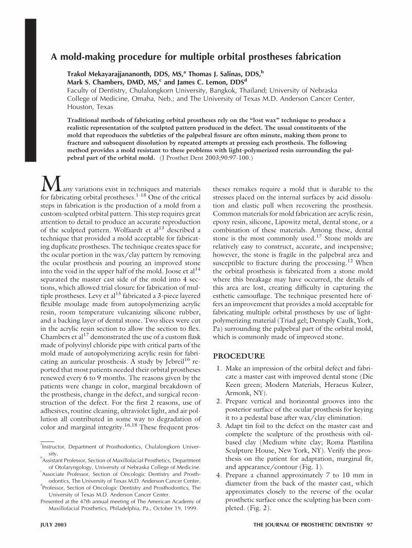
3. Adapt tin foil to the defect on the master cast andcomplete the sculpture of the prosthesis with oil-based clay (Medium white clay; Roma PlastilinaSculpture House, New York, NY). Verify the pros-thesis on the patient for adaptation, marginal fit,and appearance/contour (Fig. 1).
4. Prepare a channel approximately 7 to 10 mm indiameter from the back of the master cast, whichapproximates closely to the reverse of the ocularprosthetic surface once the sculpting has been com-pleted. (Fig. 2).
aInstructor, Department of Prosthodontics, Chulalongkorn Univer-
sity.bAssistant Professor, Section of Maxillofacial Prosthetics, Department
of Otolaryngology, University of Nebraska College of Medicine.cAssociate Professor, Section of Oncologic Dentistry and Prosth-
odontics, The University of Texas M.D. Anderson Cancer Center.dProfessor, Section of Oncologic Dentistry and Prosthodontics, The
University of Texas M.D. Anderson Cancer Center.Presented at the 47th annual meeting of The American Academy of
Maxillofacial Prosthetics, Philadelphia, Pa., October 19, 1999.
JULY 2003 THE JOURNAL OF PROSTHETIC DENTISTRY 97
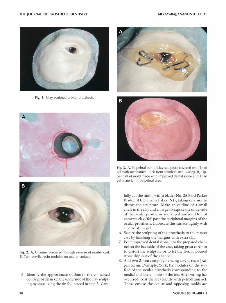
5. Identify the approximate outline of the containedocular prosthesis on the underside of the clay sculpt-ing by visualizing the tin foil placed in step 3. Care-
fully cut the tinfoil with a blade (No. 25 Bard ParkerBlade; BD, Franklin Lakes, NJ), taking care not todistort the sculpture. Make an outline of a smallcircle in the clay and enlarge to expose the undersideof the ocular prosthesis and keyed surface. Do notexcavate clay/foil past the peripheral margins of theocular prosthesis. Lubricate this surface lightly witha petrolatum gel.
6. Secure the sculpting of the prosthesis to the mastercast by finishing the margins with extra clay.
7. Pour improved dental stone into the prepared chan-nel on the backside of the cast, taking great care notto distort the sculpture or to let the freshly pouredstone drip out of the channel.
8. Add two 3-mm autopolymerizing acrylic resin (Re-pair Resin; Dentsply, York, Pa) nodules on the sur-face of the ocular prosthesis corresponding to themedial and lateral limits of the iris. After setting hasoccurred, coat the area lightly with petrolatum gel.These ensure the ocular and opposing molds are
Fig. 1. Clay sculpted orbital prosthesis.
Fig. 2. A, Channel prepared through reverse of master cast.B, Two acrylic resin nodules on ocular surface.
Fig. 3. A, Palpebral part of clay sculpture covered with Triadgel with mechanical lock from stainless steel wiring. B, Up-per half of mold made with improved dental stone and Triadgel material in palpebral area.
THE JOURNAL OF PROSTHETIC DENTISTRY MEKAYARAJJANANONTH ET AL
98 VOLUME 90 NUMBER 1

correctly aligned when silicone is placed into themold (Fig. 3).
9. Apply clear, unfilled light-polymerizing resin gel(Triad gel; Dentsply Caulk) to cover the ocular anddelicate fissuring on both sides of the canthus. Be-fore light polymerizing, add stainless steel bent wir-ing (.036� round wire; Great Lakes Orthodontics,Tonawanda, NY) into the gel projecting irregularly1 to 2 cm out of the light-polymerizing resin gel toprovide a mechanical lock from the gel to the dentalstone (Fig. 4).
10. Coat the exposed stone surfaces of intaglio surfaceof the cast with a petrolatum gel before pouring theopposing part of the mold with improved dentalstone (Fig. 5).
11. After the upper half of the mold has set, separate thehalves and eliminate the clay sculpting material bygross removal and a mild detergent scrub.
12. Thoroughly clean the ocular prosthesis with a milddetergent and water. Insert and invest in a splitgypsum mold to duplicate it in autopolymerizing
acrylic resin. This will serve as a blank for producingduplicate silicone prostheses without the need forthe patient’s present prosthesis (Fig. 6, A).
Fig. 4. A, Ocular prosthetic pedestal in lower half of mold.B, Ocular prosthesis keyed and placed on pedestal.
Fig. 5. Raw silicone orbital prosthesis.
Fig. 6. A, Ocular prosthesis duplicated in autopolymerizingacrylic resin. B, Extrinsic coloring of finished orbitalprosthesis.
MEKAYARAJJANANONTH ET AL THE JOURNAL OF PROSTHETIC DENTISTRY
JULY 2003 99

13. After both halves of the mold have been preparedfor packing, place the ocular prosthesis nodule sidedown onto the resin gel part of the opposing moldhalf (Fig. 4). Make sure the tissue half of the moldcloses correctly and completely.
14. After silicone packing and vulcanization, recoverthe prosthesis from the mold and trim all excess atthe margins and palpebral fissure (Fig. 5). Clean theprosthesis surface gently with acetone to removeany surface contaminants placed by skin oils ormold separating media. Extrinsically tint the pros-thesis in the usual manner12 (Fig. 6, B).
SUMMARY
This article describes an improved mold-making pro-cedure that can be used for fabricating multiple orbitalprostheses. It provides a resistant portion that incorpo-rates light-polymerized resin to preserve the details ofthe intercanthal region.
REFERENCES1. Bulbulian AH. Facial prosthetics. Springfield (IL): Charles C Thomas Pub-
lishing; 1973. p. 349-63.2. Roberts AC. Facial prostheses: the restoration of facial defects by pros-
thetic means. London: Henry Kimpton; 1971. p. 52-8.3. Oral K, Zini I, Aramany MA. Construction of orbital prostheses using the
silicone pattern technique. J Prosthet Dent 1978;40:430-3.4. Joneja OP, Madan SK, Mehra MD, Dogra RN. Orbital prostheses. J Pros-
thet Dent 1976;36:306-11.5. Gandhi NK, Bhatt NA. Obturator-orbital prosthesis. J Prosthet Dent 1980;
44:336-7.6. Antoniou DV, Toljanic JA, Graham L. Obturator prosthesis retention for
edentulous patients with large palatal defects: a clinical report. J ProsthetDent 1996;76:227-9.
7. Barron JB, Rubenstein JE, Archibald D, Manor RE. Two-piece orbitalprosthesis. J Prosthet Dent 1983;49:386-8.
8. Shifman A. Simplified fabrication of orbital prostheses using posteriorattachment for the artificial eye. J Prosthet Dent 1993;69:73-6.
9. Polyzios GL. Using an existing orbital prosthesis in the construction of anew one. J Prosthodont 1995;4:265-8.
10. Brown KE. Fabrication of orbital prosthesis. J Prosthet Dent 1969;22:592-607.
11. McKinstry RE. Fundamentals of facial prosthetics. Arlington (VA): ABIProfessional Publications; 1995. p. 121-36.
12. Beumer J, Curtis TA, Marunick MT. Maxillofacial rehabilitation: prosth-odonrtic and surgical considerations. St. Louis: Ishiyaku EuroAmerica;1996. p. 377-53.
13. Wolfaardt JF, Hacqueboard A, Els JM. A mold technique for constructionof orbital prostheses. J Prosthet Dent 1983;50:224-6.
14. Jooste C, Bester D, Roets R. A mold technique for orbital prostheses. JProsthet Dent 1992;67:380-2.
15. Levy M, Schortz RH, Blumenfeld I, Lepley JB. A flexible moulage for thefabrication of an orbital prosthesis. J Prosthet Dent 1980;43:436-8.
16. Jebreil K. Acceptability of orbital prostheses. J Prosthet Dent 1980;43:82-5.
17. Chambers MS, Lemon JC, Martin JW, Wesley PJ. A hybrid-mold techniquefor fabricating facial prostheses. J Prosthet Dent 1996;75:53-5.
18. Lemon JC, Chambers MS, Jacobsen ML, Powers JM. Color stability of facialprostheses. J Prosthet Dent 1995;74:613-8.
Reprint requests to:DR TRAKOL MEKAYARAJJANANONTH
DEPARTMENT OF PROSTHODONTICS
FACULTY OF DENTISTRY
CHULALONGKORN UNIVERSITY
HENRI-DUNANT ROAD, BANGKOK 10330THAILANDFAX: (662) 676-0236, 218-8534E-MAIL: [email protected]
Copyright © 2003 by The Editorial Council of The Journal of ProstheticDentistry.
0022-3913/2003/$30.00 � 0
doi:10.1016/S0022-3913(03)00216-6
Receive Table of Contents by E-mail
To receive the table of contents by e-mail, sign up through our Web site at http://www.mosby.com/prosdent.Choose E-mail Notification.Simply type your e-mail address in the box and click the Subscribe button.Alternatively, you may send an e-mail message to [email protected]. Leave the subject line blank andtype the following as the body of your message:
subscribe prosdent_tocYou will receive an e-mail to confirm that you have been added to the mailing list.Note that table of contents e-mails will be sent out when a new issue is posted to the Web site.
THE JOURNAL OF PROSTHETIC DENTISTRY MEKAYARAJJANANONTH ET AL
100 VOLUME 90 NUMBER 1
![INDEX [microdentsystem.com] · 2015-11-24 · INDEX PRESENTATION. INTRODUCTION MULTIPLE PROSTHESIS. REMOVABLE AND IMMEDIATE PROSTHESIS. SINGLE PROSTHESIS CEMENTED PROSTHESIS. Microdent](https://img.dokumen.tips/doc/110x75/5facd9ee77a5ed547a36b19c/index-2015-11-24-index-presentation-introduction-multiple-prosthesis-removable.jpg)


![INDEX [microdentsystem.com] · INTRODUCTION REMOVABLE AND IMMEDIATE . PROSTHESIS MULTIPLE PROSTHESIS. CEMENTED PROSTHESIS. Microdent Genius conical (straight) abutment or Microdent](https://img.dokumen.tips/doc/110x75/5facd9ef77a5ed547a36b19e/index-introduction-removable-and-immediate-prosthesis-multiple-prosthesis.jpg)

![Intelligent Prosthesis - tams. · PDF fileI Electrooculography (EOG) I Electrocorticogram (EcoG) [ ] Irina Intelligent Prosthesis 4/21. ... Irina Intelligent Prosthesis 21/21](https://img.dokumen.tips/doc/110x75/5aab10c57f8b9aa9488b839d/intelligent-prosthesis-tams-electrooculography-eog-i-electrocorticogram-ecog.jpg)