Embed Size (px)
Citation preview
8/13/2019 Mohd Aliff Mohd Radzi
http://slidepdf.com/reader/full/mohd-aliff-mohd-radzi 1/24
DESIGN AND ANALYSIS OF TWO PLATE MOLD INSERT FOR DOG BONESPECIMEN
MOHD ALIFF BIN MOHD RADZI
Thesis submitted in fulfillment of the requirementsfor the award of the degree of
Bachelor of Mechanical Engineering with Manufacturing Engineering
Faculty of Mechanical Engineering
UNIVERSITI MALAYSIA PAHANG
NOVEMBER 2009
8/13/2019 Mohd Aliff Mohd Radzi
http://slidepdf.com/reader/full/mohd-aliff-mohd-radzi 2/24
ii
SUPERVISOR’S DECLARATION
I hereby declare that I have checked this project and in my opinion, this project is
adequate in terms of scope and quality for the award of the degree of Bachelor of
Mechanical Engineering with Manufacturing Engineering.
Signature
Name of Supervisor: EN. ASNUL HADI BIN AHMAD
Date:
STUDENT’S DECLARATION
I hereby declare that the work in this project is my own except for quotations and
summaries which have been duly acknowledged. The project has not been accepted for
any degree and is not concurrently submitted for award of other degree.
Signature
Name of Student: MOHD ALIFF BIN MOHD RADZI

8/13/2019 Mohd Aliff Mohd Radzi
http://slidepdf.com/reader/full/mohd-aliff-mohd-radzi 3/24
iii
ID Number: ME 07006
Date:
8/13/2019 Mohd Aliff Mohd Radzi
http://slidepdf.com/reader/full/mohd-aliff-mohd-radzi 4/24
iv
Special to my beloved Ma & Abah,
Mohd Radzi Bin Mohd Datar and
Tuan Fatimah Binti Tuan Hamzah
8/13/2019 Mohd Aliff Mohd Radzi
http://slidepdf.com/reader/full/mohd-aliff-mohd-radzi 5/24
v
ACKNOWLEDGEMENTS
The Author grateful and would like to express sincere gratitude to supervisor
who is En. Asnul Hadi Bin Ahmad for his germinal ideas, invaluable guidance,continuous encouragement and constant support in making this research possible. He has
always impressed me with his outstanding professional conduct, his strong conviction
for science, and his belief that a Degree of Bachelor program is only a start of a life-long
learning experience. The Author appreciates his consistent support from the first day
The Author applied to graduate program to these concluding moments. The Author is
truly grateful for his progressive vision about my training in science, his tolerance of my
naïve mistakes, and his commitment to my future career. The Author also sincerely
thanks for the time spent proofreading and correcting all the mistakes.
Sincerely thanks go to all colleges and members of the staff of the Faculty
Mechanical Engineering, UMP, who helped in many ways and made The Author stay atUMP pleasant and unforgettable. Many special thanks go to member molding research
group for their excellent co-operation, inspirations and supports during this study.
The Author acknowledges sincere indebtedness and gratitude to The Author
parents for their love, dream and sacrifice throughout their life. The Author also feel
grateful to Pok Tar where helps and allows The Author done this study property with
help and prays to make this work possible with blessing of Allah S.W.T. The Author
cannot find the appropriate words that could properly describe the appreciation for their
devotion, support and faith in ability to attain the goals. Special thanks should be given
to final year students members. The Author would like to acknowledge their comments
and suggestions, which was crucial for the successful completion of this study.
8/13/2019 Mohd Aliff Mohd Radzi
http://slidepdf.com/reader/full/mohd-aliff-mohd-radzi 6/24
vi
ABSTRACT
This thesis deals with durability assessment for design and analysis of two plate mold
insert for dog bone specimen using selected sample. The objective of this thesis is to
design two plate mold insert and analyze the material flow of the selected product. The
thesis describes the material flow analysis to analyzed the material flow in the part and
identify the best gate locations of the components. Acrylonitrile butadiene styrene
(ABS) materials were studied in this thesis as sample of material and it is commonly
used in industry and lab. The structural three-dimensional solid modelling of two plate
mold was developed using the computer-aided drawing software. The strategy of
analysis model was developed. The material flow and gate location analysis was then
performed using Moldflow Plastic Insight software. The analysis model of the
components was analyzed using the two cavities with cold runner design. Finally, the
orientation skin for 21 number of different gate location is analyzed. From the results, itis observed that the analysis using Moldflow material flow analysis show the different
orientation skin for different gate locations. The gate locations is constrain at the
middle of the part where the area that would be test for the specimen. The orientation
skin at the both sides of the part is same but only change the length of runner. The
increase of length of runner will increase the projected area, the clamping force, filling
time and the material waste. So that, the best locations of gate is at the nearest or as
short as it can for runner length to be design. But, the first priority is the orientation
skin for the material flow. The orientation skin should be same at the middle of part
which is parallel to the strength that would be applied on testing. The final design was
done in solid modelling and details drawing using SolidWorks software. The results can
also significantly reduce the cost and time to fabricate the insert. That is also can be areference for the future works of fabrications.
8/13/2019 Mohd Aliff Mohd Radzi
http://slidepdf.com/reader/full/mohd-aliff-mohd-radzi 7/24
vii
ABSTRAK
Tesis ini membincangkan dengan taksiran ketahanan untuk rekaan dan analisis dua plat
acuan dengan bentuk mengikut specimen tulang anjing menggunakan saiz yang terpilih.
Objektif tesis ini ialah untuk mereka bentuk dua plat acuan dan analisa aliran bahan
bagi produk yang ditetapkan. Tesis ini menggambarkan analisis aliran bahan yang
dianalisis aliran masuk ke bahagian dan mengenal pasti pintu terbaik dimana lokasi
pada bahagian itu. Acrylonitryl butadiene styrene (ABS) bahan yang telah dipilih
untuk dianalisa dalam tesis ini sebagai sampel bahan dan ia biasanya digunakan dalam
industri dan makmal. Pemodelan dalam bentuk tiga dimensi struktur dua plat acuan
dilakukan menggunakan lukisan dan gambaran menggunakan komputer perisian.
Strategi model analisis ini telah dibangunkan. Aliran bahan dan analisis lokasi pintu
adalah dilakukan menggunakan perisian Moldflow Plastic Insight. Model analisis
bahagian-bahagian itu dianalisis menggunakan dua buah lubang berbentuk specimentlang anjing yang menggunakan reka bentuk pelari sejuk. Akhirnya, kulit orientasi
untuk 21 lokasi pintu yang berbeza dianalisa. Daripada keputusan-keputusan itu, ia
diperhatikan yang analisis yang menggunakan aliran bahan Moldflow analisa
menunjukkan orientasi berbeza kulit untuk lokasi-lokasi pintu yang berbeza. Lokasi-
lokasi pintu dielakkan di bahagian tengah di mana kawasan yang akan digunakan untuk
meguji specimen tersebut. Kulit orientasi pada kedua-dua bahagian adalah sama tetapi
hanya perbezaan dan penambahan panjang pelari yang digunakan. Peningkatan panjang
pelari akan meningkatkan luas terunjur, daya mencengkam, masa memenuh dan sisa
bahan. Untuk lokasi terbaik pintu itu adalah pada jarak terdekat atau sependek ia boleh
untuk panjang pelari direka bentuk. Tetapi, keutamaan pertama adalah pada bentuk
kulit orientasi untuk aliran bahan didalam produk. Kulit orientasi sepatutnya sama di pertengahan bahagian yang mana selari dengan arah untuk daya kekuatan yang akan
dikenakan di dalam ujian spesimen. Tujuan terakhir adalah dengan pemodelan pejal
dan lukisan lengkap menggunakan perisian SolidWorks. Keputusan-keputusan itu boleh
juga nyata sekali mengurangkan kos dan masa untuk mereka sisipan. Iaitu juga boleh
jadi suatu rujukan untuk kerja-kerja masa depan pemesinan sebenar.
8/13/2019 Mohd Aliff Mohd Radzi
http://slidepdf.com/reader/full/mohd-aliff-mohd-radzi 8/24
viii
TABLE OF CONTENTS
Pages
SUPERVISOR’S DECLARATION ii
STUDENT’S DECLARATION iii
DEDICATIONS iv
ACKNOWLEDGEMENTS v
ABSTRACT vi
ABSTRAK vii
TABLE OF CONTENTS viiiLIST OF TABLES ix
LIST OF FIGURES x
LIST OF SYMBOLS xi
LIST OF ABBREVIATIONS xii
CHAPTER 1 INTRODUCTION
1.1 Project Background 1
1.3 Problems Statements 2
1.3 Project Objective 3
1.4 Project Scioes 3
1.5 Project Plan 4
CHAPTER 2 LITERATURE REVIEW
2.1 Introduction 8
2.2 Injection Molds 8
2.2.1 Type of Injection Molds 8
2.2.1.1 Cold Runner Injection Molds 8
2.2.2 Two and Three Plate Molds 9
2.2.2.1 Two Plate Molds 9
2.2.2.2 Advantages of Two Plate Molds 10
2.2.2.3 Disadvantages of Two Plate Molds 10
2.3 Design of Runner System 11
8/13/2019 Mohd Aliff Mohd Radzi
http://slidepdf.com/reader/full/mohd-aliff-mohd-radzi 9/24
ix
2.3.1 Gate Characterization of The Complete Runner System 11
2.3.2 Classification of Runner Systems 12
2.3.3 Gating Systems Designs 13
2.3.3.1 Design of Runner 13
2.3.3.2 Design of Gate 15
2.3.3.2.1 Type of Gate 16
2.3.3.2.2 Gate Location 23
2.4 Acrylonitrile Butadiene Styrene Material 25
2.4.1 Typical Application 26
2.4.2 Chemical and Physical Properties 272.5 Moldflow 28
2.5.1 Type of Moldflow analysis 29
CHAPTER 3 PROJECT METHODOLOGY
3.1 Introduction 30
3.2 Flow Chart 31
3.3 Flow Chart Description 32
3.3.1 Objective and Scopes 32
3.3.2 Literature Review 32
3.3.3 Product Selection 33
3.3.4 Mold Based Size 33
3.3.5 Drawing 35
3.3.5.1 Technical Drawing 35
3.3.6 Material Selection 35
3.3.7 Moldflow Product Analysis 36
3.3.7.1 Gate Location Analysis 37
3.3.8 Design Insert 38
3.3.8.1 Gate Size 39
3.3.8.2 Classification of Runner System 39
3.3.8.3 Runner Size 39
3.3.8.4 Runner Cross-Section 40
3.3.9 CAD Data Generated 40
8/13/2019 Mohd Aliff Mohd Radzi
http://slidepdf.com/reader/full/mohd-aliff-mohd-radzi 10/24
x
3.3.10 Result 40
3.3.11 Documentation and Report Submission 40
CHAPTER 4 RESULTS AND DISCUSSIONS
4.1 Introduction 41
4.2 Runner Mechanism 41
4.3 Gate Type 43
4.4 Gate Size 43
4.5 Gate Location 45
4.6 Completed Design of Two Plate Mold Insert 474.7 Data Collection 48
CHAPTER 5 CONCLUSIONS AND RECOMMENDATIONS
5.1 Introduction 50
5.2 Conclusion 50
5.3 Recommendation 52
REFFERENCES 53
APPENDICES 55
A Project Gant Chart/ Schedule 56
B Technical Drawing 58
C Molding Processing Conditions 70
D Selected Material Data 71
E Analysis Procedure (Step 1-23) 73
F Type of Gates 85
G Runner cross-section Data 86
H Results of Analysis 87
I CAD Data (3D Drawing) 95
J Tensile Testing Of Plastics 103
8/13/2019 Mohd Aliff Mohd Radzi
http://slidepdf.com/reader/full/mohd-aliff-mohd-radzi 11/24
xi
LIST OF TABLES
Table No. Title Page
2.1 Classification of Gate Type 13
2.2 Summary if gates type 22
3.1 Details dimension for mold based 34
4.1 Description of gate type 38
4.2 Details Gate Dimensions 53
4.3 Summary of gating system 55
4.4 Data volume of throughput 60
C 1 The Injection Molding Processing Condition 70
D 1 Selected Materials With Their Manufacturer 71
D 2 Suggested Melt Temperature for selected material 71
D 3 Suggested Mold Temperature for selected material 72
G 1 Runner cross-section Characteristics 86
8/13/2019 Mohd Aliff Mohd Radzi
http://slidepdf.com/reader/full/mohd-aliff-mohd-radzi 12/24
xii
LIST OF FIGURES
Figure No. Title Page
2.1 Two Plate Molds 10
2.2 Runner system for two plate molds 11
2.3 Three conventional runner profiles 14
2.4 Recommended design of cold slug well 14
2.5 Sprue Gate 17
2.6 Pin point gate 18
2.7 Sub marine gate 19
2.8 Ring gate 19
2.9 Edge gate 20
2.10 Fan gate 21
2.11 Tab gate 21
2.12 Flash gate 22
2.13 ABS Material (Powder) 26
2.14 ABS Product (Safety Helmelt) 27
3.1 Dog bone specimen for tensile test 33
3.2 Mold based 34
3.3 Half A and half B of two plate mold 34
3.4 SolidWorks 2006 software 35
3.5 Cavities layout 39
4.1 Full-round runner cross-section 42
4.2 Edge gate 43
4.3 Selected gate location analysis 44
8/13/2019 Mohd Aliff Mohd Radzi
http://slidepdf.com/reader/full/mohd-aliff-mohd-radzi 13/24
xiii
4.4 Gate at position 1 45
4.5 Result of orientation skin at location of gate 1 45
4.6 Complete set of Two Plate Mold 47
4.7 Graph Throughput versus gate locations 48
5.1 Best position of gate to the product 51
5.2 Result of orientation skin for location determine (point 11) 51
E Analysis Procedure and steps 73
F Common Gate Type 85
H Result Analysis 87
I Complete Drawing 95
8/13/2019 Mohd Aliff Mohd Radzi
http://slidepdf.com/reader/full/mohd-aliff-mohd-radzi 14/24
xiv
LIST OF ABBREVIATIONS
ABS Acrylonitrile-butadience-stryene
ASTM American Society for Testing and Materials
C Celcius
CAD Computer-aided drafting
CAE Computer-aided engineering
D Diameter
F Fahrenheit
FKM Fakulti Kejuruteraan Mekanikal/ Faculty of Mechanical
Engineering
HDPE High Density Polyethylene
L Length
mm Millimeters
MPA Moldflow Plastic Adviser
MPa Mega Pascal
MPI Moldflow Plastic Insight
PC Polycarbonate
PET Polyethylene terephthalate
PL Parting Line
POM Acetal
PP Polypropylene
PS Polystyrene
PSM Projek Sarjana Muda
SAE Society of Automotive Engineers

8/13/2019 Mohd Aliff Mohd Radzi
http://slidepdf.com/reader/full/mohd-aliff-mohd-radzi 15/24
xv
SAN Styrene-Acrylonitrile
t Thickness
W Width
3D Three Dimensions
8/13/2019 Mohd Aliff Mohd Radzi
http://slidepdf.com/reader/full/mohd-aliff-mohd-radzi 16/24
1
CHAPTER 1
INTRODUCTION
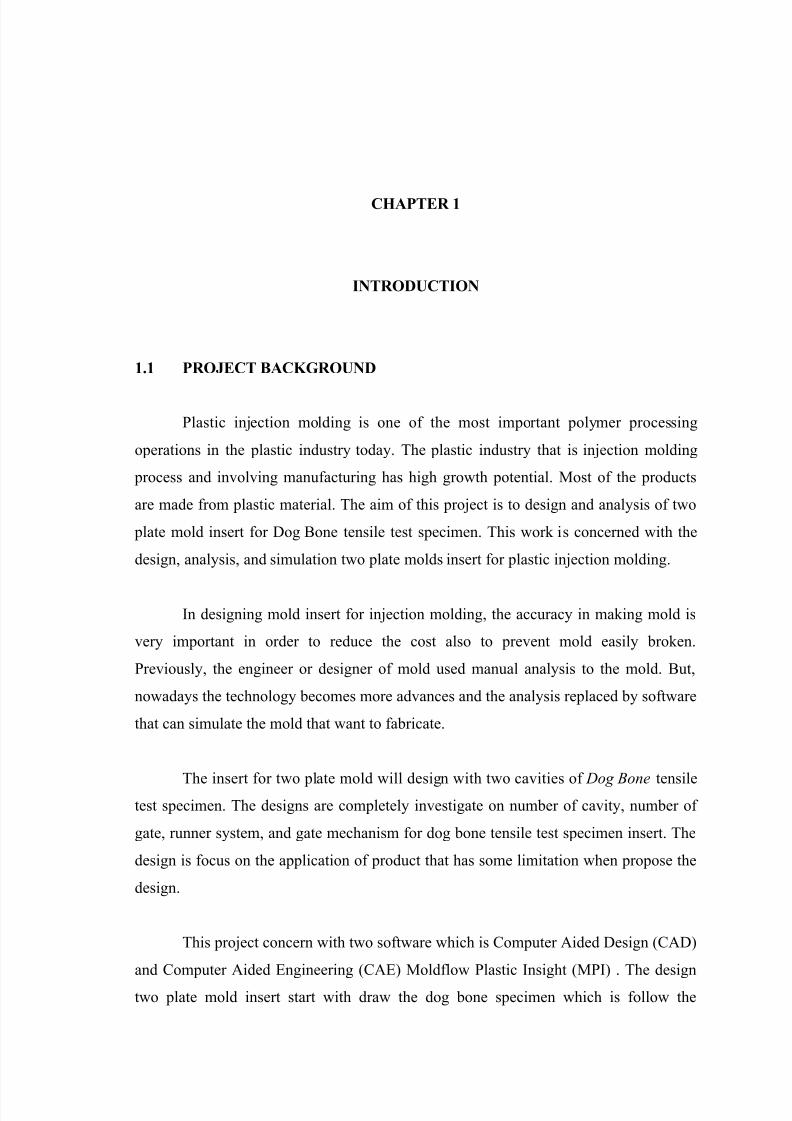
1.1 PROJECT BACKGROUND
Plastic injection molding is one of the most important polymer processing
operations in the plastic industry today. The plastic industry that is injection molding
process and involving manufacturing has high growth potential. Most of the products
are made from plastic material. The aim of this project is to design and analysis of two
plate mold insert for Dog Bone tensile test specimen. This work is concerned with the
design, analysis, and simulation two plate molds insert for plastic injection molding.
In designing mold insert for injection molding, the accuracy in making mold is
very important in order to reduce the cost also to prevent mold easily broken.
Previously, the engineer or designer of mold used manual analysis to the mold. But,
nowadays the technology becomes more advances and the analysis replaced by software
that can simulate the mold that want to fabricate.
The insert for two plate mold will design with two cavities of Dog Bone tensiletest specimen. The designs are completely investigate on number of cavity, number of
gate, runner system, and gate mechanism for dog bone tensile test specimen insert. The
design is focus on the application of product that has some limitation when propose the
design.
This project concern with two software which is Computer Aided Design (CAD)
and Computer Aided Engineering (CAE) Moldflow Plastic Insight (MPI) . The design
two plate mold insert start with draw the dog bone specimen which is follow the
8/13/2019 Mohd Aliff Mohd Radzi
http://slidepdf.com/reader/full/mohd-aliff-mohd-radzi 17/24
2
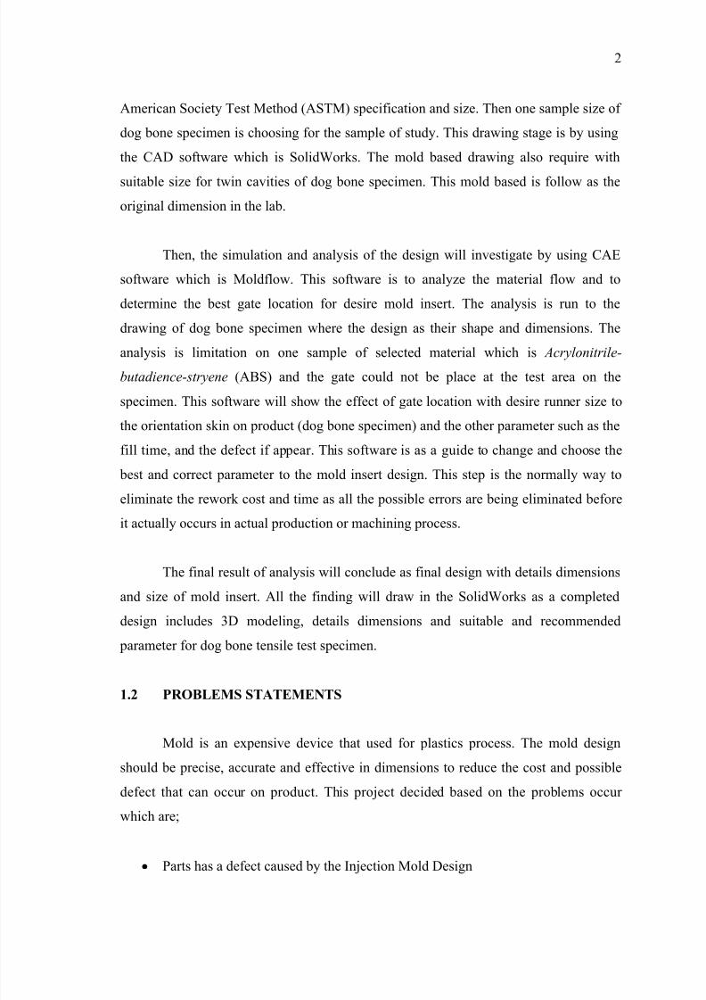
American Society Test Method (ASTM) specification and size. Then one sample size of
dog bone specimen is choosing for the sample of study. This drawing stage is by using
the CAD software which is SolidWorks. The mold based drawing also require with
suitable size for twin cavities of dog bone specimen. This mold based is follow as the
original dimension in the lab.
Then, the simulation and analysis of the design will investigate by using CAE
software which is Moldflow. This software is to analyze the material flow and to
determine the best gate location for desire mold insert. The analysis is run to the
drawing of dog bone specimen where the design as their shape and dimensions. The
analysis is limitation on one sample of selected material which is Acrylonitrile-
butadience-stryene (ABS) and the gate could not be place at the test area on the
specimen. This software will show the effect of gate location with desire runner size to
the orientation skin on product (dog bone specimen) and the other parameter such as the
fill time, and the defect if appear. This software is as a guide to change and choose the
best and correct parameter to the mold insert design. This step is the normally way to
eliminate the rework cost and time as all the possible errors are being eliminated before
it actually occurs in actual production or machining process.
The final result of analysis will conclude as final design with details dimensions
and size of mold insert. All the finding will draw in the SolidWorks as a completed
design includes 3D modeling, details dimensions and suitable and recommended
parameter for dog bone tensile test specimen.
1.2 PROBLEMS STATEMENTS
Mold is an expensive device that used for plastics process. The mold design
should be precise, accurate and effective in dimensions to reduce the cost and possible
defect that can occur on product. This project decided based on the problems occur
which are;
Parts has a defect caused by the Injection Mold Design
8/13/2019 Mohd Aliff Mohd Radzi
http://slidepdf.com/reader/full/mohd-aliff-mohd-radzi 18/24
3
More than three time mold testing require to balancing material flow into the
part especially in multi-cavities and family mold.
High costs on mold insert fabrication.
Precise and accurate dimensions of mold insert design require as desire product
shape.
The gate location is effected to reduce the defect on product or parts.
All the problems that were occurring during designing process should be solving
properly. Previously, the engineer and designer solve all the problem and difficulties by
get the reference or guidance from the past experience of earlier mold design and by
experienced engineers. The technology today has helps the engineer to solve all the
problems. This is come by using computer software where help the engineer easily
change or determine the optimum gate size, gate location and so on. This is directly will
reduce the time and cost of production.
1.3 PROJECT OBJECTIVE
The objectives of this project are:
1. To design Two Plate Molds insert for injection molding process.
2. To determine the best material flow for twin cavities to reduce the friction flow
during injections.
3. To determine the best gate location for less defect to test specimen.
1.4 PROJECT SCOPES
The Scopes for these projects generally focus on designing using CAD software
(SolidWorks) and analysis using CAE software (Moldflow) which is to find the best
design of mold insert as steps before fabrication. Firstly, the focus of analysis is the dog
bone specimen. This specimen used as a tensile test specimen where follows the
standard of American Standard Test Methods (ASTM). The sample size and type was
choosing based on that standard of ASTM.
8/13/2019 Mohd Aliff Mohd Radzi
http://slidepdf.com/reader/full/mohd-aliff-mohd-radzi 19/24
4
Next, this study used the specify CAE software for analysis the material flow
which is Moldflow Plastic Insight (MPI). MPI with 5.0 versions used to determine the
best gate location for the dog bone specimen. This software will show how the material
flows into the parts in order to determine the best location for the design.
This study was focus on design the best gate location for twin cavities of dog
bone specimen insert. This design is to reduce the possibility defects that can occur and
to have the effective design with less of product defect after mold insert fabrication. All
the design was focused for two plate mold as the title of this study.
Lastly, the analysis was performed by using selected engineering material which
is Acrylonitrile Butadiene Styrene (ABS). This material selected for one sample of
material for analysis and that is suitable for many applications for engineering works.
1.5 PROJECT PLAN
Gant chart for the project plan can be referring to appendix A1 for Gant Chart PSM I
and appendix A2 for Gant Chart PSM II.
This “Projek Sarjana Muda” (PSM) consists of two parts which are PSM 1 and
PSM 2. That is separate for first semester with PSM 1 and continues with PSM 2 on
second semester. PSM1: At beginning with receives the title of project from supervisor
and supervisor gives briefly explanations about that PSM title given. Supervisor give
briefly guide to make the schedule or task planning for the whole works for PSM.
Schedule management is needed for this project to make sure the project running in progress. Then, discussion with supervisor start focused on the project title about the
objective, problem statement, and scope of project. Next, the project progress continue
by start finding the information data and all related information to the project title by
reverse engineering study and literature review from web sites, journal, reference books,
supervisor and other relevant academic material that related to this project. To get the
clear view and very understand about the project, it is require studying more on material
that related to the project topic and spend more than two week to make a literature
review. The process of literature review in continuously move from one thing to another
8/13/2019 Mohd Aliff Mohd Radzi
http://slidepdf.com/reader/full/mohd-aliff-mohd-radzi 20/24
5
things. This is continuously until the project arrived to chapter 4 which is result of the
project. Every week and continuously, improvement of knowledge is needed to make
sure this project will be performing very well.
Continuing the progress, all the literature review related need to collect and get
focused to reduce the scopes of works. The literature review requires the information
and material about injection mold, mold components, injection mold design, mold
based, gating system, runner system, and the software that is required for this project.
The progresses continue with product or parts selection as a sample of product study for
this project. The sample of product which is Dog Bone tensile test specimen was
choosing. This product, scopes to standard dimension and shape follow the American
Society Test Method (ASTM) standard. Next, based on the size of selected product, the
suitable mold based size is determined which is available on our lab. The selected and
most suitable mold based is selected and do the dimensioning details with all
components These task will performed with suitable tools and equipments which are
ruler (mm), venire caliper and measuring tape (mm). All this dimensions is used as
references to redraw in CAD software to do the modeling and analysis by CAE
Moldflow Software. Next, drawing of selected sample of product and mold based as a
modeling and for analysis and design details. All these drawing were draw by CAD
software which is SolidWorks. This drawing is details with dimension as actual size as
an original product. The dimension was following the current parts and also gets the
reference of dog bone by ASTM standard. Next, the process continues with the material
selection as sample of product material to analyze the material flow. This material is
scopes to engineering plastic material which is using Acrylonitrilebutadiencestryene
(ABS) material. All the information and data collection and parameter require for this project progress will recorded as a reference for the analysis task on PSM 2. After that,
task is preparation of progress presentation and report writing chapter one, chapter two
and chapter three as a complete task for PSM 1. These tasks take two week to be finish.
In the presentation, the information and flow of project was explains to the panels. That
is details with project objective and scope that focus in. On that particular week,
preparations also include the slide presentation for the PSM 1 work progress
presentation.
8/13/2019 Mohd Aliff Mohd Radzi
http://slidepdf.com/reader/full/mohd-aliff-mohd-radzi 21/24
6
PSM 2: The project task for PSM 2 will continue follow as the planning. The
actual work and planning for PSM 2 were present at the beginning of the semester.
Project progress will be continuing with design the mold insert for dog bone tensile test
specimen. The designs start with determined the suitable runner system for dog bone
mold insert. The runner system will determine on the diameter and shape of cross-
section that is recommended and suitable as desire shape and size of dog bone
specimen. Next is determining the gating systems which are gate type, gate size and
gate location. Type of gate that will choose is based on the type of injection mold which
is two plate molds. Then the gate is selected for surface gate. The gate dimension will
determined based on the finding of type of gate selection. The types of gate will selected
and evaluate from several gate type that is possible for two plate mold. The final stage
on gate mechanism is the gate location. Next, the task continue with determine the
possible gate location for selected product (dog bone). This process requires the
software support to determine the best gate location for the dog bone part. This process
will run in several times with various locations to determine the most suitable location.
The sequence of analysis that will use is flow analysis to see the material flow in the
part. This process will details investigate in order to suite the applications and usage of
the part (dog bone). This process will take a few weeks to done it but it need to make in
fast for continue on next task. The data and result from the analysis will be as the
references to continue the design of mold insert of product (dog bone). The parameters
and data used are recorded in the table for proper reference and guides line. This stage is
to do the modeling of the inserts how it will machine or fabricated to the mold based.
This modeling can give the clear view of actual insert design like real. This modeling
also can be the benchmark of improvement in complete mold constructions for two
plate mold of dog bone insert. This task will performed with complete dimensioning anddrawing details as final works.
This is also important to avoid the ejector pins are located at wrong placed that
will cause the defect to the product during ejection process. The suitable number of
ejector pins also can be determined after the solid modeling of complete design.
The data and information will record as a result achieved. This result includes
the gate location, ejectors pins location, numbers of ejector pins, suitable runner size
8/13/2019 Mohd Aliff Mohd Radzi
http://slidepdf.com/reader/full/mohd-aliff-mohd-radzi 22/24
7
and some conclusion and discussion. This result achieve will be as a reference to future
works which is fabrication as a real products.
This is how the engineer or mold insert fabricate person do to avoid the mold
broke after fabrication done. This stage will observe the result that is capable for best
location of gate and runner size for our sample project.
Lastly, the final report writing and prepare the presentation. This takes about one
to two weeks to arrange and accomplish. A report is guided by FKM thesis format and
also guidance from supervisor. All task scheduled is take around two semesters to
complete. Before the complete report submission, we need to present all the results
achieve from PSM 2 to the panel. The project will evaluate and have some comment for
make a little bit modification for report done.
8/13/2019 Mohd Aliff Mohd Radzi
http://slidepdf.com/reader/full/mohd-aliff-mohd-radzi 23/24
8
CHAPTER 2
LITERATURE REVIEW
2.1 INTRODUCTION
The best way is the molds and parts designer must have a good knowledge on
the basic of injection molding process. It will help them to design for manufacturer and
not just a design which is very nice but it cannot be manufactured. The basic theory of
plastic injection molding including the injection molding machine, injection molding
process, injection molds, type of gates, plastic material, plastic parts design guideline,
and machining process in molds fabrications will discuss details in this chapter.
2.2 INJECTION MOLDS
2.2.1 Types of Injection Molds
The molds are the most important component of the injection molding process.
It will determine the finish size of the parts that is producing, the surface finish of the
final product and dictate just how well the injection molding process will run (L.Sorsand I.Balazs. 1989).
2.2.1.1 Cold Runner Injection Molds
The majority of plastic injection molds built using the cold runner type. In a cold
runner mold, the plastic melt is injected into the mold through a sprue and runner where
it enters each cavity in the mold. During the cooling stage of the injection molding
cycle, the plastic in the cavities, sprue and runner solidify. The sprue and runner become
8/13/2019 Mohd Aliff Mohd Radzi
http://slidepdf.com/reader/full/mohd-aliff-mohd-radzi 24/24
9
scrap in this type of injection mold. They are then ground into small pieces or pellets
and mixed with the virgin plastic for reuse. Cold runner injection molds are more
economical to build than hot runner molds, however they can be less economical to run
if the amount of plastic in the sprue and runner exceeds 35% of the plastic that is
injected into the part cavities (L.Sors and I.Balazs. 1989).
2.2.2 Two and Three-Plate Molds
Mold for plastic injection molding can be categorized into two main categories
that are two plate mold and three plate mold. Each type has a different design, function
and structure. The selection types of mold depend on types of product, function and
production capacity. The cost of mold fabrication also depends on the types of mold.
This study will discuss details on two-plate molds.
2.2.2.1 Two-Plate Molds
This kind of mold is used for parts that are typically gated on or around their
edge, with the runner in the same mold plate as the cavity. Two-plate mold can divided
into 3 category that is cold runner, hot runner and conventional. Figure 2.1 shows the
two-plate mold which are separated by one line called parting line into two side, core
side and cavity side. Core side content ejector pin, core insert which is moving after
plastic inject into the mold and the ejection bar will push the ejector pin and the ejector
pin then push the part out from the mold. Cavity side is a fixed side, not moving and
content feed system (sprue, runner and gate). Plastic material will injected from the
machine nozzle into a sprue bush and through the runner to the cavity. Moldtemperature controlled by temperature controller. That have 5 medium usually used to
control the mold temperature that is chiller (3°C to 35°C), normal water (35°C to 45°C),
hot water (45°C to 90°C), hot oil (90°C to 250°C) and ethylene glycol (90°C to 250°C)
(A.B. Glanvill and E.N. Denton. 1985).