Embed Size (px)
Citation preview

SCHOOL OF INNOVATIVE TECHNOLOGIES & ENGINEERINGDept. of Industrial Systems Engineering
Module Information Pack
B.Eng (Hons.) Electronic Engineering
Microprogramming
HCA2102C
Academic Year 2020/2021 – Semester 1(Blended Learning)

Programme Director: Mr. R. H. HeerasingProgramme Coordinator: Mr. R. H. HeerasingModule Coordinator: Mr. Rishi HeerasingModule Convenor: Mr. Rishi Heerasing
Office: Room G2.14 Level 2 SITE BLOCKPhone: 207 5250 ext. 124E-mail: [email protected]
Academic Tutoring: None F2F Classes Day and Time: Wednesdays: 13:00-16:00 G0.2Credits & Level: 4 credits, Level 2Pre-requisites (If applicable): NoneCo-requisites (If applicable): NoneMethod of Delivery & Frequency: 7 x 3 Hours F2F classes on odd-weeks, 7 x 2 Hours online
lectures on even weeks, 42 Hours Self-Study.Method & Criteria of Assessment: 100% Coursework (Assignment and Class Test)
Module Aims:
To introduce the basic terminology and architecture associated with Complex Instruction Set Computing with emphasis on the Intel® 80X86 family of microprocessor in computer systems.
To provide an understanding of Assembly Language Programming using development tools like Microsoft® MASM and Borland® TASM which comprise of Programmers Work Bench (PWB), Linker (ML) and InteractiveDebugger (CodeView).
To illustrate the concepts of macro-instructions and interrupts.
Learning Objectives and Outcomes:
Understand the technical literature, fundamental concepts and issues involved in microprocessors.
Understand the different memory addressing modes used by microprocessors.
Analyse and design assembler macro instructions. Understand basic program constructs like sequence, selection and
iteration. Understand how interrupts are used by microprocessors. Understand the different memory models available for microprocessors. Understand the structure and operation of the floating-point unit. Understand how to perform simple I/O operations

TENTATIVE MODULE SCHEDULE
Week Date Topics Covered
107/10/20
F2FBasic Concepts: Princeton v/s Hardware Architectures, RISC vs. CISC, Pipelining, Superscalar architectures.
214/10/20
OnlineAssembler Overview: Global Program Structure: .STACK, .DATA, .CODE segments.
321/10/20
F2FIntroduction to Macros: Macro for I/O; DOS function calls; Numeric I/O and Magic Numbers.
428/10/20
OnlineNo class ( SU activity week)
504/11/20
F2FArithmetic: Signed and unsigned integer operations, Addition, Subtraction
611/11/20
OnlineArithmetic: Multiplication, Division
718/11/20
F2FComparing & Branching: Decision-making; Conditional jumps and looping; Instruction timing.
825/11/20
OnlineSubprograms & Stack: Public Keyword, Call & Ret, Stack Operations.
902/12/20
F2FMacros and Program Testing: Macro declarations & expansion; Parameters; Pseudo-macros.
1009/12/20
OnlineAdvanced bit operations & Floating Point Unit: Shifts and Rotates,FPU Data and Stack, FPU Arithmetic and I/O.
1116/12/20
F2F Arrays: Addressing, Arrays, Byte Swapping
End of Year Break
1206/01/21
OnlineMemory Structure & Interrupts: Segments and Offset; Addressing modes; 80X86 Interrupt processing; Interrupts handlers.
1313/01/21
F2FClass Test (40% of module weight)
1420/01/21
Online Class Test Post-Mortem

READING LIST
RECOMMENDED TEXTS (as per availability in the UTM Resource Centre):
Jones W. (2002) Assembly Language, 3rd Ed., Dreamtech Press
Irvine R. (2003) Assembly Language for Intel-Based computers, 4th Ed.,
D5.1 IRV Ж
Mano M. (1997) Computer System Architecture, 3rd Ed., D4.4 MAN
Ж Download these ebooks at http://www.rishiheerasing.net/download/hardware.html
OTHER READING MATERIAL e.g. TEXTS/JOURNALS/ARTICLES/WEBSITES:
Intel 80X86 Instructions Set: http://library.n0i.net/hardware/intel80x86/
LECTURE NOTES
The following lecture notes are available at http://www.rishiheerasing.net/modules/hca2101/ln.html
The notes are in .pdf format so you will need Adobe Acrobat® Reader to view them. This reader can also be downloaded from the two above-mentioned sites in the Downloads Section.

Lecture 1
BASIC CONCEPTSThis module is an introduction to the low-level operation of microprocessor-based computer systems. We will cover the operation of the Central Processing Unit, Memory, and I/O devices. This module is primarily a programming module, however it will also focus on the understanding and operation of the hardware and advanced architectural concepts. The programming part of the module is in Assembly Language using the Intel® 80X86 as the target processor, and MS-DOS as the target operating environment. Many of the programming exercises in the labs are geared around programming and controlling input/output devices. The programming tools used will be Microsoft® MASM 6.15, and if time permits GNU NASM. The Microsoft tool use PWB (Programmer’s Workbench) as the IDE with CodeView as the debugger. You can always refer to my website at http://pages.intnet.mu/rhh or my intranet site at http://intraweb/~rh on which module materials will be posted. These will include lecture notes, assignments, and other resources.Evolution of computers and the development of the microprocessor
• Originally, computer was a job description. It meant someone whose job was to calculate things.• With the invention of programmable machines, the word changed to mean the machine that did the calculation.• Early computers required some rewiring to change operations. Eventually, the stored program concept was invented. Two contrasting architectural types
Invention of Microprocessor
• Contains all of the functions of the CPU on a single integrated circuit.o 8088: 16 bits code and data, real mode operationo 80286: 16 bits code and data, real and protected mode operationo 80386: 32 bits code and data, real mode, virtual 86 mode and protected modeo 80486: integrates math co-processor functions with on same chipo Pentium and beyond: Superscalar architecture
Page 1 of 14
Page 4 of 80
Lecture 1
System Block Diagram
CPU – Central Processing UnitThe CPU controls the operation of the computer: executes instructions, generates timing to control operation of rest of system. Various kinds of co-processors exist in some systems, which extend the instruction set of the main CPU. Memory Memory consists of array of memory locations. It can be organized as bits, bytes, words or double words. Types of Memory: RAM: SRAM, DDRAM, RDRAM and ROM: EPROM, EEPROM, Flash MemoryInput/Output Memory mapped vs. I/O mapped Some processors have a separate address space for I/O devices (e.g. 8080, Z80, 80x86), other processors have only a memory address space and expect that I/O devices will be in the same address space as memory. (e.g. 68HC11, 68000) Serial I/O Data is presented in a bit serial format. Varies with word size, and bit order as well as type of clocking e.g. Asynchronous, RS-232, Synchronous, USB, PS/2 keyboard and mouse Parallel I/O Data is presented with all data bits at the same time on multiple lines e.g. Printer port, SCSI interface Interrupt Logic Used by high priority I/O devices to break into the CPU’s stream of execution and temporarily cause it to execute other code. System Bus - Used to interface between different parts of the computer system.Address Bus: Carries address information from the CPUData Bus: Carries instructions and data between the CPU and memory and I/O devices Control Bus: Carries control and timing signals between the CPU and the rest of the system. Microprocessor Operation
Machine Cycles: Instruction Fetch, Information Decode, Information Execute, Information Store Bus Cycles:Memory Read, Memory Write, I/O Read, I/O Write, Interrupt Acknowledged
Addressing Modes The microprocessor instructions operate on data. The addressing mode for the instruction informs the processor how to find the data (operands) for the instruction to operate on. Page 2 of 14
Page 5 of 80
Lecture 1
Register: The operand is contained in one of the processor registers: e.g. mov ax,bx Immediate: The operand is included as part of the instruction. e.g.: mov ax, 1 Direct: The address of the data is included in the instruction. e.g.: mov ax,var1 Register Indirect: The address of the data is specified by one of the following registers: BX, SI, DI. e.g.: mov ax,[bx] Indexed: The address of the data is contained in an index register, plus an optional offset. e.g.: mov ax,[si+5] Based: The address of the data is contained in a base register, plus an optional offset. e.g.: mov ax,[bp+5] Based Indexed: The address of the data is contained in the sum of a base register plus an index register, plus an optional offset. e.g.: mov ax,[bx][di]+5 InterruptsThere are three basic types of interrupt: Hardware Interrupts: Generate by external hardware associated with some I/O device. NMI – Non-maskable interrupt; is generated by signal on the NMI pin and can not be disabled in software. Uses vector 2. Regular interrupt: Generated by signal on the INT pin on the processor. Vector is supplied by external interrupt controller hardware in response to interrupt acknowledge cycle by processor. Software Interrupts: These are generated by the execution of an instruction in the program. Exceptions: These generally indicate errors detected by the processor during the execution of the program.Improving Computer Performance: How can we make computers faster?
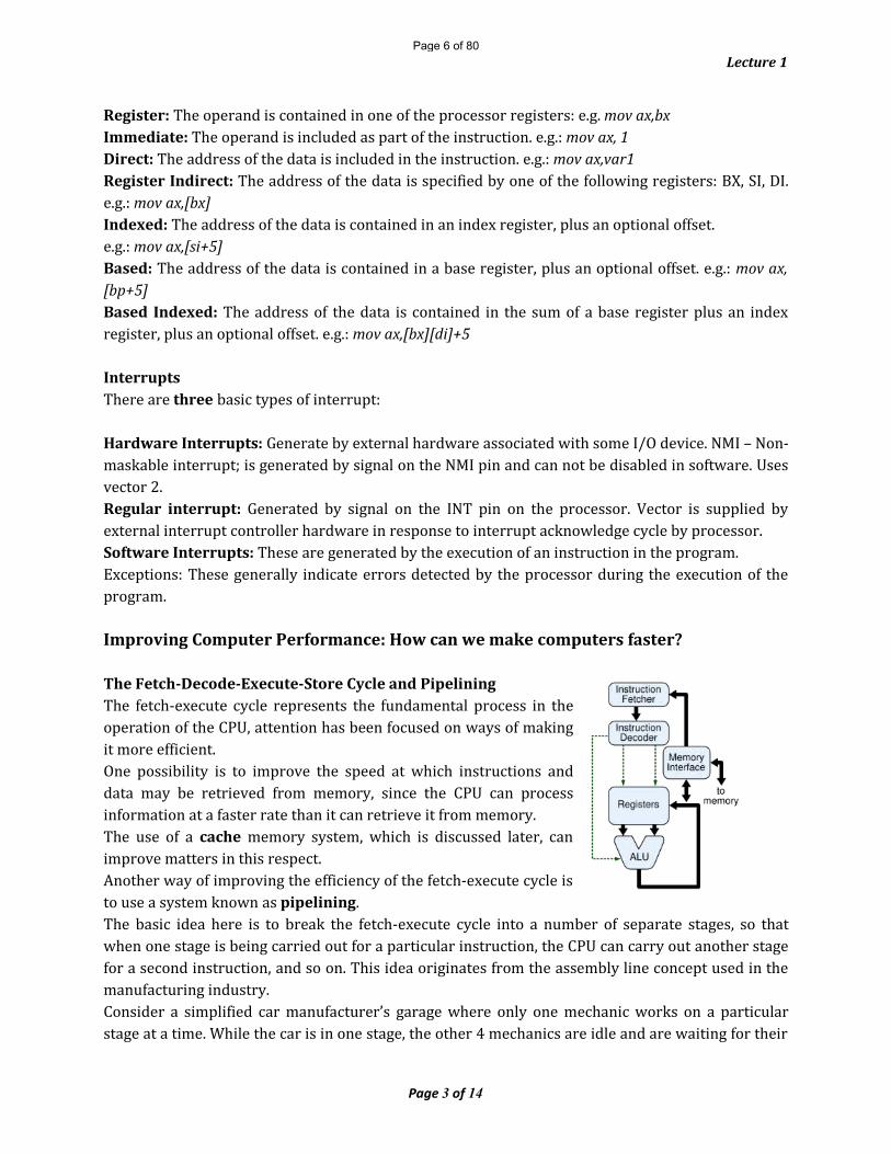
The Fetch-Decode-Execute-Store Cycle and PipeliningThe fetch-execute cycle represents the fundamental process in the operation of the CPU, attention has been focused on ways of making it more efficient.One possibility is to improve the speed at which instructions and data may be retrieved from memory, since the CPU can process information at a faster rate than it can retrieve it from memory.The use of a cache memory system, which is discussed later, can improve matters in this respect.Another way of improving the efficiency of the fetch-execute cycle is to use a system known as pipelining.The basic idea here is to break the fetch-execute cycle into a number of separate stages, so that when one stage is being carried out for a particular instruction, the CPU can carry out another stage for a second instruction, and so on. This idea originates from the assembly line concept used in the manufacturing industry.Consider a simplified car manufacturer’s garage where only one mechanic works on a particular stage at a time. While the car is in one stage, the other 4 mechanics are idle and are waiting for their Page 3 of 14
Page 6 of 80
Lecture 1
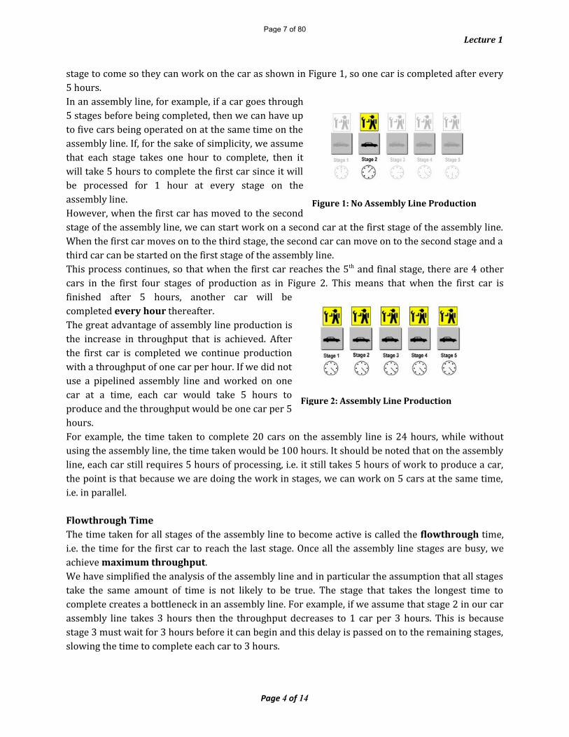
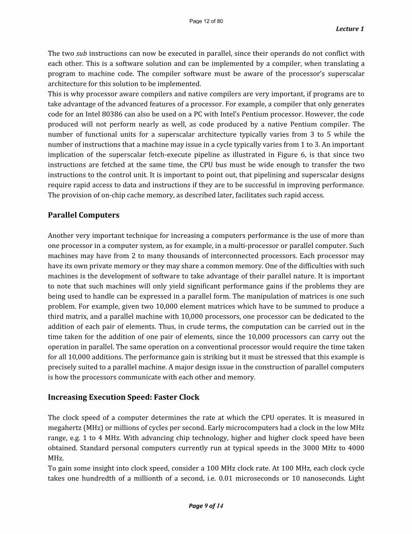
stage to come so they can work on the car as shown in Figure 1, so one car is completed after every 5 hours.In an assembly line, for example, if a car goes through 5 stages before being completed, then we can have up to five cars being operated on at the same time on the assembly line. If, for the sake of simplicity, we assume that each stage takes one hour to complete, then it will take 5 hours to complete the first car since it will be processed for 1 hour at every stage on the assembly line.However, when the first car has moved to the second stage of the assembly line, we can start work on a second car at the first stage of the assembly line. When the first car moves on to the third stage, the second car can move on to the second stage and a third car can be started on the first stage of the assembly line.This process continues, so that when the first car reaches the 5th and final stage, there are 4 other cars in the first four stages of production as in Figure 2. This means that when the first car is finished after 5 hours, another car will be completed every hour thereafter.The great advantage of assembly line production is the increase in throughput that is achieved. After the first car is completed we continue production with a throughput of one car per hour. If we did not use a pipelined assembly line and worked on one car at a time, each car would take 5 hours to produce and the throughput would be one car per 5 hours.For example, the time taken to complete 20 cars on the assembly line is 24 hours, while without using the assembly line, the time taken would be 100 hours. It should be noted that on the assembly line, each car still requires 5 hours of processing, i.e. it still takes 5 hours of work to produce a car, the point is that because we are doing the work in stages, we can work on 5 cars at the same time, i.e. in parallel.Flowthrough TimeThe time taken for all stages of the assembly line to become active is called the flowthrough time, i.e. the time for the first car to reach the last stage. Once all the assembly line stages are busy, we achieve maximum throughput.We have simplified the analysis of the assembly line and in particular the assumption that all stages take the same amount of time is not likely to be true. The stage that takes the longest time to complete creates a bottleneck in an assembly line. For example, if we assume that stage 2 in our car assembly line takes 3 hours then the throughput decreases to 1 car per 3 hours. This is because stage 3 must wait for 3 hours before it can begin and this delay is passed on to the remaining stages, slowing the time to complete each car to 3 hours.
Page 4 of 14
Figure 1: No Assembly Line Production
Figure 2: Assembly Line Production
Page 7 of 80

Lecture 1
Clock periodWe can express this by saying the clock period of the assembly line (time between completed cars) is 3 hours. The clock period, denoted by Tp, of an assembly line is given by the formula:Tp = max(t1, t2, t3, ....., tn)where ti is the time taken for the ith stage and there are n stages in the assembly line. This means that the clock period is determined by the time taken by the stage that requires the most processing time.In a non-pipelined system, the total time T, taken to complete a car, is the sum of the time for the individual stages, i.e.T = t1+ t2 + t3 + ... + tnIn our example, if all stages take 1 hour to complete, then T = 5 hours, it takes 5 hours to complete every car.If stage 2 takes 3 hours and the other stages take 1 hour to complete then T rises to 7 hours and it will take 7 hours to complete every car.
ThroughputWe can define the throughput of an assembly line to be 1/Tp. Using this definition, the throughput for our assembly line where all stages take 1 hour is 1/1, i.e. 1 car/hour. If we assume stage 2 takes 3 hours to complete, the throughput falls to 1/3 or .333 cars/hour. For non-assembly line production the respective throughputs are 1/5 or .2 cars/hour and 1/7 or .143 cars/hour.PipeliningThe same principle as that of the assembly line can be applied to the fetch-execute cycle of a processor where we refer to it as pipelining.1. Fetch an instruction from memory2. Decode the instruction using CU3. Execute the instruction using ALU4. Store result in either memory or write-back to register
Assuming each stage takes one clock cycle, then in a non-pipelined system, we use 5 cycles for the first instruction, followed by 5 cycles for the second instruction and so on, as illustrated in Figure 3:
Figure 3: Non-pipelined CPU. It takes 15 cycles to complete 3 instructions
Page 5 of 14
Page 8 of 80

Lecture 1
The throughput for such a system would be 1 instruction per 5 cycles. If we adopt the assembly line principle, then we can improve the throughput dramatically. Figure 4 illustrates the fetch-execute cycle employing pipelining.
Figure 4: CPU with pipeliningUsing pipelining, we overlap the processing of instructions, so that while the first instruction is in the decode stage; the second instruction is being fetched. While the first instruction is in the execute stage, the second instruction is in the decode stage and the third instruction is being fetched.After the first 5 cycles, the first instruction is completed and thereafter an instruction is completed on every cycle as opposed to a throughput of 5 cycles per instruction in a non-pipelined system. Again, as in the assembly line example, each instruction still takes the same number of cycles to complete, the gain comes from the fact that the CPU can operate on instructions in the different stages in parallel. The clock period and throughput of a pipeline are as defined for the assembly line above:Clock period Tp = max(t1, t2, t3, ....., tn) for n stage pipelineThroughput = 1/TpThe above description is quite simplified, ignoring the fact for example that all stages may not be completed in a single cycle. It also omits stages that arise in practice such as an operand fetch stage, which is required to fetch an operand from memory, or a write back stage to store the result of an ALU operation in a register or in memory. In practice, pipelined systems range from having 3 to 10 stages, for example, Intel’s Pentium microprocessor uses a 5-stage pipeline for integer instructions. There are difficulties in pipelining that would not arise on a factory assembly line, due to the nature of computer programs. Consider the following 3 instructions in a pipeline:
jg label (if previous comparison is positive then jump to label)mov y, 0mov x, 3
label: …..When the jg instruction is being executed, the following two instructions will be in earlier stages, one being fetched and the other being decoded. However, if the jg instruction evaluates the condition to be true, it means that the two move instructions will not be executed and new instructions have to be loaded, starting at the instruction indicated by label. This means that we have to flush the pipeline and reload it with new instructions. The time taken to reload the pipeline is called the branch penalty and may take several clock cycles. Branch instructions occur very frequently in programs and so it is important to process them as efficiently as possible.Page 6 of 14
Page 9 of 80

Lecture 1
A technique known as branch prediction can be used to alleviate the problem of conditional branch instructions, whereby the system "guesses" the outcome of a conditional branch evaluation before the instruction is evaluated and loads the pipeline appropriately. Depending on how successfully the guess is made, the need for flushing the pipeline can be reduced. When the branch has been evaluated, the processor can take appropriate action if a wrong guess was made. In the event of an incorrect guess, the pipeline will have to be flushed and new instructions loaded.Branch prediction is used on a number of microprocessors such as the Pentium and PowerPC. Successful guesses ranging from 80% to 85% of the time are cited for the Pentium microprocessor. Another technique is to use delayed branching. In this case, the instruction following the conditional jump instruction is always executed.For example, if the conditional jump instruction is implementing a loop by jumping backwards, it may be possible to place one of the loop body instructions after the conditional jump instruction. If a useful instruction cannot be placed here, then a nop instruction can be used.Increasing Execution Speed: More HardwareConsider the following two instructions:
add i, 10 (this is equivalent to i=i+10)add x, y (this is equivalent to x=x+y)In a simple processor these instructions would be executed in sequence by transferring the operands to the ALU and carrying out the addition operations.One way of speeding things up is to have to two ALUs so that the instructions can be carried out at the same time, i.e. the two ALUs can carry out the instructions in parallel. This idea is now widely employed by the current generation of microprocessors such as the Pentium, PowerPC and Alpha.The term superscalar is used to describe architecture with two or more functional units which can carry out two or more instructions in the same clock cycle.These may include integer units (IUs), floating-point units (FPUs) and branch processing units (BPUs, devoted to handling branch instructions).The micro-architecture of a hypothetical superscalar processor is illustrated in Figure 5. The term micro-architecture is used to refer to the internal architecture of a processor.
Page 7 of 14
Figure 5: Micro-architecture of a superscalar processor
Page 10 of 80

Lecture 1
The processor shown in Figure 5 has three execution units and could execute 3 instructions concurrently, in theory. The register file is the collective name given to the CPU’s registers. A processor with an on-chip FPU would have a separate set of floating-point registers (FPRs) in addition to the usual general purpose registers (GPRs).The cache memory is used to speed up the processor’s access to instructions and data (see later). The extra functional units allow the CPU carry out more operations per clock cycle. Figure 6 illustrates the fetch-execute cycle for a superscalar architecture, with two functional units operating in parallel.
As can be seen from Figure 6, two instructions are in each stage of the pipeline at the same time, doubling the throughput of the pipeline, in theory. If we consider cycle 3 we can see that the processor is handling six stages of six instructions at the same time. In practice, this can give rise to a number of problems, since there are situations that arise, which mean that instructions cannot be executed in parallel. One problem that arises is that of inter-instruction dependencies.Consider the following three sequential instructions:sub r1, x (this is equivalent to r1=r1-x)add r1, 2 (this is equivalent to r1=r1+2)sub r0, r3 (this is equivalent to r0=r0-r3)The first two instructions (add and sub) cannot be carried out in parallel as they both modify the same operand, r1, giving rise to a data dependency. A data dependency arises between two instructions if the destination operand of one instruction is accessed by the other instruction. In this particular example, a solution is possible called instruction reordering (scheduling) because by reordering the instructions in the sequence:sub r1, xsub r0, r3add r1, 2
Page 8 of 14
Figure 6: Superscalar Architecture fetch-execute cycle
Page 11 of 80
Lecture 1
The two sub instructions can now be executed in parallel, since their operands do not conflict with each other. This is a software solution and can be implemented by a compiler, when translating a program to machine code. The compiler software must be aware of the processor’s superscalar architecture for this solution to be implemented.This is why processor aware compilers and native compilers are very important, if programs are to take advantage of the advanced features of a processor. For example, a compiler that only generates code for an Intel 80386 can also be used on a PC with Intel’s Pentium processor. However, the code produced will not perform nearly as well, as code produced by a native Pentium compiler. The number of functional units for a superscalar architecture typically varies from 3 to 5 while the number of instructions that a machine may issue in a cycle typically varies from 1 to 3. An important implication of the superscalar fetch-execute pipeline as illustrated in Figure 6, is that since two instructions are fetched at the same time, the CPU bus must be wide enough to transfer the two instructions to the control unit. It is important to point out, that pipelining and superscalar designs require rapid access to data and instructions if they are to be successful in improving performance. The provision of on-chip cache memory, as described later, facilitates such rapid access.Parallel ComputersAnother very important technique for increasing a computers performance is the use of more than one processor in a computer system, as for example, in a multi-processor or parallel computer. Such machines may have from 2 to many thousands of interconnected processors. Each processor may have its own private memory or they may share a common memory. One of the difficulties with such machines is the development of software to take advantage of their parallel nature. It is important to note that such machines will only yield significant performance gains if the problems they are being used to handle can be expressed in a parallel form. The manipulation of matrices is one such problem. For example, given two 10,000 element matrices which have to be summed to produce a third matrix, and a parallel machine with 10,000 processors, one processor can be dedicated to the addition of each pair of elements. Thus, in crude terms, the computation can be carried out in the time taken for the addition of one pair of elements, since the 10,000 processors can carry out the operation in parallel. The same operation on a conventional processor would require the time taken for all 10,000 additions. The performance gain is striking but it must be stressed that this example is precisely suited to a parallel machine. A major design issue in the construction of parallel computers is how the processors communicate with each other and memory.Increasing Execution Speed: Faster ClockThe clock speed of a computer determines the rate at which the CPU operates. It is measured in megahertz (MHz) or millions of cycles per second. Early microcomputers had a clock in the low MHz range, e.g. 1 to 4 MHz. With advancing chip technology, higher and higher clock speed have been obtained. Standard personal computers currently run at typical speeds in the 3000 MHz to 4000 MHz. To gain some insight into clock speed, consider a 100 MHz clock rate. At 100 MHz, each clock cycle takes one hundredth of a millionth of a second, i.e. 0.01 microseconds or 10 nanoseconds. Light
Page 9 of 14
Page 12 of 80

Lecture 1
travels at about 1 foot per nanosecond, so one clock cycle of a 100 MHz clock takes the same amount of time as the time light takes to travel 10 feet!The Von Neumann bottleneckIt should be noted that increasing the clock speed does not guarantee significant performance gains. This is because the speed of the processor is effectively determined by the rate at which it can fetch instructions and data from memory. Thus if the processor spends 90% of its time waiting on memory, the performance gained by doubling the processor speed (without improving the memory access time) is only 5%.For example, assume a task takes 100 units of time, and 90 units are spent waiting on memory access with 10 units spent on CPU processing. By doubling the CPU speed, CPU processing time is reduced to 5 units and so the overall time is reduced to 95 time units, i.e. a 5% improvement. It is obviously important then to reduce the time the CPU has to wait for memory accesses.This is known as the Von Neumann bottleneck - caused by the mismatch in speed between the CPU and memory.The CPU can process data at a low nanosecond rate while RAM can only deliver it at a high nanosecond rate. For example, if RAM delivers data to the CPU at a rate of 100ns per data item (10 million items per second!) and the CPU can consume data at say 5ns per item, then the CPU will still spend 95% of its time waiting on memory.I/O DelaysThe processor will also usually have to wait for I/O operations to complete and indeed it is usually the case that I/O speeds determine the speed of program execution. Recall that it is of the order of 100,000 times slower to retrieve data from disk than it is to retrieve it from memory. This means that for programs that carry out I/O, the processor is idle most of the time, waiting for the I/O operations to complete. This in turn, means that using a more powerful processor to execute such programs, results in very little gain in overall execution speed.Improving Memory Access Time: Cache memoryOne way of improving memory access time involves the use of a cache memory system. The processor operates at its maximum speed if the data to be processed is in its registers. Unfortunately, register storage capacity is very limited and so memory is used to store programs and data. One, very effective way of overcoming the slow access time of main memory, is to design a faster intermediate memory system that lies between the CPU and main memory. Such memory is called cache memory (or simply cache) and it may be visualised as in Figure 8.
Page 10 of 14
Page 13 of 80
Lecture 1
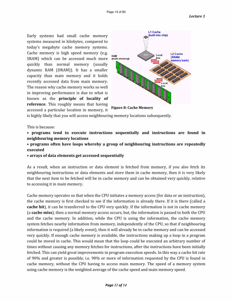
Early systems had small cache memory systems measured in kilobytes, compared to today’s megabyte cache memory systems. Cache memory is high speed memory (e.g. SRAM) which can be accessed much more quickly than normal memory (usually dynamic RAM (DRAM)). It has a smaller capacity than main memory and it holds recently accessed data from main memory. The reason why cache memory works so well in improving performance is due to what is known as the principle of locality of reference. This roughly means that having accessed a particular location in memory, it is highly likely that you will access neighbouring memory locations subsequently. This is because:• programs tend to execute instructions sequentially and instructions are found in neighbouring memory locations• programs often have loops whereby a group of neighbouring instructions are repeatedly executed• arrays of data elements get accessed sequentially As a result, when an instruction or data element is fetched from memory, if you also fetch its neighbouring instructions or data elements and store them in cache memory, then it is very likely that the next item to be fetched will be in cache memory and can be obtained very quickly, relative to accessing it in main memory.Cache memory operates so that when the CPU initiates a memory access (for data or an instruction), the cache memory is first checked to see if the information is already there. If it is there (called a cache hit), it can be transferred to the CPU very quickly. If the information is not in cache memory (a cache miss), then a normal memory access occurs, but, the information is passed to both the CPU and the cache memory. In addition, while the CPU is using the information, the cache memory system fetches nearby information from memory, independently of the CPU, so that if neighbouring information is required (a likely event), then it will already be in cache memory and can be accessed very quickly. If enough cache memory is available, the instructions making up a loop in a program could be stored in cache. This would mean that the loop could be executed an arbitrary number of times without causing any memory fetches for instructions, after the instructions have been initially fetched. This can yield great improvements in program execution speeds. In this way a cache hit rate of 90% and greater is possible, i.e. 90% or more of information requested by the CPU is found in cache memory, without the CPU having to access main memory. The speed of a memory system using cache memory is the weighted average of the cache speed and main memory speed.
Page 11 of 14
Figure 8: Cache Memory
Page 14 of 80

Lecture 1
For example, assume a 100 ns delay for main memory and 20 ns delay for cache memory with a 90% hit rate, then the apparent speed of memory access is (0.9 * 20) + (0.1* 100) = 28ns.This is a significant improvement in memory access performance, since the access time is now on average 28ns as opposed to 100ns if cache memory was not used. Cache memory is now also included on the CPU chip (on-chip cache) of many microprocessors such as Intel’s Pentium microprocessors, Digital’s Alpha microprocessor and the IBM/Apple PowerPC microprocessor. Since the cache memory is on the CPU chip, the speed of cache memory access is improved over that of off-chip cache memory. The capacity of on-chip cache memory varies from 128 KB to around 2 MB at the moment while off-chip cache memory has disappeared. Computers may use separate memories to store instructions and data and such architecture is called a Harvard Architecture because this idea emerged from machines built at Harvard University. Instructions and data may be stored in the same cache memory which is referred to as a unified cache memory. Alternatively, separate caches for instructions and data may be maintained along the lines of the Harvard Architecture. The advantage of the Harvard Architecture is that instructions and data can be fetched simultaneously, i.e. in parallel, since they will be connected to the other CPU components by separate buses.Measuring Computer PerformanceHow can we compare the performance of different computer systems? It is important to consider the performance of a computer system as a whole, including both the hardware and software and not just to consider the performance of the components of the system in isolation. It is very important to understand that measuring computer performance is a very difficult problem. There are a number of criteria that can be used for measuring the performance of a computer system and it is a non-trivial matter as to how to weigh up the relative importance of these criteria when comparing two computer systems. In addition, it is not easy to obtain totally objective information about different manufacturers’ machines or to get the information in a form that makes it easy to use for comparison purposes. Computer Performance MetricsThere are a number of ways of measuring the performance of a computer system or indeed that of the components that make up a computer system. One common measure is processor speed. The question of how to measure processor speed is not as simple as it appears. One simple measure is the number of instructions that can be executed per second, expressed in millions of instructions per second or MIPS. So, a given processor might have a processor speed of 5 MIPS, i.e. it can execute 5 million instructions per second. But, all instructions do not take the same amount of execution time. An instruction to clear a register might take 1 clock cycle. A multiplication instruction might take more than 10 clock cycles. The way to compute the MIPS rate more usefully is to calculate the average time the processor takes to execute its instructions, weighted by the frequency with which each instruction is used. However, the frequency of instruction usage depends on the software being used. So for example, word processing software would not require much use
Page 12 of 14
Page 15 of 80
Lecture 1
of a multiplication instruction whereas spreadsheet software would be more likely to use many multiplication instructions. When we compare the MIPS rate of two different machines, we must ensure that they are counting the same type of instructions. Another problem with the MIPS metric, is that the amount of work an individual instruction carries out, varies from processor to processor. For example, a single VAX add instruction is capable of adding two 32-bit memory variables and storing the result in a third memory variable, whereas a machine such as the 8086 requires three instructions (e.g. an add and two mov instructions) to accomplish the same task. Naively counting the number of add instructions that can be executed per second on these two machine will not give a true picture of either machines performance. We must also remember to take account of the processor word size when comparing instruction counts. A 32-bit processor is a more powerful machine than a 16-bit processor with the same MIPS rate, since it can operate on 32-bit operands as opposed to 16-bit operands. Similarly, a 64-bit processor will be more powerful than a 32-bit processor with the same MIPS rating.Another metric that is similar to the MIPS rate is the FLOPS or floating-point operations per second rate which is expressed in megaflops (MFLOPS) and gigaFLOPS (GFLOPS). This metric is used particularly for machines targeted at the scientific/engineering community where a lot of applications software requires large amounts of floating-point arithmetic executed more quickly than others (e.g. addition versus division). Like the MIPS metric, the FLOPS metric needs to be approached with caution. The MIPS and MFLOPS metrics are concerned with processor speed. The processor is a crucial component of a computer system when it comes to performance measurement but it is not the only one and, in fact, it may not be the determining factor of the performance of a system. Other components are the memory and I/O devices whose performances are also crucial to the overall system performance. For example, a database application may require searching for information among millions of records stored on hard disk. The dominant performance metric for such an application is the speed of disk I/O operations. In such an application, the CPU spends most of its time waiting for disk I/O operations to complete. If we use a faster processor without increasing the speed of the disk I/O operations, then the overall improvement in performance will be negligible. I/O performance may be measured in terms of the number of megabytes that can be transferred per second (I/O bandwidth). This can be deceptive, as the maximum transfer rate quoted may not be achieved in practice. Take disk I/O, if the information required is stored on different tracks, then the seek time to move the head to the required tracks will slow I/O down considerably, whereas if the information is on the same track it can be transferred much more quickly. Another measure is the number I/O operations that can be completed per second, which can take account of the fact that the information may not be conveniently available on disk. Memory performance is often measured in terms of its access time, i.e. the time taken to complete a memory write or read operation which is in the 10 to 100 ns range. The amount of memory present is also a very important factor in system performance. The larger the amount of memory present, the less likelihood for page faults to occur in a virtual memory system. Overall system performance is determined by the performance of the processor, memory and I/O devices as well as the operating system and applications software performance. One measure of system performance to take account of the processor, memory and I/O performance is the number of transactions per second (TPS) that the system can cope with. A transaction might be defined as the amount of work required to retrieve a customer record from disk, update the record and write it
Page 13 of 14
Page 16 of 80

Lecture 1
back to disk, as modelled on a typical bank transaction. System performance can also be evaluated by writing benchmark programs and running the same benchmark program on a series of machines. A benchmark program is one written to measure some aspect of a computer’s performance. For example, it might consist of a loop to carry out 1 million floating-point additions or a loop to carry out a million random read/write operations on a disk file. The time taken to execute the benchmark program gives a measure of the computer system’s performance. By constructing a number of such programs for the different aspects of a systems performance, a suite of benchmarks may be developed that allow different computer systems to be compared. Benchmark programs are also used to test the performance of systems software such as compilers. The size of the executable file produced by the compiler and the efficiency of the machine code are two metrics that are used to compare compilers. Another system performance measure is the SPECmark which is obtained in a similar fashion to the use of benchmark programs, except instead of using contrived benchmark programs, a suite of ten real world application programs are used (these include a compiler application, a nuclear reactor simulation and a quantum chemistry application). SPECmarks are used by companies such as Sun and Hewlett Packard to measure the performance of their workstations. One difficulty about using benchmarks and SPECmarks to evaluate system performance is that you are dependent on a compiler to translate the programs into efficient machine code for the computer under evaluation. However, compilers are not all equally efficient and particularly with the advent of new processor features such as multiple functional units capable of parallel operation, compiler writers have a complex task in designing good so-called optimising compilers. The code produced by a poor quality compiler can run significantly slower and use more memory than code produced by a good compiler. A computer manufacturer may have benchmark programs optimised for a particular machine so that the machine’s performance is apparently superior to another machine running the same benchmark programs which have not, however, been optimised for the second machine! In addition to the effects of the compiler, the operating system will also influence the performance of a computer system. In the case, where two computer systems running different operating systems, are being evaluated, care must be taken to ensure that both operating systems are properly configured. For example, a good machine with an efficient operating system may perform poorly as a result of having insufficient memory allocated to user programs, in comparison to a less powerful machine which has been expertly tuned to run its programs. Other non-performance issues that arise when comparing computer systems are the actual cost of the system, and its reliability together with the availability of hardware and software support. Computer systems fail due to either hardware or software problems, or both. It is fundamentally important to take account of computing failures, from the moment of evaluating a new system right through to its day to day operation. There’s no point in having the most sophisticated computer system in the world, if when it fails, you cannot get it operational again, in a short period of time. In summary, evaluating computer system performance is fraught with difficulties and the use of apparently simple metrics such as MIPS and MFLOPS can be quite misleading. The reality is that there is no easy alternative to that of running real world application programs (preferably the ones you wish to use) and choosing the system which best matches the performance criteria that you have laid down.Page 14 of 14
Page 17 of 80
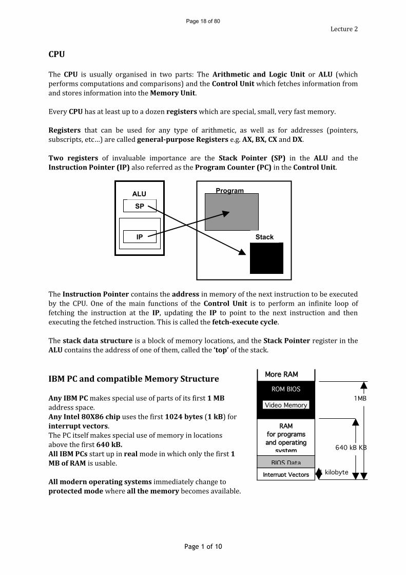
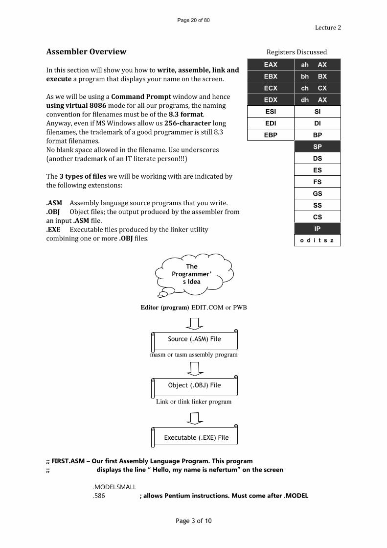
Lecture 2CPU The CPU is usually organised in two parts: The Arithmetic and Logic Unit or ALU (which performs computations and comparisons) and the Control Unit which fetches information from and stores information into the Memory Unit.Every CPU has at least up to a dozen registers which are special, small, very fast memory.Registers that can be used for any type of arithmetic, as well as for addresses (pointers, subscripts, etc…) are called general-purpose Registers e.g. AX, BX, CX and DX.Two registers of invaluable importance are the Stack Pointer (SP) in the ALU and the Instruction Pointer (IP) also referred as the Program Counter (PC) in the Control Unit.
The Instruction Pointer contains the address in memory of the next instruction to be executed by the CPU. One of the main functions of the Control Unit is to perform an infinite loop of fetching the instruction at the IP, updating the IP to point to the next instruction and then executing the fetched instruction. This is called the fetch-execute cycle.The stack data structure is a block of memory locations, and the Stack Pointer register in the ALU contains the address of one of them, called the ‘top’ of the stack.IBM PC and compatible Memory Structure
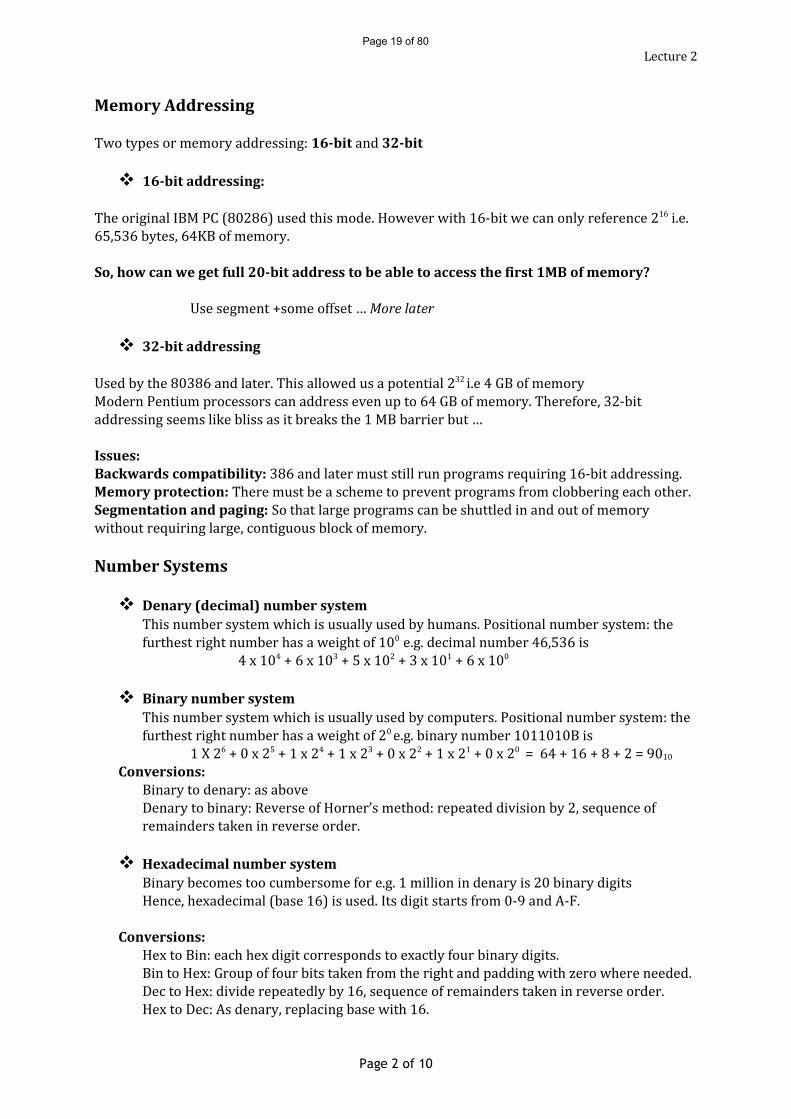
Any IBM PC makes special use of parts of its first 1 MB address space.Any Intel 80X86 chip uses the first 1024 bytes (1 kB) for interrupt vectors. The PC itself makes special use of memory in locations above the first 640 kB.All IBM PCs start up in real mode in which only the first 1 MB of RAM is usable.All modern operating systems immediately change to protected mode where all the memory becomes available.
Page 1 of 10
SP
ALU
CUIP
Program
Stack
Interrupt Vectors
BIOS Data
RAMfor programs and operating
system
ROM BIOS
Video Memory
1 kilobyte
640 kB KB
1MB
More RAM
Page 18 of 80
Lecture 2Memory AddressingTwo types or memory addressing: 16-bit and 32-bit
16-bit addressing: The original IBM PC (80286) used this mode. However with 16-bit we can only reference 216 i.e. 65,536 bytes, 64KB of memory.So, how can we get full 20-bit address to be able to access the first 1MB of memory?Use segment +some offset … More later
32-bit addressingUsed by the 80386 and later. This allowed us a potential 232 i.e 4 GB of memoryModern Pentium processors can address even up to 64 GB of memory. Therefore, 32-bit addressing seems like bliss as it breaks the 1 MB barrier but …Issues: Backwards compatibility: 386 and later must still run programs requiring 16-bit addressing.Memory protection: There must be a scheme to prevent programs from clobbering each other.Segmentation and paging: So that large programs can be shuttled in and out of memory without requiring large, contiguous block of memory.Number Systems
Denary (decimal) number systemThis number system which is usually used by humans. Positional number system: the furthest right number has a weight of 100 e.g. decimal number 46,536 is4 x 104 + 6 x 10³ + 5 x 10² + 3 x 101 + 6 x 100 Binary number systemThis number system which is usually used by computers. Positional number system: the furthest right number has a weight of 20 e.g. binary number 1011010B is1 X 26 + 0 x 25 + 1 x 24 + 1 x 23 + 0 x 22 + 1 x 21 + 0 x 20 = 64 + 16 + 8 + 2 = 9010Conversions:Binary to denary: as aboveDenary to binary: Reverse of Horner’s method: repeated division by 2, sequence of remainders taken in reverse order. Hexadecimal number systemBinary becomes too cumbersome for e.g. 1 million in denary is 20 binary digitsHence, hexadecimal (base 16) is used. Its digit starts from 0-9 and A-F.Conversions:Hex to Bin: each hex digit corresponds to exactly four binary digits.Bin to Hex: Group of four bits taken from the right and padding with zero where needed.Dec to Hex: divide repeatedly by 16, sequence of remainders taken in reverse order.Hex to Dec: As denary, replacing base with 16.
Page 2 of 10
Page 19 of 80
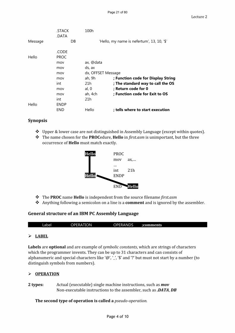
Lecture 2Assembler Overview Registers DiscussedIn this section will show you how to write, assemble, link and execute a program that displays your name on the screen.As we will be using a Command Prompt window and hence using virtual 8086 mode for all our programs, the naming convention for filenames must be of the 8.3 format. Anyway, even if MS Windows allow us 256-character long filenames, the trademark of a good programmer is still 8.3 format filenames.No blank space allowed in the filename. Use underscores (another trademark of an IT literate person!!!)The 3 types of files we will be working with are indicated by the following extensions:.ASM Assembly language source programs that you write..OBJ Object files; the output produced by the assembler from an input .ASM file..EXE Executable files produced by the linker utility combining one or more .OBJ files.
Editor (program) EDIT.COM or PWB
masm or tasm assembly program
Link or tlink linker program
;; FIRST.ASM – Our first Assembly Language Program. This program ;; displays the line “ Hello, my name is nefertum” on the screen
.MODELSMALL
.586 ; allows Pentium instructions. Must come after .MODEL
Page 3 of 10
EAX ah AX
EBX bh BX
ECX ch CX
EDX dh AX
ESI SI
EDI DI
EBP BP
CS
IPo d i t s z
c
SP
DS
ES
FS
GS
SS
The Programmer’
s Idea
Source (.ASM) File
Object (.OBJ) File
Executable (.EXE) File
Page 20 of 80
Lecture 2.STACK 100h.DATA
Message DB ‘Hello, my name is nefertum’, 13, 10, ‘$’
.CODEHello PROC
mov ax, @datamov ds, axmov dx, OFFSET Messagemov ah, 9h ; Function code for Display Stringint 21h ; The standard way to call the OSmov al, 0 ; Return code for 0mov ah, 4ch ; Function code for Exit to OSint 21h
Hello ENDPEND Hello ; tells where to start execution
Synopsis
Upper & lower case are not distinguished in Assembly Language (except within quotes). The name chosen for the PROCedure, Hello in first.asm is unimportant, but the three occurrence of Hello must match exactly.
Hello PROCmov ax,……int 21hHello ENDPEND Hello
The PROC name Hello is independent from the source filename first.asm Anything following a semicolon on a line is a comment and is ignored by the assembler.
General structure of an IBM PC Assembly Language
Label OPERATION OPERANDS ;comments
LABEL
Labels are optional and are example of symbolic constants, which are strings of characters which the programmer invents. They can be up to 31 characters and can consists of alphanumeric and special characters like ‘@’, ‘_’, ‘$’ and ‘?’ but must not start by a number (to distinguish symbols from numbers). OPERATION
2 types: Actual (executable) single machine instructions, such as movNon-executable instructions to the assembler, such as .DATA, DB
The second type of operation is called a pseudo-operation.
Page 4 of 10
Page 21 of 80
Lecture 2Both operations are specified using a symbolic code called the OPERATION CODE (OPCODE)Pseudo-operations are usually shown in upper case to distinguish them from executable machine instructions. OPERANDS Each op-code can have zero or more operands. Real machine instructions usually have one or two.Global Program Structure
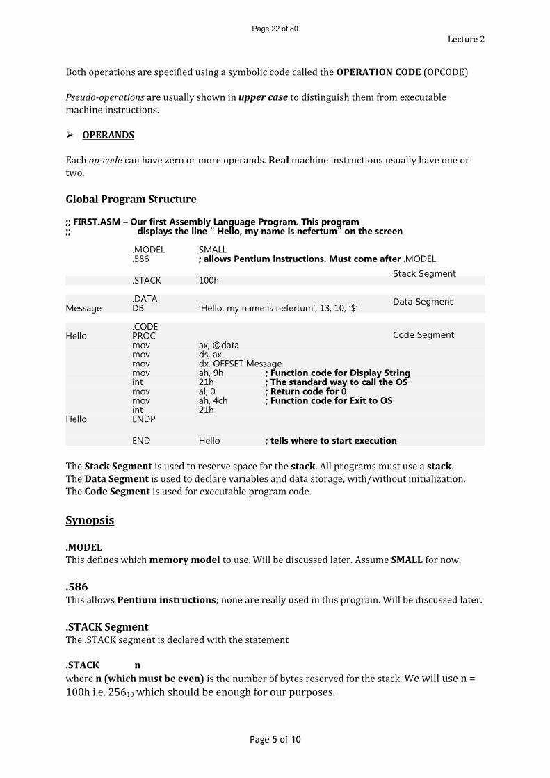
;; FIRST.ASM – Our first Assembly Language Program. This program ;; displays the line “ Hello, my name is nefertum” on the screen
.MODEL SMALL
.586 ; allows Pentium instructions. Must come after .MODEL
.STACK 100h
.DATAMessage DB ‘Hello, my name is nefertum’, 13, 10, ‘$’
.CODEHello PROC
mov ax, @datamov ds, axmov dx, OFFSET Messagemov ah, 9h ; Function code for Display Stringint 21h ; The standard way to call the OSmov al, 0 ; Return code for 0mov ah, 4ch ; Function code for Exit to OSint 21h
Hello ENDP
END Hello ; tells where to start executionThe Stack Segment is used to reserve space for the stack. All programs must use a stack.The Data Segment is used to declare variables and data storage, with/without initialization.The Code Segment is used for executable program code.Synopsis
.MODELThis defines which memory model to use. Will be discussed later. Assume SMALL for now.
.586This allows Pentium instructions; none are really used in this program. Will be discussed later.
.STACK SegmentThe .STACK segment is declared with the statement
.STACK n where n (which must be even) is the number of bytes reserved for the stack. We will use n = 100h i.e. 25610 which should be enough for our purposes.Page 5 of 10
Stack Segment
Data Segment
Code Segment
Page 22 of 80
Lecture 2.DATA SegmentThe .DATA segment is used to define variables, with or without initial values. In our first, program we have used:
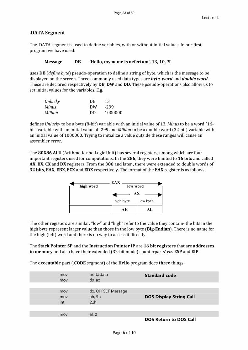
Message DB ‘Hello, my name is nefertum’, 13, 10, ‘$’uses DB (define byte) pseudo-operation to define a string of byte, which is the message to be displayed on the screen. Three commonly used data types are byte, word and double word. These are declared respectively by DB, DW and DD. These pseudo-operations also allow us to set initial values for the variables. E.g.Unlucky DB 13Minus DW -299Million DD 1000000defines Unlucky to be a byte (8-bit) variable with an initial value of 13, Minus to be a word (16-bit) variable with an initial value of -299 and Million to be a double word (32-bit) variable with an initial value of 1000000. Trying to initialize a value outside these ranges will cause an assembler error. The 80X86 ALU (Arithmetic and Logic Unit) has several registers, among which are four important registers used for computations. In the 286, they were limited to 16 bits and called
AX, BX, CX and DX registers. From the 386 and later , there were extended to double words of 32 bits, EAX, EBX, ECX and EDX respectively. The format of the EAX register is as follows:
The other registers are similar. “low” and “high” refer to the value they contain- the bits in the high byte represent larger value than those in the low byte (Big-Endian). There is no name for the high (left) word and there is no way to access it directly.The Stack Pointer SP and the Instruction Pointer IP are 16 bit registers that are addresses in memory and also have their extended (32-bit mode) counterparts’ viz. ESP and EIPThe executable part (.CODE segment) of the Hello program does three things: mov ax, @data
mov ds, ax
mov dx, OFFSET Messagemov ah, 9hint 21h
mov al, 0
Page 6 of 10
AH AL
EAX
AX
high byte low byte
low wordhigh word
Standard code
DOS Display String Call
DOS Return to DOS Call
Page 23 of 80
Lecture 2mov ah, 4chint 21hTwo instructions are used: the mov instruction which moves data from place to place and the
int 21h instruction which causes the operating system to perform various functions. Most 80X86 opcodes are written in three letters. The mov instructionSyntax: mov destination, source ;destination = sourcemov is really a copy instruction since the previous content of the source is unchanged. Thus if ax = 1234 and bx = 9876 and the instruction mov ax, bx is executed, we will have both ax and bx equal to 9876.There are various possibilities for the source and destination operands:
mov memory or register, memory or register or constantwhich is abbreviated as: mov mem / reg , mem / reg / constantNote: mov copies FROM right TO left-hand operand.GOLDEN RULES
1. You cannot move MEMORY to MEMORY directly2. You cannot move TO a CONSTANT3. You cannot move operands of DISSIMILAR SIZES
E.g.mov ax, A ;okmov A, ax ;okmov ax, bx ;okmov A, 345 ;okmov ax, 345 ;okmov A, B ;illegal – memory to memorymov 345, A ;illegal – can’t move TO constantmov ax, 24 ;okmov al, 24 ;okmov eax, 24 ;okmov al, 345 ;illegal – word to byte movemov ax, 100000 ;illegal – double to word movemov ax, al ;illegal – byte to word move
Page 7 of 10
Page 24 of 80
Lecture 2 The int 21h instructionOperating system functions on the IBM PC are called DOS calls, after the original operating system MS-DOS. Using DOS is much like using standard procedures like puts(), printf(), cout in C/C++.
DOS Call Syntax:; Load parameters to DOS Call into registersmov ah, function codeint 21h ;call DOS and returned values (if any) are in registersEach DOS call has its own function code number (in Hex) and pattern of registers used for sending and receiving values.
The DOS Display String CallThe DOS call with function code 9h is used to display a string of characters on the screen. The 9h function displays a string of ASCII characters whose address is in the dx register, up to but not including the first ‘$’ sign encountered. The form of the call is
mov dx, OFFSET Messagemov ah, 9hint 21hThe first mov instruction is used to load the address of the ASCII string into dx. The line in the data region:
Message DB “Hello, my name is nefertum”, 13, 10, “$”is used to define the string to be displayed. The numbers 13 and 10 are the ASCII values for Carriage Return and Line Feed, respectively. The Exit to DOS CallAn explicit return to the OS is needed because the computer will continue trying to execute whatever garbage lies in memory beyond the end of your program. To end execution of your program, you must execute the return to DOS call, which is:
mov al, 0h ; return codemov ah, 4ch ; Exit to DOS function codeint 21hThe two mov instructions could also have been written as a single instruction:mov ax, 4c00h
Page 8 of 10
Page 25 of 80
Lecture 2DOS call 4ch has one parameter, the return code in the ah register. The return code is traditionally zero for a normal return, nonzero for an error return. This call is analogous to the C/C++ exit() function and the return statement in the main() function that returns a value.Down Memory LaneA byte can contain any unsigned number from 0 to 255 or any signed number from -128 to 127 (signed numbers -128 to -1 corresponds to the unsigned numbers 128 to 255 in a byte)You can specify a sequence of values as such:
Abyte DB 12, 99, 20defines 3 consecutive variables with initial values 12, 99 and 20 respectively. Abyte is the name of the first variable whose value is 12. The byte containing 99 is an ‘anonymous’ variable which can be referred as [Abyte+1] and the variable containing value 20 as [Abyte+2]These 2 code fragments are equivalent:Abyte DB 12
DB 99DB 20Or
Abyte DB 12, 99DB 20
Uninitialized Variables
ByteVar DB ? ;ByteVar is a byte with NO initial value WordVar DW ? ;WordVar is a word with NO initial value
ASCII VariablesBytes containing the ASCII representation of characters can be defined by enclosing the characters in paired single (‘) or double (“) quotes:Hi DB ‘H’, ‘e’, ‘l’, ‘l’, ‘o’is equal toHi DB ‘Hello’orHi DB “Hello”
Non-printable CharactersFor non-printable characters, such as Carriage Return or Line Feed, (whose ASCII values are 13 and 10 respectively) the only way to get them with a DB instruction is to include them numerically:Message DB ‘Hello, my name is nefertum’, 13, 10, ‘$’
Page 9 of 10
Page 26 of 80
Lecture 2Creating ArraysData definitions can be repeated by using the DUP operation. E.g.
Ones DB 100 DUP (1)defines 100 consecutive bytes containing the number 1 (the first is called ‘Ones’)DB 10 DUP (2, 3, ?)defines 30 bytes which are consecutively 2, 3, ?, 2, 3, ?, …
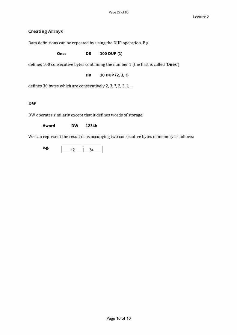
DWDW operates similarly except that it defines words of storage.Aword DW 1234hWe can represent the result of as occupying two consecutive bytes of memory as follows:e.g.
Page 10 of 10
12 34
Page 27 of 80
Lecture 3MACROS for I/OAs you have probably noticed, writing DOS calls can become tedious. Much of the code is repetitive, and each call has its own function code and register usage. You are probably used to dealing with complexity by making a repeated code a procedure or function.Assembly language allows you to use a single invented name to represent frequently used sequence of instructions. This name is used like an ordinary machine instruction, and is called a macro-instruction, or macro for short. Macro means ‘large’ and is intended to suggest grouping several instructions into a single large instruction. The group can contain ordinary machine operations, pseudo-operations, or even other macro instructions.When an assembler encounters the name of a macro, it replaces it with the sequence of instructions the macro consists of. The replacement process is called expanding the macro. This is analogous to the #define statement in C. We will make use of an inbuilt package of macros that is supplied by MASM called PCMAC.INC. Any source program that uses PCMAC.INC must contain the following line before using any of its macros:
INCLUDE PCMAC.INCThe statement above assumes that the PCMAC.INC file is in the current directory. The full path of the file can also be given:INCLUDE C:\MASM615\INCLUDE\PCMAC.INCThe simplest macro we will use is _Begin, which acts as a substitute for the standard code in the
FIRST.ASM program replacing:mov ax, @datamov ds, axTwo more complicated macros are _PutStr, which is the substitute for the DOS 9h call and _Exit which is the substitute for the DOS 4ch call. They are in the form:_PutStr label-of-‘$’ -terminated-stringand_Exit program-return-value
program-return-value is optional and if omitted, 0 will be used. The first letter is usually capitalized to distinguish them from machine instructions and pseudo-operations and all macros in PCMAC.INC starts with an underscore to distinguish them from user-created macros.Hence FIRST.ASM can be rewritten as:
;; FIRST.ASM – Our first Assembly Language Program. This program ;; displays the line “ Hello, my name is nefertum” on the screen
Page 1 of 7
Page 28 of 80
Lecture 3INCLUDE C:\MASM615\INCLUDE\PCMAC.INC
.MODELSMALL
.586 ; allows Pentium instructions. Must come after .MODEL
.STACK 100h
.DATAMessage DB ‘Hello, my name is Rishi Heerasing’, 13, 10, ‘$’
.CODEHello PROC
_Begin_PutStr Message_Exit 0 ;Return to DOS with (normal) return code 0
Hello ENDPEND Hello ; tells where to start execution
THE DOS DISPLAY CHARACTER CALLYou may be wondering how to display the “$” character, since _PutStr stops when it sees a ‘$’ and doesn’t display it. In fact there is NO WAY to display a “$” with _PutStr. (Recall Ex6Msg and Ex7Msg which print exactly the same thing, and neither prints the whole message. The easiest way to display a “$” is to use another DOS call, number 2h, which displays the single character it finds in register dl. This can be achieved by the following:mov dl, ‘$’ ;copy “$” in dlmov ah, 2h ;call the DOS functionint 21h ;Return to OSThe above code has a corresponding macro, _PutCh, the syntax is _PutCh ‘$’The _PutCh macro can be used to display one or more characters by listing them in the operand position. For instance, we could display a carriage return/line feed pair by coding,_PutCh 13, 10which generates two DOS 2h calls. (Note: _PutStr Message1, Message2 is not allowed)
MAGIC NUMBERSIt is usually poor programming practice to use magic numbers in a program. Magic numbers are constants (other than 0 and 1) that have some significance in the program. Some examples of magic numbers in our earlier programs were 10, 13, 9h and 4ch. It is better to give such numbers symbolic names. C does it using the #define statement but our assembler does it with EQU (short for EQUate) pseudo-op. We could therefore code the following:
Page 2 of 7
Page 29 of 80
Lecture 3CR EQU 13 ;equate CR to Carriage ReturnLF EQU 10 ;equate LF to Line FeedMessage DB ‘Hello, my name is nefertum’, CR, LF, ‘$’We can even set an equate for “$”:MsgEnd EQU ‘$’The codeA EQU Bis roughly equivalent to the C code#define A B e.g. #define PI 3.142
B can be replaced by an expression. ThusA EQU 10B EQU A + 1 ; is LEGAL: sets B to 11
Forward references are allowed:A EQU B + 1 ; is LEGAL: A eventually becomes 11B EQU 10But uses of A cannot occur before B is defined and circular equates are forbidden.Once a symbol has been defined with the EQU pseudo-op, it cannot be redefined.There are several advantages to using EQUates:
They make the program easier to read by documenting the meaning of constants. They make the program easier to change as changes needs to be effected in one place only. Different versions of a program can be specified by the values of one or more EQUates, set at the beginning of the program. The points above are even more important in programs where a single constant has two different meanings.As an example of the last point consider that the program also used the number 13 as an unlucky number and declared as follows:Unlucky EQU 13CR EQU 13Then if at some later stage, we decided to change the unlucky 13’s (but not Carriage Return 13’s); it would be easy to do so. NUMERIC I/OAs you have probably realised, programming I/O of numbers in Assembly turns out to be more difficult and cryptic than expected. That is why we use high level languages whenever we can.
Page 3 of 7
Page 30 of 80

Lecture 3Since reading and displaying numbers is done repeatedly, a library called UTIL.LIB will be used. This library contains sub-procedures to do numeric I/O and other useful things.We will look at six simple numeric I/O procedures present in that library: GetDec reads a decimal integer (with optional “-“sign) from the keyboard and returns with its value (as a
binary) in AX. GetDec reads characters until it encounters one that cannot belong to the number.
GetDDec is similar to GetDec but reads in a double word (32-bit) in EAX.PutDec displays the (binary) number in AX as a decimal number (with – sign if negative) at the cursor in
the Prompt Window.PutDDec is similar to PutDec but displays the number in EAX instead.PutHex displays the (binary) number in AX as a hexadecimal number at the cursor in the Prompt
Window (in exactly four characters, with no trailing ‘h’ or extra leading ‘0’).PutDHex is similar to PutHex but displays the number in EAX as exactly eight characters.A program that uses these procedures must include the EXTRN pseudo-operation line immediately after the .CODE pseudo-op:
Accessing Library Procedures
.CODEEXTRN GetDec : NEAR, PutDec : NEAR, etc…
ProcName PROC …
EXTRN stands for EXTeRNal, indicating that these procedures are defined elsewhere. The EXTRN procedure only needs to list the procedures you are actually using. NEAR will be discussed later.The difference between EXTRN and INCLUDE is as follows: INCLUDE causes the assembler to insert a file of source text into the program while assembling it. EXTRN tells the assembler that the linker will find an already assembled PROC of this name in another of the object files it is told to link.All of the following procedures are executed by using the call instruction. To display a number at the cursor position in the Prompt Window:Displaying Numbers;Display a number in decimal
mov ax, number-to-be-displayedcall putDec ;display number in decimal;Display a LARGE number in decimalmov eax, number-to-be-displayedcall putDDec ;display number in decimal;Display a number in hexadecimalmov ax, number-to-be-displayedcall putHex ;display number in hexadecimal;Display a LARGE number in hexadecimalmov eax, number-to-be-displayedcall putDHex ;display number in decimal
Page 4 of 7
Page 31 of 80
Lecture 3Inputting NumbersTo input a decimal number from the Keyboard:
call GetDec ;Typed number is now in ax (in binary)call GetDDec ;Typed number is now in eax (in binary)Note that GetDec doesn’t display any prompt, so you probably have to use _PutStr to inform the user that the program is waiting for an input. A possible snippet might be:FirstNumber DW ?Prompt DB ‘Type in first integer: $’ ; Note: No CR-LF
…_PutStr Promptcall GetDecmov FirstNumber, axSince the CR-LF is omitted in Prompt, the typed input will be beside the prompt. For example (user typing showed in bold):Type in first integer: 1234 ↵The hex equivalent is: 04D2HAssembling the program using GetDec, PutDec, etc… is same as before, but when you are linking the program, the linker must be told where to find these procedures. The appropriate command is
link or tlink MyProgfilename , , ,util;Note: Exactly three commas are needed. The two other parameters mean that default value will be used. If util is used on its own it is implied that the file UTIL.LIB is in the current directory. If for instance, it is in the directory c:\masm615, then you will have to enter:
link or tlink MyProgfilename, , ,c:\masm615\util;With masm you can assemble and link in one step:ml MyProgfilename.asm util.libNotice that the extensions .asm and .lib are essential to tell ml what to do with the various files. If
util.lib is not in the current directory, its actual directory must be specified. Note that the ml command does not have commas.
Example Program: DecToHex.asmWrite an assembly language program DecToHex that reads in a decimal number from the keyboard and displays its representation in hex.Page 5 of 7
Page 32 of 80

Lecture 3The .CODE part for a straightforward program to do the conversion could be:
.CODEEXTRN GetDec : NEAR, PutHex : NEAR
Dec2Hex PROC_Begincall GetDec ;ax = decimal number from keyboardcall PutHex ;display contents of ax in hex_Exit 0 ;return to DOS
Dec2Hex ENDPEND Dec2HexThis program will work but it is not user-friendly. It should really contain a prompt telling the user what to enter and a message describing the output.But if we write:
Prompt DB ‘Enter decimal number: $’Message DB ‘The hex equivalent is: $’
…_PutStr Promptcall GetDec_PutStr Message WRONG!!!call PutHexThe hex value will be garbage. Why?The reason is that _PutStr destroys ah, and thus ax as well.
Solution: We need to save ax before the second _PutStr call and restore it after. The easiest way to save and restore a register is to set up a word (16-bit) variable in which to save it.Prompt DB ‘Enter decimal number: $’Message DB ‘The hex equivalent is: $’SaveAX DW ?
…_PutStr Promptcall GetDecmov SaveAX, ax ;;save ax in variable SaveAX
_PutStr Messagemov ax, SaveAX ;;Restore value of ax from SaveAX
call PutHex
Note: We could have used another register instead of SaveAX, say bx or cx but not dx. We have to be sure that the registers will be unaltered by DOS calls.
To be on the safe side, store data in variables instead of registers; unless that you are sure that the registers’ data will not be changed.The complete program is below. A trailing ‘H’ has been added as putHex does not add it.
Page 6 of 7
Page 33 of 80

Lecture 3;; DecToHex.asm – input of a decimal number from keyboard and displays its hex equivalent
INCLUDE PCMAC.INC.MODELSMALL.586.STACK 100h
.DATAPrompt DB ‘Enter decimal number: $’Message DB ‘The hex equivalent is: $’SaveAX DW ?
.CODEEXTRN GetDec : NEAR, PutHex : NEAR
Dec2Hex PROC_Begin_PutStr Promptcall GetDecmov SaveAX, ax_PutStr Messagemov ax, SaveAXcall PutHex_PutCh ‘H’, 13, 10 ;Display trailing ‘H’ for hex and CR-LF
_Exit 0 ;return to DOSDec2Hex ENDP
END Dec2Hex
Page 7 of 7
Page 34 of 80
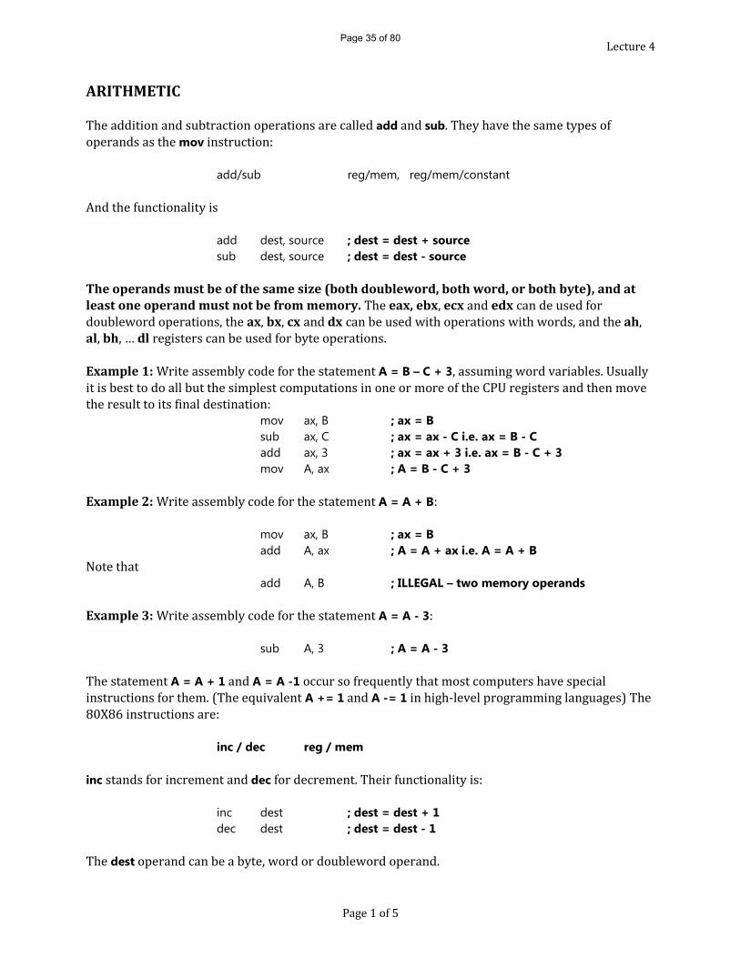
Lecture 4ARITHMETICThe addition and subtraction operations are called add and sub. They have the same types of operands as the mov instruction:
add/sub reg/mem, reg/mem/constantAnd the functionality isadd dest, source ; dest = dest + sourcesub dest, source ; dest = dest - source
The operands must be of the same size (both doubleword, both word, or both byte), and at least one operand must not be from memory. The eax, ebx, ecx and edx can de used for doubleword operations, the ax, bx, cx and dx can be used with operations with words, and the ah, al, bh, … dl registers can be used for byte operations.Example 1: Write assembly code for the statement A = B – C + 3, assuming word variables. Usually it is best to do all but the simplest computations in one or more of the CPU registers and then move the result to its final destination:
mov ax, B ; ax = Bsub ax, C ; ax = ax - C i.e. ax = B - Cadd ax, 3 ; ax = ax + 3 i.e. ax = B - C + 3mov A, ax ; A = B - C + 3
Example 2: Write assembly code for the statement A = A + B:mov ax, B ; ax = Badd A, ax ; A = A + ax i.e. A = A + BNote thatadd A, B ; ILLEGAL – two memory operands
Example 3: Write assembly code for the statement A = A - 3:sub A, 3 ; A = A - 3The statement A = A + 1 and A = A -1 occur so frequently that most computers have special instructions for them. (The equivalent A += 1 and A -= 1 in high-level programming languages) The 80X86 instructions are:
inc / dec reg / mem
inc stands for increment and dec for decrement. Their functionality is:inc dest ; dest = dest + 1dec dest ; dest = dest - 1The dest operand can be a byte, word or doubleword operand.
Page 1 of 5
Page 35 of 80

Lecture 4There is another instruction in the mould of inc/dec that is often useful:
neg reg / memwhich negates its byte, word or doubleword operand:neg dest ; dest = - dest
Example 4: Suppose that Char is a byte variable containing a lowercase letter. Write assembly language to convert it to the corresponding uppercase letter.We use the fact that upper-case-letter + ‘a’ – ‘A’ = corresponding lower-case-letterfor example, that ‘h’ = ‘H’ + ‘a’ – ‘A’. Then, the code will besub Char, ‘a’ – ‘A’
MULTIPLICATION AND DIVISIONMultiplication and division are always much complex in computers than addition and subtraction. It’s obvious why they must be: multiplying two n-digit numbers will in general produce a 2n-digit number, and to make division an inverse operation, we should be able to divide a 2n digit number by an n-digit number. Also we want to be able to produce the remainder as well as the quotient on division. Also the problem of positive and negative numbers must be dealt with 2’s complement doesn’t work. For instance, multiplication by -3 and by its 2’s complement representation 0FFFDh, considered as an unsigned number (65,533) are two different operations. As a result, it has different operations – mul and div for unsigned numbers and imul and idiv for signed numbers.For multiplication, owing the fact that the product is twice as long as the numbers being multiplied, a special set of registers is used:Operand Size Multiplicand Multiplier ProductBYTE AL REGISTER ORMEMORY AXWORD AX AX(LOW) and DX(HIGH)DWORD EAX EAX(LOW) and EDX(HIGH)The instructions aremul reg/mem ;unsigned multiplyimul reg/mem ;signed (integer) multiply;only the multiplier is specified explicitly. The other operand and the product are specified by the table above using the size of reg/mem
Page 2 of 5
Page 36 of 80

Lecture 4If we want to multiply two words and get a word result; as we saw earlier, if a 32-bit signed or unsigned number actually fits in 16 bits, we just have to use the lower-order 16 bits (ax here). Thus we could code the statement A = B * C (A, B and C are signed word variables) by writing
mov ax, Bimul C ;ax is not written, it is assumedmov A, ax ;dx ignored, better be sure it can be!If the product is small enough, the high order bits in dx will be all sign bits, or in the case of unsigned multiplication, all zeroes.Notice that a constant multiplier is not allowed. This can be handled by moving the constant to a register and then multiplying. For instance:mov bx, constantimul bx ;multiplicand is ax, Result is dx/axTo avoid this inconvenience, the 80386 and up has added a workaround:imul reg1, re2/mem, const ;reg1=reg2/mem * constantandimul reg1, reg2/mem/const ;reg1 = reg1 * reg2/mem/constantThe first two operands must be of the same size – word or double word – and the product is the same size as the operands. There is no version for unsigned multiplication by constant, and
there is no version for any kind of division by constants. To make division the inverse of multiplication, the register (pair) containing the number to be divided is twice as long as the divisor ant the result. Also, division has two results, the quotient and the remainder.Operand Size Dividend Divisor Quotient RemainderBYTE AX REGISTER ORMEMORY AL AHWORD AX and DX AX DXDWORD EAX and EDX EAX EDXThe instructions arediv reg/mem ;unsigned multiplyidiv reg/mem ;signed (integer) multiplyonly the divisor is specified explicitly. The dividend and the result are specified by the table above using the size of reg/memWe have a problem if we want to divide a word by a word. We need some way of extending the word to double word in dx and ax. Similar problems arise when dividing by bytes and double words. The 80X86 comes to the rescue with instructions to do the extension for signed numbers: In the word case, we would normally have a 16-bit number that we wish to divide by another 16-bit number. In the computer, we need to convert the dividend (=numerator) into a 32-bit number. That’s easy enough in the case of unsigned numbers- just add 16 zero bits to the left. In case of
Page 3 of 5
Page 37 of 80
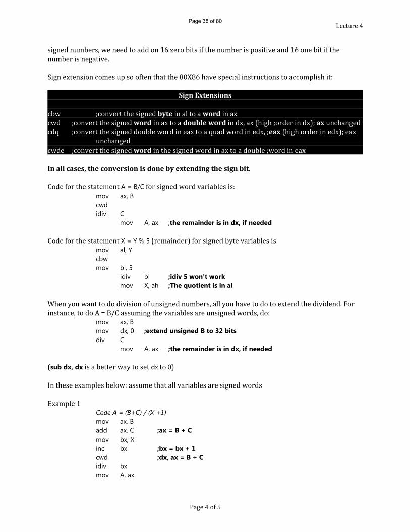
Lecture 4signed numbers, we need to add on 16 zero bits if the number is positive and 16 one bit if the number is negative. Sign extension comes up so often that the 80X86 have special instructions to accomplish it:
Sign Extensionscbw ;convert the signed byte in al to a word in axcwd ;convert the signed word in ax to a double word in dx, ax (high ;order in dx); ax unchangedcdq ;convert the signed double word in eax to a quad word in edx, ;eax (high order in edx); eax unchangedcwde ;convert the signed word in the signed word in ax to a double ;word in eaxIn all cases, the conversion is done by extending the sign bit.Code for the statement A = B/C for signed word variables is:
mov ax, Bcwdidiv C
mov A, ax ;the remainder is in dx, if neededCode for the statement X = Y % 5 (remainder) for signed byte variables ismov al, Ycbwmov bl, 5
idiv bl ;idiv 5 won’t workmov X, ah ;The quotient is in alWhen you want to do division of unsigned numbers, all you have to do to extend the dividend. For instance, to do A = B/C assuming the variables are unsigned words, do:
mov ax, Bmov dx, 0 ;extend unsigned B to 32 bitsdiv C
mov A, ax ;the remainder is in dx, if needed(sub dx, dx is a better way to set dx to 0)In these examples below: assume that all variables are signed wordsExample 1 Code A = (B+C) / (X +1)mov ax, Badd ax, C ;ax = B + Cmov bx, Xinc bx ;bx = bx + 1cwd ;dx, ax = B + Cidiv bxmov A, ax
Page 4 of 5
Page 38 of 80

Lecture 4Example 2
Code A = 3 * C – 14 *Bmov ax, 3imul Cmov bx, ax ;save 3 * C temporarily in bxinc bx ;bx = bx + 1cwd ;dx, ax = B + Cidiv bxmov A, axExample 3Code A = (B/C) * (D+1). First compute B * (D+1), which will be the product in dx and ax and then divide by C.
mov ax, Dinc aximul Bidiv Cmov A, ax
Page 5 of 5
Page 39 of 80

Lecture 5COMPARING AND BRANCHINGComputer programs are of no particular worth unless decisions can be made in them. In IBM PC assembly Language (and most modern computers) decision-making is a two step process:1. Two numbers are compared using cmp, the compare instruction, which sets several bits in a 16-bit register of the CPU called the flags register, and 2. A conditional jump instruction is executed which does or does not go to a new location based on the values of those flags.The cmp instruction has two operands just like the mov instruction:
cmp reg/mem, reg/mem/constantwith the usual limitation of at most one memory operand per instruction. The operands can either be bytes, words or double words but as usual must be of the same size.The instruction
cmp op1, op2performs the subtraction op1 – op2, sets the flags according to the result, and discards the result. The flags set by the cmp instruction are as follows:O – Overflow Flag (OF), S – Sign Flag (SF), Z – Zero Flag (ZF), C – Carry Flag (CF)(The S flag is set to the sign of the result, the Z flag is set to 1 if the result is zero, and the O and C flags are set to the Overflow and Carry status of the result respectively. The shaded portion of the flags register represents other flags and unused bits.) For each of these flags there are two conditional jumps. For instance, jc jumps if the Carry flag is set i.e. is equal to 1, and jnc jumps on no carry flag, i.e. CF = 0. The >, <=, etc, conditions require complicated combinations of these jumps. So a number of other conditional jumps are provided:For SIGNED Numbers, after cmp op1, op2
je address ;jump if equal (op1 = op2)jne address ;jump if not equal (op1 ≠ op2)jg address ;jump if greater (op1 > op2)jge address ;jump if greater or equal (op1 ≥ op2)jl address ;jump if less (op1 < op2)jle address ;jump if less or equal (op1 ≤ op2)You can think of the relation in the conditional jump instruction as sitting between the operands.
cmp op1, op2 jl address
Page 1 of 5
EAX ah AX al
EBX bh BX bl
ECX ch CX cl
EDX dh AX dl
ESI SI
EDI DI
EBP BP
CS
IPo d i t s z
c
SP
DS
ES
FS
GS
SS
O S Z C
121315 14 1O11 679 8 45 013 2Bit number:
<
Page 40 of 80
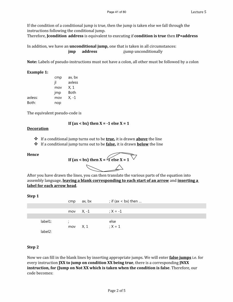
Lecture 5If the condition of a conditional jump is true, then the jump is taken else we fall through the instructions following the conditional jump.Therefore, Jcondition address is equivalent to executing if condition is true then IP=address In addition, we have an unconditional jump, one that is taken in all circumstances:
jmp address ;jump unconditionallyNote: Labels of pseudo-instructions must not have a colon, all other must be followed by a colonExample 1:
cmp ax, bxjl axlessmov X, 1jmp Both
axless: mov X, -1Both: nopThe equivalent pseudo-code is
If (ax < bx) then X = -1 else X = 1 Decoration
If a conditional jump turns out to be true, it is drawn above the line If a conditional jump turns out to be false, it is drawn below the line
HenceIf (ax < bx) then X = -1 else X = 1
After you have drawn the lines, you can then translate the various parts of the equation into assembly language, leaving a blank corresponding to each start of an arrow and inserting a label for each arrow head.Step 1
cmp ax, bx ; if (ax < bx) then …
mov X, -1 ; X = -1
label1: ; elsemov X, 1 ; X = 1
label2:
Step 2Now we can fill in the blank lines by inserting appropriate jumps. We will enter false jumps i.e. for every instruction JXX to jump on condition XX being true, there is a corresponding JNXX instruction, for (Jump on Not XX which is taken when the condition is false. Therefore, our code becomes:
Page 2 of 5
Page 41 of 80
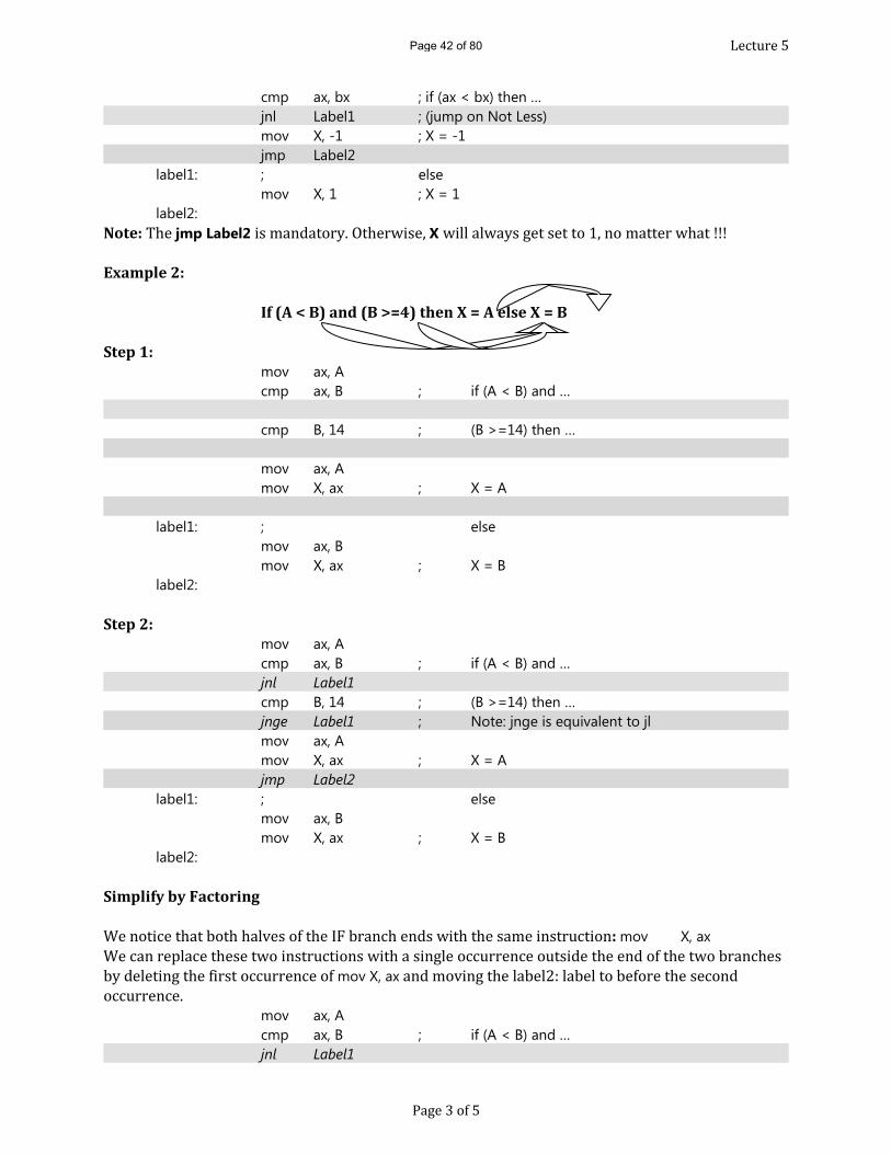
Lecture 5cmp ax, bx ; if (ax < bx) then …jnl Label1 ; (jump on Not Less)mov X, -1 ; X = -1jmp Label2
label1: ; elsemov X, 1 ; X = 1
label2:Note: The jmp Label2 is mandatory. Otherwise, X will always get set to 1, no matter what !!! Example 2:
If (A < B) and (B >=4) then X = A else X = B
Step 1:mov ax, Acmp ax, B ; if (A < B) and …
cmp B, 14 ; (B >=14) then …
mov ax, Amov X, ax ; X = A
label1: ; elsemov ax, Bmov X, ax ; X = B
label2:
Step 2:mov ax, Acmp ax, B ; if (A < B) and …jnl Label1cmp B, 14 ; (B >=14) then …jnge Label1 ; Note: jnge is equivalent to jlmov ax, Amov X, ax ; X = Ajmp Label2
label1: ; elsemov ax, Bmov X, ax ; X = B
label2:
Simplify by FactoringWe notice that both halves of the IF branch ends with the same instruction: mov X, axWe can replace these two instructions with a single occurrence outside the end of the two branches by deleting the first occurrence of mov X, ax and moving the label2: label to before the second occurrence.mov ax, Acmp ax, B ; if (A < B) and …jnl Label1
Page 3 of 5
Page 42 of 80
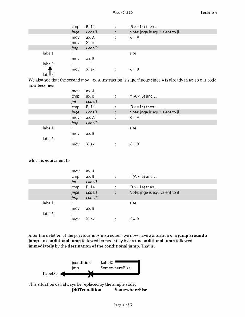
Lecture 5cmp B, 14 ; (B >=14) then …jnge Label1 ; Note: jnge is equivalent to jlmov ax, A ; X = Amov X, axjmp Label2
label1: ; elsemov ax, B
label2: ;mov X, ax ; X = B
label2:We also see that the second mov ax, A instruction is superfluous since A is already in ax, so our code now becomes:mov ax, Acmp ax, B ; if (A < B) and …jnl Label1cmp B, 14 ; (B >=14) then …jnge Label1 ; Note: jnge is equivalent to jlmov ax, A ; X = Ajmp Label2
label1: ; elsemov ax, B
label2: ;mov X, ax ; X = B
which is equivalent tomov ax, Acmp ax, B ; if (A < B) and …jnl Label1cmp B, 14 ; (B >=14) then …jnge Label1 ; Note: jnge is equivalent to jljmp Label2
label1: ; elsemov ax, B
label2: ;mov X, ax ; X = B
After the deletion of the previous mov instruction, we now have a situation of a jump around a jump – a conditional jump followed immediately by an unconditional jump followed immediately by the destination of the conditional jump. That is:
jcondition LabelXjmp SomewhereElseLabelX:This situation can always be replaced by the simple code:jNOTcondition SomewhereElse
Page 4 of 5
Page 43 of 80

Lecture 5Final code becomes:
mov ax, Acmp ax, B ; if (A < B) and …jnl Label1cmp B, 14 ; (B >=14) then …jge Label2 ; X = A
label1: ; elsemov ax, B ; X = B
label2: ;mov X, ax
UNSIGNED CONDITIONAL JUMPSIt is sometimes necessary to use unsigned conditional jumps. Subtraction is the same whether the numbers are signed or not. The necessary instructions are:For UNSIGNED Numbers, after cmp op1, op2
ja address ;jump if above (op1 = op2)jae address ;jump if above or equal (op1 ≥ op2)jb address ;jump if below (op1 < op2)jbe address ;jump if below or equal (op1 ≤ op2)
ALWAYS USE AN UNSIGNED JUMP WHEN COMPARING ADDRESSES. Why?When we compare addresses, we think of the larger address occurring after the smaller one in memory.e.g. 1111h < 2222h of course, but what about comparing 7777h and 8888h?If we use a signed jump, we will get 7777h > 8888h because 8888h is negative!If we use an unsigned jump, we will get 8888h > 7777h as we had expected.
Page 5 of 5
Page 44 of 80

Lecture 6SUBPROGRAMS AND STACK
SUBPROGRAMSHigher level languages use subprograms all the time. Some languages have two types of subprograms: procedures (or subroutines) and functions, while others, like C, only have functions. Normally, the difference between the two is that functions return a value (only one!). Assembly languages uses "functions" called "PROC"s and typically returns a value in AX register. In C, we evoke functions by using the name with parentheses. In assembly language we put the instruction:call SubProg
Rules
• Subprograms can be included in the same file or stored in a separate file. • If they are in the same file, the ordering and naming is immaterial. • There is no main(). The first PROC to be run is the one specified by END pseudo-op. • Only the first PROC to execute the code to initialize the data segment register:
mov ax, @data mov ds, ax
• For readability, put the .DATA before the .CODE for the subprogram: ...
Main ENDP .DATA ... data for subprog ... .CODE
SubProg PROC Code for subprog
• Unless labels are defined inside a PROC as PUBLIC, they are local to PROC that defined them. THE HARDWARE STACKThe hardware stack and stack pointer sp are necessary to get subprograms to work properly. Actually early CPUs did not have them, and as a result, they were more limited than what we have today. For instance, recursion was not possible. A stack is a data structure where data can only be added or removed at one end, so it is Last-In, First-Out (LIFO). There are special instructions built into the CPU to work with the stack.
Page 1 of 5
Page 45 of 80
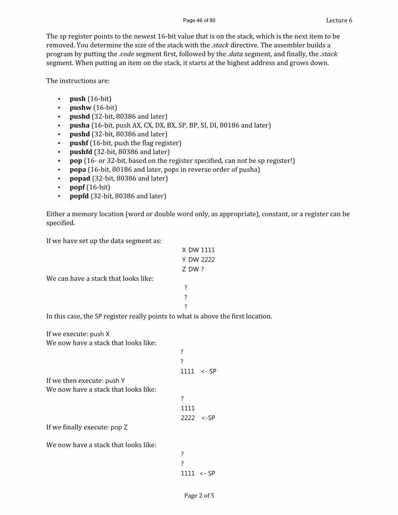
Lecture 6The sp register points to the newest 16-bit value that is on the stack, which is the next item to be removed. You determine the size of the stack with the .stack directive. The assembler builds a program by putting the .code segment first, followed by the .data segment, and finally, the .stack segment. When putting an item on the stack, it starts at the highest address and grows down. The instructions are: • push (16-bit) • pushw (16-bit) • pushd (32-bit, 80386 and later) • pusha (16-bit, push AX, CX, DX, BX, SP, BP, SI, DI, 80186 and later) • pushd (32-bit, 80386 and later) • pushf (16-bit, push the flag register) • pushfd (32-bit, 80386 and later) • pop (16- or 32-bit, based on the register specified, can not be sp register!) • popa (16-bit, 80186 and later, pops in reverse order of pusha) • popad (32-bit, 80386 and later) • popf (16-bit) • popfd (32-bit, 80386 and later) Either a memory location (word or double word only, as appropriate), constant, or a register can be specified. If we have set up the data segment as:
X DW 1111Y DW 2222Z DW ? We can have a stack that looks like: ? ? ? In this case, the SP register really points to what is above the first location. If we execute: push XWe now have a stack that looks like:
?? 1111 <- SPIf we then execute: push YWe now have a stack that looks like: ? 1111 2222 <-SPIf we finally execute: pop ZWe now have a stack that looks like: ? ? 1111 <- SP
Page 2 of 5
Page 46 of 80

Lecture 6The location for the variable Z is set to 2222 and the SP register points to the previous entry. Note that stack location holding 2222 is considered unused and will be overwritten by the next push instruction. You can not count on items popped from the stack remaining in unused stack memory because the operating system also uses the stack. The hardware stack is implemented as a normal block of memory of the size you specified in the .STACK pseudo-op. If you do push X followed by pop X, nothing is changed. Saving and restoring registers is particularly important when using subprograms. You have the responsibility to save and restore important data in the registers before you call a subprogram and then you are responsible for restoring those registers afterwards. Subprograms should save and restore any registers that they use, unless they are returning values in certain registers! This means you have to write the instructions to do it! Subprograms should pop all items and only those items that they push on the stack!
CALL & RET
call and ret use the stack and the IP register. Remember the IP register always hold the address of the next instruction to be executed. The call instruction pushes the IP register contents onto the stack and then puts the address from the call instruction into the IP register. Since that is the end of the call instruction, the computer then gets the first instruction from the subprogram and executes it. When the ret is reached (and it should be there!!! You have to put it there!), the contents of the last item pushed on the stack is put into the IP register and the SP register is adjusted to point to the next newest value. Since normally, what is copied into the IP register is the address of the instruction after the call that we were just discussing, the program continues from that point. One of the most ingenious temporary uses of the stack is to call other subprogram. In fact a subprogram can call itself recursively, arbitrarily many times. The only thing to remember is the rule that a subprogram must pop off everything (and only those things) that it put onto the stack. That way, the return address will be available in the right position when the ret instruction is executed. When a subprogram is called within a subprogram, the call and corresponding ret take care to keeping the stack tidy automatically. Continuing this ingenious use, the sub procedure can use the stack for its local variables. Remember in C, the variables declared in the body of the function exist only while the function is being executed. When the control passes back to the caller, the local functions disappear. What happens is that the local variables are created on the stack below the return address (we must store in a register what the starting address of the local variables is) and then we can refer to the local variables as an offset from that start. This way when we have recursion, each instance of the function can only see its version of the local variables! We will get to see this better when we talk about addressing mode and arrays.
Page 3 of 5
Page 47 of 80
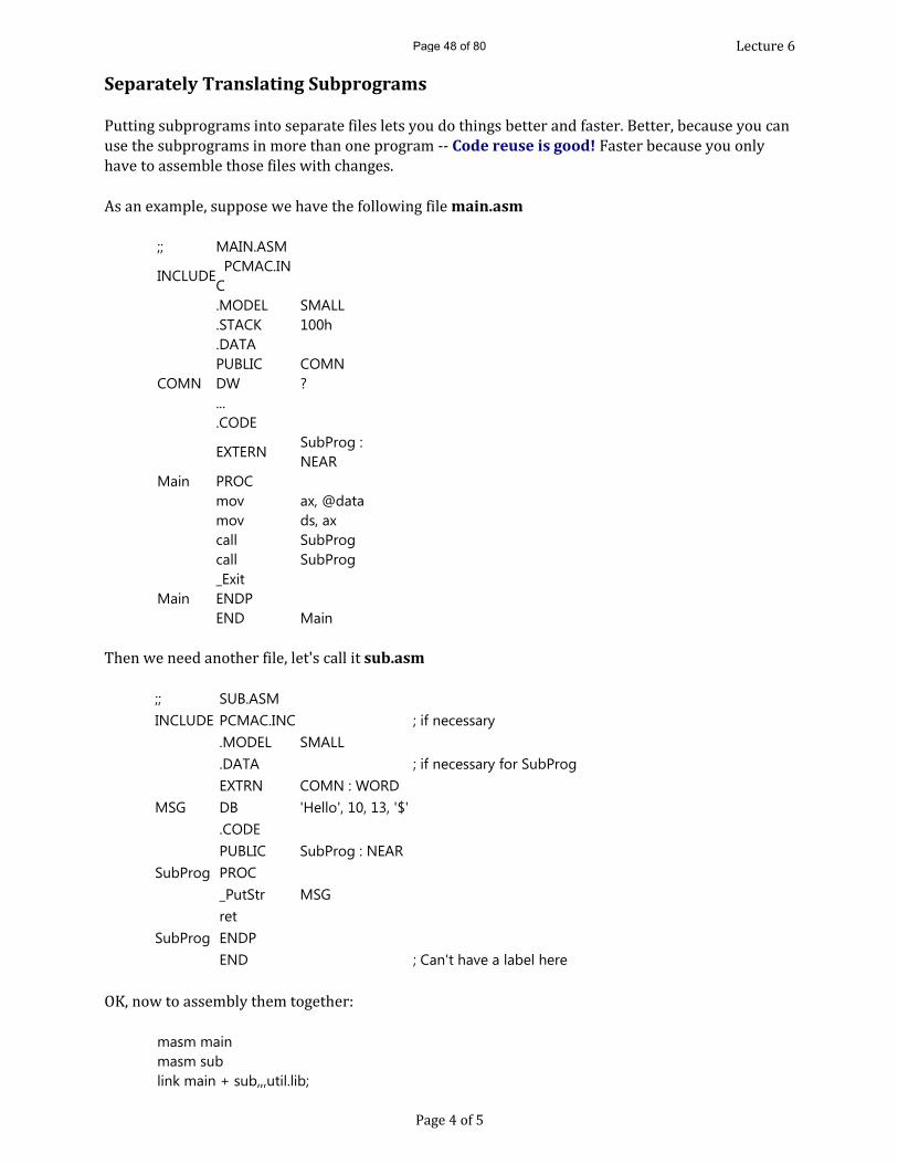
Lecture 6Separately Translating Subprograms Putting subprograms into separate files lets you do things better and faster. Better, because you can use the subprograms in more than one program -- Code reuse is good! Faster because you only have to assemble those files with changes. As an example, suppose we have the following file main.asm
;; MAIN.ASM
INCLUDE PCMAC.INC .MODEL SMALL .STACK 100h .DATA PUBLIC COMN
COMN DW ? ... .CODE
EXTERN SubProg : NEAR
Main PROC mov ax, @data mov ds, ax call SubProg call SubProg _Exit
Main ENDP END Main Then we need another file, let's call it sub.asm
;; SUB.ASM INCLUDE PCMAC.INC ; if necessary
.MODEL SMALL
.DATA ; if necessary for SubProgEXTRN COMN : WORD
MSG DB 'Hello', 10, 13, '$' .CODE PUBLIC SubProg : NEAR
SubProg PROC _PutStr MSG ret
SubProg ENDP END ; Can't have a label here OK, now to assembly them together:
masm mainmasm sublink main + sub,,,util.lib; Page 4 of 5
Page 48 of 80
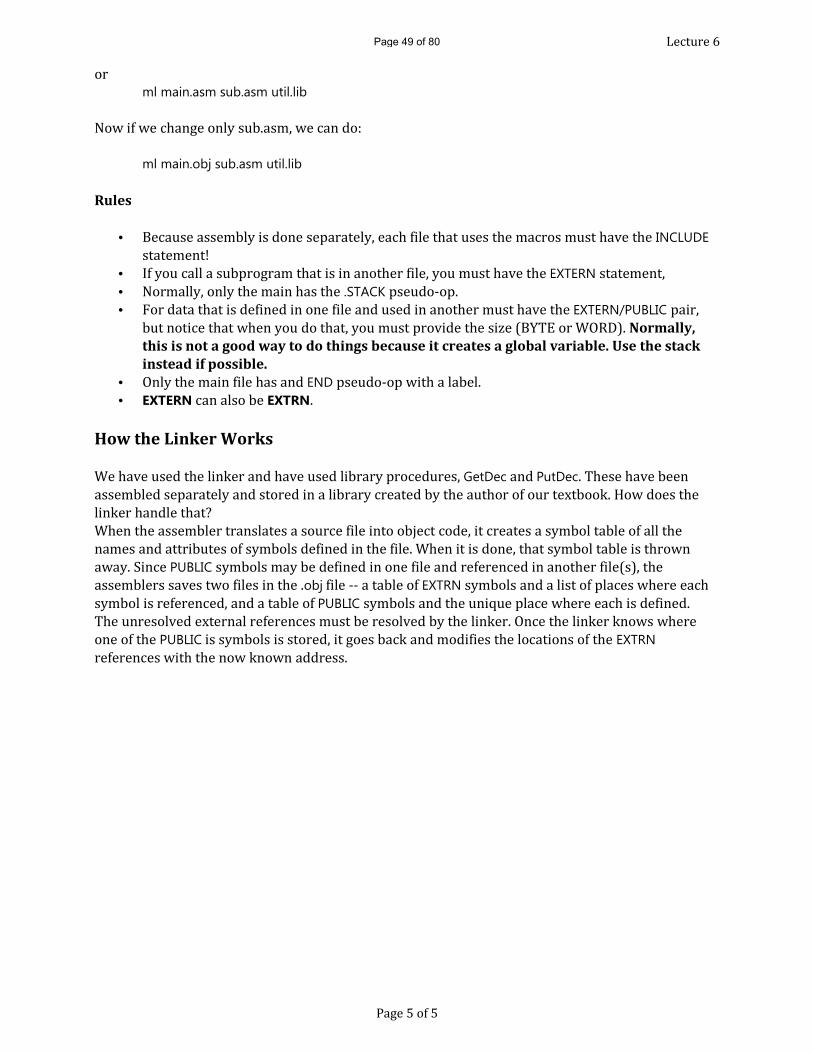
Lecture 6or ml main.asm sub.asm util.lib Now if we change only sub.asm, we can do: ml main.obj sub.asm util.lib
Rules
• Because assembly is done separately, each file that uses the macros must have the INCLUDE statement! • If you call a subprogram that is in another file, you must have the EXTERN statement, • Normally, only the main has the .STACK pseudo-op. • For data that is defined in one file and used in another must have the EXTERN/PUBLIC pair, but notice that when you do that, you must provide the size (BYTE or WORD). Normally,
this is not a good way to do things because it creates a global variable. Use the stack instead if possible.
• Only the main file has and END pseudo-op with a label. • EXTERN can also be EXTRN.
How the Linker Works We have used the linker and have used library procedures, GetDec and PutDec. These have been assembled separately and stored in a library created by the author of our textbook. How does the linker handle that? When the assembler translates a source file into object code, it creates a symbol table of all the names and attributes of symbols defined in the file. When it is done, that symbol table is thrown away. Since PUBLIC symbols may be defined in one file and referenced in another file(s), the assemblers saves two files in the .obj file -- a table of EXTRN symbols and a list of places where each symbol is referenced, and a table of PUBLIC symbols and the unique place where each is defined. The unresolved external references must be resolved by the linker. Once the linker knows where one of the PUBLIC is symbols is stored, it goes back and modifies the locations of the EXTRN references with the now known address.
Page 5 of 5
Page 49 of 80

Lecture 7MACRO AND PROGRAM TESTING
Every macro has a single macro declaration, and zero or more macro invocations. The invocations must occur physically after the declaration. (The file PCMAC.INC is essentially just a list of macro declarations.)Macro Declarations
MacroName MACRO Macro Parameter List….Prototype of the macro….ENDM
The prototype of the macro is a sequence of ‘real’ machine instructions (or other macro invocations) which will replace every invocation of MacroName.A simple form of _PutStr macro could be declared as follows:
_PutStr MACRO aStringmov dx, OFFSET aStringmov ah, 09hint 21hENDM
A macro invocation has the form:MacroName Actual Parameters to the macroEach time the assembler finds a macro invocation; it replaces the formal arguments with the actual parameters and then deletes the macro invocation and replaces it with the new version and replaces it with the new version of macro body.
Example Invocation
_PutStr myMessage
Example after Macro Expansion
mov dx, OFFSET myMessage
mov ah, 09h int 21h This example does not save us a lot of work, but we don't have to worry about remembering what it takes (registers, codes, etc) to make it work. It is easier to remember _PutStr and the label we wish to display.
Page 1 of 4
Page 50 of 80

Lecture 7Macro ExpansionThis macro is a "safe" macro, because it saves and restores affected registers. This is good sometimes, but it will always add the overhead of a push/pop pair. AddUp MACRO A, B, Sum
push axmov ax, Aadd ax, Bmov SUM, axpop axENDMNow to invoke it:AddUp 3, bx, Total This will become: push ax mov ax, 3 add ax, bx mov Total, ax pop ax Notice that in this invocation, we used a constant, a memory location, and a register. The sum gets stored in the memory location with the label Total. Additionally, the actual parameters are separated by commas, blanks, and tabs. If a macro invocation has more arguments than the declaration, the extra arguments are ignored. If it has fewer arguments, the extra parameters in the declaration are set to the empty string. That is what happens in our version of _PutStr, there is one more parameter than we have used.
Parameters ParenthesesSince blanks, tabs, and commas act as parameter separators, they must be handled differently when we want to embed them in an argument. Suppose we have the macro: DecBytes MACRO A, B, Symbol Symbol DB A DUP (B)
ENDM If we invoke it with: DecBytes 5 DUP (3) We have actually have arguments of "5", "DUP", and "(3)". We end up with:
(3) DB 5 DUP (DUP)
Page 2 of 4
Page 51 of 80
Lecture 7However, if we invoke it with: DecBytes 100, <5 DUP (3)>
We end up with: DB 100 DUP (5 DUP 3) Make sure you remember that blanks are separators!
10 dup(5) is two parameters 10 dup (5) is three parameters 10 dup ( 5 ) is five parameters Surround complicated macro parameters with <> parentheses Whenever a macro parameter is passed as a parameter to an inner macro, it should be enclosed in <> parentheses. Macros are more dangerous than subprograms, because some register usage is not obvious. When in doubt, save and restore the registers. A safe version is: bMac MACRO aPar
aMac <aPar> ENDM
Local SymbolsWhen a label is defined inside a macro, each time the macro expanded, the same label is reused. This is an error condition. The way to avoid that is to use local symbols. Max MACRO A, B
LOCAL noChange mov ax, A cmp ax, B jge noChange mov ax, B
noChange: ENDM
Assembly Listings To see the actual code produced by the macros, you can look at the assembly listing with the command: masm afile,,afile; or ml /Fl afile.asm
Page 3 of 4
Page 52 of 80

Lecture 7Pseudo-Macros for Repetition There are three pseudo-macros which expand a prototype repeatedly:
Pseudo-Macro Meaning REPT n REPeaT n times IRP Indefinite RePeat IRPC Indefinite RePeat CharactersThe simplest of these is the pseudo-macro REPT which merely repeats the prototype n times. Without any parameters, we could have a macro: REPT 20 DB 5, 3, ?, 18, 18 ENDM This is the equivalent of: DB 20 DUP ( 5, 3, ?, 18, 18 )
We can write a macro for a number of times, but let the computer do the counting: IPR parm, <x1, x2, ... xn >...prototype containing ¶m&....ENDM An example is: IRP aReg, <ax, bx, cx, dx>push &aReg&ENDM This expands to: push axpush bxpush cxpush dx Actually, we could do that one in a different manner, since there is really only one character difference:
IRPC regLet, abcdpush ®Let&xENDM
Page 4 of 4
Page 53 of 80

Lecture 8AddressingIf you are familiar with C pointers and pointer arithmetic, you will notice many things here that look familiar. In fact, C/C++ pointers were designed to mimic assembly language in order to make them efficient to implement. In other words, if you don't really understand pointers in C, after you see how they really work, you will probably be able to understand them, finally.Memory Address versus Memory ContentsIn high-level languages, such as C, the identifier refers to the contents of a memory location. Thus, when you write:
A = 3; /* assigns the value of three to the memory location you named A */x = A; /* the memory location x gets the value used at location A or three */p = &A; /* P now holds the address of the memory location you named A */Unless you use & symbol, you are referring to the contents. The contents of that location change during the execution of your program, but the address will be the same throughout. As you remember, we can write something like this: A DB 24 B DW 1234 Now when we want to get the contents and address we do: mov bx, B ; moves the contents of B to bx mov bx, OFFSET B ; moves the address of B to bx or the keyword OFFSET is the equivalent of C's &
Address Arithmetic In C, we have something like: char name[10];This reserves ten bytes of memory and the first one is called name[0]. In assembly language we can do it a number of ways:
A DB 0Ah, 1Ah, 2Ah, 3Ah, 6 dup (?) Or A DB 0Ah DB 1Ah DB 2Ah DB 3Ah DB 6 dup (?)
Page 1 of 6
Page 54 of 80

Lecture 8Now the location A holds 0Ah, etc. Notice that the other locations do not have a name (they are anonymous), but we can get to them with address arithmetic A + 3 refers to the byte containing 3Ah. This means that A + 3 points to the byte [ A + 3 ]. This gives us two forms:
mov al, A ; moves the contents of A to al mov al, [A + 3] ; moves the address of A plus 3 to al (which holds 3Ah!) Additionally, if p is a pointer variable in C, we can say that [p] is the equivalent of *p. Notice that the following are not the same thing!!!!! mov al, A + 3 ; moves 3Ah into al mov al, [A] + 3 ; moves 0Ah plus 3 (0Dh) into al
A + 3 in assembly language is the exact opposite of what it is in C! I recommend that you used the notation [a + 3]. If you to get the address of pointed to by [a + 3], you would use: mov ax, OFFSET [A + 3] ; moves address of where the byte 3Ah is into ax Suppose we have the following definitions of arrays: A DB 0Ah, 1Ah, 2Ah, 3Ah, 4Ah, 5Ah, 6Ah, 7Ah B DB 0Bh, 1Bh, 2Bh, 3Bh C DB 0Ch, 1Ch, 2Ch, 3Ch, 4Ch, 5Ch In memory we would have:
Label A: B: C:
Contents 0A 1A 2A 3A 4A 5A 6A 7A 0B 1B 2B 3B 0C 1C 2C 3C 4C 5C
Offset A B-8 C-12
A+1 B-7 C-11
A+2 B-6 C-10
A+3 B-5 C-9
A+4 B-4 C-8
A+5 B-3 C-7
A+6 B-2 C-6
A+7 B-1 C-5
A+8 B C-4
A+9 B+1 C-3
A+10 B+2 C-2
A+11 B+3 C-1
A+12 B+4 C
A+13 B+5 C+1
A+14 B+6 C+2
A+15 B+7 C+3
A+16 B+8 C+4
A+17 B+9 C+5 It is important to notice that the offset can be a positive or negative number and that there is nothing preventing this. Array-bound checking is only accomplished in high-level languages with the addition of additional code that you normally don't see! This is why in C, if you exceed the boundary of an array, you don't get an error message unless you attempt to use memory that is not available.
Whenever you use OFFSET, you are referring to a word! For mov instructions, you must have a sixteen bit register as the destination! Always remember that when addressing an array element, what you are counting is the number of bytes from the beginning of the array.
Page 2 of 6
Page 55 of 80
Lecture 8Rules for Address ExpressionsAn address and a number are two different types of objects. An address represents a physical location in member. A number is simply a bit pattern that has no inherent data type! We don't know if it represents years, days, minutes, seconds, oranges, airplanes, characters or whatever. The most important difference is when a program is loaded into a different location in memory, the addresses change but the numbers do not! Legal Address ArithmeticSymbols (identifiers) are addresses if the label memory locations. Normally, that is when they are in front of something like DB or DW in the data segment or when followed by a colon in the code segment. Additionally, symbols can be EQUated to addresses are addresses. (However, symbols EQUated to constant numbers are just simply ordinary numbers.) If A and B are addresses and n a ordinary number, then we can legally do:
• A + n yields an address • A - n yields an address • A - B yields an ordinary number • (A) yields an address • any expression involving only ordinary numbers yields an ordinary number. Every address has a particular data type (word or byte) and every address express retains the data type of the base address. Some examples are:
A + 14 address B - A number CW - AW number AW + ( B - A ) address Remember B - A is a number that puts this into the form of A + n There is also a special assembler symbol, the dollar sign. NOTE: This is not '$', the quotes make it a character. The assembler symbol represents the next location that code will be assembled into. Here is an example:
INCLUDE pcmac.inc.data
msg DB 'This is a test', 10, 13, '$'msglen DW $ - msgmsg1 DB 'Its length is $' .code EXTRN PutDec : NEAR
Page 3 of 6
Page 56 of 80

Lecture 8main PROC _Begin _PutStr msg _putStr msg1 mov ax, msglen call PutDec _PutCh 10, 13
_Exit 0main ENDP END mainThis says that the length is 17, which is longer than the string that appears on the screen. This is because in memory, the 10, 13, and '$' each occupy one byte and is included in the length. Byte SwappingWhen we write code that will store a word, such as:
AWord DW 1234h
produces memory that looks like this: When moving data from memory (or the opposite direction), the data is put into the correct format. Words in registers have bytes in the normal order
Words in memory have their bytes swappedMoving to or from memory swaps bytesOnce a label for a variable is defined with a size, it keeps that size of word or byte that it was give, unless you cast or coerce or override it:
Aword DW 1234h ...mov al, BYTE PTR AWord ; al now has 34hIf we declare AWord DW 1234hThe 80X86 CPU is said to be byte swapped because it stores the low-order byte first (i.e. in the lower address. In the above example, 34h goes into the first byte labelled AWord and 12h goes into the second.
It is almost we had written:Page 4 of 6
34h 12h
34h 12hAWord:
Page 57 of 80
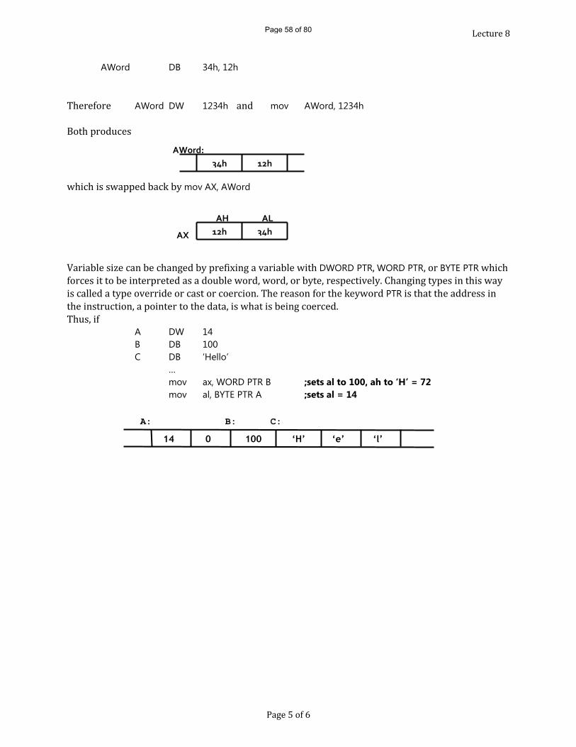
Lecture 8AWord DB 34h, 12h
Therefore AWord DW 1234h and mov AWord, 1234hBoth produceswhich is swapped back by mov AX, AWord
Variable size can be changed by prefixing a variable with DWORD PTR, WORD PTR, or BYTE PTR which forces it to be interpreted as a double word, word, or byte, respectively. Changing types in this way is called a type override or cast or coercion. The reason for the keyword PTR is that the address in the instruction, a pointer to the data, is what is being coerced.Thus, ifA DW 14B DB 100C DB ‘Hello’
…mov ax, WORD PTR B ;sets al to 100, ah to ‘H’ = 72mov al, BYTE PTR A ;sets al = 14
Page 5 of 6
34h 12hAWord:
12h 34hAX
AH AL
100 ‘H’
A:14 0 ‘e’ ‘l’
B: C:
Page 58 of 80
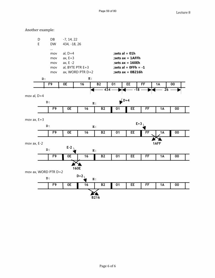
Lecture 8Another example:
D DB -7, 14, 22E DW 434, -18, 26
…mov al, D+4 ;sets al = 01hmov ax, E+3 ;sets ax = 1AFFhmov ax, E -2 ;sets ax = 160Ehmov al, BYTE PTR E+3 ;sets al = 0FFh = -1mov ax, WORD PTR D+2 ;sets ax = 0B216h
mov al, D+4
mov ax, E+3
mov ax, E-2
mov ax, WORD PTR D+2
Page 6 of 6
16 B2F9 0E 01 EED: E:
FF 1A 00434 -18 26
16 B2F9 0E 01 EE
D: E:FF 1A 00
E+3
16 B2F9 0E 01 EE
D: E:FF 1A 00
D+4
1AFF
16 B2F9 0E 01 EE
D: E:FF 1A 00
D+2
B216
16 B2F9 0E 01 EE
D: E:FF 1A 00
E-2
160E
Page 59 of 80
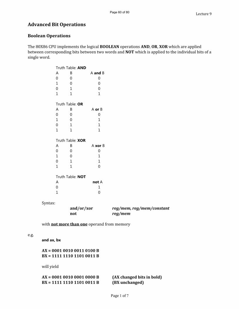
Lecture 9Advanced Bit Operations
Boolean OperationsThe 80X86 CPU implements the logical BOOLEAN operations AND, OR, XOR which are applied between corresponding bits between two words and NOT which is applied to the individual bits of a single word.Truth Table: ANDA B A and B0 0 01 0 00 1 01 1 1
Truth Table: ORA B A or B0 0 01 0 10 1 11 1 1
Truth Table: XORA B A xor B0 0 01 0 10 1 11 1 0
Truth Table: NOTA not A0 11 0Syntax:
and/or/xor reg/mem, reg/mem/constantnot reg/memwith not more than one operand from memorye.g.
and ax, bx
AX = 0001 0010 0011 0100 BBX = 1111 1110 1101 0011 Bwill yieldAX = 0001 0010 0001 0000 B (AX changed bits in bold)BX = 1111 1110 1101 0011 B (BX unchanged)
Page 1 of 7
Page 60 of 80
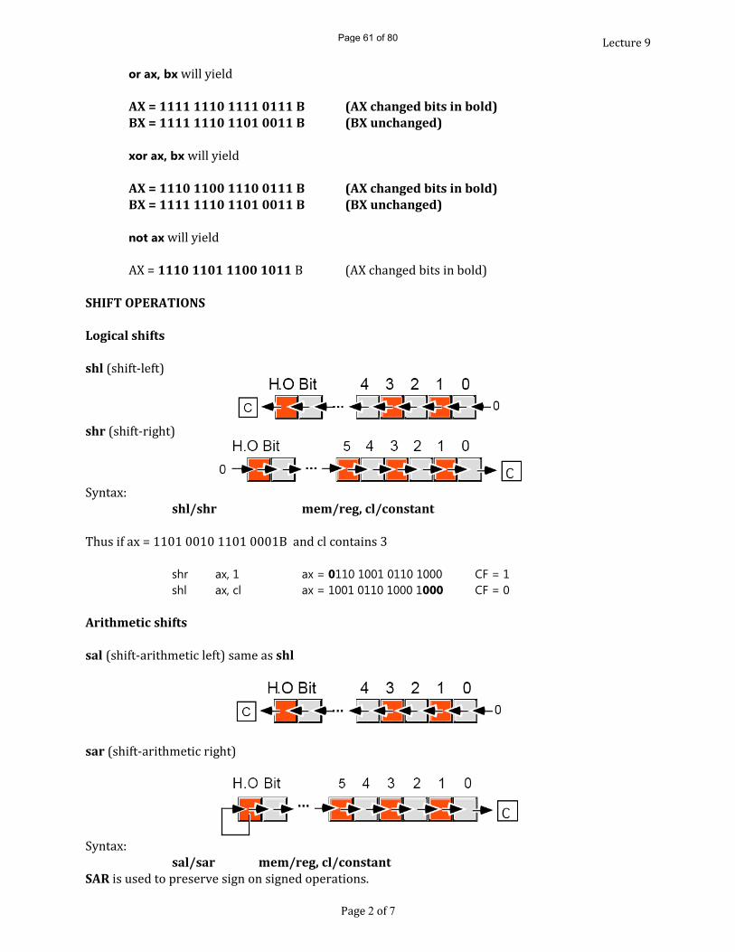
Lecture 9 or ax, bx will yieldAX = 1111 1110 1111 0111 B (AX changed bits in bold)BX = 1111 1110 1101 0011 B (BX unchanged)
xor ax, bx will yieldAX = 1110 1100 1110 0111 B (AX changed bits in bold)BX = 1111 1110 1101 0011 B (BX unchanged)
not ax will yieldAX = 1110 1101 1100 1011 B (AX changed bits in bold)SHIFT OPERATIONS
Logical shifts
shl (shift-left) shr (shift-right)Syntax:
shl/shr mem/reg, cl/constantThus if ax = 1101 0010 1101 0001B and cl contains 3shr ax, 1 ax = 0110 1001 0110 1000 CF = 1shl ax, cl ax = 1001 0110 1000 1000 CF = 0
Arithmetic shifts
sal (shift-arithmetic left) same as shl
sar (shift-arithmetic right)
Syntax:sal/sar mem/reg, cl/constant
SAR is used to preserve sign on signed operations.Page 2 of 7
Page 61 of 80
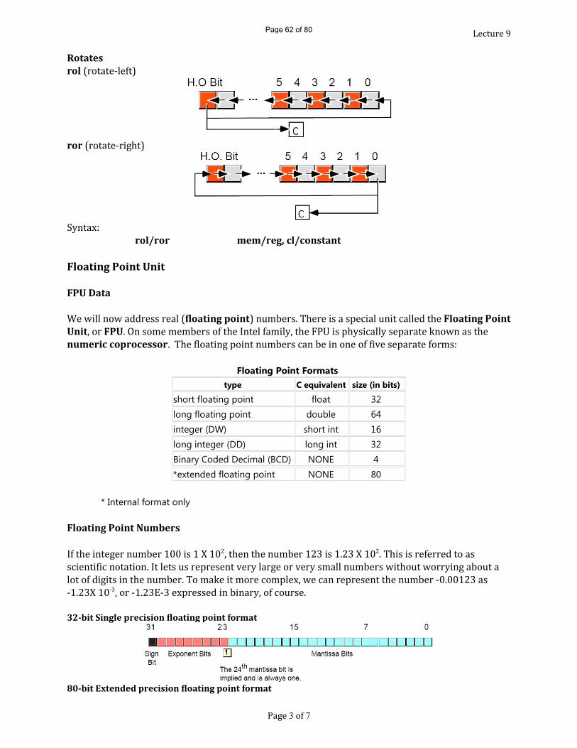
Lecture 9Rotatesrol (rotate-left)
ror (rotate-right)
Syntax:rol/ror mem/reg, cl/constant
Floating Point Unit
FPU DataWe will now address real (floating point) numbers. There is a special unit called the Floating Point Unit, or FPU. On some members of the Intel family, the FPU is physically separate known as the numeric coprocessor. The floating point numbers can be in one of five separate forms:
Floating Point Formatstype C equivalent size (in bits)
short floating point float 32 long floating point double 64 integer (DW) short int 16 long integer (DD) long int 32 Binary Coded Decimal (BCD) NONE 4 *extended floating point NONE 80
* Internal format only
Floating Point NumbersIf the integer number 100 is 1 X 10², then the number 123 is 1.23 X 10². This is referred to as scientific notation. It lets us represent very large or very small numbers without worrying about a lot of digits in the number. To make it more complex, we can represent the number -0.00123 as -1.23X 10⁻³, or -1.23E-3 expressed in binary, of course. 32-bit Single precision floating point format
80-bit Extended precision floating point format
Page 3 of 7
Page 62 of 80

Lecture 9
64-bit Double precision floating point format
• The sign bit (1 if negative and zero if positive. (bit 63) • The exponent bits (the powers of two!!!). (bits 52-62) • The mantissa. (bits 0 - 51) The exponent is biased. That is value is in the range of -1023 to 1024. The bias is 1023, when added to the exponent results in a positive number. (If the exponent is 3, then 1026 is stored as the exponent portion of the floating point number.) The mantissa is the part of the number that holds the value we are talking about, except that it is
normalized. In scientific notation, all numbers are multiplied or divided by ten so that there is only one digit in front of the decimal sign. The exponent is adjusted to compensate for that. 1.23 X 10² is the equivalent of 1.23 X 100. (102 is 100). 1.23 X 100 is 123 when you multiple it out. In the binary system, we change the power of ten to the power of two. This means that the value when we have a non-zero digit in front of decimal point, it must be a one. Therefore we can assume that it is present! This means the number is represented as: ( ( -1 )s X 1.b51b50b49...b2b1b0 X 2(exp-1023) )b51 = 0.5 if set,b50 = 0.25 if set,b49 = 0.125 if set, etc.
Range of Floating Point NumbersBinary digits and exponents do not correspond exactly to decimal digits and exponent, but the following are the approximate ranges of floating point numbers in decimal: decimal digits of precision range of exponent
short 7 10-38 to 1038 long 15 10-308 to 10308 extended 19 10-4932 to 104932
Page 4 of 7
Page 63 of 80
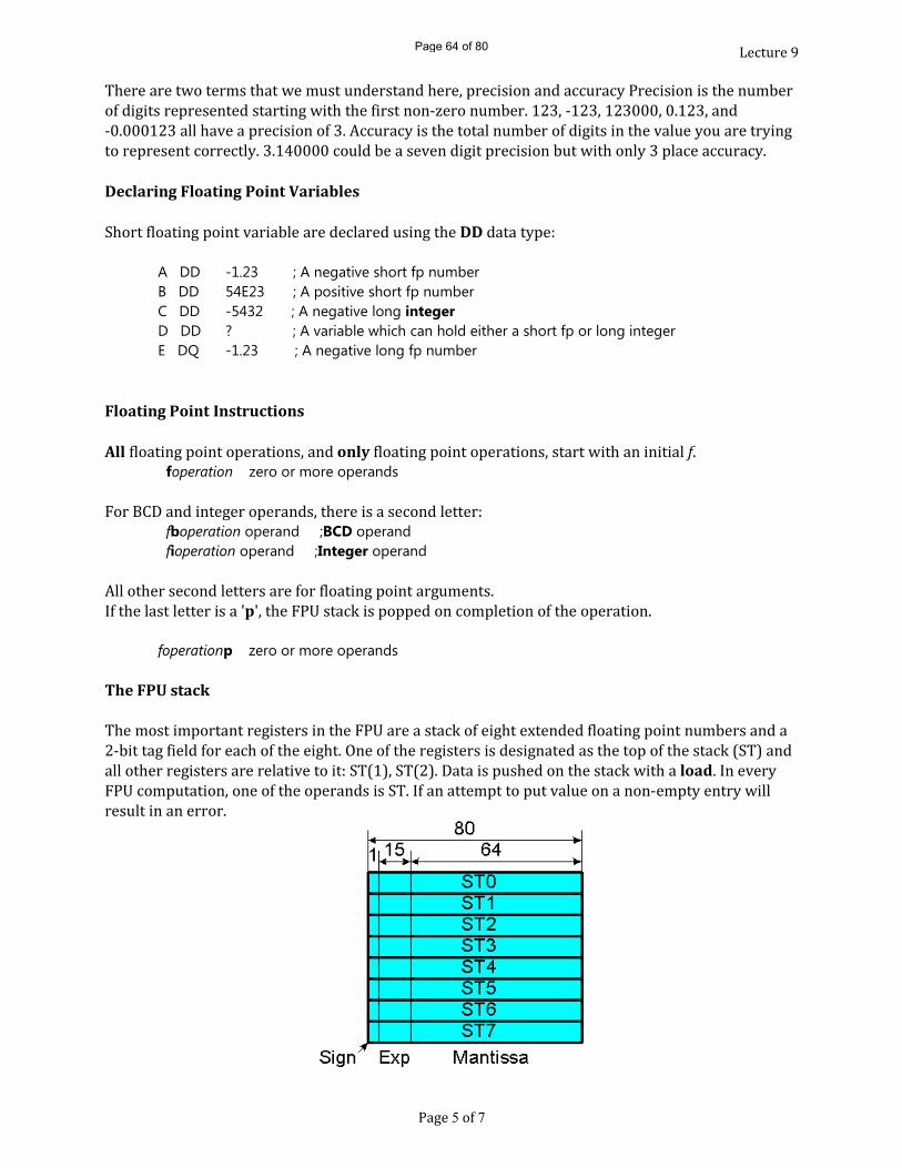
Lecture 9There are two terms that we must understand here, precision and accuracy Precision is the number of digits represented starting with the first non-zero number. 123, -123, 123000, 0.123, and -0.000123 all have a precision of 3. Accuracy is the total number of digits in the value you are trying to represent correctly. 3.140000 could be a seven digit precision but with only 3 place accuracy. Declaring Floating Point VariablesShort floating point variable are declared using the DD data type:
A DD -1.23 ; A negative short fp numberB DD 54E23 ; A positive short fp numberC DD -5432 ; A negative long integerD DD ? ; A variable which can hold either a short fp or long integerE DQ -1.23 ; A negative long fp number
Floating Point Instructions
All floating point operations, and only floating point operations, start with an initial f. foperation zero or more operandsFor BCD and integer operands, there is a second letter: fboperation operand ;BCD operand fioperation operand ;Integer operandAll other second letters are for floating point arguments. If the last letter is a 'p', the FPU stack is popped on completion of the operation. foperationp zero or more operands
The FPU stackThe most important registers in the FPU are a stack of eight extended floating point numbers and a 2-bit tag field for each of the eight. One of the registers is designated as the top of the stack (ST) and all other registers are relative to it: ST(1), ST(2). Data is pushed on the stack with a load. In every FPU computation, one of the operands is ST. If an attempt to put value on a non-empty entry will result in an error.
Page 5 of 7
Page 64 of 80
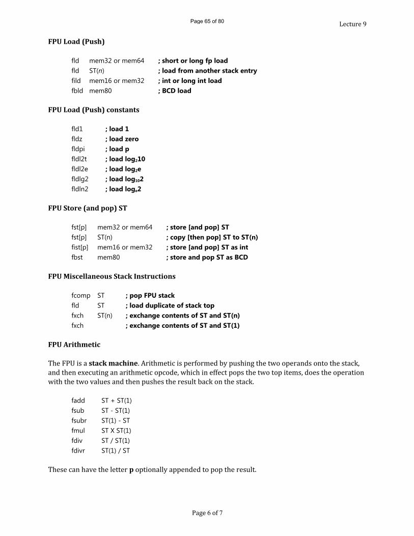
Lecture 9FPU Load (Push)
fld mem32 or mem64 ; short or long fp load fld ST(n) ; load from another stack entry fild mem16 or mem32 ; int or long int load fbld mem80 ; BCD load
FPU Load (Push) constants
fld1 ; load 1 fldz ; load zero fldpi ; load p fldl2t ; load log210 fldl2e ; load log2e fldlg2 ; load log102 fldln2 ; load loge2
FPU Store (and pop) ST
fst[p] mem32 or mem64 ; store [and pop] ST fst[p] ST(n) ; copy [then pop] ST to ST(n) fist[p] mem16 or mem32 ; store [and pop] ST as int fbst mem80 ; store and pop ST as BCD
FPU Miscellaneous Stack Instructions
fcomp ST ; pop FPU stack fld ST ; load duplicate of stack top fxch ST(n) ; exchange contents of ST and ST(n) fxch ; exchange contents of ST and ST(1)
FPU ArithmeticThe FPU is a stack machine. Arithmetic is performed by pushing the two operands onto the stack, and then executing an arithmetic opcode, which in effect pops the two top items, does the operation with the two values and then pushes the result back on the stack. fadd ST + ST(1) fsub ST - ST(1) fsubr ST(1) - ST fmul ST X ST(1) fdiv ST / ST(1) fdivr ST(1) / ST These can have the letter p optionally appended to pop the result.
Page 6 of 7
Page 65 of 80

Lecture 9Miscellaneous FPU Arithmetic
fabs ; Absolute value. Set ST to |ST| fchs ; Change sign of ST. Set ST to -ST fsqrt ; Square root. Set ST to √ST
FPU Input/OutputIt takes special software to input and output floating point numbers. There are four routines in UTIL.LIB to do this for you: Name input output GetFP none floating point number from keyboard is in ST PutFP ST on the FPU stack number is display and popped from ST
FPU Compare & BranchingThe comparisons will be done in the FPU and the decision to branch will be done in the CPU. This must be done in two steps:
FPU Compare Instructionsfcom[p] mem32 or mem64 ; compare ST to operand [and pop] fcom[p] ST(n) ; compare ST to ST(n) [and pop] fcom[p] ; compare ST to ST(1) [and pop] fcompp ; compare ST to ST(1) and pop twice ficom[p] mem16 or mem32 ; compare ST to converted integer operand [and pop] ftst ; compare ST to 0.0
Transferring the FPU Status Word to FlagsThe FPU will compare and set bits in an FPU register (status word). These must then be transferred to the Flags Register in the CPU. StatWd DW ? ; defined in the .DATA Segment ... fld B ; Load B onto ST fld C ; Load C onto ST fcom ; Compare B & C fstsw StatWd ; Store status word in StatWd mov ax, StatWd ; Move status word in ax sahf ;Transfer ah into flags register jbe OrderOK ;Is B <= C? if yes goto OrderOK fxch ;otherwise swap B & COrderOK: fstp A fcomp ST ; pop smaller item
Page 7 of 7
Page 66 of 80
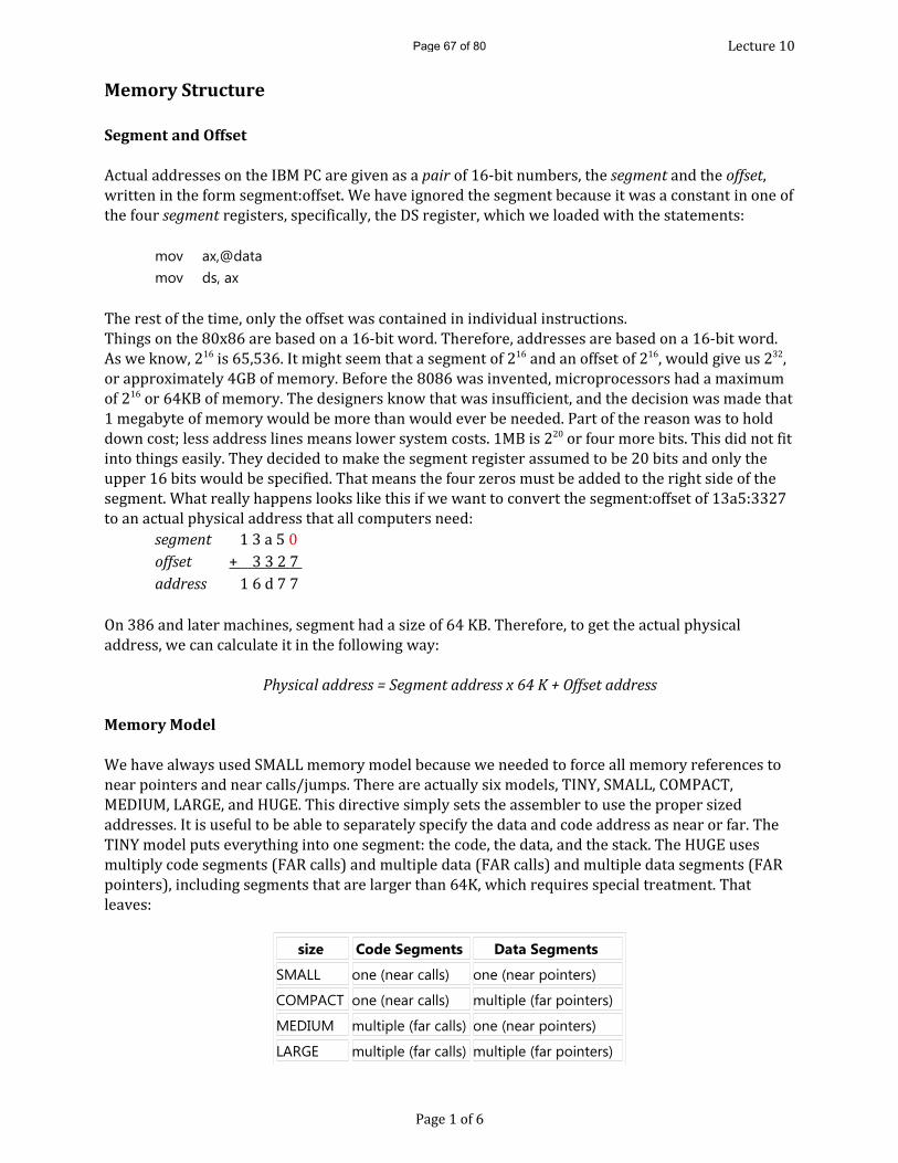
Lecture 10Memory Structure
Segment and OffsetActual addresses on the IBM PC are given as a pair of 16-bit numbers, the segment and the offset, written in the form segment:offset. We have ignored the segment because it was a constant in one of the four segment registers, specifically, the DS register, which we loaded with the statements: mov ax,@datamov ds, axThe rest of the time, only the offset was contained in individual instructions.Things on the 80x86 are based on a 16-bit word. Therefore, addresses are based on a 16-bit word. As we know, 216 is 65,536. It might seem that a segment of 216 and an offset of 216, would give us 232, or approximately 4GB of memory. Before the 8086 was invented, microprocessors had a maximum of 216 or 64KB of memory. The designers know that was insufficient, and the decision was made that 1 megabyte of memory would be more than would ever be needed. Part of the reason was to hold down cost; less address lines means lower system costs. 1MB is 220 or four more bits. This did not fit into things easily. They decided to make the segment register assumed to be 20 bits and only the upper 16 bits would be specified. That means the four zeros must be added to the right side of the segment. What really happens looks like this if we want to convert the segment:offset of 13a5:3327 to an actual physical address that all computers need: segment 1 3 a 5 0 offset + 3 3 2 7 address 1 6 d 7 7 On 386 and later machines, segment had a size of 64 KB. Therefore, to get the actual physical address, we can calculate it in the following way:
Physical address = Segment address x 64 K + Offset address
Memory ModelWe have always used SMALL memory model because we needed to force all memory references to near pointers and near calls/jumps. There are actually six models, TINY, SMALL, COMPACT, MEDIUM, LARGE, and HUGE. This directive simply sets the assembler to use the proper sized addresses. It is useful to be able to separately specify the data and code address as near or far. The TINY model puts everything into one segment: the code, the data, and the stack. The HUGE uses multiply code segments (FAR calls) and multiple data (FAR calls) and multiple data segments (FAR pointers), including segments that are larger than 64K, which requires special treatment. That leaves: size Code Segments Data Segments
SMALL one (near calls) one (near pointers)
COMPACT one (near calls) multiple (far pointers)
MEDIUM multiple (far calls) one (near pointers)
LARGE multiple (far calls) multiple (far pointers)
Page 1 of 6
Page 67 of 80

Lecture 10When there are multiple code segments, the PROCs are to return with far ret instruction, and should be referenced in other files as EXTRN Label : FAR. As a general rule, if you are combining assembly programs with high-level languages, you should use the same model in assembly as the high-level language, where the model is much more important! In order to allow a true small mode program, the assemblers automatically group .DATA and .STACK segments into a single segment. Since the stack data must come as the end of the program, the segments always occur in the order .CODE, .DATA and .STACK. Memory Addressing ModesThe 80X86 provides 17 different ways to access memory. This may seem like quite a bit at first, but fortunately most of the address modes are simple variants of one another so they’re very easy to learn. The key to good assembly programming is the proper use of memory addressing modes.The addressing modes provided by the 8086 family include Displacement-only, Base-only, Displacement plus base, Base plus indexed, and Displacement plus base plus indexed.Variations on these five forms provide the 17 different addressing modes on the 8086. The Displacement Only Addressing ModeThe most common addressing mode, and the one that’s easiest to understand, is the displacement-only (or direct) addressing mode. The displacement-only addressing mode consists of a 16-bit constant that specifies the address of the target location. The instruction mov al,ds:[8088h] loads the al register with a copy of the byte at memory location 8088h. Likewise, the instruction mov ds:[1234h],dl stores the value in the dl register to memory location 1234h (see Figure below)
Displacement Only (Direct) Addressing ModeThe displacement-only addressing mode is perfect for accessing simple variables. Of course, you’d probably prefer using names like “I” or “J” rather than “DS:[1234h]” or “DS:[8088h]”. On the 80x86 processors, this displacement is an offset from the beginning of a segment (the data segment in this example). You can think of the displacement-only addressing mode as a direct addressing mode. The examples that follow will typically access bytes in memory. Don’t forget; however, that you can also access words on the 8086 processors (see Figure below).
Accessing a wordPage 2 of 6
Page 68 of 80

Lecture 10By default, all displacement-only values provide offsets into the data segment. If you want to provide an offset into a different segment, you must use a segment override prefix before your address. For example, to access location 1234h in the extra segment (es) you would use an instruction of the form mov ax,es:[1234h]. Likewise, to access this location in the code segment you would use the instruction mov ax, cs:[1234h]. The ds: prefix in the previous examples is not a segment override. The CPU uses the data segment register by default. These specific examples require ds: because of MASM’s syntactical limitations.The Register Indirect ModeThe 80x86 CPUs let you access memory indirectly through a register using the register indirect addressing modes. There are four forms of this addressing mode on the 8086, best shown by the following instructions:
mov al, [bx]mov al, [bp]mov al, [si]mov al, [di]These four addressing modes reference the byte at the offset found in the bx, bp, si, or di register, respectively. The [bx], [si], and [di] modes use the ds segment by default. The [bp] addressing mode uses the stack segment [ss] by default.You can use the segment override prefix symbols if you wish to access data in different segments. The following instructions demonstrate the use of these overrides:
mov al, cs:[bx]mov al, ds:[bp]mov al, ss:[si]mov al, es:[di]Intel refers to [bx] and [bp] as base addressing modes and bx and bp as base registers (in fact, bp stands for base pointer). Intel refers to the [si] and [di] addressing modes as indexed addressing
modes (si stands for source index, di stands for destination index). However, these addressing modes are functionally equivalent. Note: [si] & [di] addressing modes work the same way, just substitute si and di for bx above.
[bx] Addressing Mode
[bp] Addressing ModePage 3 of 6
Page 69 of 80

Lecture 10Indexed Addressing ModeThe indexed addressing modes use the following syntax:
mov al, disp[bx]mov al, disp[bp]mov al, disp[si]mov al, disp[di]If bx contains 1000h, then the instruction mov cl,20h[bx] will load cl from memory location ds:1020h. Likewise, if bp contains 2020h, mov dh,1000h[bp] will load dh from location ss:3020.The offsets generated by these addressing modes are the sum of the constant and the specified register. The addressing modes involving bx, si, and di all use the data segment, the disp[bp] addressing mode uses the stack segment by default. As with the register indirect addressing modes, you can use the segment override prefixes to specify a different segment:
mov al, ss:disp[bx]mov al, es:disp[bp]mov al, cs:disp[si]mov al, ss:disp[di]You may substitute si or di to obtain the [si+disp] and [di+disp] addressing modes.
[bx + disp] Addressing Mode
[bp + disp] Addressing ModeBased Vs. Indexed Addressing There is actually a subtle difference between the based and indexed addressing modes. Both addressing modes consist of a displacement added together with a register. The major difference between the two is the relative sizes of the displacement and register values. In the indexed addressing mode, the constant typically provides the address of the specific data structure and the register provides an offset from that address. In the based addressing mode, the register contains the address of the data structure and the constant displacement supplies the index from that point. Since addition is commutative, the two views are essentially equivalent. However, since Intel supports one and two byte displacements, it made more sense for them to call it the based addressing mode. In actual use, however, you’ll wind up using it as an indexed addressing mode more often than as a based addressing mode, hence the name change.
Page 4 of 6
Page 70 of 80

Lecture 10Based Indexed Addressing ModeThe based indexed addressing modes are simply combinations of the register indirect addressing modes. These addressing modes form the offset by adding together a base register (bx or bp) and an index register (si or di). The allowable forms for these addressing modes are
mov al, [bx][si]mov al, [bx][di]mov al, [bp][si]mov al, [bp][di]Suppose that bx contains 1000h and si contains 880h. Then the instruction mov al,[bx][si] would load al from location DS:1880h. Likewise, if bp contains 1598h and di contains 1004, mov ax,[bp+di] will load the 16 bits in ax from locations SS:259C and SS:259D.The addressing modes that do not involve bp use the data segment by default. Those that have bp as an operand use the stack segment by default.You substitute di to obtain the [bx+di] addressing mode and di for the [bp+di] addressing mode.
Based Indexed plus Displacement Addressing ModeThese addressing modes are a slight modification of the base/indexed addressing modes with the addition of an eight bit or sixteen bit constant. The following are some examples of these addressing modes:
[BX + SI] Addressing Mode
Fig. 1 [BP + SI] Addressing Mode
Fig. 2 [BX + SI + disp] Addressing ModePage 5 of 6
Page 71 of 80

Lecture 10
Fig. 3 [BP + SI + disp] Addressing Modemov al, disp[bx][si]mov al, disp[bx+di]
mov al, [bp+si+disp]mov al, [bp][di][disp]You may substitute di in the Figure 2 to produce the [bx+di+disp] addressing mode. You may substitute di in Figure 3 to produce the [bp+di+disp] addressing mode.Suppose bp contains 1000h, bx contains 2000h, si contains 120h, and di contains 5. Then mov al,10h[bx+si] loads al from address DS:2130;mov ch,125h[bp+di] loads ch from location SS:112A; andmov bx,cs:2[bx][di] loads bx from location CS:2007.
An Easy Way to Remember the 8086 Memory Addressing ModesThere are a total of 17 different legal memory addressing modes on the 8086: disp, [bx], [bp], [si], [di], disp[bx], disp[bp], disp[si], disp[di], [bx][si], [bx][di], [bp][si], [bp][di], disp[bx][si], disp [bx][di], disp[bp][si], and disp[bp][di]9. You could memorize all these forms so that you know which are valid (and, by omission, which forms are invalid).However, there is an easier way besides memorizing these 17 forms. Consider the chart in Figure 4 below: If you choose zero or one items from each of the columns and wind up with at least one item, you’ve got a valid 8086 memory addressing mode. Some examples:• Choose disp from column one, nothing from column two, [di] from column 3, you get disp[di].• Choose disp, [bx], and [di]. You get disp[bx][di].• Skip column one & two, choose [si]. You get [si]• Skip column one, choose [bx], then choose [di]. You get [bx][di]Likewise, if you have an addressing mode that you cannot construct from this table, then it is not legal. For example, disp[dx][si] is illegal because you cannot obtain [dx] from any of the columns above.
Table to generate valid 8086 Addressing ModesPage 6 of 6
Page 72 of 80

Lecture 11InterruptsAn interrupt causes the computer to stop doing what it is doing, save the current state of the interrupted program and transfers control to an interrupt handler, which is in another program or the operating system. When it saves the state information, it must save all the of necessary information so that the interrupted program can resume without any indication of being interrupted. An interrupt is said to be transparent to the interrupted program. There are hardware and software interrupts. In general, interrupts can be viewed as a good thing, when the interrupts handlers are properly written and interrupts don't happen too often. Examples of when interrupts are used are: 216 280
• Completion of I/O, such as key presses and releases. This allows for computations in what would be the wasted time between keystrokes and greatly increasing the computers productivity (throughput). • Computers have a real-time clock that will cause a set number of interrupts per second. This keeps the time-of-day clock up to date and to give each user a time-slice so that the computer can be a time-shared system or multiprocessing system. There are also
interval timers which allow the system to be interrupted at the request of the applications programmer. • Error interrupts such as divide by zero, illegal opcode, illegal memory address (does not exist or is allocated to another program) and hardware error conditions (out of paper on the printer, floppy disk door open, etc). • Execution of a group of instructions such as INT 21 as we saw earlier. Each interrupt has an interrupt number which is communicated to the CPU in some way by the causer of the interrupt. This number is used to index a table of handler addresses (vectored
interrupts). Interrupts can be enabled or disabled. There are some operations that can only take place reliably when interrupts are disabled; however disabling interrupts is not something that we want to happen indiscriminately! Additionally, there are some interrupts that can not be disabled, such as caused by power failure or machine errors. We can disable some by changing a bit in a mask, and they are called maskable interrupts and the others are called non-maskable interrupts. More than one interrupt can occur during the execution of an instruction. When this happens, at the end of the instruction, the CPU picks one interrupt to be serviced. The others are held until the end of another instruction, when another one will be serviced. There are many ways to classify interrupts: • Hardware vs. Software generated interrupts. • Internal (within the CPU) vs. External interrupts. • Asynchronous vs. Synchronous interrupts. • Maskable vs. Non-Maskable interrupts.
Page 1 of 3
Page 73 of 80

Lecture 11Interrupt Processing on the 80X86 There are 256 interrupts possible on the 80x86 computers. Any one of which can be caused to executing the instruction:
INT n ;cause interrupt nInterrupts can be enables or disable with the instructions: sti ;set I flag to 1, enablecli ;set I flag to 0, disableMemory locations 0 - 1023 hold a four-byte address (segment:offset) in a interrupt vector table for each interrupt handler. The interruption mechanism is:
1. When a device wishes to cause an interrupt, it makes an interrupt request that includes the number of the interrupt. When arriving in the CPU it is held until the completion of the current instruction. 2. At the end of each instruction, before the next instruction is fetched, the CPU checks to see if there are any interrupts waiting. If there is, one is selected for interrupt service and the others are held. 3. The CPU does the following items: 1. Push the flag register onto the stack 2. Disable interrupts. 3. Push the cs and IP registers. 4. Load the address of the handler. The rest is up to the specific interrupt handler, however, it should quickly re-enable interrupts (which implies that the handler itself can be interrupted). Any register that will be used must first be pushed onto the stack. The handler then does what it is suppose to do. Finally, the handler must pop the saved registers, and issue a special return:
iret ;return from interrupt.This will pop the IP, cs and flag registers, which will also re-enable the interrupts. The interrupt vector table is setup by the boot-up procedure in the BIOS when the computer starts up, setting addresses of interrupt handlers for interrupts that the BIOS handles, and initializing the rest to a handler that consists of nothing but the iret instruction. This makes it easy to upgrade the handlers in future releases of the operating system or even to have a different operating system altogether. When the operating system loads, it puts in the address of its handlers where necessary. WARNING: Since interrupts occur at any time, they wipe out anything that had been put onto the stack previously. Never assume that something you popped is still on the stack waiting for you!
Page 2 of 3
Page 74 of 80

Lecture 11Interrupt HandlerIf we want to write an interrupt, we would have to change the address of the handler in the Interrupt Handler Vector Table. There are two macros, _SetInvVec and _SaveInvVec, that will take care of that item. Then we would have to write a handler in the following form:
Handler PROC ; push all registers used
… ; process interruptiret ; pop all pushed registers
Handler ENDP
Types of Interrupts
• Hardware vs. Software generated interrupts.A hardware interrupt is a signal created and sent to the CPU that is caused by some action taken by a hardware device. E.g. keystroke depressions and mouse movements cause hardware interrupts. A software interrupt is an interrupt caused by an instruction in the program. E.g. int 21h
• Internal (within the CPU) vs. External interrupts. An internal interrupt is a signal for attention sent to a computer's central processing unit by another component of the computer. An external interrupt is caused by an external source such as the computer operator, external sensor or monitoring device, or another computer.• Asynchronous vs. Synchronous interrupts. An asynchronous interrupt can occur randomly at any time. E.g. mouse movements.A synchronous interrupt is one that always occur in the same stage of execution. E.g. Divide by Zero error or page fault. • Maskable vs. Non-maskable interrupts. A maskable interrupt are hardware interrupts that can be allowed to occur or prevented from occurring by software.A non-maskable interrupt can not be ignored and is typically used to signal attention for non-recoverable hardware errors. E.g. Power Failure.
Page 3 of 3
Page 75 of 80

BS
c (Hons) S
oftware E
ngineering
BS
c (Hons) C
omputer S
cience & N
etwork
Security
BS
E/06/FT
- BC
NS
/06/FT – B
SE
/05/PT
Exam
inations for 2007 – 2008 / Sem
ester 2
MO
DU
LE: MIC
RO
PRO
GR
AM
MIN
G
MO
DU
LE CO
DE: H
CA 2101
Duration: 2¼
Hours
Instructions to Candidates:
1. Attem
pt all 3 questions.
2. Start your answer to each question on a fresh page.
3. Questions do not carry equal m
arks
3. Maxim
um m
arks achievable = 100
4. Silent calculators are allow
ed in the Exam
ination Room
.
5. Appendix is provided.
This question paper contains 3 questions and 4 pages.
AT
TE
MP
T A
LL 3 QU
ES
TIO
NS
QU
ESTION
1: (32 Marks)
a) Describe the follow
ing terms:
(i) Von Neum
ann Bottleneck
(ii) Delayed B
ranching
(iii) Superscalar P
rocessor
[3+2+3 marks]
b) Give the hexadecim
al content of the ax register after each of the following
sequential instructions.
�
.DATA
��
�prim
e��DB�
�101�
��
��
.CODE�
��
��
mov�
�ax,�666��
��
��
��
mov��
�al,�prim
e��
ax=��
��
�rol�
�ax,�2�
��
ax=��
��
�div�
�ah�
��
ax=��
��
�shr�
�al,�1�
��
ax=��
��
�neg�
�ax�
��
ax=��
��
��
[3+2+4+2+3 marks]
c) Calculate the apparent speed of m
emory for a 20 nanoseconds cache w
ith a miss
rate of 10% and 90 nanoseconds local m
emory.
[4 marks]
d) Calculate the overall throughput for 1001 sequential instructions assum
ing a four-
stage pipeline and each instruction goes through fetch (10 nanosecond), decode
(2 nanosecond), execute (5 nanosecond) and write-back (20 nanosecond)
stages.
[6 marks]
Page 76 of 80

QU
ESTION
2: (34 Marks)
a) Give tw
o reasons why sub-program
s are preferred over macro-instructions.
[4 marks]
b) Translate and optimize the follow
ing high-level statement into assem
bly
language.
IF ((X==6) O
R (Y
>9)) AND
(Z<7) THE
N X
=Y ELS
E X
=Z
��
��
[12 marks]
c) Write a program
using floating-point operations in Reverse P
olish Notation to
calculate the volume of a cone by prom
pting the user to enter the radius of the
base and the height of the cone as positive real numbers.
Volume of cone = 1/3 x � x radius
2 x height
(You can assume that radius and height to be unsigned bytes)
An sam
ple run would be:
Enter radius:
1.7��
Enter height: 2.5 �
�
Volume =
7.5660023074
[18 marks]
QU
ESTION
3: (34 Marks)
a) Prototype a m
acro called AP w
hich takes 4 integer parameters n (num
ber of
terms),a
(first term), l(last term
) and Sum (sum
of n terms), given that:
Sum = (a+l)*n/2
[8 marks]
b) Give a diagram
matic exam
ple of the based index addressing mode?
[4 marks]
c) Suppose you m
ade the following declarations:
D
DB
-66, 29, 120
E
DW
258, -30, 17
G
ive the contents of the destination register in each case:
mov al, D + 2
mov ax, E - 2
mov ax, E + 2
mov al, BYTE PTR E + 2
mov ax, WORD PTR D + 2
[3+3+3+3+3 marks]
d) Give a diagram
matic interpretation of the hardw
are stack and explain the purpose of the Stack Pointer (SP
).
[7 marks]
***END
OF PA
PER***
Page 77 of 80

�
��
���������
� �������
�������
�����
�������
��������������
�����
��������
�������
��
���!�"#
�$���
��
��!�"#
�%��
������ ���'��*$+������
�����'
��
��
�����
��
��
��
��
��
��
��
����
��
����
������
�����������
�����
�����!"�#���
���
�����$������������������
���
�������%%&����� ���
���
����������������������������� �����������������
���
���� ��������������������
��������!
�����"��##
$��
�&''�*
�����������������/�;�����@����������������J /�/
K�U������� ��&
���������������������/� ������U
\�� ��� ���*
���
"'��+�������,�,��$�������&+�����������-,�!��/
�����������
,#
#�
.1
#�,
44�9:
��
#;<
��
5���������6�-�
��7�8
�^'��������������/ ���������@���
������,�,�%�������/�����,���$�%������� ��������@������
�������@�������� �����������
����������������������9&#
��7�;
@^&
�����������������������/�������
������������ ������������������� �
�����$����������/���
������ �����������_`
���/����������
������������ ��������
� ��������/��
9<#��7�;
�^&
��������������J���������������������#�������� ��� ������� ��������� ���������j
������ �� �����/������ ������� ����������������������{$����������/^|�/���/��{�����������/^|��\������{����������/^���/���
� ��j@����{�$����������/^�������}
9=#��7�;
/^U
\�� ������������ �������
�~�
��
�������
��������������
������ ���������������
��
�����/������� ��
J�*
'�&������� ��
9&><#��7�;
�����������
Page 78 of 80

5���������6�-�
��7�8
������������'�?���$�#
�%�����������������%��� �������������$'����������� ���
������� ���~
.DATA
Chiffre
DB
77
.CODE
mov
al, Chiffre
shl
al
neg
al
ror
al
add
al, 1
9�@<@<@<@�#��7�;
���
� ������������������
����������������������������� ������� ���� /����|��
���/����� ����
��������������~�
����������
�����������
������������� �����
��
��������/������~
������������ ����↵
������� ������� ����↵
������������ ����↵
�� �� �����������������
������������ ������������������������������������ ��� ����������������
9�&#��7�;
�����������
5�������<�6�-�
��7�8
�^�
� �����������j�� � ��/������
@���������������������������������
������ �����\���� ��~
����������� ���������������������������������
� ��
������������������������ ������������������� �
9B#��7�;
���
� ������������������
��������������������������������/���< ����������/��
����������������� �������� ��/�����/ �����/����
����� �����J���������������#
�$��������/���������
������������������ ���
���������� ��
������������������ ����� �������!�� �������������������
���� ��!�
����\��
�������/�@�~
������������ �����↵↵
��������������� ������↵
������������� ������ �↵
������������������� �
9��#��7� ;
�^�
����/��������/������/�@������������ �������
�}
��JK�$'������� �������
������� ������� ��
������!#
������/��VV�����
���$7�,������9�@�@�@�#
��7�;
�����������
Page 79 of 80

5�������&�6�-�
��7�8
���
����/��������/������/�@��WK��X�Y�,,��!���/�W�!X������}�
9&#��7�;
���
J����/ ������
�� ���\������������W��������?���������!��
�/�}9=#
��7�;
�^�
�����������/������������
���/������� ���~
���
������ �
��� ��������
� J������$����������������������������!������ �����������~
�������������������
��������
��������
������������!���
�������"!���!��
9<@<@<@<@<;
ZZZ����V �,��ZZZ
�����������
Page 80 of 80