Embed Size (px)
Citation preview
ED 099 511
TIT1.E
INSTITUTIONFEPORT NOPUB DATENOTE
FDPS PRICEDESCPIPTOPS
ABSTRACT
DOCUMENT RESUME
CE 002 588
Module Fourteen: Parallel AC Resistive-ReactiveCircuits; Basic Electricity and ElectronicsIndividualized Learning System.Bureau of Naval Personnel, Washingtor4 D.C.NAVPE7S-94556-14aJan 72145p.; For other modules in the series, see CE 002573-589
MP -$Q.75 RC-$6.60 PLUS POSTAGECourse Content; *Electricity; *Electronics;Individualized Instruction; Individualized Programs;Industrial Education; Military Training; PostSecondary Education; *Programed Instruction;Programed Materials; Study Guides; Trade andIndustrial Education; Units of Study (SubjectFields)
In this module the student will learn about parallelFL (resistive-inductance) , PC (resistive- capacitive) , and PCL(resistive-capacitive-inductance) circuits and the conditions thatexist at resonance. The module is divided into six lessons: solvingfor quantities in RL parallel circuits; variational analysis of RLparallel circuits; parallel RC and PCL circuits; parallel resonance;effective resistance in parallel PL circuits; and parallel resonanceexperiments. Each lesson consists of an overview, a list of studyresources, lesson narratives, programed instructional materials, andlesson summaries. (Author/BP)
NAVPERS 94558-14a
BASIC ELECTRICITY AND ELECTRONICS
INDIVIDUALIZED LEARNING SYSTEM
MODULE FOURTEEN
PARALLEL AC RESISTIVE- REACTIVE
CIRCUITS
Study Booklet
BUREAU OF NAVAL PERSONNEL
Jan uary 1972
OVERVIEWMODULE FOURTEEN
PARALLEL AC RESISTIVE-REACTIVE CIRCUITS
In this module you will learn about parallel RL, RC and RCL circuits
and the conditions that exist at resonance.
F0,- you to more easily learn the above, this module has been divided
into the following s'x lessons
Lesson I
Lesson 11
Lesson 111
Lesson IV
Lesson V
Lesson VI
Solving for Quantities in RL Parallel Circuits
Variational Analysis of RL Paral.el Circuits
Paralle RC and RCL AC Circuits
Parallel Resonance
Effective Resistance in Parallel RL Circuits
Parallel Resonance Experiment
TURN TO THE FOLLOWING PAGE AND BEGIN LESSON I
1
NAVPERS 9558-14a
BASIC ElECTRICITY AND ELECTRONICS
INDIVIDUALIZED LEARNING SYSTEM
-er3
MODULE FOURTEENLESSON I
Solving for Quantities in RL Parallel Circuits
Study Booklet
Bureau of Naval Personnel
January 1972
OVERVIEW
LESSON I
Solving for Quantitie,, in RL Parallel Circuits
Fourteen-I
In this lesson you will study and learn about the following
review parallel resistive' ctrLuits
parallel resistive-inductive circuits
methods of solution of RL parallel circuits
BEFORE YOU START THIS LESSON, PREVIEW THE LIST OF STUDY RESOURCES
ON THE NEXT PAGE
b
Stud\ Resources
LIST OF STUDY RESOURCES
LESSON I
Solving 1or Quantities in RL Parallel Circuits
Fourteen-I
Tu learn tne material in this lesson, you have the option of choosing,
according to your experience and preferences, any or all of the
folloing
STUDY BOOKLET
Lesson Narrative
Programmed Instruction
Lesson Summary
ENRICHMENT MATERIAL
NAVPERS 93400A-lb "Basic Electricity, Alternating Current "
Fundamentals of Electronics Bureau of Naval Personnel
Washington,DC' U S Government Printing Office, 1965
AUDIO-VISUAL
Slide-Sound Presentation "Solving for I
Tin a Parallel RL Circuit,"
YOU MAY NOW STUDY ANY OR ALL OF THE RESOURCES LISTED ABOVE YOU MAY
TAKE THE PROGRESS CHECK AT ANY TIME,
5
Narrative Fourteen-I
NARRATIVE
LESSON I
Solving for Quantities tri RL Parallel Circuits
Revie.ing Rules for Parallel Resistive Circuits
Several modules back, you learned to solve for quantities in
parallel circuits which were purely resistive. Now we will brieflyrevie the rules you used
A150V
130P, 30a
3
301/
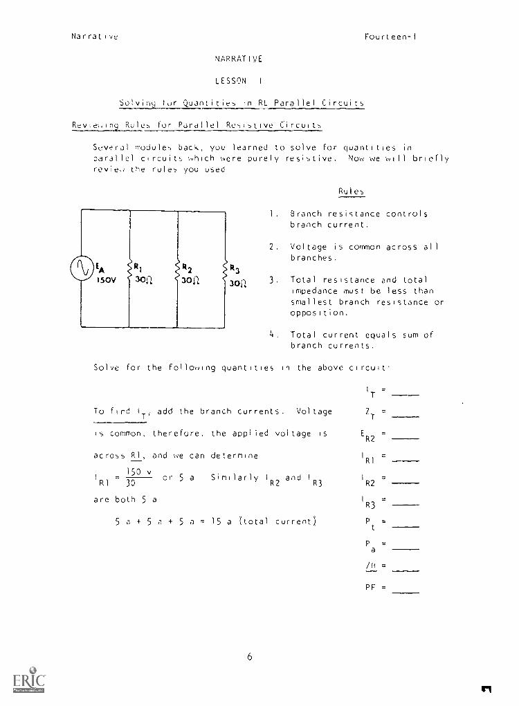
Rules
1. Branch resistance controlsbranch current.
2. Voltage is common across allbranches.
3. Total resistance and totalimpedance must be less thansmallest branch resistance oropposition.
Total current_ equals sum ofbranch currents.
Solve for the following quantities in the above circuit.
I
T
To find IT, add the branch currents. Voltage 2T
=
is common, therefore, the applied voltage is ER2
=
across RI, and we can determine I
R1=
15I = or 5 a Similarly and I I
RI 30
0 v
IR2 an R3 R2
are both 5 a I
R3
5 a+ 5 a+ 5 a= 15 a (total current) Pt
=
Pa
=
/o =
PF =
6
15
Narrative Fourteen-I
To solve for ZT
, you can u'e Ohm's Lau.
E
ZT I
150 vZTT 15 a
ZT = 10
Solving forER2
As voltage is common in a parallel circuit, the voltage drop across
any of the branches is the same as the applied voltage, or 150 volts.
Solving for Pt
True power can be determined by the P = I2R formula In this
purely resistive circuit I = 15 a, RT 10 , therefore,P
t
= 2250 w or 2 25 kw
Solving for Pa
Apparent power in a purely resistive circuit is equal to true power.
You can prove this by the formula Pa = E x I, P = 150 v x 15 a .
2 25 kw
Solving for Px
Reactive power is not present in a purely resistive circuit
Angle Theta
In a purely resistive circuit. /- is zero because E and I are in
phase.
Power Factor
You know that the power factor in a purely resistive circuit is
unity, or 1.
What would happen to total current in the parallel
circuit we have been analyzing if frequency weredoubled?
You should know the answer is nothing. Current in parallel circuitsis determined by branch resistance, and frequency usually does notaffect the value of carbon except for some skin effect at extremelyhigh frequencie-.)
7
Narrative Fourteen-I
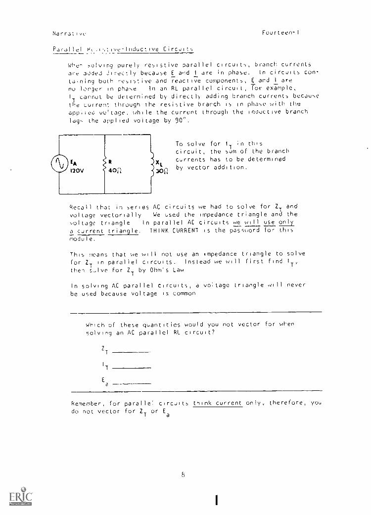
Parallel r-t .1,,tive-Inductive Circuits
Wher ,,olving purely resistive parallel circuits, branch currents
are added directly because E and I are in phase. In circuits con-
taining both resistive and reactive components, E and I are
no longer in phase In an RL parallel circuit, for example,1
1cannot be determined by directly adding branch currents because
the current through the resistive branch is in phase with the
appiied voltage, while the current through the inductive branchlag, the applied voltage by 900.
To solve for I
Tin this
circuit, the sum of the branch
XLcurrents has to be determined
, by vector addition,10i4
Recall that in series AC circuits we had to solve for ZT
and
voltage vectorially We used the impedance triangle and the
voltage triangle In parallel AC circuits we will use only
a current triangle. THINK CURRENT is the password for this
module.
This weans that we will not use an Impedance triangle to solve
for ZT
in parallel circuits. Instead we will first find I
T'then ,,--lve for Z
Tby Ohm's Law
In solving AC parallel circuits, a voltage triangle will never
be used because voltage is common
Which of these quantities would you not vector for whensolving an AC parallel RL circuit?
ZT
IT
Ea
Remember, for parallel circuits think current only, therefore, youdo not vector for Z
Tor E
a
8
Narrative
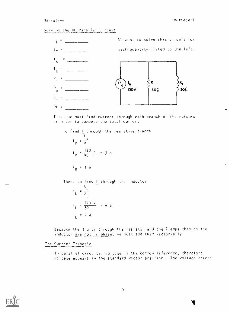
Solving the RL Pdrallel Circuit
IT
ZT
IR =
l.
Pt =
Pd
/ =
PF
Fourteen-I
We want to solve this circuit for
each quantity listed to the left.
XL
30i1
Ftflt WP must find current through each branch of the netwo,-Kin order to compute the total current
To find I through the resistive branchEa
I =R R
120 vI
R 40= 3 a
I
R= 3 a
Then, to find I through the inductorE
=L XL
120 vI
L 30= 4 a
IL = 4 a
Because the 3 amps through the resistor and the 4 amps through the
inductor are not in phase, we must add them vectorially.
The Current Triangle
In parallel circuits, voltage is the common reference, therefore,
voltage appears in the standard vector position. The voltage across
9
111

Narrative Fourteen-I
IL
40
tt
4a
/R 30EA
tR 3o EA40. Recall that in a purely inductive circuit,
voltage leads current oy an angle of 90'(ELI). For this reason E and I
Larc
4900 out of phase, with Ealeading, there-
fore, the 1 vector is aa-j quentity.
(Note that the -j is the result ofchanging the reference )
the resistor and the cuitent through theresistor are in phase, therefore I i,,
plotted on the standard vector posiR tion.
IR 30. IA
40i 4r\ ,
3.311 , Vector ally adding the values of theA' branch currents produces the total
circuit current. Therefore, 1
Tis
5 a.
This information can be expressed in rectangular notation, givingfirst the 1 through the resistor, then the I through the inductor,thus 3 a J4 a
In polar form, this is expressed 5 /-53.1° (You recall this is
/ for a 3-4-5 triangle.)
Solving for ZT
Now that we have found I
T'you can solve for total impedance
by Ohm's Law (Remember We do not vector for ZT
in parallelcircuits )
120V R 4011
Solving for True Power
E
Z aT I
T
120 /0°
300,ZT 5 /-53 I°
(Ea
is our reference,
therefore, we assignan angle of 0°.)
ZT
= 24 /53.1°
Y00 know that power is consumed only by r2esistance, To findthe value of P
t ,
use the formula, P = I R. I in this case mustbe the current tnrough the resistive branch, not total circuitcurrent
10
Narrative
Pt
- I
2R
Pt
= (3)2
x 40
Pt
= 9 x 40
Pt
= 360 w
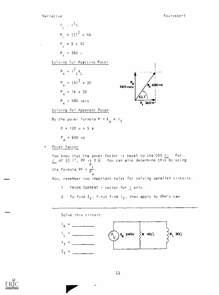
Solving for Reactive Power
Px .2ILX
1.
Px
= (4)2
x 30
Px = 16 x 30
Px = 480 ears
Solving for Apparent Power
By the power formula P = Ea x I
P= 120 v x 5 a
Pa
= 600 va
Power factor
Pi
480 vans
T
Pt36
Fourteen-1
You know that the power factor is equal to the COS /6 For
/ of 53 10, PF is 0,6. You can also determine this by usingP
t
the formula PF = --,Pa
Now, remember two important rules for solving parallel circuits.
1 THINK CURRENT vector for I only.
2 To find 2T'
first find I
T'then apply by Ohm's Law
Solve this circuit,
I
R=
I=L
I
T
ZT
=
11
i
Narrative Fourteen-I
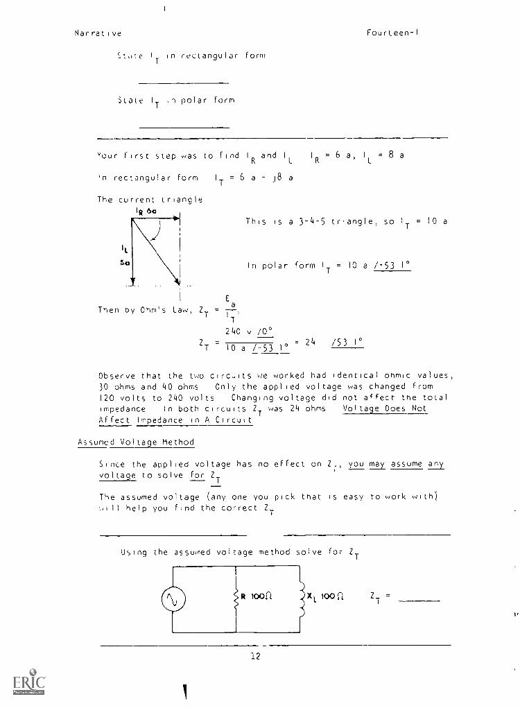
State I
1-
in rectangular form
State I
Tin polar form
Your first step was to find IR and I
LI
R= 6 a, I
L= 8 a
'n rectangular form I
T= 6 a J8 a
The current triangleIR 6a
i
e)
IL
Nn
This is a 3-4-5 triangle, so IT = 10 a
In polar form IT = 10 a /-53 10
Ea
,Then by Ohm's Law, ZT = T
240 v /00
ZT 10 a /-53 10= 24 /53 1°
Observe that the two circuits we worked had identical ohmic values,30 ohms and 40 ohms Only the applied voltage was changed from120 volts to 240 volts Changing voltage did not affect the totalimpedance In both circuits Z
Twas 24 ohms Voltage Does Not
Affect Impedance in A Circuit
Assumed Voltage Method
Since the applied voltage has no effect on Z,'
you may assume anyi
vol tage to solve for Z,!
The assumed voltage (any one you pick that is easy to work with)0111 help you find the correct ZT
Using the assumed voltage method solve for ZT
loou Z__
12
li
1,
Narrative BEST COPY AYPHInic Fourteen-I
Yuu mdy have realized a workable, easy, voltage to assume is 100volL,, IT = 1 41 a /-45°, and Z = 70 7 :. /45' Whatever
volt39e you ised, ZT
= 70 7 /45°
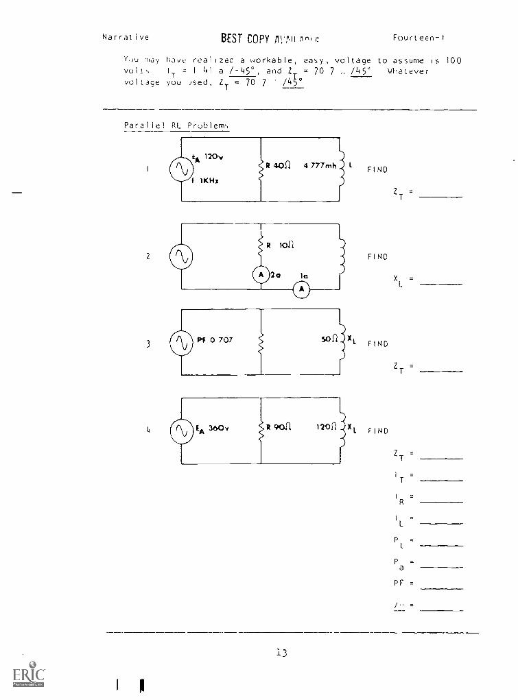
Parallel RL Problem,,
I
2
3
4
tA 120v
I\./
f IKH:
8401/ 4 777mh 1
13
FIND
FIND
FIND
FIND
ZT =
XL
=
ZT
=
ZT
=
I =T
IR =
IL =
Pt =
Pa
=
PF =
/ =
Narrative
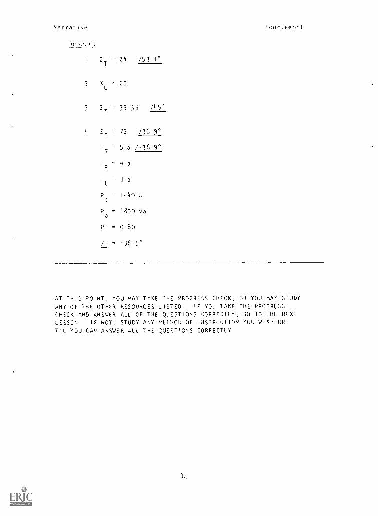
(\n,,uer,,
Fourteen-I
I Z = 24 /53 1°
i
T
x 20
3 ZT
= 35 35 /45°
ZT
= 72 /36 9°
1
T= 5 a /-36 9°
I
R= 4 a
I
L= 3 a
P = 1440 pt
P = 1800 vaa
PF = 0 80
/ = -36 9°
AT THIS POINT, YOU MAY TAKE 1HE PROGRESS CHECK, OR YOU MAY STUDYANY OF THE OTHER RESOURCES LISTED IF YOU lAKE THE PROGRESSCHECK AND ANSWER ALL OF THE QUESTIONS CORRECTLY, GO TO THE NEXT
LESSON IF NOT, STUDY ANY METHOD OF INSTRUCTION YOU WISH UN-
TIL YOU CAN ANSWER ALL THE QUESTIONS CORRECTLY
21
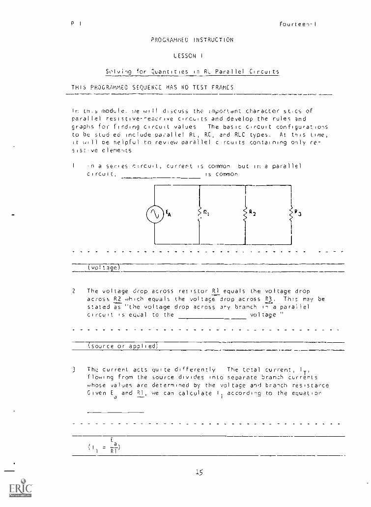
P I Fourteen-I
PROGRAMMED INSTRUCTION
LESSON I
ScIving for Quantities in RL Parallel Circuits
THIS PROGRAMMED SEQUENCE HAS NO TEST FRAMES
In cnis module, ue will discuss the ;mportdnt characteristics ofparallel resistiveeacrive circuits and develop the rules andgraphs for finding circuit values The basic circuit configurationsto be studied include parallel RL, RC, and RLC types. At this time,it will be helpful to review parallel circuits containing only re-sistive elements
In a series circuit, current is common but in a parallelcircuit, is common
(voltaia--
2 The voltage drop across resistor RI equals the voltage dropacross R2 which equals the voltage drop across R3. This may bestated as the voltage drop across any branch in a parallelcircuit is eqpal to the voltage "
(source or applied)
3 The current acts quite differently The total current, IT,
flowing from the source divides into separate branch currentswhose values are determined by the voltage and branch resistanceGiven E
aand RI, we can calculate according to the equation
15
P I Fourteen-I
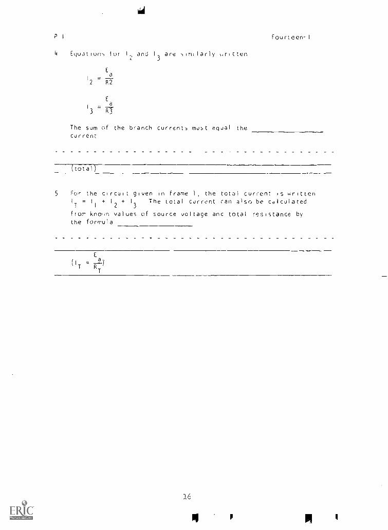
4 Equatiow, tor I2 I
3
are -,imilarly mittenL
Ea
i =2 R2
Ea
i = __3 R3
The sum of the branch currents must equal the
current
(total)
5 For the circuit given in frame 1, the total current is writtenIT=I
1
+ 12 +I3
The total currnt can also be calculated
from knoim values of source voltage anc total resistance bythe formula
E
(IT Ttl)'T
16
Pi P Pi I
P.! Fourteen-I
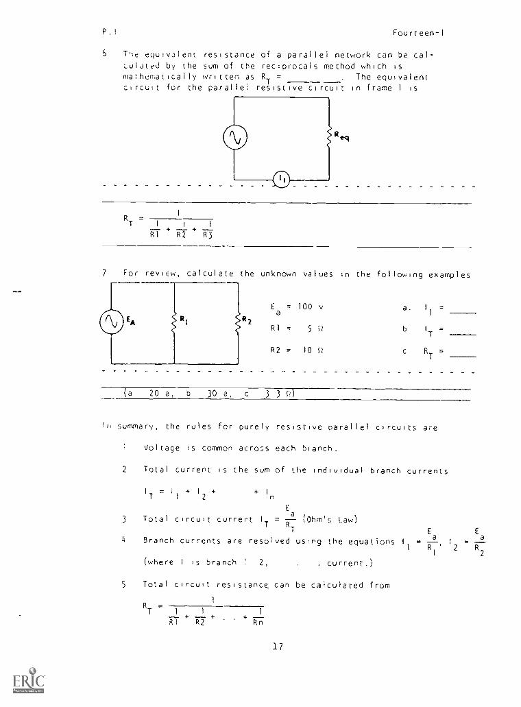
6 The equivalent resistance of a parallel network can be cal-Lulatrd by the sum of the reciprocals method which ismathematically written as RT = . The equivalentcircuit for the parallel resistive circuit in frame 1 is
I
RT
=1 1 1
RI R2 R3
7 For review, calculate the unknown values in the following examples
Ea
= 100 v a I
1
=
RI = 5 0 b I
T=
R2 = 10 Q c RT
=
20 a, b 30 a, c 3 3 c2)
In summary, the rules for purely resistive parallel circuits are
1 Voltage is common across each branch.
2 Total current is the sum of the individual branch currents
I = I + I + + I
T 1 2 n
E
3 Total circuit current I = -- (Ohm's Law)T R
T E E
4 Branch currents are resolved using the equations I = = 2.
I R1
' 2 R2
(where 1 is branch 2, . . current.)
5 Total circuit resistance can be calculated from
I
R7
=I 1 1
RI R2 + Rn
17
P I. Fourteen-I
6 Pf)ase difference between curre.)t and voltage is zero (/ = 0).
7 True p(A,er equals apparent power since the load is purely
resistive
= (I )2R =P =E I
T T J 1 T
8 Power factor is unity PF = 1
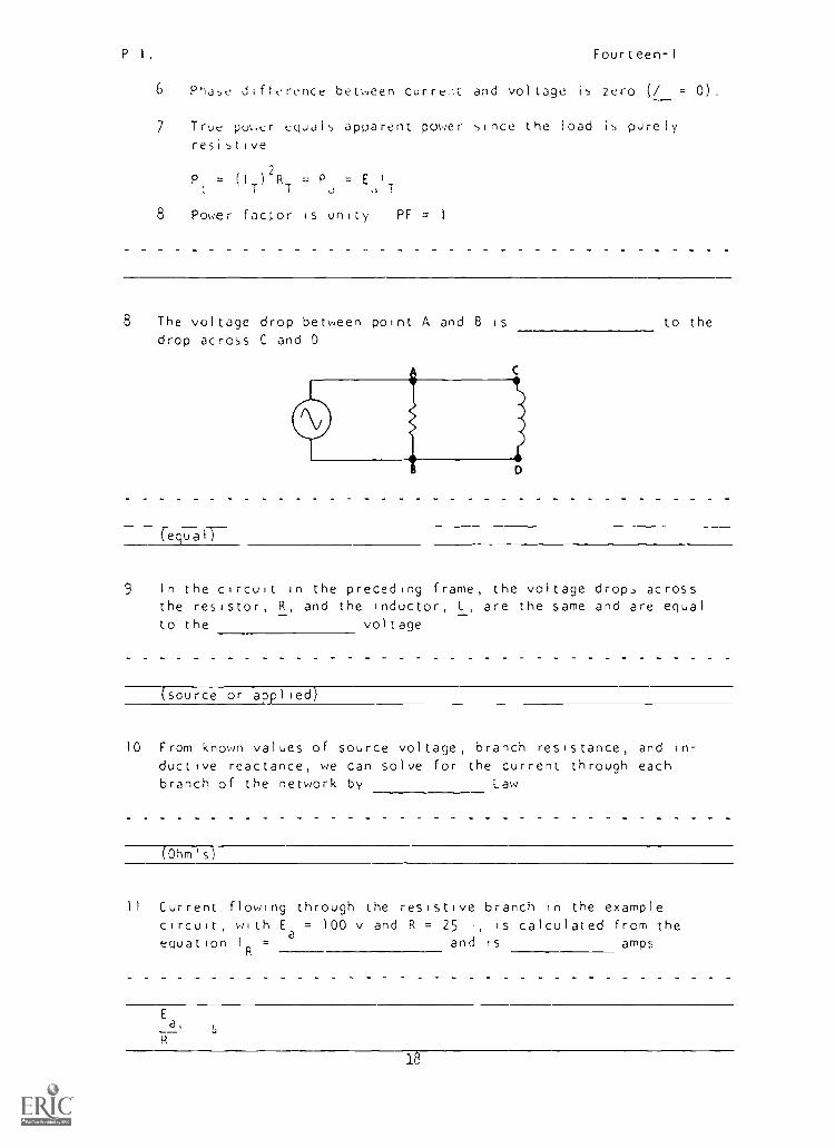
8 The voltage drop between point A and 8 is to the
drop across C and D
(ecl.uall-
9 In the circuit in the preceding frame, the voltage drop, acrossthe resistor, R, and the inductor, L, are the same and are equal
to the voltage
(source or applied)
10 From known values of source voltage, branch resistance, and in-ductive reactance, we can solve for the current through eachbranch of the network by Law
(Ohm' s)
11 Current flowing through the resistive branch in the examplecircuit, with E = 100 v and R = 25 i, is calculated from theequation IR = and is amps
Ea,
7- 4
18
P I Fourteen-I
12 Wc ore obit! to calculate I from the equation I =a
'
since
the voltage drop across the resistor Is equal toR R
Tsource or applied voltageT
13 Similarly, the voltage drop across the inductive branch equalssource voltage Branch current, IL, can be calculated fromthe equation I
L= and is
amps, with Ea
= 100 v and XL
= 20
Ea
X L'5
14 In a parallel RL circuit, total current, IT, cannot be obtainedby directly adding IR and IL as in a purely resistive circuitsince the two currents are
(out of phase)
15 With the voltage across each branch common and the currents in
the resistive and inductive branches out of phase, wesolve for total current by addition of individual
branch currents
(vector-)
16 In a parailL1 RL circuit, voltage is common and can be repre-sented by a vector in the position
(standard or reference)
19
P.I. Fourteen-1
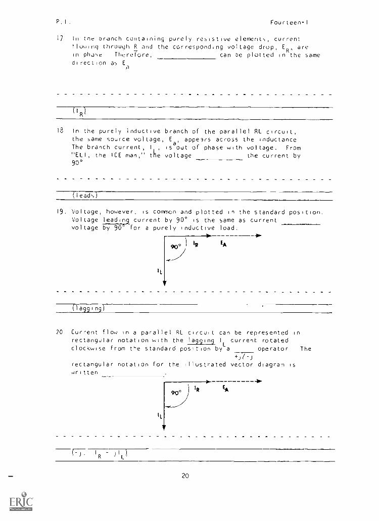
17 In the branch containing purely resistive elements, current!lowing through R and the corresponding voltage drop, ER, arein phase Therefore, can be plotted in the samedirection as E
a
18 In the purely inductive branch of the parallel RL circuit,the same source voltage, Ea, appears across the inductanceThe branch current, I is out of phase with voltage. From"ELI, the ICE man," tke voltage the current by90°
(leads)
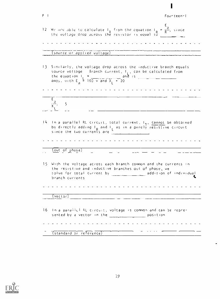
19. Voltage, however, is common and plotted in the standard position.Voltage leading current by 90° is the same as currentvoltage by 90° for a purely inductive load.
4IR900 EA
(lagging)
20 Current flow in a parallel RL circuit can be represented inrectangular notation with the lagging IL current rotatedclockwise from the standard position by a operator The
rectangular notation for the illustrated vector diagram iswritten
9o°IR
EA
IR j 1 )
L'
20
P I. Fourteen-I
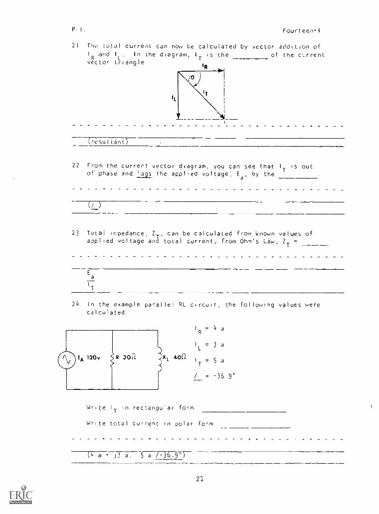
21 The total current can now be calculated by vector addition of1 and I
L'gIn the diagram, 1 is the
R Tof the current
vector triangleIR
(resultantT-
22 From the current vector diagram, you can see that IT is outof phase and lags the applied voltage, Ea, by the
23 Total impedance, ZT, can be calculated from known values ofapplied voltage and total current, from Ohm's Law, ZT
Ea
IT
24 In the example parallel RL circuit, the following values werecalculated
I = 4 a
I = 3 a
120v R 30f1 XL 40(1I = 5 a
T
Write I
Tin rectangular form
/ = -36 9°
Write total current in polar form
(4 a - 5 a /-36.9')
21
I
P I Fourteen-I
25 In the ;,ftLidiny exJmple, total impedance is determined fromE
the formula, 2TT
We cannot simply divide 120 volts byT
5 but ,-u,t al,(: take inio account the phase difference,
/ . pular notation ZT
=
(120 v /0', the phase angle for Ea
is zero since it is
the reference value )
120v /0°26 For example ZT ca-77-31:77
to be ZT 7-
the total impedance is calculated
(24 736.9'
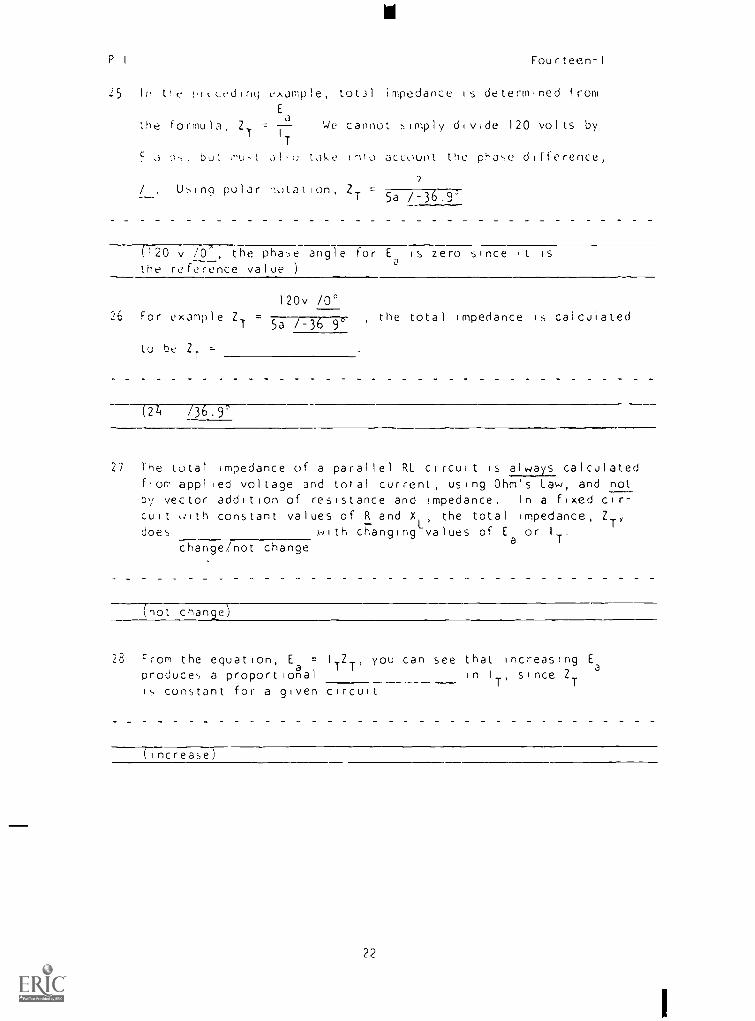
27 The total impedance of a parallel RL circuit is always calculatedfrom applied voltage and total current, using Ohm's Law, and notby vector addition of resistance and impedance. In a fixed cir-
cuit with constant values of R and XL, the total impedance, Z
does with changing values of Ea
or IT.
change/not change
(not change)
28 From the equation, E = ITZT, you can see that increasing E
produces a proportiona al in I
T'since Z
Ts constant for a given circuit
(increase)
22
P 1 fourteen -1
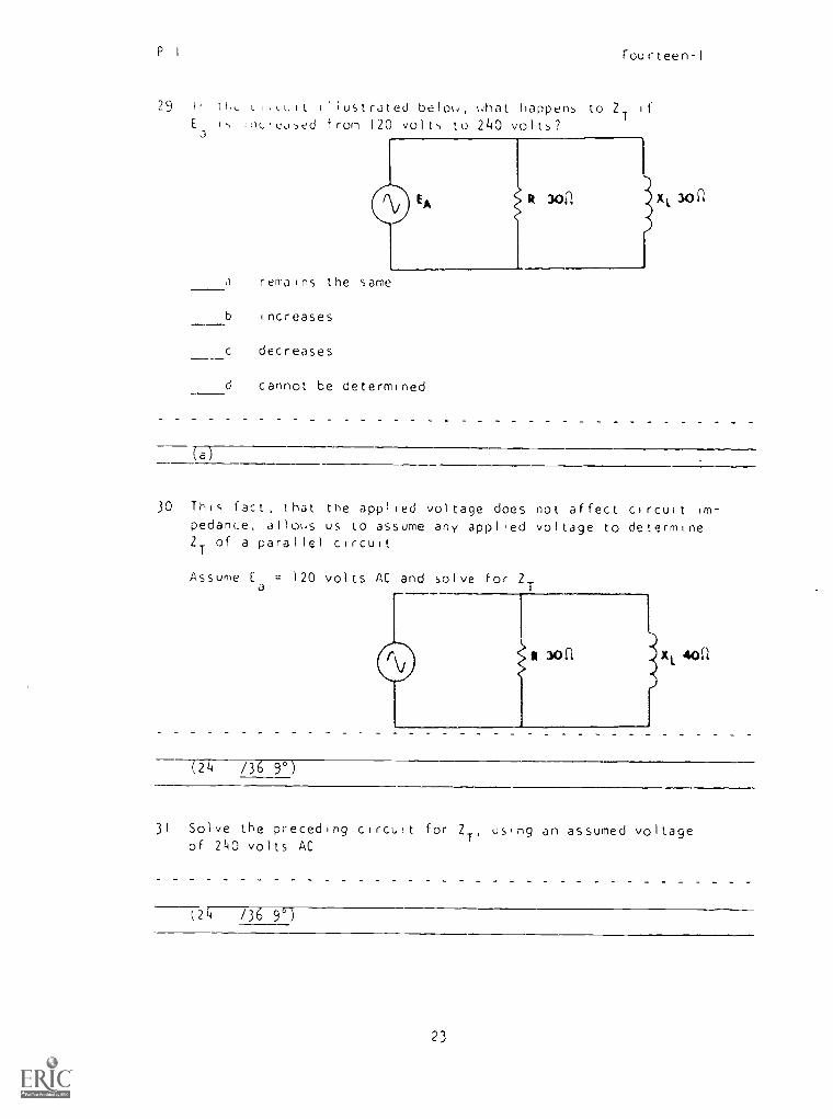
29 I th, LI,cult illustrated belo, chat happens to ZT
if
E s inc'eused from 120 volts to 240 volts?a
J remains the same
b increases
c decreases
d cannot be determined
(a)
30 This fact, that the applied voltage does not affect circuit im-
pedance, allows us to assume any applied voltage to determine2T
of a parallel circuit
Assume [a
= 120 volts AC and solve for 2T
(24 /36 9°)
31 Solve the preceding circuit for ZT'
using an assumed voltageof 240 volts AC
;24 /36 9°)
23
P I Fourteen-I
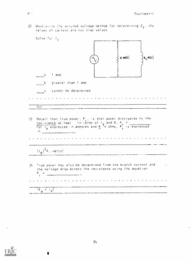
32 When using the assumed voltage method for determining 2T'
the
values ut current are not true values
Solve fur IT
a I amp
b greater than 1 amp
c cannot he determined
)R 443c1 )(141011
(c
33 Recall that true power, Pt
, is that power dissipated by the
resistance as heat In terms of 1 and R, P =
For I
Rexpressed in amperes and R in ohms, P
t
is expressedft
t
in
( I
R
2) R
'
watts)
34 True power may also be determined from the branch current andthe voltage drop across the resistance using the equationP =
t
(E x 1-7--a R
2L
II
I
P.I Fourteen-I
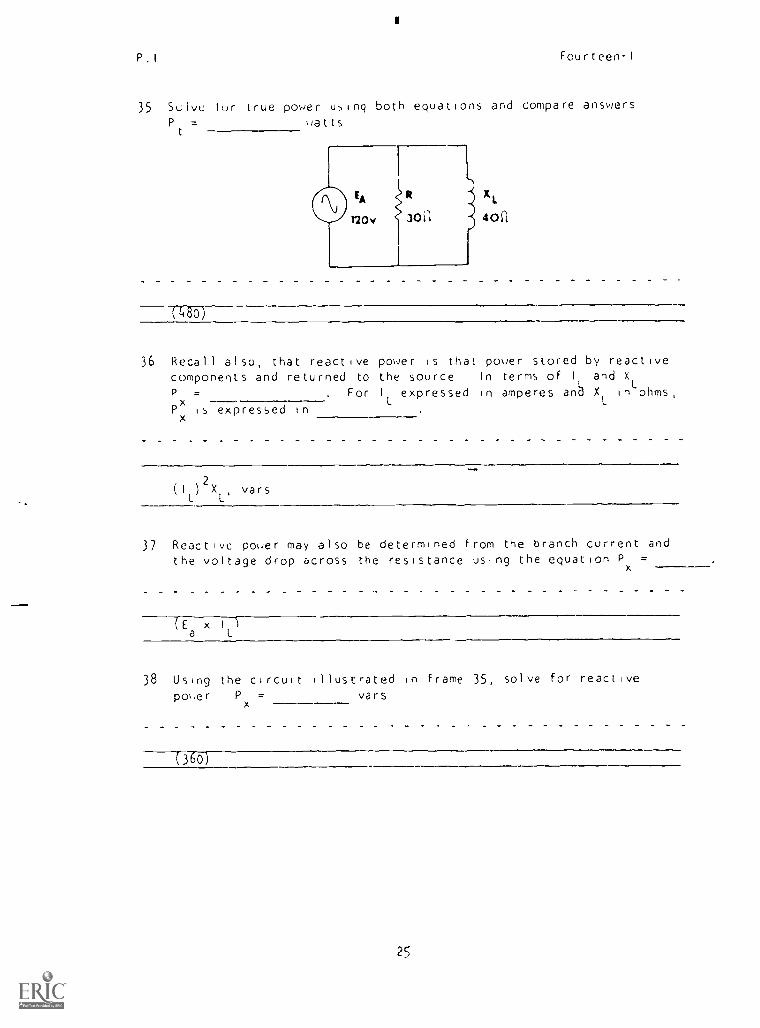
35 Suivu for true power using both equations and compare answersP
t
. watts
xt.
40a
(4-80
36 Recall also, that reactive power is that power stored by reactivecomponents and returned to the source In terms of II and X
P = . For I expressed in amperes and XL
int.
ohms,
Px
is expressed inx
(It.
)
2Xl'
vars
37 Reactivc power may also be determined from the branch current andthe voltage drop across the resistance using the equation P ---,
x
(Ea x 1
t.
)
38 Using the circuit illustrated In frame 35, solve for reactive
power Px
= vars
c360)
2S

P I
Fourteen-I
39 Appdr,, r puer, Po, 15 a combination of the purr dissipated by
the re,i,t1),_ Lomponents and '.he power stored by the reactive
component,
In term,, of E and I
T'Pa
=a
Px
360 vors
(EaI 11
40 When Ea
,s in volts and I
Tin amperes, apparent power is expressed
In
Solve for Pa
A 41
120v 3o1 ) 4011t
Pa
=
(volt-amperes, 600 va)
41 The power factor for any circuit is defined as the ratio of true
power to power It may aso be expressed as tieof the /
Tapparent, cosine)
26
rOU teen
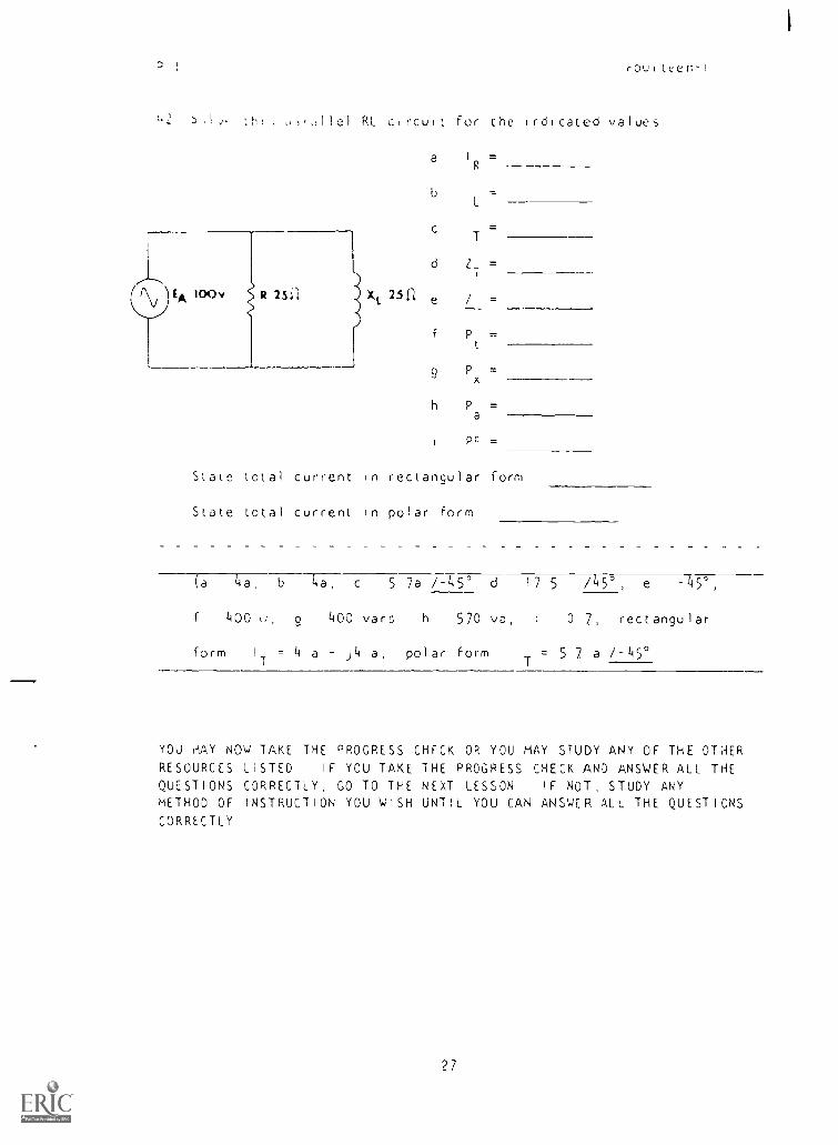
,i,dllel RL circuit for the Irdicated values
a I =
b I
L
I=
d ZT =
2511 =
f Pt
9 Px =
h Pa =
pc =
State total current in rectangular form
State total current in polar form
(a Lia, b 4a, c 5 7a /-45', d 17 5 /5°, e -45',
f 400 g 400 vars, h 570 vc, 0 7, rectangular
form I = 4 a j4 a, polar form I T= 57 a /-45'
YOU HAY NOW TAKE THE PROGRESS CHECK OR YOU MAY STUDY ANY OF THE OTHERRESOURCES LISTED IF YOU TAKE THE PROGRESS CHECK AND ANSWER ALL THEQUESTIONS CORRECTLY, GO TO THE NEXT LESSON IF NOT, STUDY ANYMETHOD OF INSTRUCTION YOU WISH UNTIL YOU CAN ANSWER ALL THE QUESTIONSCORRECTLY
27
Summary Fourteen-I
SUMMARY
LESSON 1
Solvinu tur Quantities in RL Parallel Circuits
In Module Six Nu were introdu_ed to the rules governing parallelcircuits Before tile discussion of the more complex AC circuitperhaps a brief review of these rules, using a purely resistivecircuit, will be nelotul
1 In a parallel network voltage is the commor, value
Ea
= E, = E2
= E
3
=
2 Total circuit current eq,als the sum of the branch currents
IT 1 + 12 + 13 + + I
n
3 Branch resistance determines branch current, with the branchcontaining the larger opposition having the smaller current
4 Total circuit resistance is smaller than the smallest branchresistance
When dealing w,th purely resistive circuits, we are able to add thebranch currents directly to f nd total current, E and I are in phase,
/ is 0, and the circuit power factor is 1 If e reactive element
TTnductance in this case) is placed in the circuit, there is a
phase shift beteen the applied voltage and circuit current Because
of this, other forms of computation must be used For example, theindividual branch currents can no longer be added algebraically to find1
T'vectorial addition must be used
In series AC circuits, current is the common value and the in-
dividual voltage drops are added vector ally to find E In parallel
circuits, )oltage is the common value and current divi8es betweenthu brunches Hence, voltage not current, must be used as the vectorreference in a parallel circuit
28
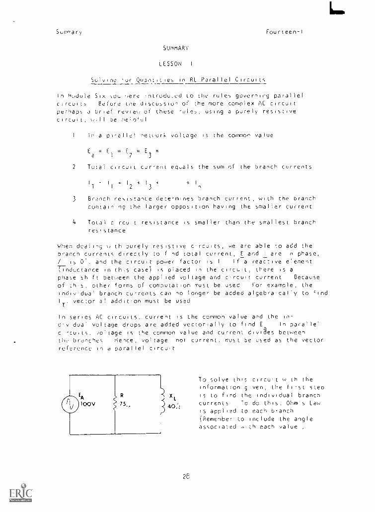
To solve this circuit with theinformation given, the first step
is to find the individual branchcurrents To do this, Ohm's Lawis applied to each branch(Remember to include the angleassociated 410-) each value ,
Summary Fourteen-I
E
i5 /0'
100 /0° 100 /0°
= I 33a /0` I=
L X 40 /4-Q0° 2 5 a /-90°
E
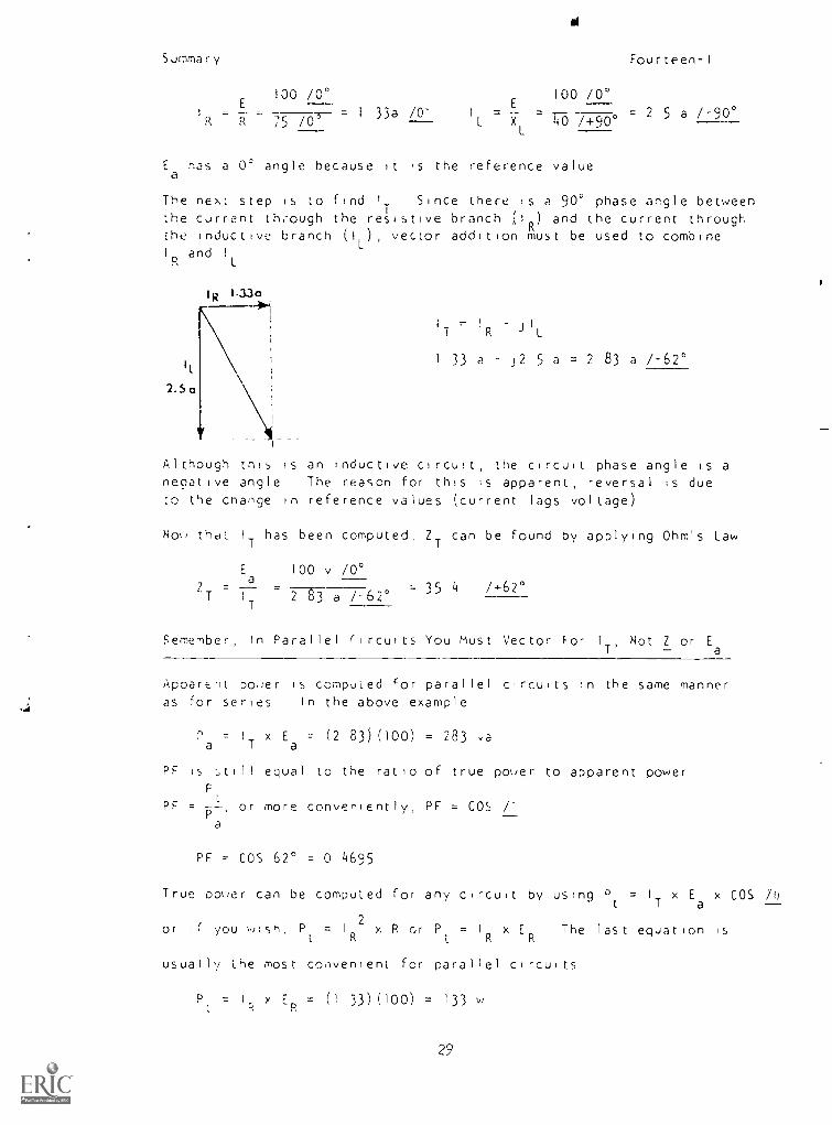
ahas a 0° angle because It 's the reference value
The next step is to find 1 Since there is a 90° phase angle betweenthe current through the resistive branch I ) and the current throughthe inductive branch (IL), vector addition must be used to combineI and I
It
2.5 a
IT R ) IL
33 a j2 5 a= 2 83 a /-62°
Although this is an inductive circuit, the circuit phase angle is a
neoative angle The reason for this is apparent, reversal is due
to the change in reference values (current lags voltage)
Noi that I
Thas been computed, Z
Tcan be found by applying Ohm's Law
Ea
100 v /0°
ZT= =I
T2 83 a /-62°
35 4 / +62°
Femember, In Parallel circuits You Must Vector For IT, Not Z or Ea
Apparent power is computed for parallel circuits in the same manneras For series In the above example
= I
Tx E
a= (2 83)(100) = 283 va
PF is ;till equal to the ratio of true power to apparent power
PF =P
or more conveniently, PF = COS /-
a
PF = COS 62° = 0 4695
True Douer can be computed for any circuit by using Pt = I x Ea x COS /0
or if you wish, = IR2 x R or Pt = I x ER The last equation is
usually the most convenient for parallel circuits
Er, = 33) (100) = 133 w
29
Summary Fourteen-I
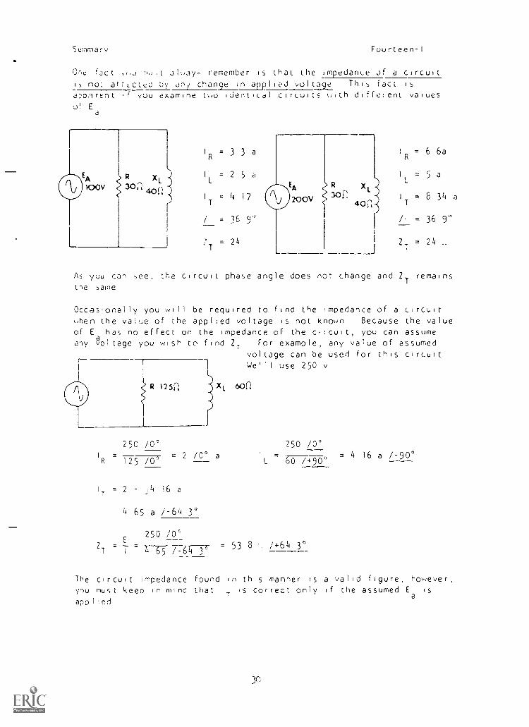
One fact (,:r r,,t alway, remember is that the impedan<e of a circuit15 not atrt.ctec by tiny, change in applied voltage This fact is
ap.,)rent. .f you examine two identical circuits with different valuesof E
a
R x,
30n 402
IR = 3 3 a
I = 2 5 a
I = 4 17
/ = 16 9'
T= 24
L
EA
200V
R x301
40 n
IR = 6 6a
1 = 5 a
IT = 8 34 a
/. = 36 90
= 24 ..___J
As you can see, be circuit phase angle does nor change and ZT
remains
the same
Occasionally you will be required to fino the impedance of a c:rcuitwhen the value of the applied voltage is not known Because the valueof E has no effect on the impedance of the circuit, you can assume
aany voltage you wish to find Z
TFor example, any value of assumed
voltage can be used for this circuitWe'll use 250 v
250 /0°
R 125 /0= 2 /0° a
IT = 2 j4 16 a
4 65 a /-64 3°
E250 /0°
2T T /-64 3°= 53 8
250 /0°1 =
60 /+90°
+64 3°
= 4 16 a /-90°
The circuit impedance found in this manner is a valid figure, however,you must keep in mind that
ITis correct only if the assumed E
ais
applied
30
I
Summary Fourteen-I
In ,elle) k.irt_uits, the circuit is either predominately resistive orpredominuLely reactive depending upon which device developer the 1Jr-getvoitage drop A parallel circuit, however appears reactive orre,,istive depending on which branch carries largest current
AT THIS POINT, YOU MAY TAKE THE LESSON PROGPESS CHECK, OR YOU MAYSTUDY THE LESSON NARRATIVE OR THE PROGRAMMED INSTRUCTION OR BOTHIF YOU TAKE THE PROGRESS CHECK AND ANSWER ALL OF THE QUESTIONS COR-RECTLY, GO TO THE NEXT LESSON IF NOT, SELECT ANOTHER METHOD OFINSTRUCTION UNTIL YOU CAN ANSWER ALL THE QUESTIONS CORRECTLY
31
NAVPERS 94958-14a
BASIC ELECTRICITY AND ELECTRONICS
INDIVIDUALIZED LEARNING SYSTEM
MODULE FOURTEEN
LESSON I 1
VariatIonal Analysis of RL Parallel Circuits
Study Booklet
Bureau of Naval Personnel
January 1972
3
I
rii,
OVERVIEW
LESSON II
,H ,i,.,1 ,-,n,-,1 ..,,_ ii! RL Parallel Circuit',
Fourieen-II
H ;n is le,,5on you will study and learn about the follomng
-effect of a change in frequency
-effect of a change in applied voltage
-effect of a change in resistance
-effect of a change in inductance
-..r :FE ''-.)L, STPT T'IS LESSON PREVIEW THE LIST OF STUDY RESOURCES
iN T-1E NEff P,1GE
Study Resources Fourteen-II
LIST OF STUDY RESOURCES
LESSON it
\Jariatirnal Analv,,lis of RL Parallel Circuits
To learn the material in this lesson, you have the option of choose,.;,
.2,,uidInq to your e,perience and preferences, any or all of the
tollouing
STUDY BOOKLET
Lesson Narrative
Programmed Instruction
Lesson Summary
ENRICHMENT MATERIAL
NAVPERS 93400A-lb "Basic Electricity, Alternating Current "
Fundamertals of ElectroniLs Bureau of Naval Personnel
Washington, D C U S Government Printing Office, 1965
YOU MAY NOW STUDY ANY OR ALL OF THE RESOURCES LISTED ABOVE YOJ
TAKE THE PROGRESS CHECK AT ANY TIME
35
Narrative
NARRATIVE
LESSON II
Variational Analy,,is of RL Parallel Circuits
Fourteen-11
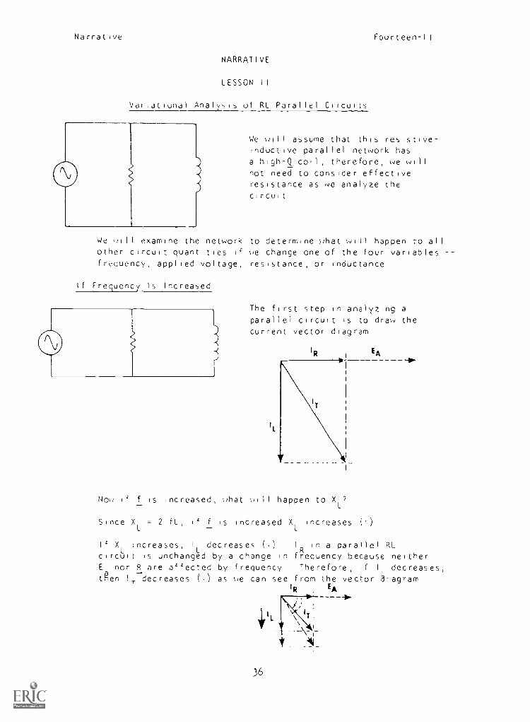
We will assume that this resistive-Inductive parallel network hasa high-Q coil, therefore, we willnot need to consider effectiveresistance as we analyze thecircuit
We ,Jill examine the network to determine what will happen to allother circuit quantities if we change one of the four variablesfrequency, applied voltage, resistance, or inductance
If Frequency Is Increased
The first step in analyzing aparallel circuit is to draw thecurrent vector diagram
No if f is increased, what will happen to XL
7
Since XL
= 2 fL, if f is increased XL
Increases (1)
If X Increases, I decreases ()L
I in a parallel RLcircuitit is unchanged by a change in frequency because neitherE nor R are affected by frequency Therefore, if I decreases,ten 1 decreases (1.) as we can see from the vector bgram
TIR EA
-I1 lo-
I '
T1
36
Narrative Fourteen-II
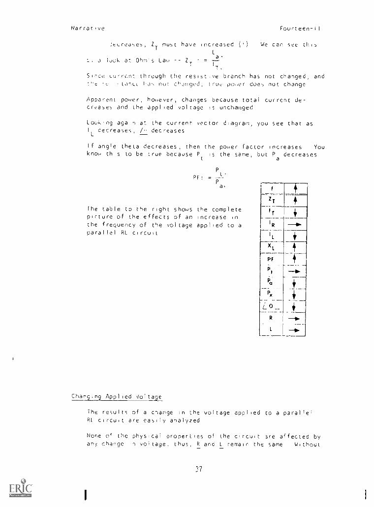
JeLrea5e5'
ZTmust have increased H We
E
look at Ohm's Law Z, =a
IT
Since Lurrcnt through the resistive branch has not changed, and
can see this
t'-e , L. I , tdrILL '_1', not cHinged, (rue po.er does not change
Apparent power, however, changes because total current de-creases and the applied voltage is unchanged
Looking again at the currenr vector diagram, you see that asI
L '
decreases /_i decreases
If angle theta decreases, then the power factor increases Youknow this to be true because P
t
is the same, but Padecreases
P
PF! .t
Pia,;
The table to the right shows the completepicture of the effects of an increase inthe frequency of the voltage applied to aparallel RL circuit
Changing Applied Voltage
The results of a change in the voltage applied to a parallelRL circuit are easily analyzed
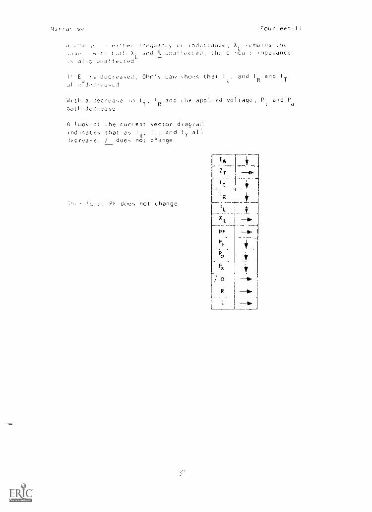
None of the physical properties of the circuit are affected byany change in voltage, thus, R and L remain the same Without
37
NJ,-r-at Ive Fourteen-II
i'I rirt ur inductance, X lernaln5 lhL,u ,)I h X and R naf the C. rCu; impedance;5 a I 50 utla eL
It E d,:c r Ohm', Law ,,hous that I
L
and IR and IT
JI
W; Iii a decrease in I1 and Lie applted voltage, P and P
T' R t aboth decrease
A look Jt Lhe current vector dtayar.-.
Indicate, that as I
R'I and H. all
lecrea,e, / does not change
L PE doe, not change
FA
Z T
IT
I -K
I
____ _._ _ _
XL
1'1
Pt. . _
P
:---/ PO
R
Narrative
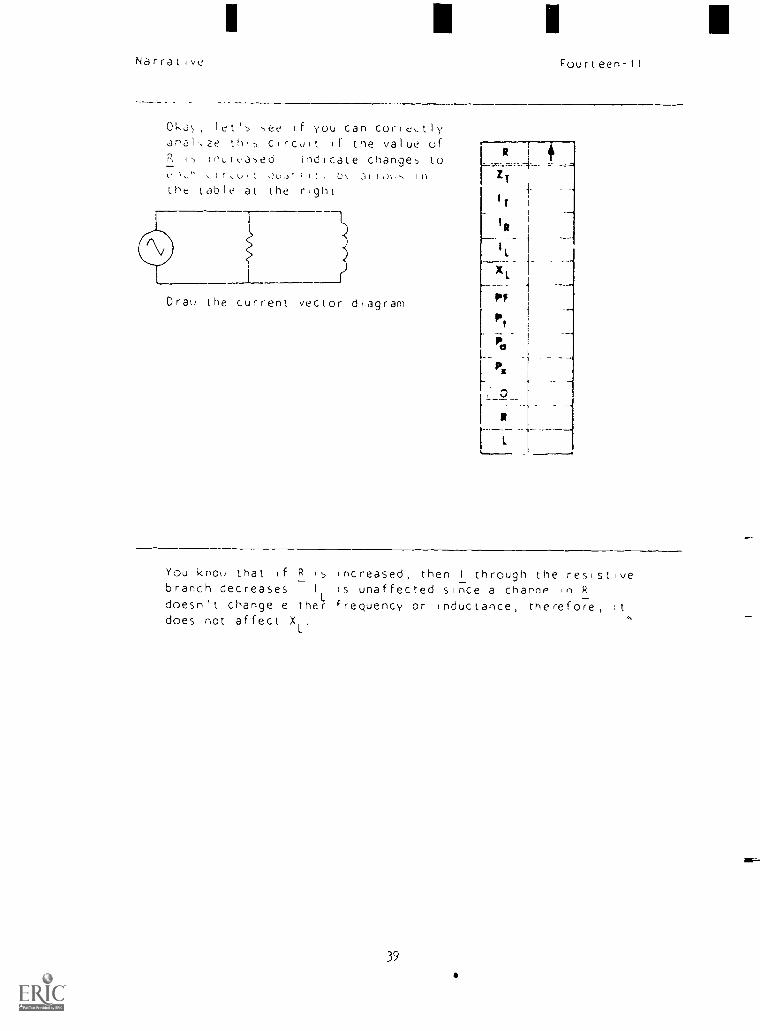
Oka, let's -,ee if you can coriectlyanal\ze th.s circuit tf the value ofR is incrcased Indicate changes to
,IC,U.1 ;It. L%
the table at the right
R
/11-
R
xl
Pt
PaP
Pic
1 #
Drau the current vector diagram
You kno\J that if R i increased, then I through the resistivebranch decreases I is unaffected since a channp in R
doesn't change either frequency or inductance, therefore, It
does not affect XL
39
Nar rat ve
1
R
Fourteen-II
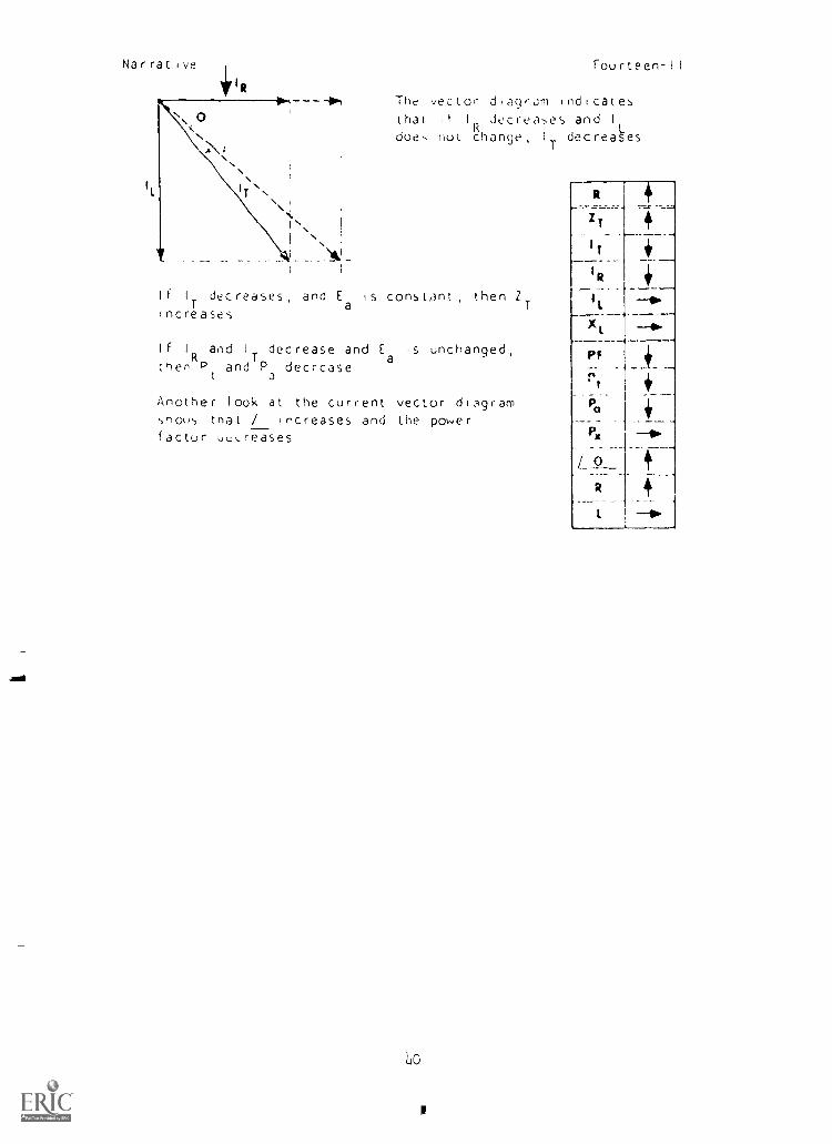
The vector d agram 1 nd cat es
that 1 I Jecrea-,es and I
doe, not change, IT decrea6s
I f I decreases , and Ea is constant , then ZTIncreases
I f I and IT decrease and E is unchanged,(her
RPand P decrease
a
a
Another look at the current vector di:Agramflo%)s that / ncreases and the powerfactor ue,reases
o
Narrative Fourteen-II
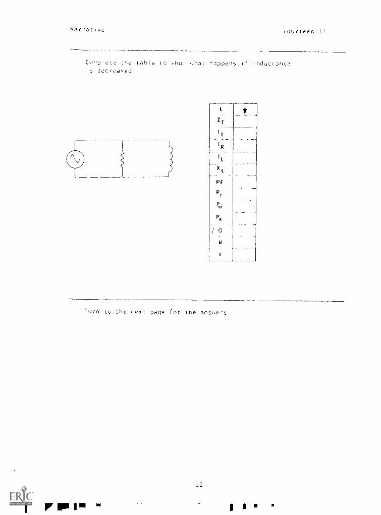
Cor-plete lht table to ho uhat happen:, if tnductance1, oecrea,,ed
I.
ZT
I
IR
X1
P F
Px
0
R
I
Turn to the next page for the ahsuers
11
I r IPP I a 1"' 1 I II I
i
Narrative
Ar,',,ren,
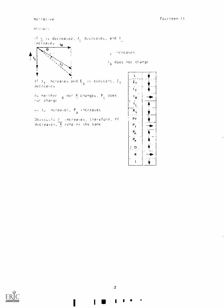
It I _ 15 decrea5ed X decrea5e5, and I
L L
IRircrea5e5
1
t
II.1 ncrea,,es
1
i
I
I does not, change.IT , R
'N" *
. I
Ai.
and Ea
1,, constant, ZT
IF I
Tincreae5
decrea,,e,
ZT
IT
;), neither IR R change5, P doesR t
IR OPr,ot change
increase,-,, P increasesI' a
Ob,/iou,Iy / increase5, therefore, PF
decrease,,, R remains the same
.2
I U
IL
XL
PT
Pt
Pa
R
L.., i
Fourteen II
1 Narrative Fourteen-II
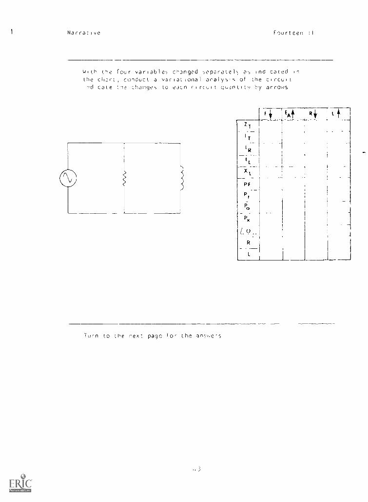
WiLh the four variables changed separatel (-2,, indicated in
the chart, conduct a variational analysIs of the circuit
Indicate the change, 10 each circuit Quantity by arrows
-TT
I
I,K
P x
/_0R
l
Turn to the next page for the answers
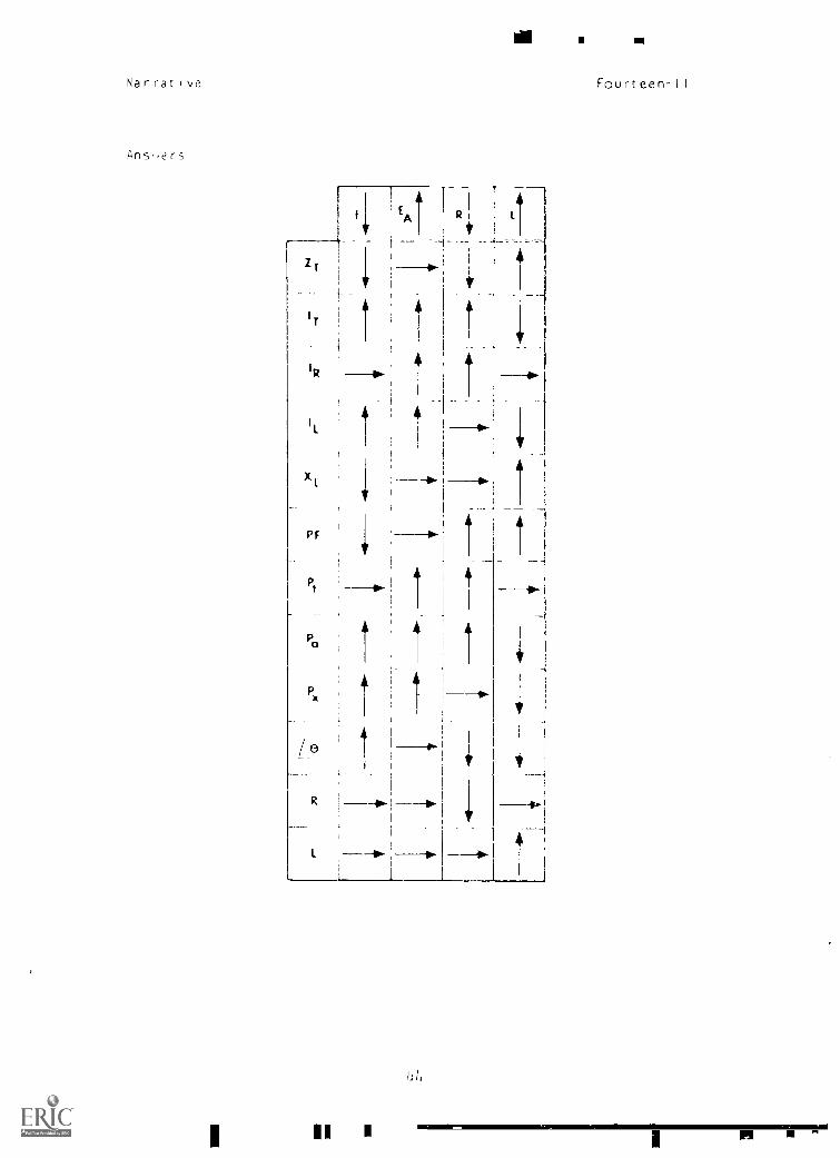
Nar rat 1 \,e Fourteen -II
Ans,ers
Zr
I T
IR
PF
Pt
Pa
Px
0
R
1111=IiNIMI11,PI
P I Fourteen-II
PROGRAMMED INSTRUCTION
LESSON I I
Variational Analysis of RL Parallel Circuits
t-5,011, ot i.iil oe;torm 3 vJri01 ional analysis on parallel
RL t.ircuit to determine \hat effect changes in frequency, source
volta.:e, resistance, ane inductance have on the circuit valuesYou remember from past lesson: that a variational analysis of thecircuit values consist> basically of choosing one quantity as an in-
dependent variable and documenting the relative changes of all other
value-, 35 the independent variable is changed
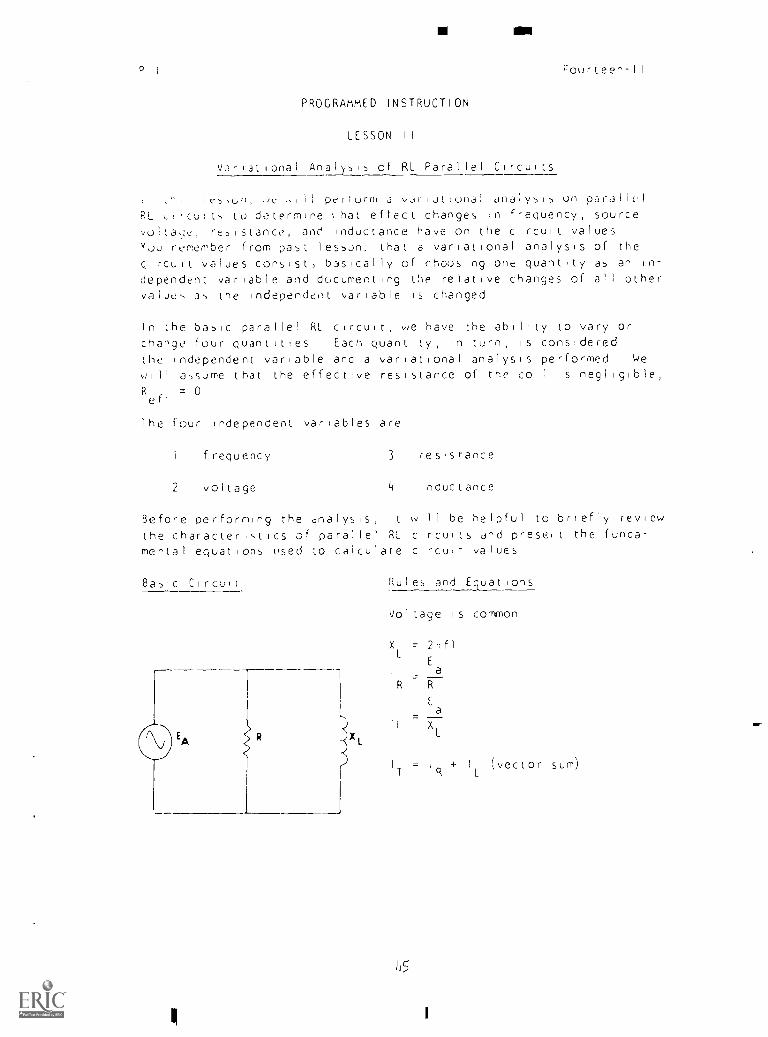
In the basic parallel RL circuit, we have the ability to vary orchange four quantities Each quantity, in turn, is considered
the independent variable and a variational analysis performed We
wi ll assume that the effective resistance of the coil is negl igible,
R . 0eft
the four independent variables are
frequency
2 voltage
3 resIsrance
4 inductance
Before perfbrrling the analysis, it will be helpful to briefly review
the character tics of parallel RL circuits and presei t the funda-
mental equations used to calculate circuit- values
Basic Circuil Rules and Equations
Voltage is coffnon
X = 2-1f1L
Ea
I =R R
Ea
I
. _____
I XL
T
115
+ I (vector sum)L
111
P I Fourteen -II
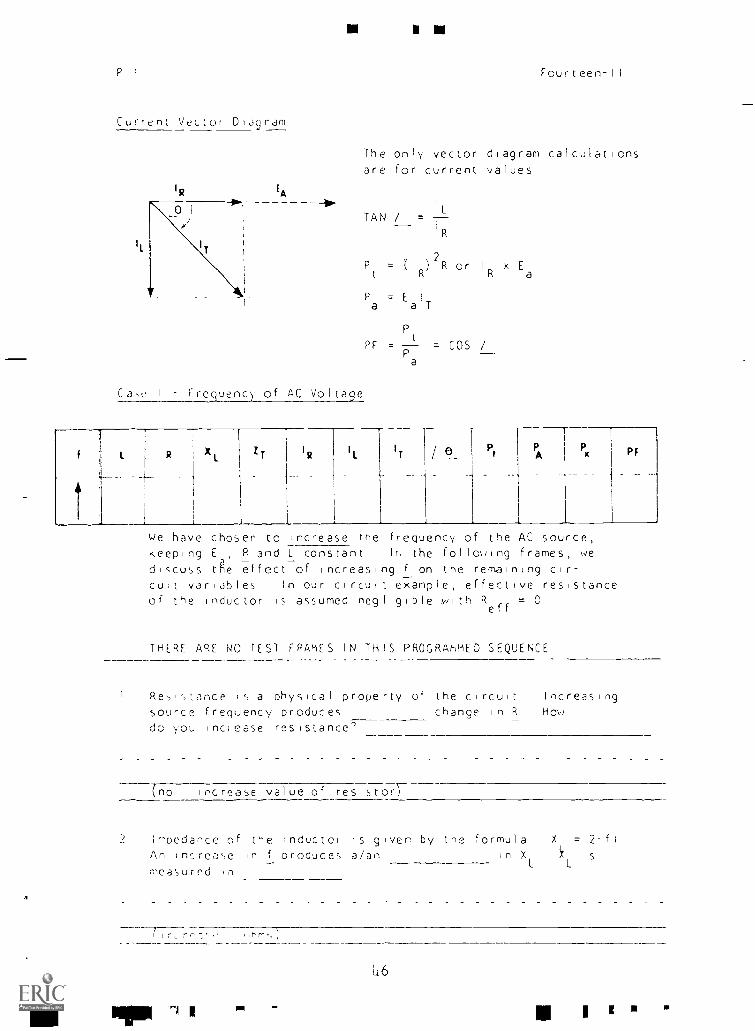
Current Vector Diagram
IL
EA
Ca,c I Frequency of AC Voltage
The only vector diagram calculationsare for current values
TAN / = 7
P2R or 1 x E
a
Pa EalT
PF =t
COS /Pa
f L R XL
ZT
IR
IL IT Pt
PA
Px PF
4-- --1_
1,1e have chosen to increase the frequency of the AC source,keeping E R and L constant the following frames, we
adiscuss the effect of increasing f on the remaining cir-cuit variables In our circu t example, effective resistanceof the inductor is assumed negligible with R = 0
eff
THERE ARE NO TEST FRAMES IN THIS PROGRAMMED SEQUENCE
Resistance is a physical property of the circuit Increasing
source frequency produces change in R How
do you nclease resistance'
(no increase value of resistor)
;''Pedaoce of the inductor is given by the formula X = 2-fl
An increase in f produces a/an in X
measurod in
Pi
L16
IP I 111
I
Fourteen -II
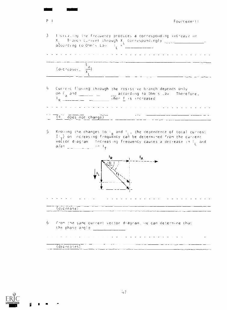
3 lilLrLuilny the frequency produces a corresponding increase inXL
Branch current through XLcorrespondingly
according to Ohm's Lao IL =
Ea\(di'creases --i
XL
Li Current flooing through the resistive branch depends onlyon E
aand according to Ohm's Lau Therefore,
I
R,hen f is increased
--TR, does not change)
5 Knokiing the changes to IR and IL, the dependence of total current(IT) on increasing frequency can be determined from the currentvector diagram Increasing frequency causes a decrease in 1
Land
a/an in IT
EA
(decrease)
6 From the same current vector diagram, ''e can determine thatthe phase angle
Tdecre3ses)
in
117
P I Fourteen -II
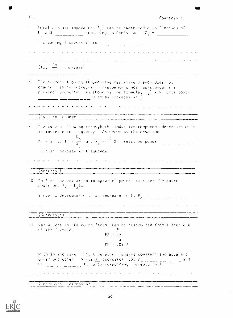
Totl ,,rcuit impedance (ZT
) can be expressed as a function ofEa
a, td according to Ohm's Lau ZT
=
Increasing f causes ZT to
Ea
(IT'I '
T
inLrease)
8 The current flowing through the resistive branch does notchange ( ith an increase in frequency since resltance is a
ph,,,Ical property As shown by the formula, IR x R, true poweruith an increase in f
Tirw, not change)
9 Lurrent flouing through the inductive component decreases with!ncrea-,e in frequency As shown by the equation
E2
XL = 2 IL, I = and Px = I XL'
reactive powerL X
a
L
lh an increase in frequency
(decrease)
10 To find the variation in apparent power, consider the basicequation, P
a= E
a T
Since I decreases ith an increase in Pa
.rd rcasesre
II Variations in the power factor can be deter -mined from either oneof the formula,
PF La
PF = COS /
1,slith an increa-e f, true power remains constant and apparentpry,er decrease ; Since / decreases COS / andPf for a correspond no increase in f
( increases ncreasns)
LF
I
P I Fourteen-11
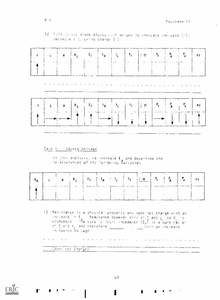
12 11 in the blank blocks ith arrous to indicate increase (1) ,
JeLreo,e t ), or no change ( )
l'-
f L R
..:
l't
il
Xl,
ZT
IR
IL I IT
I
/ 0 PtPA Px 1 p r
1
1
!!
L R
,
XL
ZT
1
RIL IT Pt
AP 11
Px P F
Ca,e II Source Voltage
In Lhik analysis, re ncrease E and determine therelationshIps of tha follov,ing
EA
t
L R
_
ZT
IR 1
IL
I
I
I
IT Pt
PA
1
Px 1P F
r-
13 Resistance is a physical property and does not change wIth anincrease in E Reactance depends onli on f and L, so X is
unchanged Tha e total circuit ,mpedance (2T7 Is a comb nation
Or P and XL
and therefore ulLh an Increasein source voltage
(does .-,Qt change)
I
L9
I
P Fourteen-II
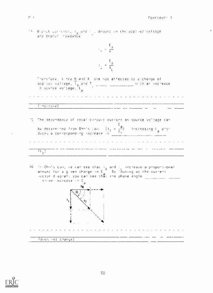
1L4 Bljflh ,,,,f;c,1.", 1
R L
dnd I depenc on the applied voltageand branLh ,h ot dance
Ea
R
E
a
L XL
Therefore, since k and X are not affected by a change ofapplied voltage, IR and 4L with an increase
In source voltage, Ea
(Inc(eJse)
15 The dependence of total circuit current on source voltage canE
be determined from Ohm's Lau, (1T Z
= _a ) Increasing Ea
pro-
duce-, a corresponding Increase in T
16 in Ohm's Lau, ue can see thatI and I Increase a proportional
Lamount for a given change in E
RBy looking at the current
Jector d,agram, you can see th2t the phase angle,tn an Increase In E
IL
a
IR
A
rdues not change)
5o
P 1 Fourteen-11
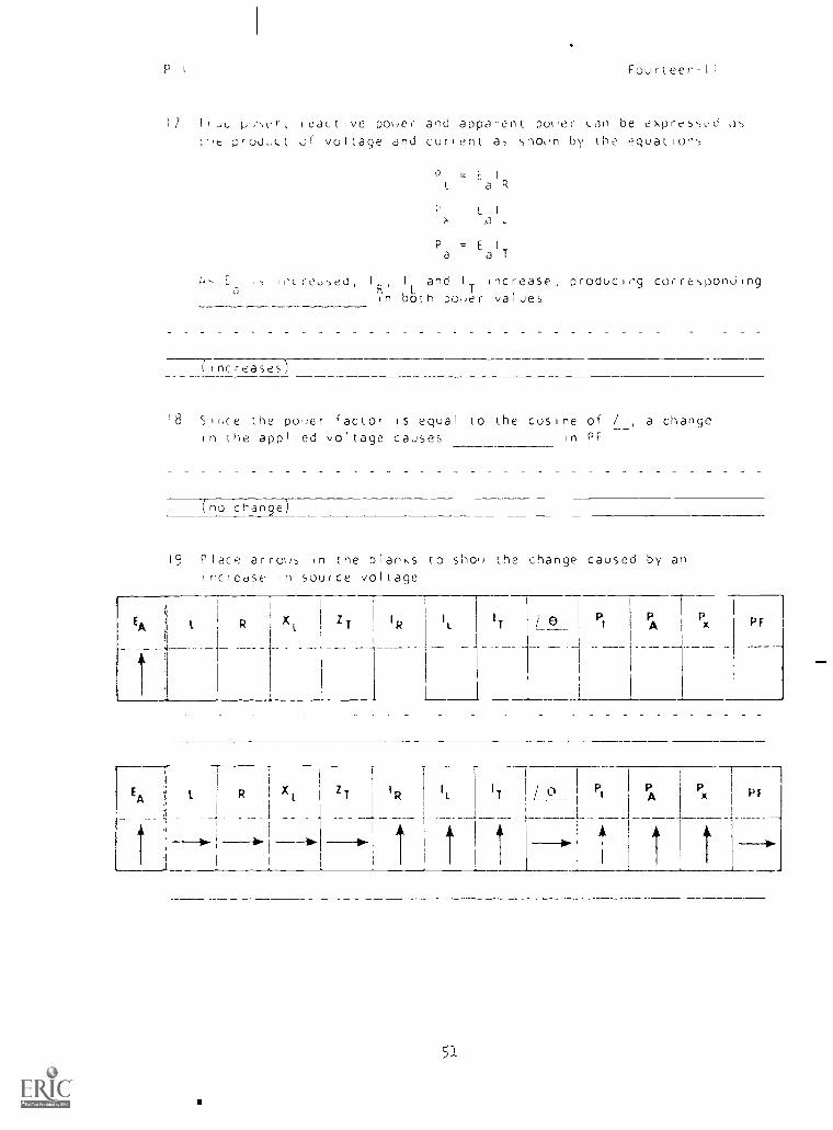
1/ I,JL p-,er, feactIve pouer and apparent poker Lan be expressed 35
''e ;)Ot.I.ILl Of voltage and curfent as shorn by the equations
P = E I,I a rs
t I
x ,a L
P = E 1
a a T
A.,, E
ais H-treused
I
RI
L
and I
Tincrease, producing corresponding
in both po,er values
( Increases)
18 Sir.ce the poser factor is equal to the cosine of / , a changein the app1led voltage causes in PF
(no change)
19 Place arrous in the blanks to shoe the change caused by anincrease in source voltage
EA
it
l R L Z T I R ILIT / ©_ Pt P
APx P F
EA i I
a
R XI
ZT
IR
ItIT
1
1
t 1
L °Pt
f
A x 1 P EP
k1 1
5-1
P I
,.,,3:,,c; 1 1 1 iJnLt
11
R l I R 1 XL
i
ZT
I
Fourteen -II
RIM=
2U
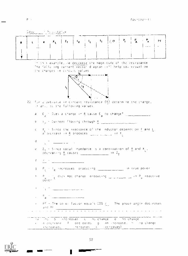
In tnii, example, iie decrease the magnitude of the resistanceThe 101 la ing current vector diagram ii ill help you visual 17ethe change; in c,rcult values
I , 1
,,v ,
I
1
.. ,
A4.1_
J Jt<le,),e in circuit resistance (R) determine
I an,, tL, the folloi,ing values
a E
aDoes a change in R cause E
ato change2
b1
PCuirent flowng through R
the change
X Since the reactance of the inductor depends on f and L,_a
LJ(fcrease in R produces io X
L
d i
e 2_ Since total impedance is a combination of R and XL',1
decreasing R causes in 2
9
T
P Iincreases producing in true poker
L R
P I do,?,, not change producing ,n Px
reactivex
00%/er
I
T
Pr The poi e, factor equals COS /
and Pr
The phase angle decleases
5 increases c no change d no changera dc-ease , decreases g an increase,
-,creases, iincreases k increases)
no changb
52
P I
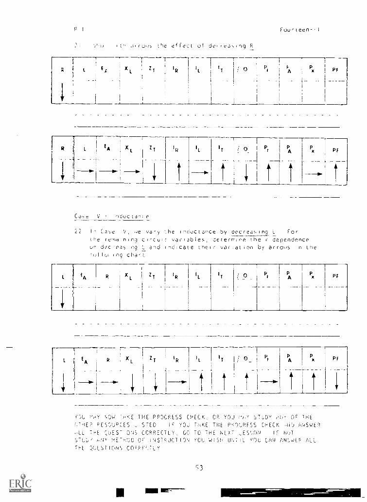
urrous the effect of de,frasng R
Fourteen-li
XL ' zT
I
RI
T
R 1EA X Z
T1IR
I 1 IT
T
1
I Pr
PA
Px
---10-
PF
Ill
Cae IV Inductance
22 In Case IV, vary the inductance by decreasmng L For
the remaining circuit variables determine their dependenceun dec-easing U and indicate their variation by arrows in the
!u1 l51 ing chart
1 EA R 1 X 11
l IT °/_ _ _
Pt PA
Px PF
I
1 It E A
I
1
I
R XI
_
1 Z T
I
1 RI
1
_
IT I
I
/ 0__
t
Pt
-4
PA
_
l
Px PF
_
YTAJ Nh NOW TAKE THE PROGRESS CHECK, OR YOU LIAY STUDY OF THE()THEP RESCUDCES LISTED IF YOU T/0',E THE POI.PFSS CHECK Ni)A ANSWER
ALL THE QUEST'ONS CORRECTLY, GO TO THE NEXT LESSON IF NOTSTuD iNy METHOD OF INSTRUCTION YOU WISH UNTIL vOU CAN ANSWER ALLTHE QUESTIONS COFPP,TLV
3
Summary
SUMMARY
LESSON 1 I
Variational Analysis of RL Parallel Circuits
Fourteen-11
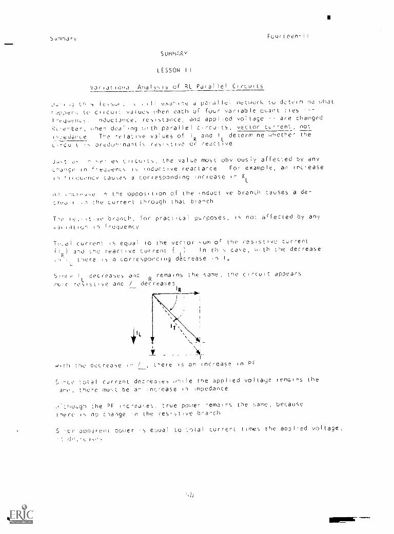
,,,; fr, y 1,,5QH, ,, , ,Ii cxar,ine d paid Il nel, ,,Ork [(,) determine uhat
id;t,-)en5 to circuit values ohen each of four variable quantities
trequenL), indu ctance, resistance, and applied voltage are changed
R(ieter, ,hen dealing oith parallel circu ts, vector current, not
It'oedanLe The relative values of I
R L
and determine uhether the_
Lircuit i5 preaominantk resistive or react ive
Just o5 in se,e5 circuits, the value most obviously affected by any
Lhange in frequencN 15 inductive reactance For example, an Increase
,n ti(quency causes a corresponding Increase in XL
A,1 irftir-Jse n the opposition of the inductive branch causes a de-
crea ( ,n the current through that branch
The ie,istive branch, for practical purposes, is not affected by any
variation in frequency'
Tri(d1 current fS equal to the vector sum of the resistive current
(1 ) and the reactive current (1 ) In this case, ulth the decrease
,nR
i there is a corresponding decrease to I
L T
since I decreases and 1remains the same, the circuit appears
rix,le resL istave and / decreases
,1 L
,
v ,4
,iiith the decrease in / there is an increase in PF
Since total current decreases oh,le the applied voltaye remains the
ame, there must he an Increase in Impedance
1though the PF increases, true poorer remains the same, because
there is no change in the resistive branch
Since apPareni norrer is eoual to total current times the applied voltage,
I ' . ri `. r L 3,1',
,, b
Sumrnar,,
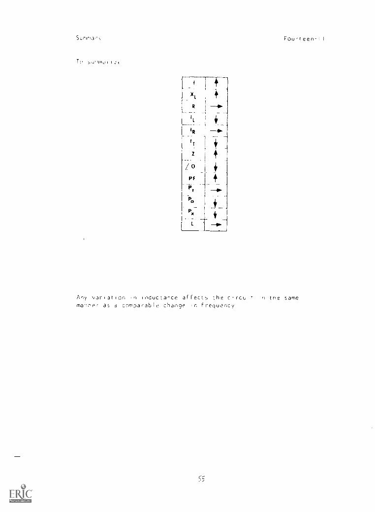
Tu survid f I : (
Fourteen -II
Any variation in inductance affects the c.rcuir in tne same
manner as a comparable change in frequency
55
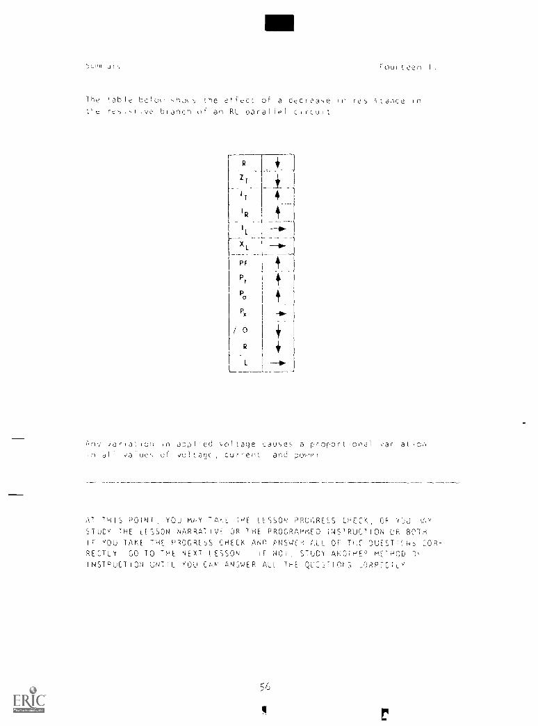
5Lnil JI', Foultcen-11
The 'able bolo ,,ho,5 the eficcE of a decrea-se in resIsLaYce inE'e re-,I,Elv,? branch of an RL parallel circuit
R
I
R
PF
Pt
P,,,
Px
/ 0
R
L
i'.nv iariatIon in appl,ed \-ollage cau,,e a proportional variat,onin al I value., of volLagc , current and pc,-.e
AT THIS POINT, YOU Ml -Y TAE.E HE LESSON PROC,RESS CHECK, OP YOj ,\A''
STUDY THE LESSON NAPRATIVi=. OR THE PROGRAMMED INS1RUCTION UR BOTHIF YOU TAKE THE PROGRESS CHECK AND PNSWE e C,LL OF TIE- OUESTIEN COR-
RECTLY GO TO THE NEXT lESSON IF NO STUDY AHOTHEP mElHOD ")
INSTPLICTION UNTIL YOU Co /'' ANSWER ALL THE QL:SEIOES ..0P,PiCTLY
56
4
NAVPERS 914558-1,3
BASIC ELECTRICITY AND ELECTRONICS
INDIVIDUALIZED LEARNING SYSTEM
l-lODULE FOURTEEN
I_ESSON I
Parallel RC and RCL Circul is
Study Booklet
Bureau of Naval rer,orncl
January 1(3)-,
57

:v. ,, te,
Fuurteen-III
9Ni-5/1E,..I
LESSON In
',l( ' RCL C r
_._.
ICS-,c- \Do I ,(uc, and legit dhow( 01,, rolIatIng
-(..Hvina pd -)ilea RC ,.,Lui
-variaLicmal an)ly15 of parallel SC
circu,1
-sL)IvIc)9 paralltl RC1_, circuits
BEC'RE Ynu START THIS LESSON, PREVIEW THE LIST OF STUDY RESOURCES
ON THE NEXT PACE
SR
2
LMT Di- STUDY HE SOURCES
LEON Ili
41 r
( le`,10'.1 10Li HVC.11, pi Of ch (Jo', rIo
,,,perienLo and prefer,nct,,, am\, or all (11
5L-;. 5C,'KLE1
Na P
r u II on
S
"Bac,:c Eec I rn Iv, Al lIrnut I aq Cuircni "
cL)nuatrr/a I E1ectron;cs Burr au of Naval Per,,onnei
11 0 0 C U S Govefnment PrInLing Orfice, 1965
Nn.) STUDY ,dlY OR ALL OF THE kCSOURCES LISTED 'kBOVE YOU MAY
1,,Yt PPOGPESS CHELK icr ANY TI Mt
Naridtivu
NARRATIVE
LESSON 1 11
Pa1,3111 RC and RCL Cr,cu'ts
Si)Iving Paidl lel RC Circuits
Fourteen-111
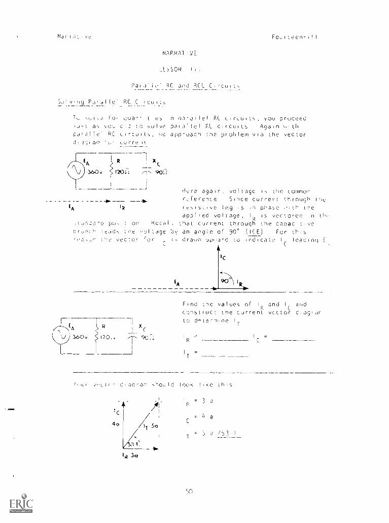
To: s,i,.' 10; guan' ties in pa-allel RC circuits, you proceediust a',, you did to 5olve parallel FL circuits Again uith.,arallel RC circuits, SC approach the problem via the vectordi 3giam 'of Lurre it
!n1
RX (
360v 1203 '-'t T Sflp(2i
EA IR
Hero again, voltage is the commonruference Since current through theresistive leg is ip phase orth theapplied voltage, 1 is vectored in tb'
itdriJare pu,ition Rccal 1 that current througl the capacitiveordflLh leads tne voltage by an angle of 900 (ICE) For this
Or vector for 1
C
1,, draun upward to indicate 1
Cleading E
EA
E Xc
C V ) 3.50 v j 120 . . -- 9.C....-
1
Find the values of I
Rand 1
Cand
construct the current. vector diagidrto d,,termine IT
1
R= 1
C
=
____J 1
T=
T'oui .,,cir - diaoram should look like this
'C
40
2
"I 1'
R 3a
= 3 ,-,
r = b a
= 5 a /53 1
Narrative Fourteen -111
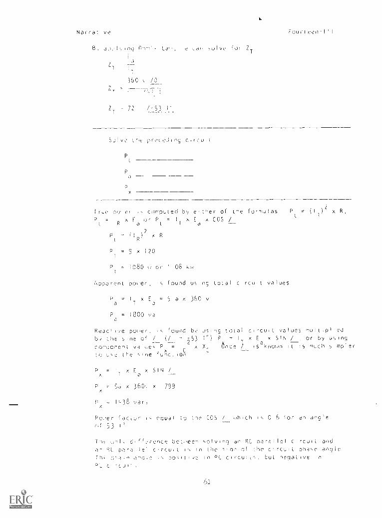
B, a1,,Int] Ono', La,' e can -)olve for ZT
l
J
L
T
a
1
360 \ /0----,
i ,l,:
zT " / 53
Silve the preceJing c,rcult
P
Pa
2
x
rrpe pry er ,,, computed by either of the formulas Pt 2
= (I )
2x R
P =I xEorP=IxExCOS /t R a t T a
P = (IR)? x R
P = 9 x 120I
P = 1080 w or I 08 kw
Apparent poser, s found using total circuit values
P = I x E = 5 a x 360 va T a
P = 1800 vaa
Rejc, [Ye po,et, Is found by using total ci-curt values mutt plied
by' the sine of / (/ - -53 1')P=I xExSiN / or by using
conuonent values P = IC x once isaknown it is much simpler
to use the sine function
P = I x E. x SIN /x, T a
P ' 5a x 360,. x 799x
Pxt
- IL38 var,
Poe racturf 53
coual to the COS / which is 0 6 for en angle
in,2 ,,,nl, d,flft.,ronce be.,een ,olvinq an RC parallel circuit aad
an PL parallel clrcu,C is in the c-inn Of the cIrCuli phase angle
T`--,,, DH.1,0 .`'Olt' l', D0:11 1,/c In DC circuits, but negative in
°L c rcui ,

N3r
P: I" PubIei
e R 80..
3
I
Fou,-(I I
77 =
Ea
X =
I pr ub I due-, he ci icu! Jpp#?ar more resist lyeflre Lapdc
360w
X i
25 6 /-70 5
160
Ea
I =
1 =T
Z1
62
I
Natra;.IA'r Fourteen-II I
2
5 E 120
IT 5 J /53 1_
ZT 24 7-53 1
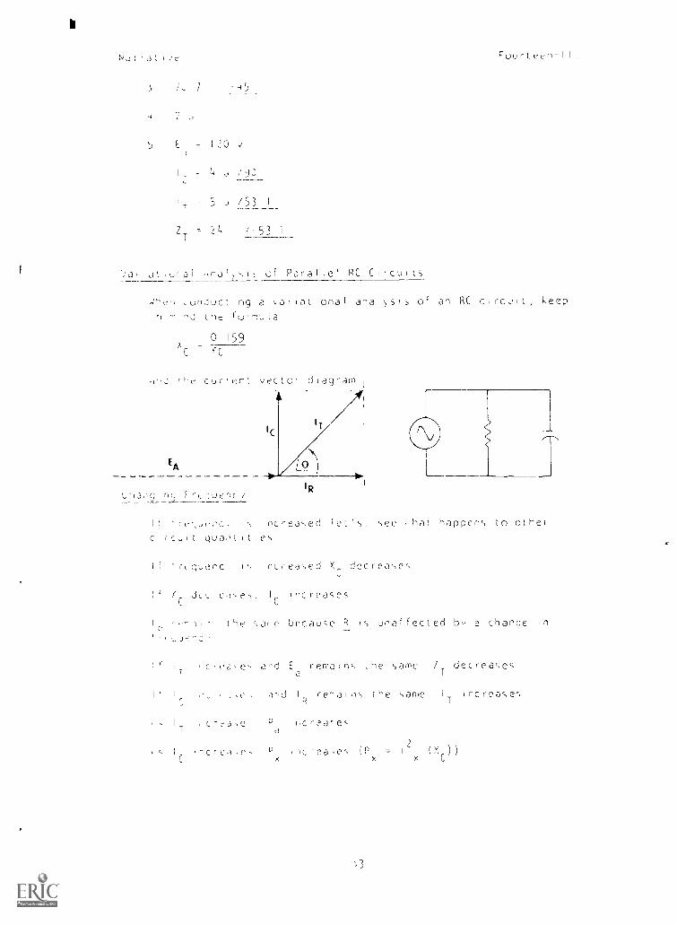
c)f- Paralle1 RC Circuits
Lunductinq a ,arlar,lonal analysis of an RC circuit, keep
ninJ tne fulnula
C
159
C
nJ cur.r2nt vector diagram
IC
EA
IR
[ncrea,,ed ha t happens to other
c,rc,[t puaiLes
quenc, 1,, 1 r,re;)sed X decreases
J( I Inc reosesC
He e because R is unaffected bo a change in
ad Ea
remair,,, the sans ZTdecreases
and cerai,ls he sane I incrcase',T
1 C n0e P ircrea-e:a
2A c fl.0 e iea (P - 1
( X ) )
Narraziye
7,
/ 41
7 / / 7
,
# I
/
4PH
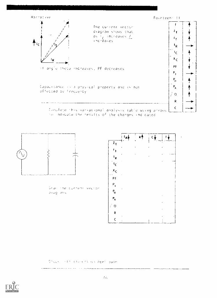
if any le L(21.3 increases, PF decreases
The current vector diagram shoYs that
as Ir increase ,
/
increases
CJI)L3LILOfiCt' I
, 3 physical property and Is not afiected by frequency
Fourteen-II I
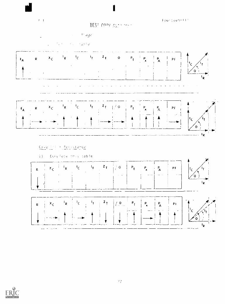
hl,,lete 1hp, variatio nal analysis table using arro,s inalcate tne res-ults of the changes Indicated
U' dr Int, Curren; vector .tliag'xl,
f 1 4
IT
IT
I R
IC
X C
P F
P t
Pa
Px
/ 0
R
C
EA
Z 1
IT
xc
P r
Pt
Pa
Px
/ 0
R
C
lih ,-) - r'. (jn ,-;?Xl Dag('
4
f --111.
4
i 4
----a t t t
'0
(!),-.,ei
I R
4 ie
4 I.
BEST COPY A.'" '. ",Fcuiteen-III
Etti Rt Ci fi
i 1 4
R i
ZT ---0-
p 4, __... ,i
/_ o_ 4 + 3,
a ----0. 4 ----I. --..L c --a. 1... + 0-
IR
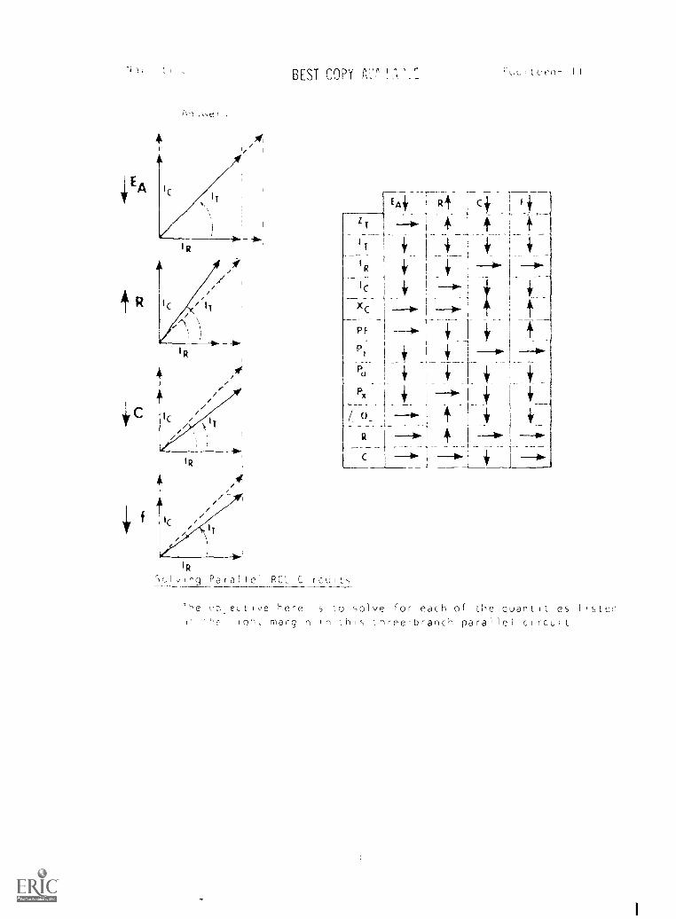
Ing Para I lel RCL Circuis
L,beLLI,,,e here is 'Lo solve for each of the quantitie5 listedloH, margin in thi,, ihree-branch parallel circuit
1
Nar-attve FJiuitt en-I I I
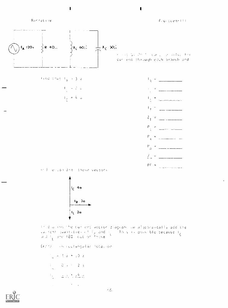
120v R 40.. x Xc60P
I
Lu' 3
if
J e a Jra tne,c vect()rs
IIC
40
, t I
C u t Ct tuugh 3u1( f)r53t)L11 and
IR
=
=T
7 =
P =
P =x
PF =
Is
,Ji
Ji i
di.J
run'
I
L
in') 'He
]uai)titic,
J-c IBC
IR 3ca
.icctor
I andC's-e
dug anI ThisL
,ie
is
algebraical I add
po,,,Ible because
the
I
C
2°
cu-
(itJt
ent
,if
,)f
I,LtanquI.31- 'ota(wn
" ,0 a
I .1 2 a
114 a
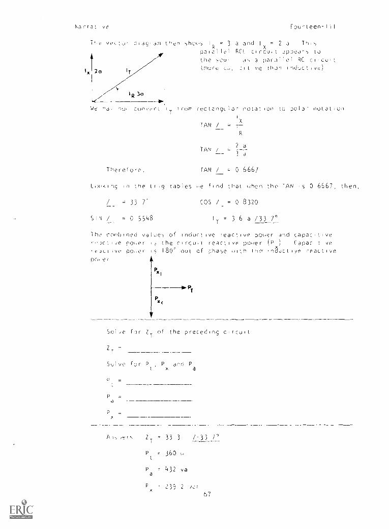
Narrative Fourteen-III
The veto, diagiam then sho,s I = 3 a and I = 2 a ThisX
paraR l lel RCL circuit appears tothe soul as a parallel RC circuit
Ix 20 r
cmore L, :Itive than inductive)
IR 3°-0.
,./ 7L3' nor convert IT !rum rectangular notation to polar notationI
Therefore,
TAN / =X
7__R
TAN / -2 a---3 a
TAN / = 0 666/
Louking in the trig tables ue find that hen the TAN is 0 6667, then,
= 33 7- COS / = 0 8320
SIN / - 0 5548 I
T= 3 6 a /33 7°
The combined values of inductive reactive power and capacitive-)ctlie poser 1, the circuit reactive poser (P ) Capacitive
fc=ak-tive Doer is 180° out of phase u -tiththe' auct ive reactivepok er
Pxi
Px(
Solve for ZT
of
ZT
Solve for P P
P =a
P=x
PT
the preceding circuit
and Pt x a
/1,1-, ,t: r `-, ZT
' 33 3 /33 7'
P = 360t
P = 432 vaa
Px
23S 2 i,57
Fourteen -I II
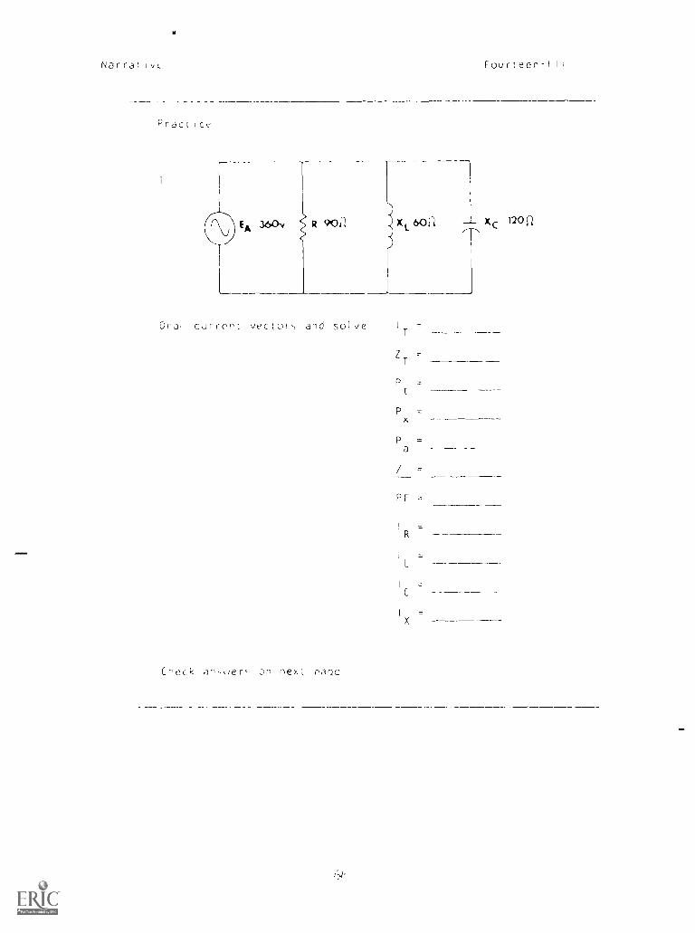
Dra, current vector, and solve I
C'-seck ,Ifl,,,ier= on next rr:ic
ZT
P
Px
P =a
/
PF
R
C
I I I I I
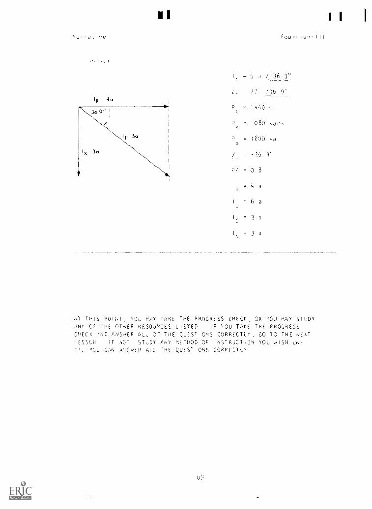
Narrative Fourteen-III
IR 4a
.5 9'' ,!
N IT 5°
I, 3a
I 5 ,I / 36 9°
iT /2 /36_2Y
P = 14140 \,
t
P 1080 \,ar',
P = 1800 vaa
/ -36 9'
PF = 0 8
I = Li aR
I = 6 aL
I
C= 3 a
Ix = 3 a
.\T THIS POINT, YOU MAY TAKE THE PROGRESS CHECK, OR YOU MAY STUDYANY OF THE OTHER RESQU'',CES LISTED IF YOU TAKF THE PROGRESSCHECK AND ANSWER ALL OF THE QUESTIONS CORRECTLY, GO TO THE NEXT1ESSON IF NOT STUDY ANY METHOD OF INSTRUCTION YOU WISH UN-TIL YOU C,\N ANSWER ALL THE QUESTIONS CORPECTLY
I ii1RDOE,,,MME0 INS1F,ULIION
LESSON I II
LH RC and RCL C
H L Pr 0 'Ai ,ILJE r:LE HtS NO TEN FRAME_
FL)u f t
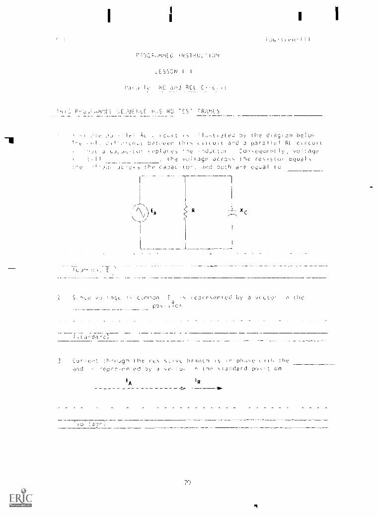
11t1 Cu l I. I I I a led by the d[agram be uTre , n bet'een t N i Cu i t and a pa r le RL C I rcul t
a cajutur npIaue he rnductui Cof,-,equent ly voltageI
the vintage acro-,,, the re,, is toi equalta a N a c a ,D the capac L to r and both ane equal o
R
XC
1, cc.,mmon E represented by a vector in the
poa
1 , icr
landard
3 Cur et hrough the rtsI,,,tivu branch is In Dhar,c ' th the
and i repre,e.nied by a ce ui n the ,,tandard pc), t on
EA I R
(vol aq()
70
P I Eourteen-ll I
I, Lan LJ IuIaiJ o',
J J'iel kt_ or RI, t_ircult-,, the circuit value to vector for
In the purel,, capacitive branch, current
90voltage by
ead,,)
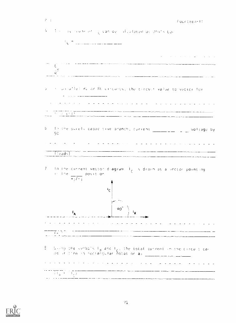
7 In the
Ine
current vector diagram 15 dra\'n a5 a '/(t'ClOr pointing
EA
position
9O') I
R
7-( 4-
U.Inf] the ,vrnbol,, I an I the total current ,n the circuit car,P C,r ,:.en in rcelariquiar notation as
)
r
7].
p
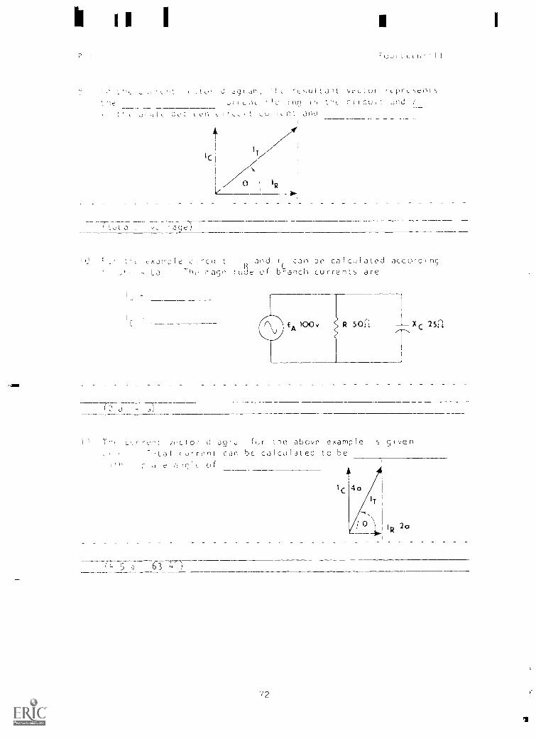
I Jr,,, r,,u1 I pr,
:flr , , nsj III t.h, CIICU. nd
L II II L ; ; ,-L11 Ilnl jntl
ICI
/0 IR
393,i
112 JIple circuit IR and lc can be calculated according
- La The ragniLude of branch currents are
C9 EA)OX) R 50cZ Xc 251,
( a , 1J7----
I l T mn c c d ag w fl(,,r the above example is given
current can bc calculated to beCl !_ f
fL 5 a 63 L")
72
?olJr Lc t. 1
; .11 I mp,..dancee r I l I N y
,u1, t, La, fui total11,11
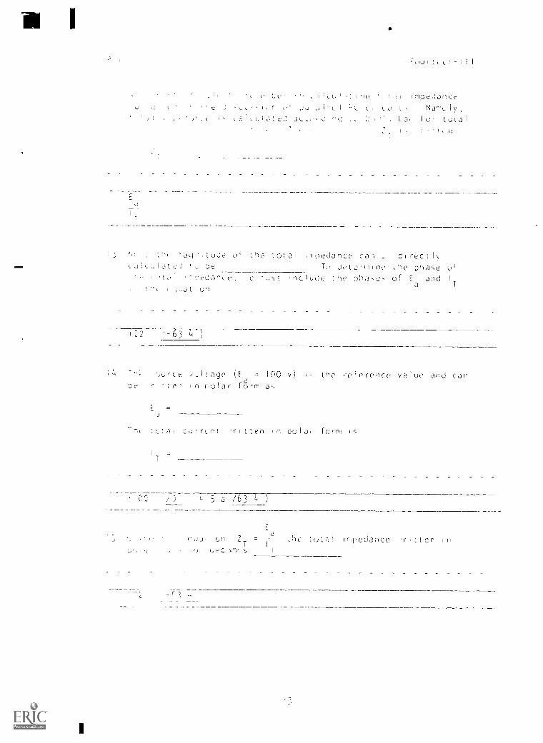
°J, h- I.Uje of the total in pedance Can. L dl reef Irji- i.lOteJ ' To Jet cf ne , he phase of
tedance, e `lust ,nc lude he of E andLit iurl a
t22 1-64-147
CC /.1!ope (E = 100 v) the reference value and canDe rite, in riolar form at,
cur rcnt r I t ten I in no 1 of farm
7 5 a /63 4 )
,cdut Z_ = ,1)C to a l IrlpCdanCe 'ripen()
P I
I
Four,eer-I II
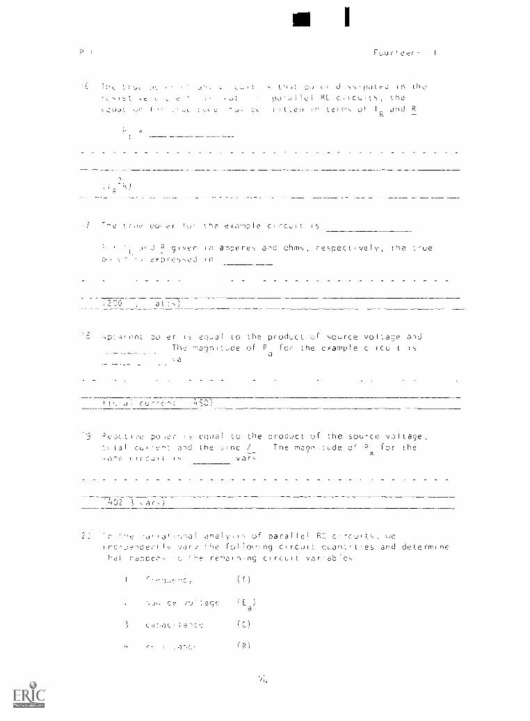
1,, pu fii,,IpdteJ in the
1' poi,11e1 RC ciicuit, thec.,;uail,fl I L r S U 1,c21 :0 erf-,),., oi 1 and R
1,3
Th,e er lur the example circuit is
Dr, c
L 0, J P given n ampere,, and ohms, respectively, the true
'txPre')-,ed in
atti
kp:areet pu er Iequal to the product of source voltage and
The -)agnilude of Pa
for the example circuitfa
CU'rCn: 1150)
19 ''ti.aLLI.,e po,er is equal to the product of the source voltage,
fal current and the ;Inc Tee magnitude of Px
for the
circull vary
77402 3 ,ar,)
2: In "e rjr at i'mal a-ialyi,l; of parallel RC ts ueiedo,iende 1 var) ;he fol louing circuit quantlues and determine
CdI rac,,ecfl, renaining circuit variables
(f)
2 cc :olfage I E )
a
3 cahacilahce
iar-ico (R)
7)1
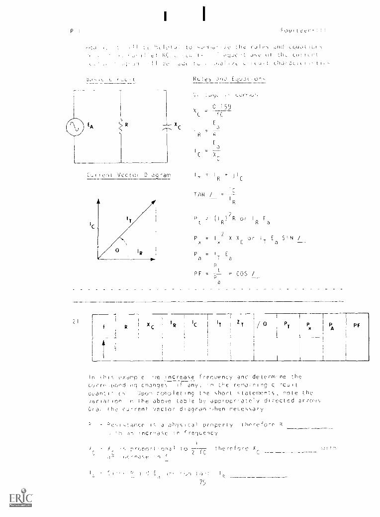
P I Four e'en- { I I
I h 1-1, I r!,; Lo , the Cu I nd Lqunl I Cif
fof e kC l equcr t use or tllr cur r 11
1 1 107' 1 , 1 L i r c U 1 1 c]1Jr3C;r 1 -
UrI
S
R Xc
Cu r f en t Vetter D laq ram
IC
Rules 3771 Equ,:it. ions
0 I
XC=
fC
R
J=
C X
TAN ,/
+R C
C
IR
( I )
2R or I Ea
a
Px = I
2X X or I E
aSIN /
E
a a
PF = t COS /
a
21 Xc I
R IC IT ZT PT Px Pf
this xar-pl e e r nc rease frequency and de terms ne the
c r re ,Dand ng changes I f any, rn the rerna n ny c.rrCUrt
quantItiri, Upon completing the short statements note the
Jar ion in the above Liable by appropriately di rected ar
Dr -)' t he cur rent vector d agran iihen necessary
Pe') ; I"; 3 phys cal property t here fore R
ncrnase n f requency
X s rr,c)(-)r t r ona I ; 0 t he re fore X 1;1 I h2 IC
/j
', Jr J II fl IL U I
, ug 01 H u H a Lne ph) -t Jog
E
Zr = H)e uJtol InpeJjnIc
E
I
1
1,1 a,ld n<r1
I ((2a,IA
,t I 3 13n 3 P
H)urtt.-r)- II I
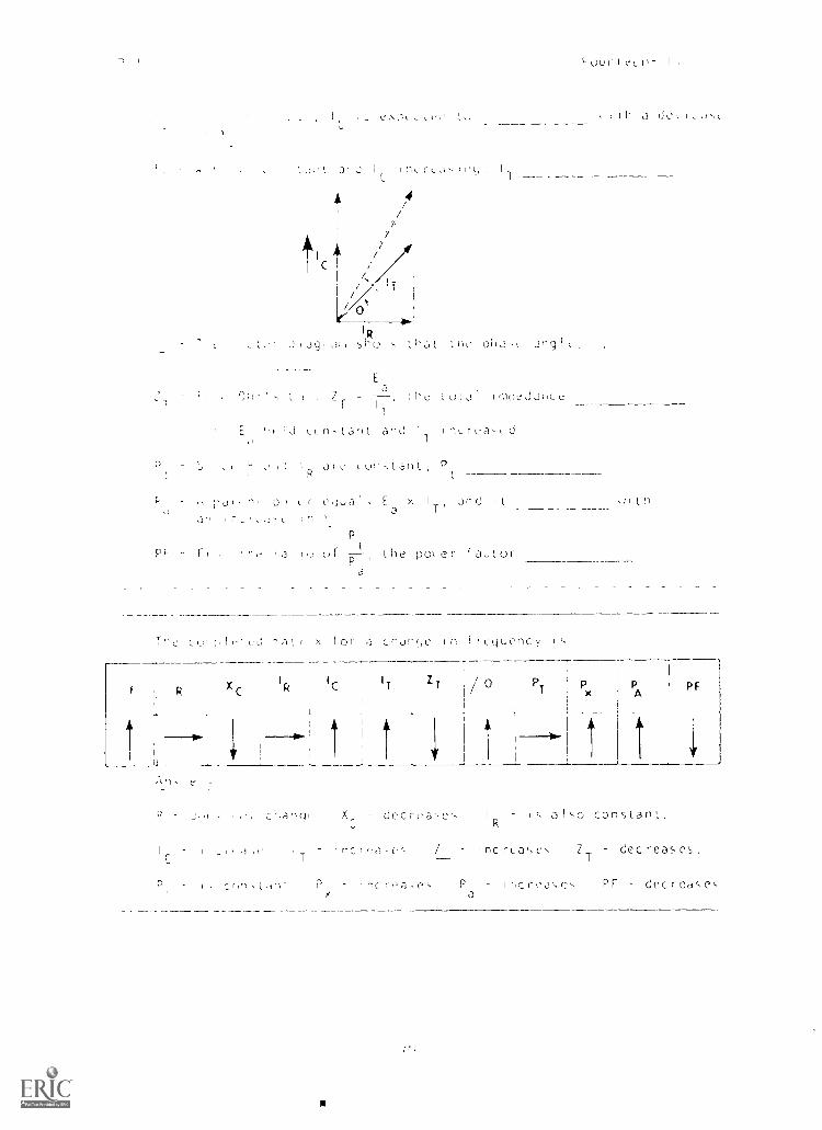
H j
- , 3,) 1 c,JuaI, Ea x I ,Ind ItT'
Cin ,r_r;-; inP
r 3 I I H po e r f 3 t orr
If Ix 1 or ,-, cndnqp in
tr.
cdanq X
I I I 1 .1' I nc. f'd 5 /
Onfl,k.-tn' P
1 cqucnc y 1
PF
I is also constant.,
ZT
decrea5,es.
Pa
ir,orcas,s Pr decreases
.1
R x[
rI
R/[ |/ Z
T 0 PT Px P p;
l''1
1
,
A
1
BEST rnDY
Four !.
EA R X c RI
TZ
T/ G PT P ! p
1AtC3,u' | || 1,,,tance
23 C(_!(!; th!!,
c lc I/ Z T 0
P F
PT
pA
p;
XC
! IC
IT T /0 PT
A p1-
77

P 1 Fourteen-III
ib
IR IC IT ZT I/ o PT P
APF
i
Parade! RCL Circuits
25
PT
1
Px
PA
PF
A !,1 Isle parallel RCL circuit consists of one purely resistivebra"cli, une purely inductive branch, and one purely capacit!veoranch T,,e ba-ic rules for solving parallel RL and parallel
PC circut; )ppi to a parallel RCL circuit
A C
XL
B D
A basic RCL circuit IS illustrated atthe left Voltage is as
XC
in the parallel RL and RC circuits
The total source voltage, E appearsacross branches AB, CD, and`
( (,., )r , ,r E F i
-!7'

, Fourt(ea-11 I
7 c, I
I
L
ulUt', ,e t-Jfl the Lurieht
the three hía0Lt,
La,)
,e branch currents
R 501/ )(c 20c1
7-2 a,
28 E and the current fleeing through the branch are in
pf'a,e, therefore, the vector representing IR 15 plotted in the
IJmdard
(ruS1,,tiVe)
29 Current in the inductive branchsitl,le current ,n the capacitive branch
90
EAIc
096
90R
the voltage by 90°the voltage by
1,ad,)
/9
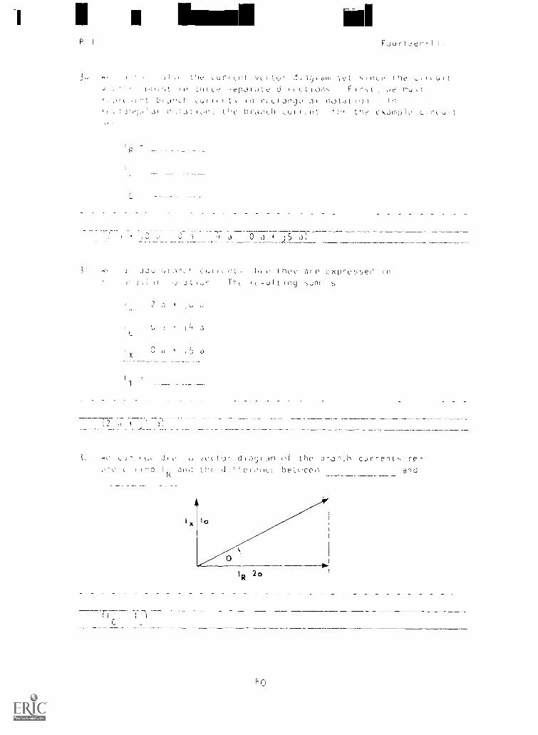
I II bra mdP I Fuu t eerl- I I I
33 tH,e urri vLLU uir LrLv 1 u
, I fl c -t'r)31(1tl: d i on i r nuH,r),h u It f in rt. iae,3t,1,31 not,it 11)1 In
H , , , ; , I a , l ' 3 3 0fl c brinH L u i r t CI' amp I C C I 1 C U I
L
3
3, 0 +
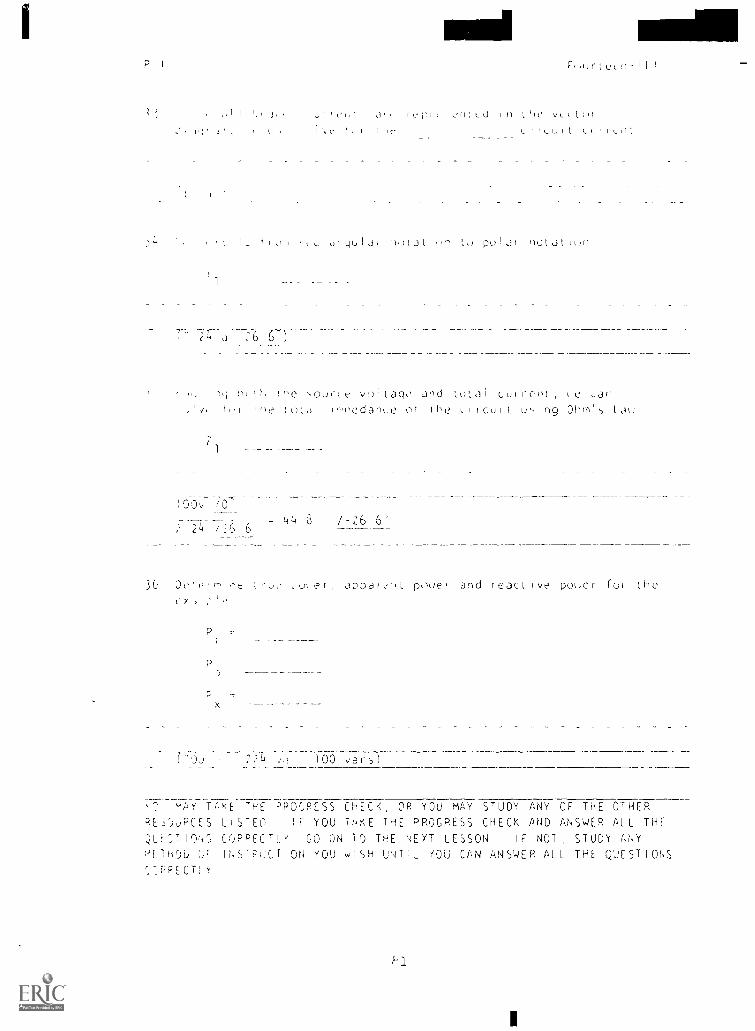
J2u r IIL s, Cur H H H C L-''l' 3112 exPret+I,e0 In1 1 1 j , U n TH LuI1IrCJ I S
2 , I
r,
I% LI 3
0 , 5 aX
d,ay, 3m ti he bran,i-) cur,ent., re-act: C COI I an,J Ho L.1, bet,cen and
riC'
P
1
rflurtccn-II I
Jr I ( U in I VL t()1
r to i t L uI I
I i ' t qu I di ri)',t) t to poi nut ic)n
3t1)
7
IO0v
;
1,
tHe -,ource voltago and 10131 cufccot, \C ,jotutd1 utInedanLe of the c_ifctult
44 8 /-26 6'24 /6 6
P
,v er, appaivnL poue, and react fve pui ;cr 10( the
Du 2)Zi 100 var-D)
AK TAKE THE PPOCRESS CHECK, OR YOU MAY STUDY ANY OF THE OTHERRESOuRCES LISTED IF YOU TAKE THE PROGRESS CHECK AND ANSWER ALL THE
,LE7,T19,13 CORRECTL'' GO ON TO THE NEXT LESSON IF NOT STUDY ANYmETHC)p OF INSTRUCTION YOU WISH UNTIL KOU CAN ANSWER ALL THE QUESTIONSS_RPECTLK
It(urteen-11 I
f,Umm,RY
lE550N 1
Pa JIlel RC Jnd R(.
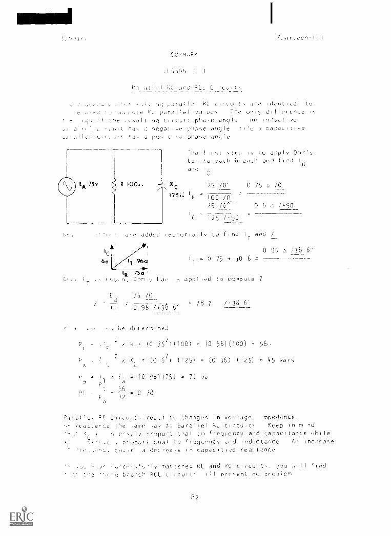
,,Jiji!(-1 LI!',1,1I(`. J' t' 'dent. t.d t
o,C.2 h fate PL parallel v,,,alue,() The onl) dilleiceLe Is
Itj(, f Lhe circuit pho-ie angle Oil induct
,IrL,,L ha, a negatite phase angle hIle a capacitivele, L,,,J'' a 3 positive phas,e angle
J
P
X r
125::
The first stepI
(c) apply OhmI
C,! (o each bianch and find I
and 1
75 /0' 0 75 a /0
=R 100 /0'
/5 0 6 .) /+90
1 =_
C 125 /-.0
d(e adder' \ecturial lv to find i
60 96a
75a I
Ohm's La(! i, appl led to compute Z
and /
0 96 a /38 6'
IT =0 75 + JO 6=
/5 /0
6- 78 2 /-38 6'
'
t be determined
- (lp r h = (0 152)(100) - (0 56) (100) - 56r)
rx X = (0 6') (125) - (C 36) (125) = 45 van,
xa
t 56PT
/2
= (0 96) (75) = 72 va
= 0 28
p.3.a1l,! cc cir,uits react to changes in voltage, Impedance,
reaarce the ,are .ay as parallel Rt.. circuits Keep in mind
, e-set / proportional to frequency and capacitance uhileh`uportonal to creguinncy and inductance An increase
c. cdu,e a decrea,e In capacitiJe reactance
(, -,r; e-,,fully mastered RL and PC clIcult, you hill fInd
a brai-ich PCL circulp oll present ru problem
P2
t'`(
' 1(
Four le eie
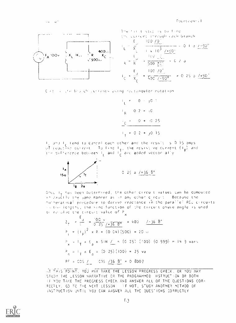
lu 1 Ind
thr0u0 brJnLh
1 I I
100 /0'
3
= 0 I a X-90''_ _400.c L 1 x 10 /riOl-
\ FA i0Ov . X 1K.. R Xc'500:v
R ft 300 /V
Ed 100 /0^
= 0 25 /490'C X /-90c
J
Lid a rnt, using rt._ t,,inge I a r notation
= 0 J 0
I 0 2 + 10
1 = 0 + 10 25
1 . 0 2 + JO 15
I Ji I tend to cancel each other and the result is 0 15 amps
si, raLt iv, cur rent, Tu find I the resistive current ) and
t'ir difference behreen I and I
T'are added vccLorially
15a
IR 2(11
0-_t_ IT ha, been octermined, the other circuit values can be computedIn cr,JC.t Iv the ,ame manner as in any other circuit Because the
mathe,-atical procedure to derive reactance n the parallel RCL circuitsI, tr, 1cng,h\ the sine function of the circult phase angle is used
t, re olJe the circult value of P
0 25 a /+36 8°
Ea vZT
= 400 /-36 8I 0 25 /+36 8°
)
2x R = (0 04) (500) = 20 0
xIT x Ea x SIN / = (0 25) (100) (0 599) = 14 9 vary
P = IT x E = (0 25) (100) = 25 vaI a
= COS / COS /36 8° = 0 8007
,T THIS POINT, YOU MAY TAKE THE LESSON PROGRESS CHECK, OR YOU MAYSTUDY THE LESSON NARRATIVE OR THE PROGRAMMED INSTRUCTION OR BOTHIF YOU TAKE THE PROGRESS CHECK AND ANSWER ALL OF THE QUESTIONS COR-RECTLY, GO TO THE NEXT LESSON IF NOT, STUDY ANOTHER METHOD OFINSTRUCTION UNTIL YOU CAN ky4SWER ALL THE QUESTIONS CORRECTLY
13
N,,PERS 9/AHb-I/A,
6,,S IF ELELTPIE I T`( ,;ND ELEC1PONICS
iNUIVIUU,,LIZED LEikRNING SY5TEn
P4
t-DDIJL E FOURTEEN
LESSON IV
c 0 . R.r-tfLL,,,ncy in Parallel RC Circults
SLU Ei()Okiel,
Bureau uf- Naval Per,,onnel
Januar': 1972
lour t,,m-IV
0,ltro:It\,..
LES'_*N IV
, ti y ,Jn,i 1 e , I f f i d b f i l i i ult."' In IU , my
,.3nal\ / I mg a Pdra I LI LC LirLuit
an ideal patal lel LC circuit operat ing
at. IP, natural re-sonant. ErequenLy
anal yiing a practical rank cIrculL
-cllecL5 of operaLing parallel LC
Lircult.,, at other L[Ici,) ru,,onant.
frequt.:nLy
I'lLe!s ,.:Ing parallel re,,onanL CIr"CuILti
BErl:RE i.JU ST. RT THIS LESSON PREVIEW THE LIS1 OF STUDY RESOURCES
ON THE NE xi P,kCE
t6
routteLn-IV
LlCT C' 11-UH kESOl:RCES
LLSSON IV
t ,,,,,,t LJlnL, ,fl Parallel AC C,r3ult,,
'." 0!e' ii_II in ;Si-, le>,,Jn, you have the option ',I chow,kny,
3 ,5 0 o '.., ,oL.. exetri,nc_e and prLference,,, any or all of le
ST.,I,,,, BDCKLET
L' ,on NC,' r-3' I
ranYicii Ini,truc...11(,)fl
t k...." S. \-3s).
ENPIlw+ENT mTERI,kL
N,oPERS 53LiOG%-lt, "Ba,,ic Electrici,/, Alternating Current
F ,),Ja-wntdi,, of Electronic', Bureau of Naval Personnel
',,ngton, El C U S Government Printing Office, 1965
il\UDf0--L.
S1,Jc/Su,J,c Prentation 'Ronance in Parallel Circuits
YOU 'A, I NOW STUDY ANI OR ALL Or THE RESOURCES LISTED ABOVE YOU
m;Y TAKE THE PROGRESS 'CHECK AT ANY TIME
7
Fourteen -iV
P0, a I 1 Ciiuui is
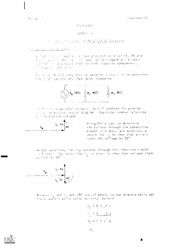
a'),11\ /td porallei IL, RC and
,Jeal 'Le (dis'egard all circuit
Ci r I I On 1,, rCJCt Ve Component s
n ,1 LH, LC parallel cirk_u t is to determine
anu ',hen 1Otdi impedahCe
r---
120y x 40Pc 30C1
0 p3 .011e1 L,rceit, we i 11 arlalyr_e the problem
'he cLrrLnt vector Ulag'-am Again our connon reference
4aEA 90',
Us,ng Ohm's Law, ue determineInc current through the capacitive
branch is 4 amps, and construct avector for Ir to show that currentleo,es the vosrlage by 90'
cap Je;erm,ne ihat t';c: current_ through the lye pranch
3 dr-Ir'' veclo- for 1L 1,-, dra\,,1 lc show that vol cage 1eadr,
1 :, 90'
EA
I, 3090
B,cab,e 1 and 1
L
are 180 out of phase, we can algebraically add
tHe,c uuaH,1tles to ',O1,/c for total currfrat
IC 0 +
1 0 13 a
+11a

1
's La e Lon Solve tLf
7
IT
1)0
110
Four I Leo -IV
ZT er td ler than either X ur X Th 15 i 5 an 1 mpo tan t
a pot arl el LC , Lu t and e 1 1 di scus5 i I further
c of pu ,er
,rc L out e- L anJ C
C
I
ied current I I con t !nue to
Dr,MPED NAVE
due to the di scharg 1 ng of the capac for and the
1 ap. ng f IC Id of the Inductor The cur rent 11 cent 'nue to
.Hatt back and for th bet 'een L and C at a d imtn 1 shiny rate
da ped ,ave Is formed due to the re s 1 stance present in any
hrac.t lcal circuit This ac t on s knoon as /heel act on or
11 let- 1 eh icct
r 1 d,o3 1 CI Lu it at Natural Resonant ;-reguency
11r_ ice t " X dnd X1
are equal, both 30 ohms
x 30,E
Current i, flu ing in both branches of the network 1 = + amps
a.-d IL amp,, The current vector diagram is plJLed below
EA
I
c 4°
IL 4°
C
1
Fuurtecn-IV
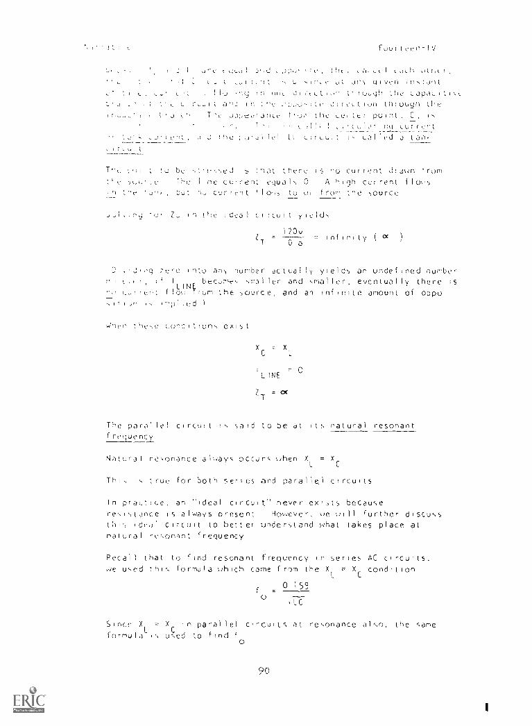
tlt . Ottlt rLimit ,ur ref it ,s Jt Jh!, (liven instant
in Of It dl ruuqh the LapJLIIIL:t rLuit aj in the drre,tion through the
,h The odi,earariLe the Leiter point, C, is
c 1 ! , rcula; LurrcntJ lel Li ,11,,,11 rs cal led 3 tam,
to be sirt-s,ed ;hat ther-c is no cur rent drawn fromtle The line current equals 0 A high current flogsin tbe tut n, current '10'0, to ur frum the source
w I tne ideal ci rcuit yields
120vZ =
0 a= infinity ( a )
q ;ere into and number actually yields an undefined numbere.ir, i1 I
LINEbecome, smaller and smaller, eventually there is
nu cJirct floo `rum the source, and an infinite amount of oppo-sii, In1p1 Iffd 1
tIlese conditions exist
XC X
LINE
ZT 0(
The parallel circuit is said to be at its natural resonantfreguenci
Natural resonance always occurs then XL = X
Thi, is true for both series and parallel circuits
In pra,t:ce, an "ideal circuit" never exits becausereritstance is always present However, tie gill further discuss
ideal circuit to better understand what takes place atnatural re,,on.lnt frequency
Recall that to find resonant frequency in series AC circuits,,qe used this formula ohich came from the X = XC condition
f =0 159
o,LC
Since X = X in paral lel circuits at resonance also, the same
formulaL
used to find f
0
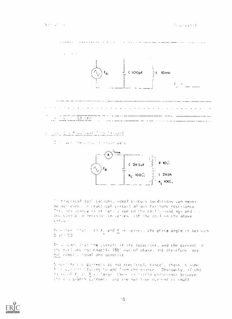
C 100pf 10mh
I '
'line
t Ica I ar,p1 Icat Ionc Ideal c rcu I t Condit [ o,)-, can never
pc a r jcj Ca 1 c rcu 1 t al hoc cone res c tance
T "1, rc I,ta'ce pr I due to the co: 1 'c /Ind ing c and I ,
c 'd a ri 1 c tor In aerie, Ith the co 1 1 in the abovec r_U
and P in .oriu-,
50the phac,e angle bet wen
T- :' a the Cur rent n the capac inr and t he current I r,
1 .;r;_. --rj; r.xac 180 nut Of nha\e Ind therefore arcm, Ci.)C ane 0;)f)05
S l OC. T G Cur -.r; c Co nr)t Cram 1 Ct C 1. C.--inoe 1 thele IS ',um('
r 1(2, . rq Ire Om.: Itr,m t suirce Ohv ou.,ly f t he
r ! R 1 1.a rr30 1 1 1 !N d 11 rnncr be t,%)nen;r ; TJ r ren ,flj the ne i 1 Inv corrr f I ,m)..11 1
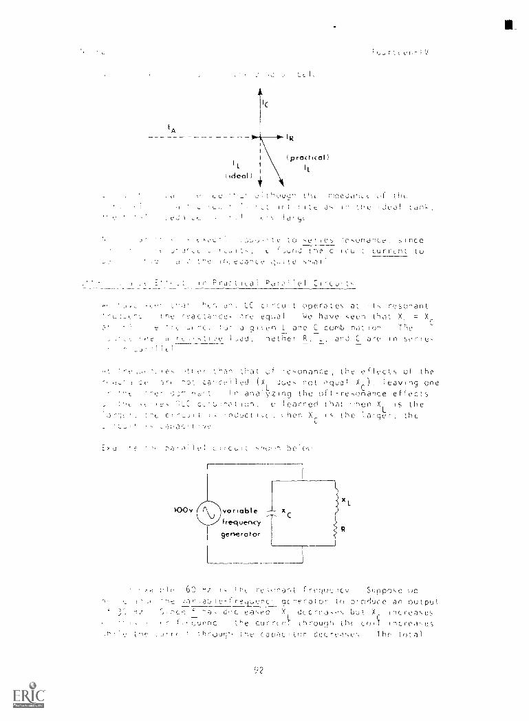
EA
IC
IR
IL.
ideal)
t pro( ficol )
7,
f,,urttek-IV
to t.I1L in eJe Ld tht,
3,, In ;fle ideal
tkOC'I te to sr Cs 1-esunance, nec
t J-Jrct t f,A,Jhd fl t' Clriuti curr,nt tuin.tdance
in Practi,a1 ,_!folle1 Circut-
kt.', an, LC circuit operates at it', resonanttfle reactance- are equal We have seen tht-lt X = X
, . e r, a q 0n L and C comb on Tked hetTrTer R L, and C are in series
t
e' tHan that of re,,onance, the efiects of the
ce ot car,celled (XL Juts not equal Xr), leaving one
he VcinH n analyzing the oft-resonance effects7LC c learned that ''hen X is the
t-, ci I I nCnc hen Xc is the larger, thc
Ilt2; belot,
100v
in 1, ,h, frequcv Suppose tie;ariat,ie-fre,iuenc acrieraior n produce an output
` ha, dc eased X utcrea,e,, but Xr nc re-as es
1 r f C.U1'nC the currcnC,I through th( c()1T increa=e,s
,h1le Ire caDacitnr decre.1,,e', The total
(92
nou teen -IV
, f I ' i.1 t aupI Icc
r_luLl.
appeo, inJoLti,:e
,015e Ine source frequency above 1 X Increases andL.
X, htis frequency, the current through the corlthe Lur,ent through the capacItor in,reases
tfli 'fufl the capac ',lye current and it leads
,:page (ICE) Therefore, th e circuit behaves I Ike
1,c c I rcu 1 t
C see
frequency above 1 the parallel
oopears capac,tive
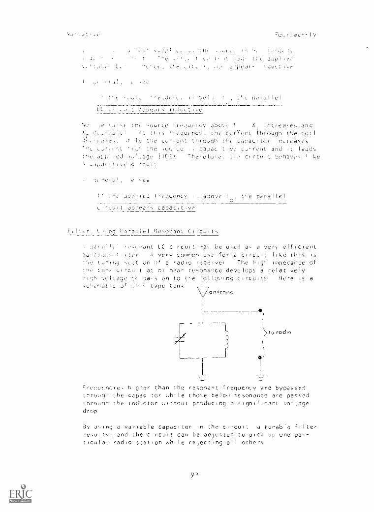
nn, Parallel Resonant Circuits
ParalIc 1 res'onant LC cIrcutt ma, be used as a very efficientt, ;ter A very common use for a circuit like this is
the toning s,,ction of a radio receiver The high impedance oftne tan, circuit at or near resonance develops a relativelyhigh voltage tr pa-s on to the folloIng circuits Here is a
,chemot,c or this type tank
_17
7
Freuut-.:ncle, higher than the resonant frequency are bypassedthrough the capacitor uhile those belou resonance are passedthrourlh the Inductor tiithout producing a significant voltagedrop
\> to radio
By using a variable capacitor in the CirCull a tunable filter
re',ult',, and the circuit can be adjusted to pick up one par-ticular radio station while rejecting all others

input \)
Ft.,:fteLM-iV
tffk- ' t ,olIW\ t fViii 3 ClfCUll
fi'' ':.J. Lfr 111(,; If ),,),ft,nt., , 11)1 yOuf TV),
3 :dflk ,Lui, itkc ,,,),1 cne, onJ Juju-,[ !:
output
._______________i_ s
ILI-, i, L3Iltd j bondclimIndt.lon fIW:f for it
,__6, uut a limled fange offrequencle,, uttliout great
attectIng 51gnal5 above orbelo,, 1-, cutoff freque.ILle5
:,T. THIS POINT, YOU MAY TAKE THE PROGRESS CHCK, OR YOU MAY STUDY24i( T.-1F OTHER RESOURCES LISTED IF YOU TAKE THE PROGRESS
GrIEC''. ANSWER Lt.. OF THE QUESTIONS CORRECTLY, GO TO THE NEXT
LESSON IF NOT, LTUDY ANY METHOD OF INSTRUCTION YOU WISH UNTIL1'01) CAN ANSWER ALL THE QUESTIONS CORRECTLY
'1
I
1
a
E;r777 ' 1E0 tori
V
33 StinJDC doti p ay1 y9v
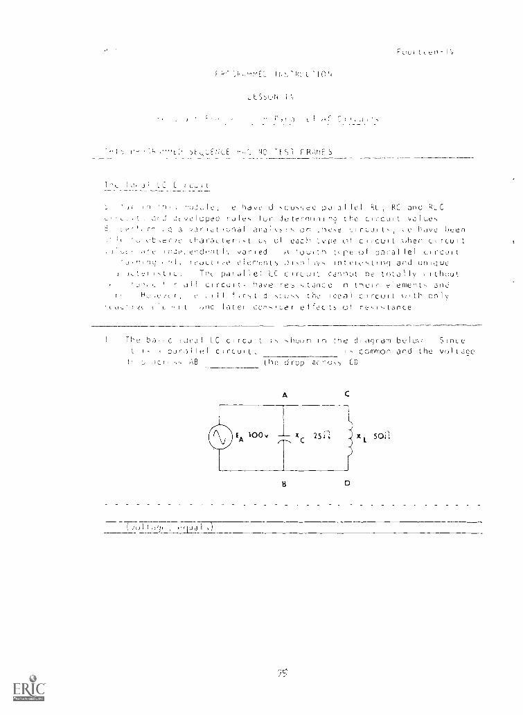
c.)6P 1 (IA ;)y1 pue uoiuwoD SI 'lln7JIC [:-I I I r,` _I PC l
a-.)Li s No( oci wCJbt'IP 2L0 u1 ur\oLi-. I 11nDJ ID 71 IC1 -ec;
;-)Du in sl Da); a I 2nI Dui-r_.) Ia1el puc, -II I -1i, 1
A 1 U0 LI1 '\ 1 I nD.., J Ieapl UL; p CSJI4 I I I ' 7 /fl POE' ',1LIC)Il/j11-) _1 l;-,y1 u l z-)Durl ,oRaJ iip , ;
noLi 1 ,s e Col ;lc; inuue,) CIn -LI Dl IP ,-)nH un pue, bui istl,) Cul (I I r Ll:I,JD 1nPC'j
In-D..1c) la( ('(1 1),1 I Jen ,
I nDJ uayn 1Irl)11 tC) 't.1,1\1 ;;) 1,, J CJE--sr,
u;);')(1 ;-)AcLi ' in ,s s \ [Pue tpuni c U.,
pn CInDi I J ;,N 1 bu I LiI IUJ al c)p n.; p )(1 0 z'/, 1^ ;' pue 121 ICI I eIrd n pot, ,
; I fi 1
r I -0,T)); r),-)
S3W;HJ LS31 ON
I III s' tc d
Al NRC:11
I l. D ""),41
L
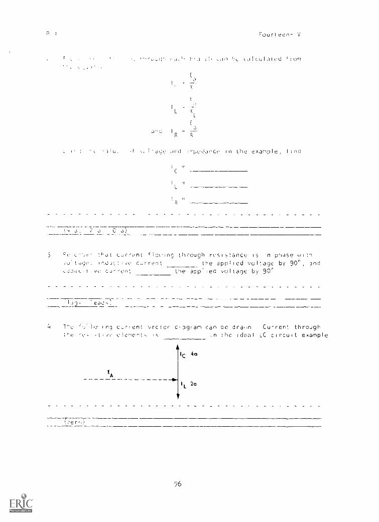
Jnd I
xL
a
Fourleen-IV
L, '3L LJILulated horn
aye dnd lore,iance fl he example , Ind
C
I ,
R
CI; a, 2 a, 0
3 Pc :hat current f10%;Ing through res15tance Is in phase withvo!tdye, InJuctivc current the applied voltage by 90°, and
vu cur ,en', the applred voltage by 90'
L13gh leach)
Tuc Hi b Ing current vector dtagram can bc drarn Current through,t vc cme nt I s ,n the ;deal LC cIrcult example
EA
Ic 4a
I
L2a
96
1 '
Four t. eel,- I V
RL L I n U C I JCId I 1 ht._ 11
JUiJ trr T ''CJ ng Ha
Lb, t Liecirt.-c5Ll' L iJJ ni q I 1 u'r1L
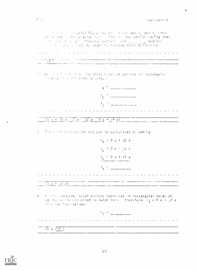
t1t"' ',/c.2 L) CUrIP n rLLLJrlquIa3,1; I cz.. it
I=
IC
+ ,3 0 j 2 a 0 a + a)
T, tl1 L.J1 t cur, ent can be calculated b\ add, ny
I = 0 a 4 JO aP,
iL 0 a 12 a
I -,- 0 a + j a
IT
2 a)
, exar t, I e total current Pxpre,,sed in rectangular r natal ionc,n,,L'r- led to polar form The no fore , IT 0 a + j2 a
in ; ) a r f urn) be
T
12 a /90 )
97
P.I. Fourteen-IV
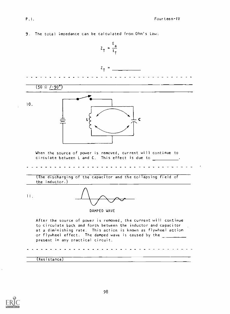
9. The total impedance can be calculated from Ohm's Law:
ZT
(50 Q /-90 )
.,---!:
10.
L C
When the source of power is removed, current will continue tocirculate between L and C. This effect is due to
(The discharging of the capacitor and the collapsing field ofthe inductor.)
DAMPED WAVE
After the source of power is removed, the current will continueto circulate back and forth between the inductor and capacitorat a diminishing rate. This action is known as flywheel actionor flywheel effect. The damped wave is caused by the
present in any practical circuit.
(Resistance)
98
d
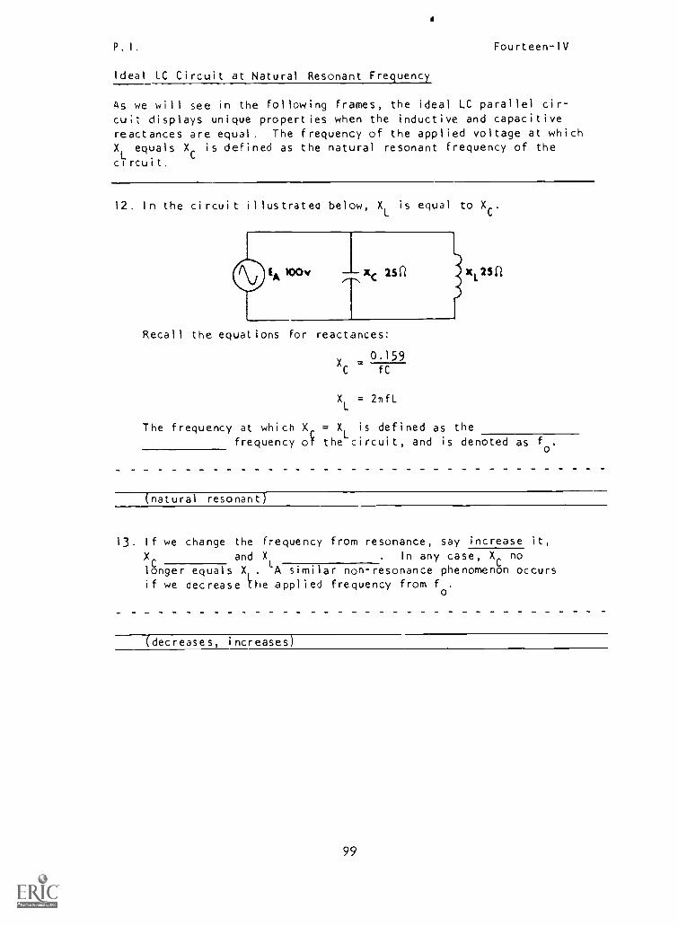
P. I, Fourteen-IV
Ideal LC Circuit at Natural Resonant Frequency
As we will see in the following frames, the ideal LC parallel cir-cuit displays unique properties when the inductive and capacitivereactances are equal. The frequency of the applied voltage at whichXL
equals XC
is defined as the natural resonant frequency of the
circuit.
12. In the circuit illustrate() below, XL is equal to X.
Recall the equations for reactances:
0.159X =C fC
XL
= 211fL
L252
The frequency at which X, = XL is defined as the
frequency of the circuit, and is denoted as fo.
(natural resonant)
13. If we change the frequency from resonance, say increase it,XC
and XL . In any case, XC
no
longer equals X .
LA similar non-resonance phenomenon occurs
if we decrease the applied frequency from fo.
(decreases, increases)
99
P.I. Fourteen-IV
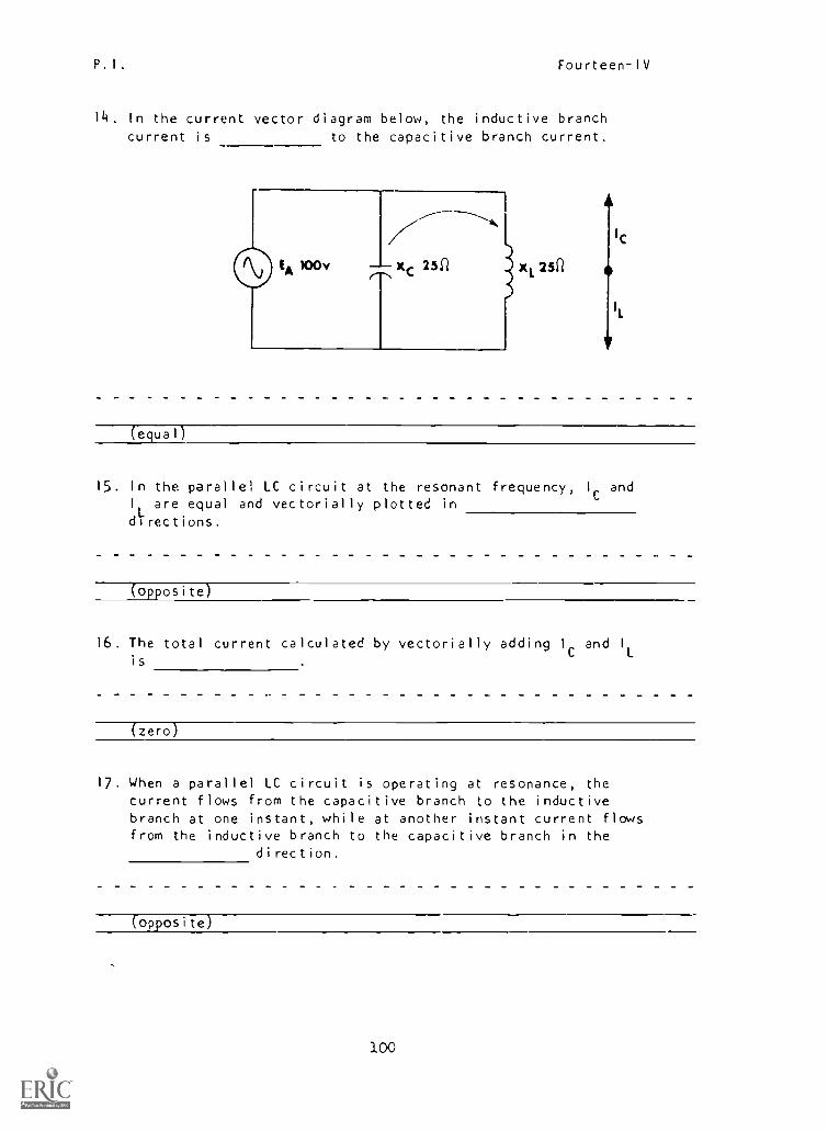
14. In the current vector diagram below, the inductive branchcurrent is to the capacitive branch current.
252
IC
IL
(equal)
15. In the parallel LC circuit at the resonant frequency, lc andI
Lare equal and vectorially plotted in
directions.
(opposite)
16. The total current calculated by vectorially adding lc and I
Lis
(zero)
17. When a parallel LC circuit is operating at resonance, thecurrent flows from the capacitive branch to the inductivebranch at one instant, while at another instant current flowsfrom the inductive branch to the capacitive branch in the
direction.
(opposite)
100
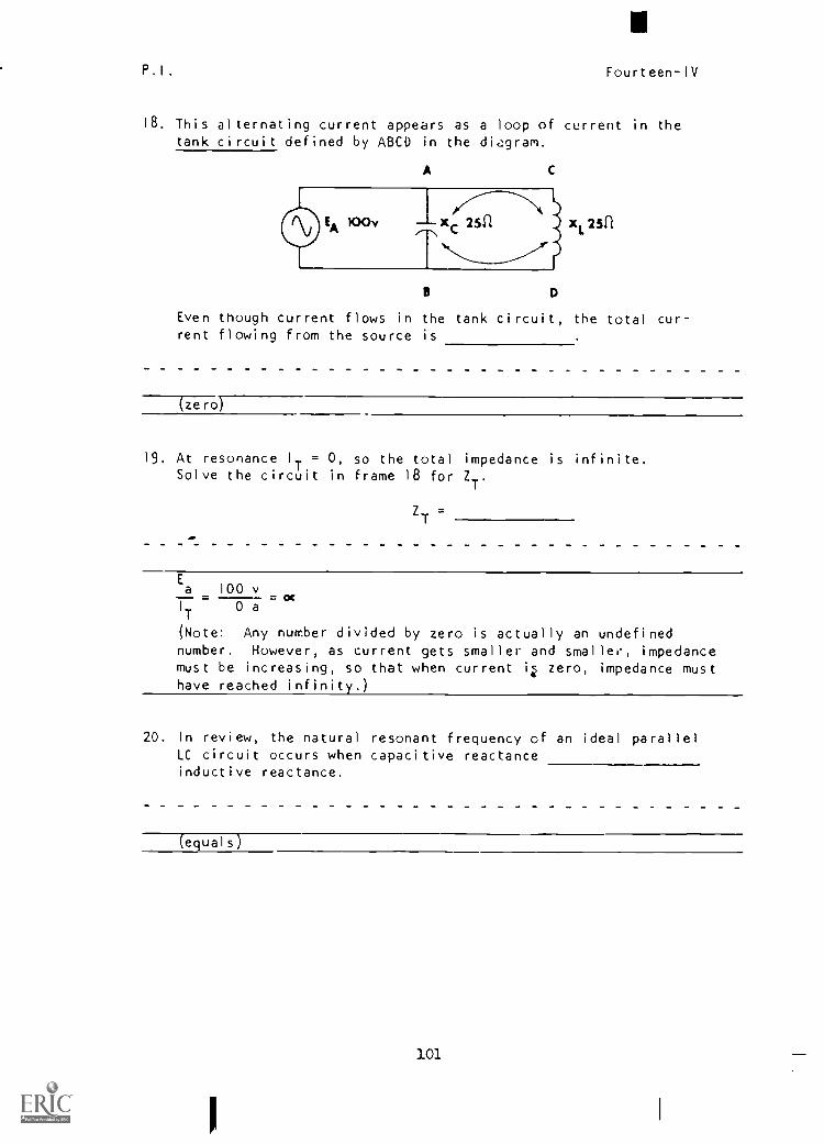
P.I. Fourteen-IV
18. This alternating current appears as a loop of current in thetank circuit defined by ABC° in the dic2gram.
A
x 25n
Even though current flows in the tank circuit, the total cur-rent flowing from the source is
(zero)
19, At resonance I = 0, so the total impedance is infinite.iSolve the circuit in frame 18 for Z
T.
ZT =
Ea 100 v
- ocIT 0 a
(Note: Any number divided by zero is actually an undefinednumber. However, as current gets smaller and smaller, impedancemust be increasing, so that when current zero, impedance musthave reached infinity.)
20. In review, the natural resonant frequency of an ideal parallelLC circuit occurs when capacitive reactanceinductive reactance.
-(equals)
101
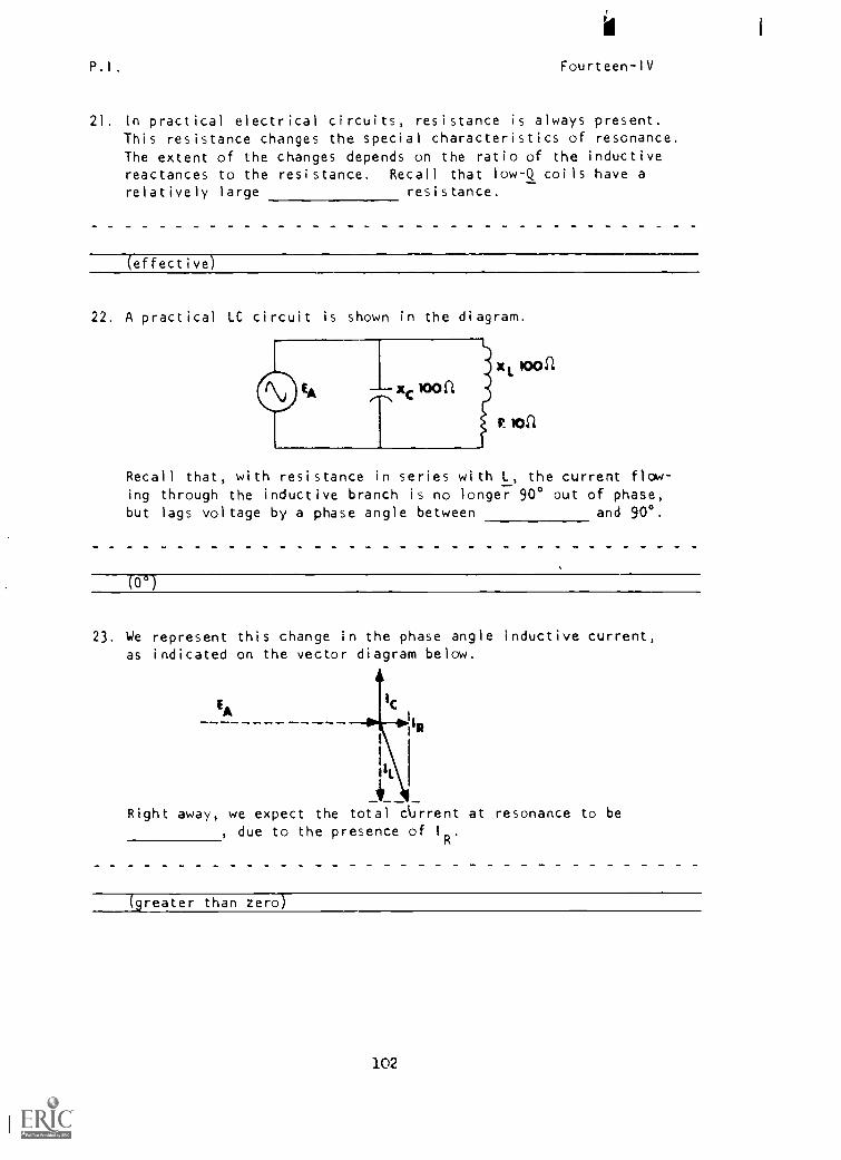
P,I. Fourteen-IV
21. In practical electrical circuits, resistance is always present.This resistance changes the special characteristics of resonance.The extent of the changes depends on the ratio of the inductivereactances to the resistance. Recall that low-Q coils have arelatively large resistance.
effective)
22. A practical LC circuit is shown in the diagram.
Recall that, with resistance in series with L, the current flow-ing through the inductive branch is no longer 90° out of phase,but lags voltage by a phase angle between and 90°.
(0°
23. We represent this change in the phase angle inductive current,as indicated on the vector diagram below.
EA
Right away, we expect the total current at resonance to be, due to the presence of I
R.
(greater than zero)
102
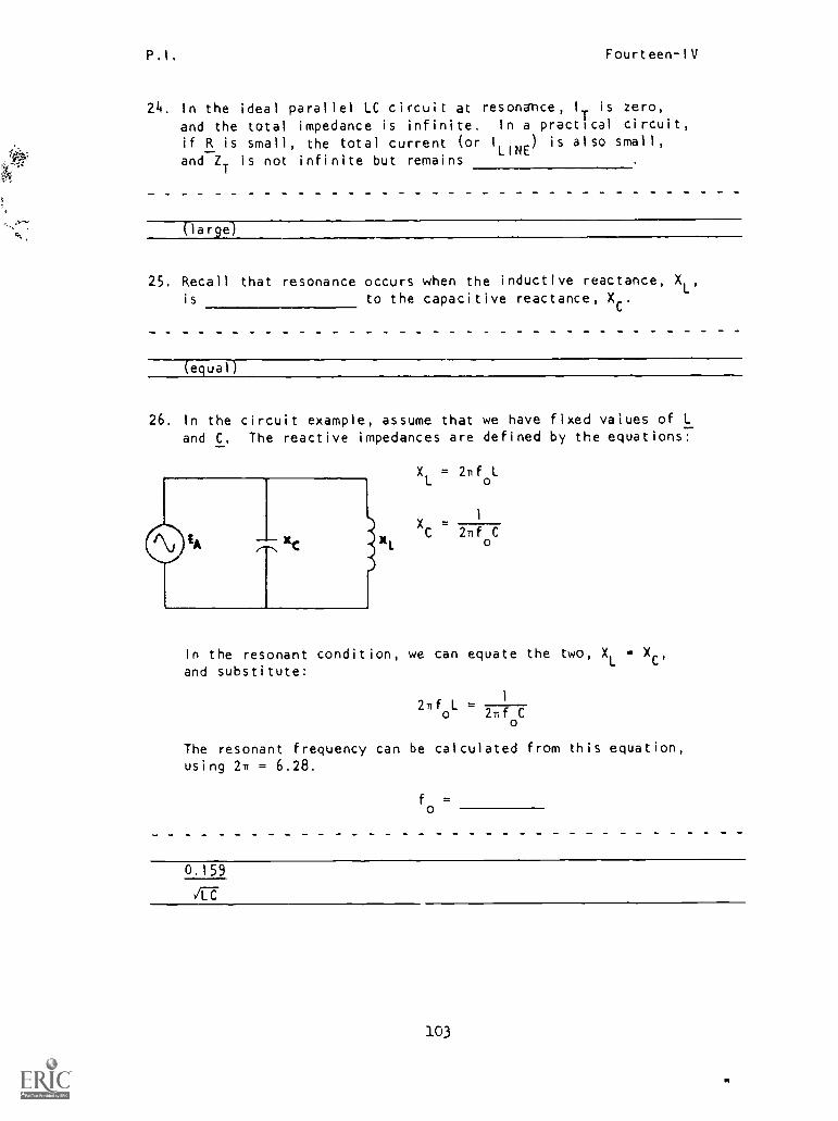
P.I. Fourteen-IV
24. In the ideal parallel LC circuit at resonance, I
Tis zero,
and the total impedance is infinite. In a practical circuit,
if R is small, the total current (or I
LINE) is also small,
and ZT is not infinite but remains
(large)
25. Recall that resonance occurs when the inductive reactance, XL,is to the capacitive reactance, X .
(equal)
26. In the circuit example, assume that we have fixed values of L
and C. The reactive impedances are defined by the equations:
XL
= 2nfoL
XC 2nf
oC
In the resonant condition, we can equate the two, XL = Xc,and substitute:
2nf L0 2flf C
The resonant frequency can be calculated from this equation,using 2n = 6.28.
fo
=
0.159
JET
103
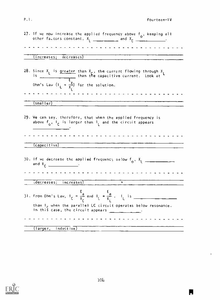
P.I. Fourteen-IV
27. If we now increase the applied frequency above fo
, keeping allother fa,tors constant, XL and X
C
(increases; decreases)
28. Since XL
is greater than Xr, the current flowing through XLis than the capacitive current. Look at
E
Ohm's Law for the solution.(IL X
al
L
(smaller)
29. We can say, therefore, that when the applied frequency isabove f
o'I
Cis larger than I
Land the circuit appears
(capacitive)
30. If we decrease the applied frequenc\, oelow fo'
XL
and XC
kdecreases; increases)
Ea
E
X31. From Ohm's Law, Ic = and I
L X
a= . 1
Lis
C L
than I
rwhen the parallel LC circuit operates below resonance.
In thig case, the circuit appears
(larger, inductive)
10li
pl

P.1, Fourteen-1V
32. Parallel resonant circuits are commonly used as filters toselect or reject narrow bands of frequencies. Based on what
you know about filters and parallel resonant circuits, whichof these is a bandpass filter?
IN IN
OUT
I( A)
33. Choice A is correct, for the parallel LC circuit has a highimpedance at or near resonance only. At any frequency lowerthan its lower f , the signal is shorted through the inductor
to ground withoui developing a usable output voltage.
A signal at a frequency of 20,000 Hz useful at
is/is notthe output of a bandpass filter with the resonance curve shown?
30 KHZ1
1Z
1
knomorfc uPPiir fco23 KHZ 32KHZ
(is not)
105
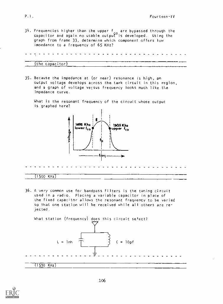
P.I. Fourteen-IV
34. Frequencies higher than the upper f are bypassed through thecapacitor and again no usable outpJ is developed. Using thegraph from frame 33, determine which component offers lowimpedance to a frequency of 65 KHz?
the capacitor
35. Because the impedance at (or near) resonance is high, anoutput voltage develops across the tank circuit in this region,and a graph of voltage versus frequency looks much like theimpedance curve.
What is the resonant frequency of the circuit whose outputis graphed here?
eq------4.
(1500 KHz)
36. A very common use for bandpass filters is the tuning circuitused in a radio. Placing a variable capacitor in place ofthe fixed capacitor allows the resonant frequency to be variedso that one station will be received while all others are re-jected.
What station (frequency) does this circuit select?
L = lmh C = lOpf
(1590 KHz)
106
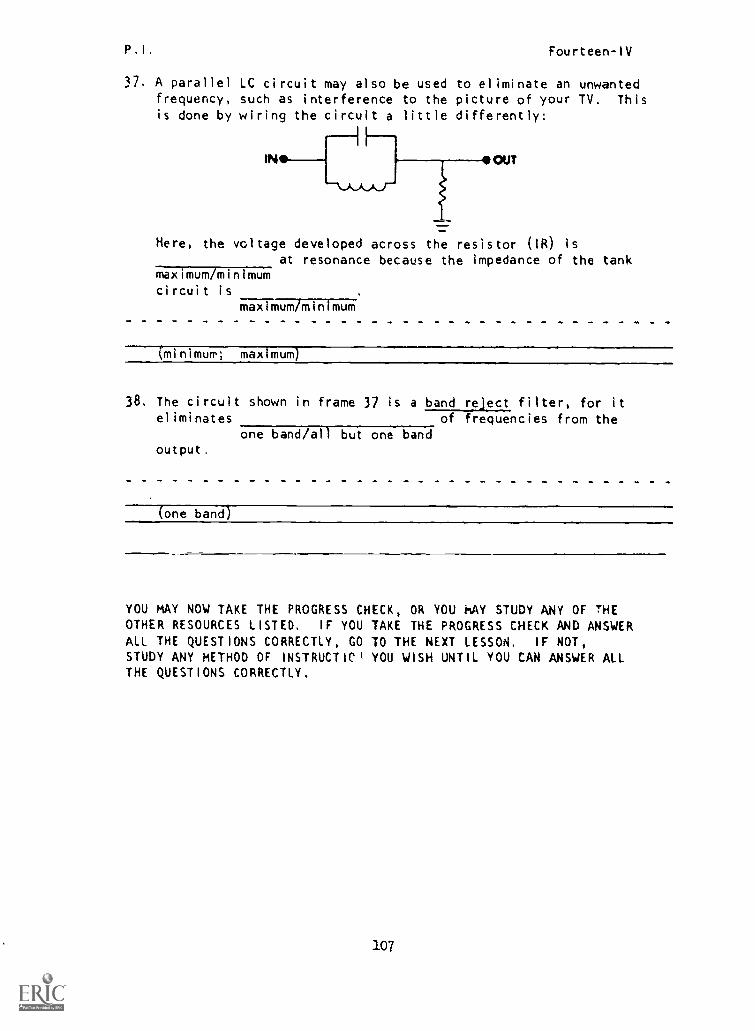
P,I, Fourteen-IV
37. A parallel LC circuit may also be used to eliminate an unwantedfrequency, such as interference to the picture of your TV. This
is done by wiring the circuit a little differently:
IN OUT
Here, the voltage developed across the resistor (IR) is
at resonance because the impedance of the tankmaximum/minimumcircuit is
maximum/minimum
(minimum; maximuMj
38. The circuit shown in frame 37 is a band reject filter, for iteliminates of frequencies from the
one band /all but one bandoutput.
(one band)
YOU MAY NOW TAKE THE PROGRESS CHECK, OR YOU MAY STUDY ANY OF THEOTHER RESOURCES LISTED, IF YOU TAKE THE PROGRESS CHECK AND ANSWERALL THE QUESTIONS CORRECTLY, GO TO THE NEXT LESSON. IF NOT,
STUDY ANY METHOD OF INSTRUCTICI YOU WISH UNTIL YOU CAN ANSWER ALLTHE QUESTIONS CORRECTLY.
107
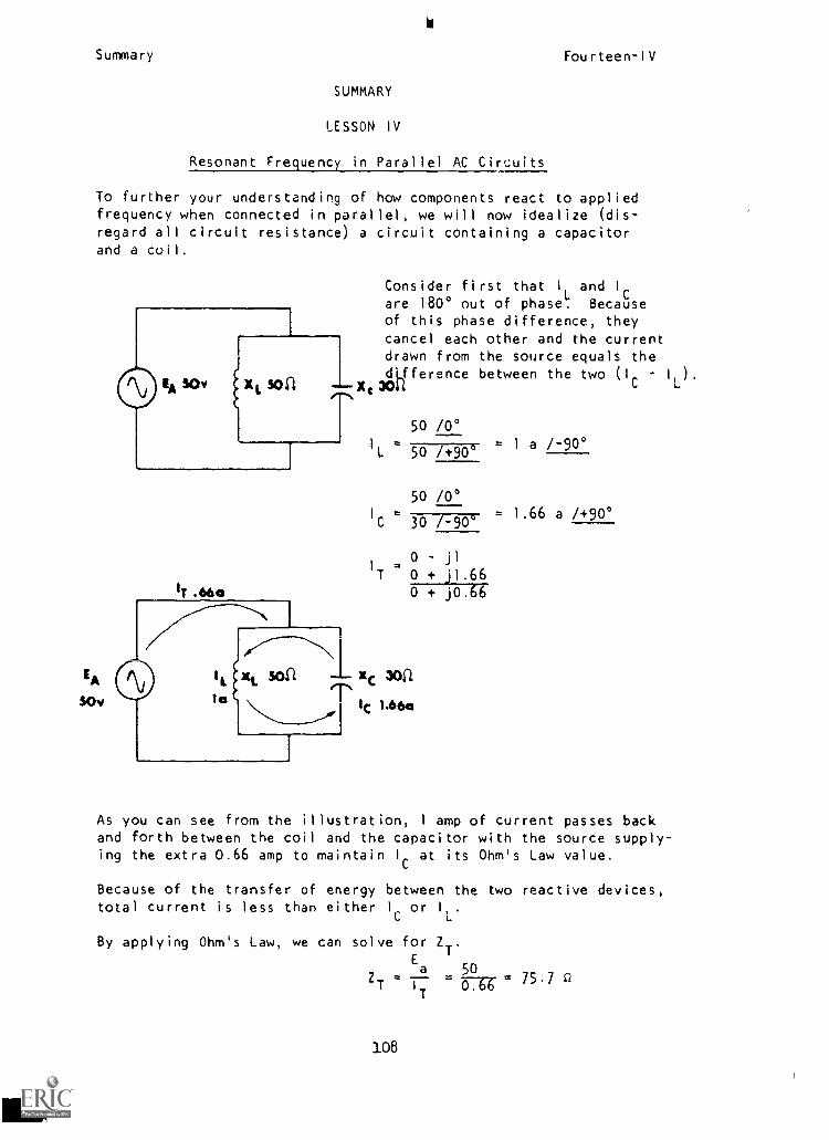
Summary Fourteen-IV
SUMMARY
LESSON IV
Resonant Frequency in Parallel AC Circuits
To further your understanding of how components react to appliedfrequency when connected in parallel, we will now idealize (dis-regard all circuit resistance) a circuit containing a capacitorand a coil.
T .66a
Consider first that I
Land I
are 180° out of phase. Becauseof this phase difference, theycancel each other and the currentdrawn from the source equals the
XdLfference between the two (IC - I
L).
0 044
50 /0°
1 =L 50 /+900
- 1 a /-900
50 /0°I
C=
30 /-901.66 a /+90°
0 - jl
ITT 0 4- j1.66
0 t j0.6i
IA San xc
sov la I lc 1.66a
As you can see from the illustration, 1 amp of current passes backand forth between the coil and the capacitor with the source supply-ing the extra 0.66 amp to maintain I at its Ohm's Law value.
Because of the transfer of energy between the two reactive devices,total current is less than either I. or I
L.
By applying Ohm's Law, we can solve for ZT.Ea 50
ZT I
T0.66 75'7 n
108
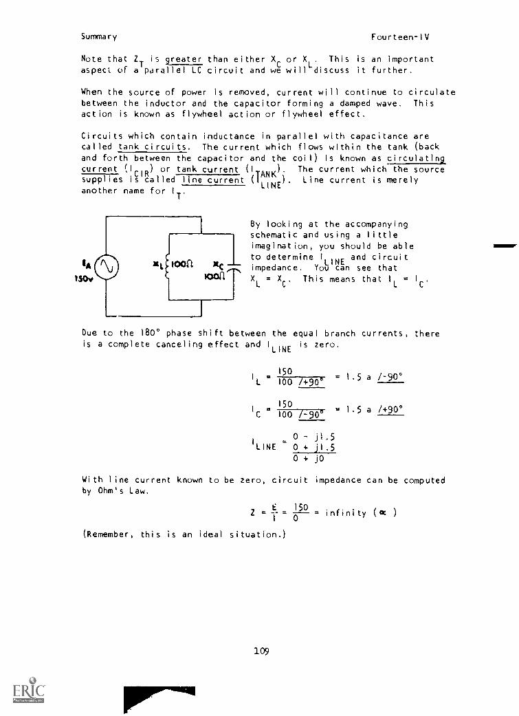
Summary Fourteen-IV
Note that ZT
is greater than either XCor X
L. This is an important
aspect of a
is
LC circuit and we will discuss it further.
When the source of power is removed, current will continue to circulatebetween the inductor and the capacitor forming a damped wave. Thisaction is known as flywheel action or flywheel effect.
Circuits which contain inductance in parallel with capacitance arecalled tank circuits. The current which flows within the tank (backand forth between the capacitor and the coil) is known as circulatingcurrent II
iCIR
) or tank current (ITANK
). The current which the source'
supplies is called line current (1LINE
) Line current is merelyanother name for I
T.
1A
1SOv
By looking at the accompanyingschematic and using a littleimagination, you should be ableto determine I
LINEand circuit
impedance. You can see thatXL
= XC
, This means that I
1.
= IC.
Due to the 180° phase shift between the equal branch currents, thereis a complete canceling effect and !LINE is zero.
I
L
I
C
(LINE
1501.5 a
1.5 a
1-90°100
150
/ +90°
1+90°100 /-90°
0 - j1,5
0 + '1.50 + j0
With line current known to be zero, circuit impedance can be computedby Ohm's Law.
Z =150
i=0
infinity (cc )
(Remember, this is an ideal situation.)
109
r
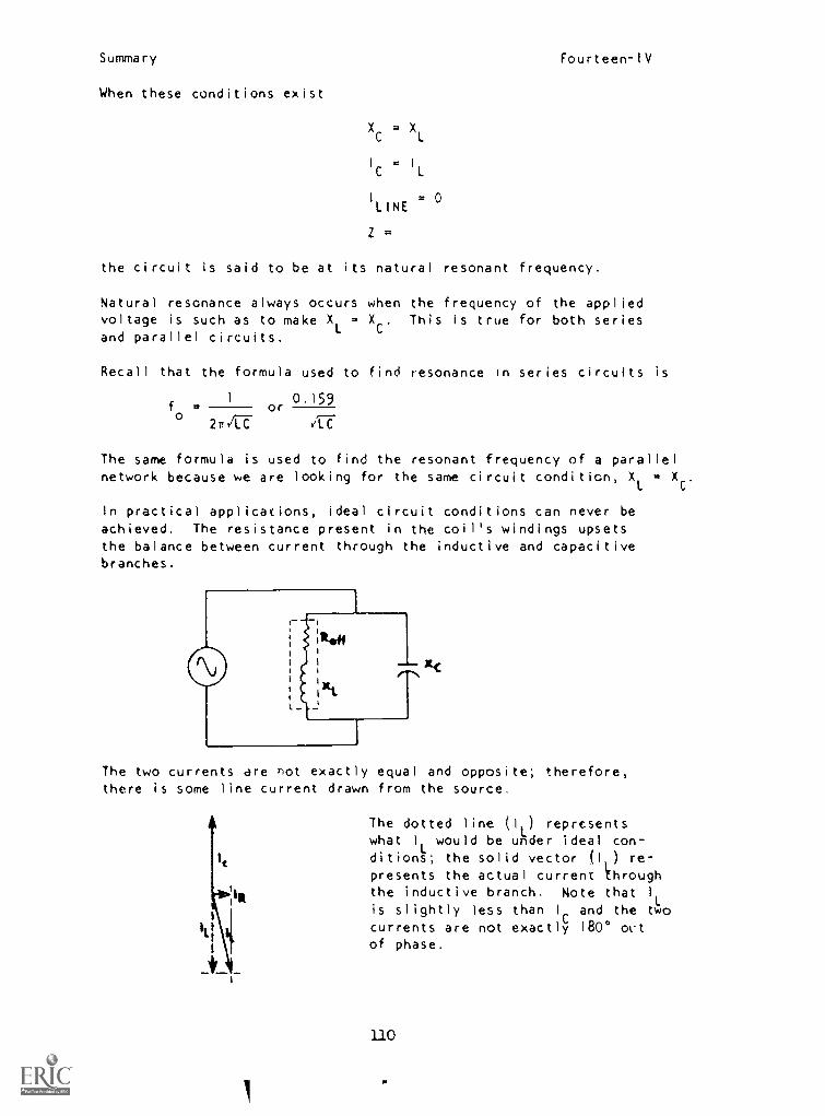
Summary Fourteen-IV
When these conditions exist
XC = XL
IC = IL
I
LINE= 0
Z=
the circuit is said to be at its natural resonant frequency,
Natural resonance always occurs when the frequency of the appliedvoltage is such as to make X
L= X This is true for both series
and parallel circuits.
Recall that the formula used to find resonance in series circuits is
1 0.159f = or
27/CT vLC
The same formula is used to find the resonant frequency of a parallelnetwork because we are looking for the same circuit condition, X
L= X .
In practical applications, ideal circuit conditions can never beachieved. The resistance present in the coil's windings upsetsthe balance between current through the inductive and capacitivebranches.
The two currents are not exactly equal and opposite; therefore,there is some line current drawn from the source,
A The dotted line (1 ) representswhat 1
Lwould be under ideal con
1t dittons; the solid vector (11) re-presents the actual current through
c)Ilk the inductive branch, Note that I
Lis slightly less than 1 and the two
ncurrents are not exactly
Clo0 0 out
of phase.
110
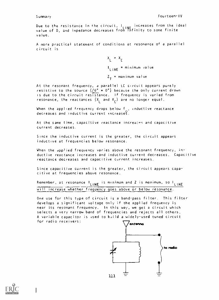
Summary Fourteen-IV
Due to the resistance in the circuit, I
LINEincreases from the ideal.
value of 0, and impedance decreases from infinity to some finite
value.
A more practical statement of conditions at resonance of a parallel
circuit is
XL = XC
= minimum valueI
LINE
ZT
= maximum value
At the resonant frequency, a parallel LC circuit appears purelyresistive to the source (/00 = 0°) because the only current drawnis due to the circuit resistance. If frequency is varied from
resonance, the reactances (XL
and XC) are no longer equal.
When the applied frequency drops below fa, inductive reactancedecreases and inductive current increases.
At the same time, capacitive reactance increa:oc and capacitivecurrent decreases.
Since the inductive current is the greater, the circuit appears
inductive at frequencies below resonance.
When the applied frequency varies above the resonant frequency, in-
ductive reactance increases and inductive current decreases. Capacitivereactance decreases and capacitive current increases.
Since capacitive current is the greater, the circuit appears capa-citive at frequencies above resonance.
Remember, at resonance I
LINEis minimum and Z is maximum, so I
LINE
will increase whether frequency goes above or below resonance.
One use for this type of circuit is a band-pass filter. This filter
develops a significant voltage only if the applied frequency isnear its resonant frequency. In this way, we get a circuit whichselects a very narrow band of frequencies and rejects all others.A variable capacitor is used to build a widely-used tuned circuitfor radio receivers:
antenna
111

Summary Fourteen-IV
The capacitance is varied to select the desired station while allother frequencies fail to develop usable outputs.
Wired like this the parallel LC network forms a band-reject filter
input Toutput
_______.AT THIS POINT, YOU MAY TAKE THE LESSON PROGRESS CHECK, OR YOU MAYSTUDY THE LESSON NARRATIVE OR 'THE PROGRAMMED INSTRUCTION OR BOTH.IF YOU TAKE THE PROGRESS CHECK AND ANSWER ALL OF THE QUESTIONS COR-RECTLY, GO TO THE NEXT LESSON. IF NOT, SELECT ANOTHER METHOD OFINSTRUCTION UNTIL YOU CAN ANSWER ALL THE QUESTIONS CORRECTLY.
112

NAVPERS 94558-I4a
BASIC ELECTRICITY AND ELECTRONICS
INDIVIDUALIZED LEARNINC SYSTEM
MODULE FOURTEEN
LESSONV
Effective Resistance in RL Parallel Circuits
Study Booklet
Bureau of Naval Personnel
January 1972
113
J
Overview Fourteen-V
OVERVIEW
LESSON V
Effective Resistance in RL Parallel Circuits
In this lesson you will study and learn about the following.
-practical RL circuits
-solving for current
-effect of Q of a coil in parallel
RL circuits
BEFORE YOU START THIS LESSON, PREVIEW THE LIST OF STUDY RESOURCES
ON THE NEXT PAGE.
Study Resources Fourteen-V
LIST OF STUDY RESOURCES
LESSON V
Effective Resistance in RL Parallel Circuits
To learn the material in this lesson, you have the option of choosing,
according to your experience and preferences, any or all of the
following:
STUDY BOOKLET:
Lesson Narrativc
Programmed Instruction
Lesson Summary
ENRICHMENT MATERIAL.
NAVPERS 93400A-lb. "Basic Electricity, Alternating Current."
Fundamental of Electronics. Bureau of Naval Personnel.
Washington, D.C. U.S. Government Printing Office, 1965.
YOU MAY NOW STUDY ANY OR ALL OF THE RESOURCES LISTED ABOVE. YOU MAY
TAKE THE PROGRESS CHECK AT ANY TIME.
115
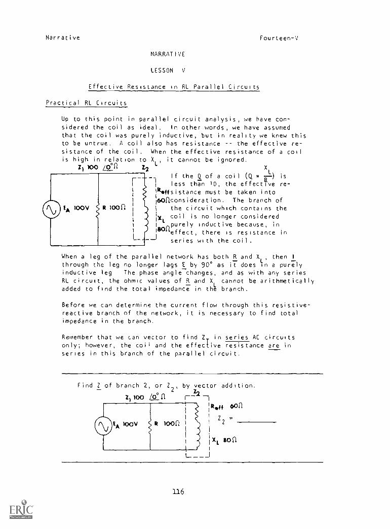
Narrative Fourteen-V
NARRATIVE
LESSON V
Effective Resistance in RL Parallel Circuits
Practical RL Circuits
Up to this point in parallel circuit analysis, we have con-sidered the coil as ideal. In other words, we have assumedthat the coil was purely inductive, but in reality we knew thisto be untrue. A coil also has resistance the effective re-sistance of the coil, When the effective resistance of a coilis high in relation to XL, it cannot be ignored.
Zi 100 /0°2 12 XL
If the Q of a coil (Q = ) is
less than 10, the effective re-1/1*ffsistance must be taken into
160aconsideration. The branch ofthe circuit which contains the
Ixt coil is no longer consideredpurely inductive because, in
aeffect, there is resistance inseries with the coil.
When a leg of the parallel network has both R and XL'
then I
through the leg no longer lags E by 90° as it does in a purelyinductive leg The phase angle changes, and as with any seriesRL circuit, the ohmic values of R and X
Lcannot be arithmetically
added to find the total impedance in the branch.
Before we can determine the current flow through this resistive-reactive branch of the network, it is necessary to find totalimpedance in the branch.
Remember that we can vector to find ZT in series AC circuitsonly; however, the coil and the effective resistance are inseries in this branch of the parallel circuit.
Find Z of branch 2, or Z2 ,
by vector addition.
Z1loo Lon F--
il
1I
100V R 1001l
IR " oonZ2
X SOn
_ _ _J
116
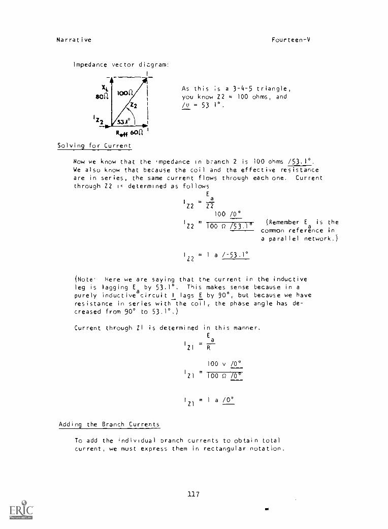
Narrative Fourteen-V
Impedance vector diagram:
I
AXL
soa
12 2 53.1°ii Ow,
R,44 bon
Solving for Current
Now we know that the .mpedance in branch 2 is 100 ohms /53.1°.
We also know that because the coil and the effective resistanceare in series, the same current flows through each one. Current
through Z2 lc determined as followsEa
I
Z2 Z2
loon As this is a 3-4-5 triangle,you know Z2 = 100 ohms, and
/0 = 53 1°.
100 /0°I
Z2 100 0 /53.1(Remember Ea is the
common reference in,a parallel network.)
I
Z2= I a /-53.10
(Note Here we are saying that the current in the inductiveleg is lagging Ea by 53.1°. This makes sense because in apurely inductive circuit I lags E by 90°, but because we haveresistance in series with the coil, the phase angle has de-creased from 90° to 53.1°.)
Current through 21 is determined in this manner.Ea
1 .Z1 R
100 v /0°
100 0 /0°
I
21= 1 a /0°
Adding the Branch Currents
To add the individual branch currents to obtain totalcurrent, we must express them in rectangular notation.
117
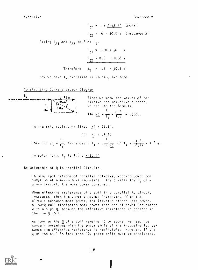
Narrative Fourteen-V
I
Z2= 1 a 1-53.1° (polar)
IZ2.6 jO.8 a (rectangular)
Adding Izi and 1Z2 to find IT.
I
Zl= 1.00 + JO a
I
Z2= 0.6 jO.8 a
Therefore I
T= 1.6 jO.8 a
Now we have I
Texpressed in rectangular form.
Constructing Current Vector Diagram
IA Since we know the values of re-sistive and inductive current,we can use the formula
0.8TAN /0 =
L TT-- = = .5000.IR
In the trig tables, we find: /0 = 26.6°.
cos /e . .8942
I 1
1.6Then COS /0 =I--R ; transposed,
IT COS
R
/0 or I T .8942= 1.8 a.
T
In polar form, . IT is 1.8 a /-26.6°
Relationship of Q in Parallel Circuits
In many applications of parallel networks, keeping power con-sumption at a minimum is important. The greater the Pt of agiven circuit, the more power consumed.
When ecfective resistance of a coil in a parallel Rl circuitincreases, then the power consumed increases. When thecircuit consumes more power, the inductor stores less power.A low-Q coil dissipates more power than one of equal inductance
with a high-Q, because the effective resistance is greater inthe low-Q coil.
As long as the Q of a coil remains 10 or above, we need notconcern ourselves with the phase shift of the inductive leg be-cause the effective resistance is negligible. However, if the
Q of the coil is less than 10, phase shift must be considered.
118
Narrative Fourteen-V
For your purposes in this school, you will disregard the ef-fective resistance of the coil unless otherwise directed.
AT THIS POINT, YOU MAY TAKE THE PROGRESS CHECK, OR YOU MAYSTUDY ANY OF THE OTHER RESOURCES LISTED. IF YOU TAKE THEPROGRESS CHECK AND ANSWER ALL OF THE QUESTIONS CORRECTLY, GOTO THE NEXT LESSON. IF NOT, STUDY ANY METHOD OF INSTRUCTIONYOU WISH UNTIL YOU CAN ANSWER ALL THE QUESTIONS CORRECTLY.
119
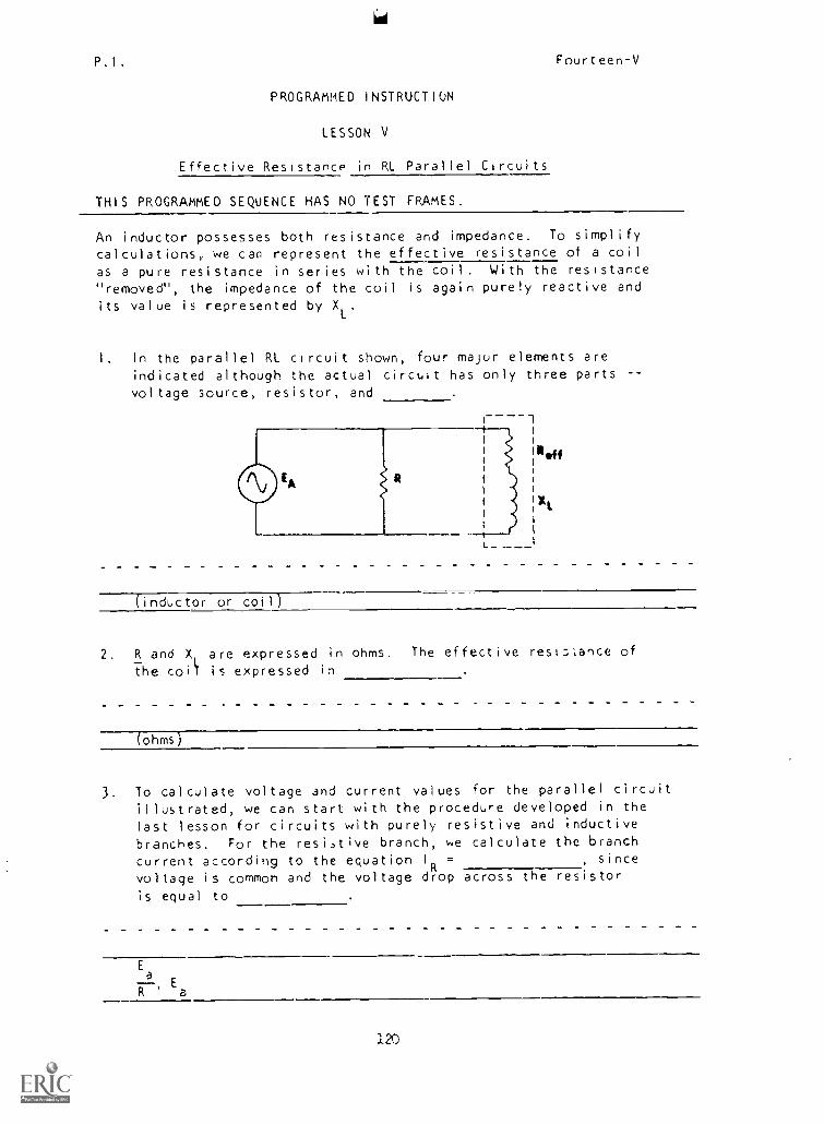
P,I. Fourteen-V
PROGRAMMED INSTRUCTION
LESSON V
Effective Resistance in RI. Parallel Circuits
THIS PROGRAMMED SEQUENCE HAS NO TEST FRAMES.
An inductor possesses both resistance and impedance. To simplify
calculations, we can represent the effective resistance of a coil
as a pure resistance in series with the coil. With the resistance"removed", the impedance of the coil is again purely reactive and
its value is represented by XL
.
I. In the parallel RL circuit shown, four major elements areindicated although the actual circuit has only three parts --
voltage source, resistor, and
(inductor or coil)
2. R and X, are expressed in ohms. The effective resiLtance of
the coil is expressed in
(ohms)
3. To calculate voltage and current values for the parallel circuitillustrated, we can start with the procedure developed in thelast lesson for circuits with purely resistive and inductive
branches. For the resi.,tive branch, we calculate the branchcurrent according to the equation IR = , since
voltage is common and the voltage drop across the resistoris equal to
Ea r
R' 'a
120
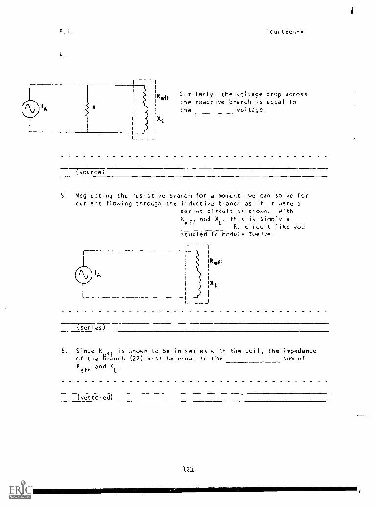
P.I. Hpurteen-V
R.0 Similarly, the voltage drop acrossthe reactive branch is equal to
the voltage.
XL
4
(source)
5, Neglecting the resistive branch for a moment, we can solve forcurrent flowing through the inductive branch as if it were a
series circuit as shown. With
Reff
and XL'
this is simply aRL circuit like you
studied in Module Twelve.
series
6, Since Rbranch
is shown to be in series with the coil, the impedanceof the branch (22) must be equal to the sum of
Reff
and XL
(vectored)
121
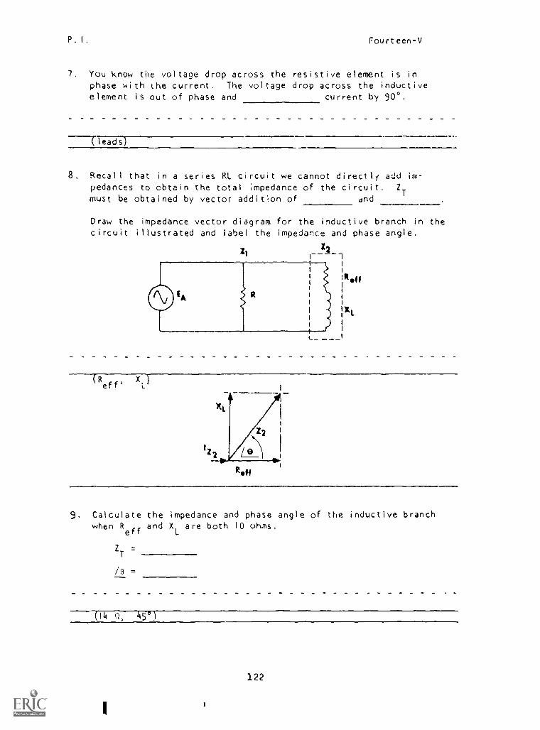
P. I, Fourteen-V
7. You know the voltage drop across the resistive element is in
phase with the current. The voltage drop across the inductiveelement is out of phase and current by 900.
- leads)
8. Recall that in a series RL circuit we cannot directly acid im-
pedances to obtain the total ;mpedance of the circuit. ZT
must be obtained by vector addition of and
Draw the impedance vector diagram for the inductive branch in thecircuit illustrated and label the impedance and phase angle.
(Reff' X174
...
9. Calculate the impedance and phase angle of the inductive branchwhen R
effand X
Lare both 10 ohms.
ZT
/0
(R Q, 450)
122
I
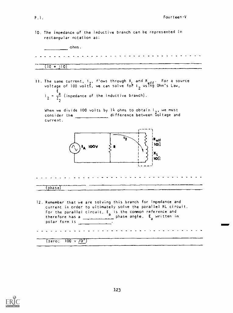
P.1. Fourteen-V
10. The imoedance of the inductive branch can be represented in
rectangular notation as:
ohms.
(10 + jio)
II. The same current, 1
2'f'ows through X and R
eff'For a source
voltage of 100 volts, we can solve fo? 1
2using Ohm's Law,
E1 = --
a(impedance of the inductive branch).
2 Z2
When we divide 100 volts by 14 ohms to obtain 12, we must
consider the difference between voltage and
current.
(phase]
12. Remember that we are solving this branch for impedance andcurrent in order to ultimately solve the parallel RL circuit.
For the parallel circuit, Ea is the common reference and
therefore has a phase angle. Ea written in
polar form is
(zero; 100 v /0°)
123
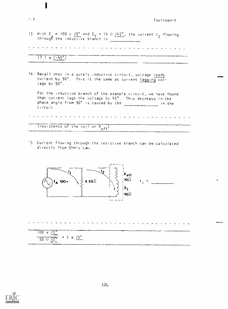
I
r.I Fourteen-V
13 With E = 100 v /0° and ZT = 14 Q /45°, the current 12 flowingthrougg the inductive branch is
(7 1 a 1-45°
14, Recall that in a purely inductive circuit, voltage leadscurrent by 90°. This is the same as current lagging vol-tage by 90°.
For the inductive branch of the example circuit, we have foundthat current lags the voltage by 45°. This decrease in thephase angle from 90° is caused by the in thecircuit
(resistance of the coil or Reff
)
15 Current flowing through the resistive branch can be calculateddirectly from Ohm's Law.
R 501i
1
loo v /0°
50 Q /062 a /0°
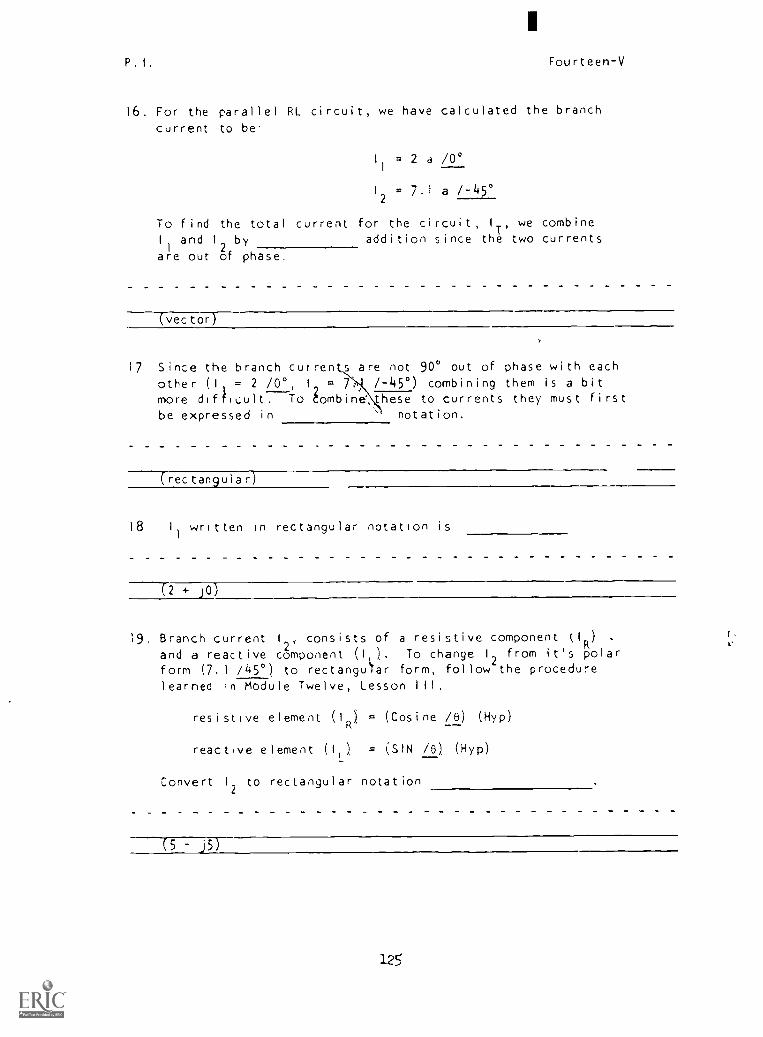
P. I. Fourteen-V
16, For the parallel RL circuit, we have calculated the branch
current to be
11 = 2 a /0°
12 = 7.1 a /-45°
To find the total current for the circuit' '
1 we combine
I
i
and 1
2by addition since the
Ttwo currents
are out of phase.
-(-vector)
17 Since the branch cutren s are not 90° out of phase with each
other (I, = 2 /0°, I = 7. /-45°) combining them is a bit
more difficult7To tombine these to currents they must firstbe expressed in notation.
(rectangular)
18 1
1
written in rectangular notation is
(2 + )O)
19, Branch current 1
2, consists of a resistive component (l
R) .
r,
and a reactive component (I,). To change I, from its polarform (7. 1 /45°) to rectangular form, follow the procedurelearned in Module Twelve, Lesson III.
resistive element (10 = (Cosine /8) (Hyp)
reactive element (11) = SIN /8) (Hyp)
Convert 12 to rectangular notation
-(5
125
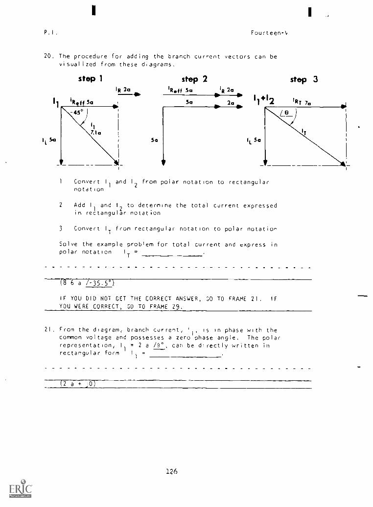
P . I Fourteen-
20. The procedure for adding the branch cur '-ent vectors can bevisualized from these diagrams.
step 1 step 2 step 3IR 2a IReff Sa IR 2a
41W 110-0 1 al50 2a 11'12 iot
)
543 Sa
Convert I
1
and 12 from polar notation to rectangularnotation
2 Add I
I
and I
2to determine the total current expressed
in rectangular notation
3 Convert I
Tfrom rectangular notation to polar notation
Solve the example problem for total current and express inpolar notation I
T=
(8 6 a /-35.5 )
IF YOU DID NOT GET THE CORRECT ANSWER, GO TO FRAME 21. IF
YOU WERE CORRECT, GO TO FRAME 29.
21. From the diagram, branch current, '1, is in phase with thecommon voltage and possesses a zero phase angle. The polarrepresentation, II = 2 a /9°, can be directly written inrectangular form Il =
(2 a + JO,
126

P.I. Fourteen-V
22 Converting 1 to rectangular notation is slightly more com-plicated and
2can Pest be visualized by looking at the drawing
showing one component in the standard direction and one com-ponent in the direction.
( standard )
1
2= 7 1 a /-45°
23. We can calculate the component values of the inductive branchcurrent (I
Rj11) by applying the trigonometric functions to the
vector diagram shown in Frame 20.
The resultant is represented by the current 12 (7.1 a /-45°).
To find the resistive value (1R'
)
'
apply the cosine function1
RCosine =
1
2
by rearranging the equation we get
I
R= Cosine 12
Cosine /-45° = 0.707
I
2= 7.1 a
Therefore, the resistive element of I
2=
(COS /-45° x 7.1 a or 5 a, Note: We are not attempting tosay that you vector current in a series circuit. We aresimply converting a vector representing that current frompolar notation to rectangular notation.)
127
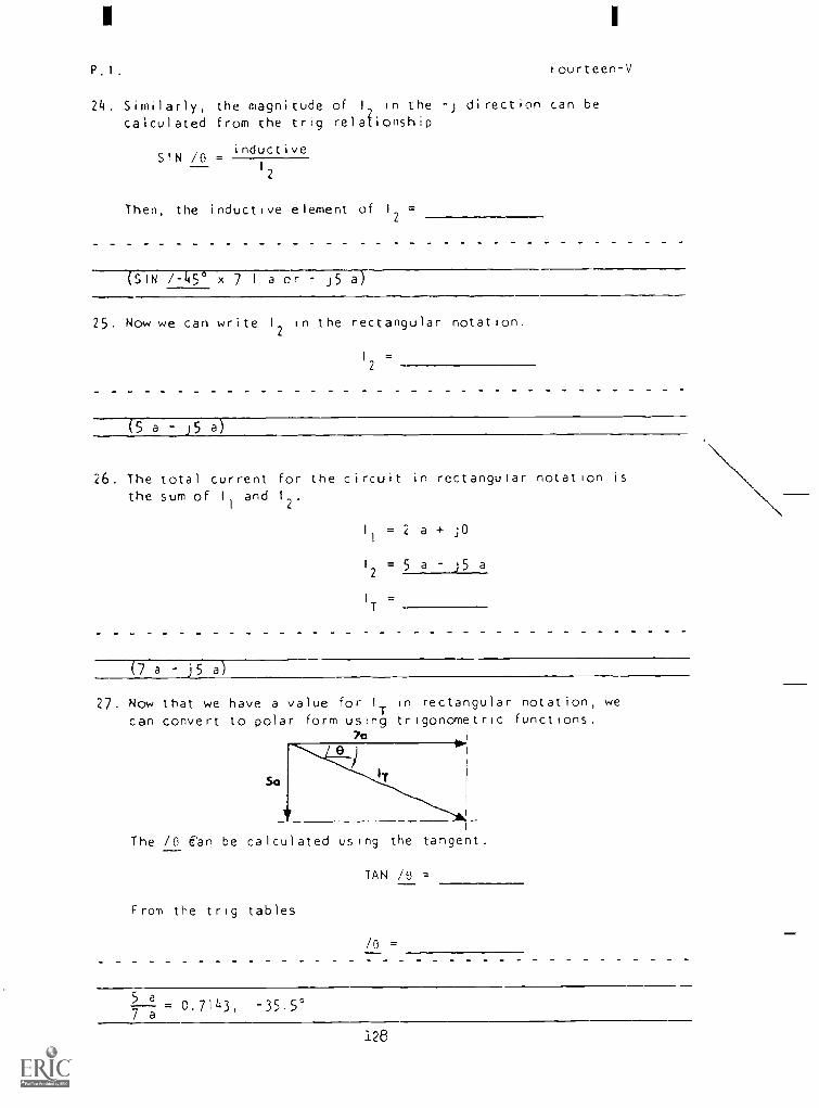
P.I. Fourteen-V
24. Similarly, the magnitude of I, in the -j direction can be
calculated from the trig relationship
S'N /0inductive
12
Then, the inductive element of 12 =
(SIN /-1450 x 7 1 a or J5 a)
25. Now we can write 12 in the rectangular notation.
12 =
(5 a j5 a
26. The total current for the circuit in rectangular notation isthe sum of I
1
and 1
2.
I
1
=2 a + ;0
12 = 5 a j5 a
I
T
(7 a j5 a)
27. Now that we have a value for I
Tin rectangular notation, we
can convert to polar form using trigonometric functions.70
The /0 Ean be calculated us,r,g, the tangent.
From the trig tables
TAN /0 =
/0 =
5 a7---; = 0.7143, -35.5°
128

P.I.
I
Fourteen-V
28. The magnitude of cancan be found using the equation for the
cosine of the phase angle'
iT
01 6 a /-35 5°)
29. Recall that any coil contains some resistance. A hi9h7Q
coil contains resistance or Reff
than a low-Q
coil.
A rule of thumb to follow is that if the Q of a coil is
greater than 10, the effective resistance ;s negligibleand can be considered
(lower, zero)
30. To prove the statement made in Frame 29. We will work aproblem first with a low Q coil, then in the following framereplace It with a high-Q cc'l and rework the circuit.
R so C1
Solve for Q
Z of branch 22
tReff
!3of1 3'2 (polar)
L
4 12 (rectangular)
14015. I,
IT
7 ZT
40(1 = = = 1.33
RLeff 3°
2 Z2 = 30 + J40 = 50 0 /+33.10
Ea
100 /0' v
3 2 a /-53.1°2 Z2 50 /+53.1°
129

I
P.I. Fourteen-V
4. I = (COS 1-53.10)(12
) 1 = (SIN /-53.1°)(2)R
(0.6004)(2)
L
(0.7997)(2)
1 2 j1 6
Ea 100 /0° = 2 /0°
5. 1
I Zi 50 /0'
6. 1
1
= 2 + j0
12 = 1.2 j1.6
I
T= 3.2 .0.6 (REC)
3.58 1-26.6° a (polar)
E 100 /0° v7. 2
T I
T
= 28 0 /+26.6°3.58 /-26.6°
31. Replace the low-Q coil with a high-Q.
Solve for.
1. Q
1- 1 2. Z2 .
1
1
IRef 3. 12 (polar) =
4
4. I
2(Rec) .
Xl
443f1 5. II
6. 1
T
7. ZT
x40
(1. Q . . = 10R
L
eff
2. Z2 = 4 + j40 = 40.28 0 /+84.3°
E 100 /0° va
3.i2
,
4, , 2.48 a /-84.3°
2 Z2 0.20 /+84.3°
130
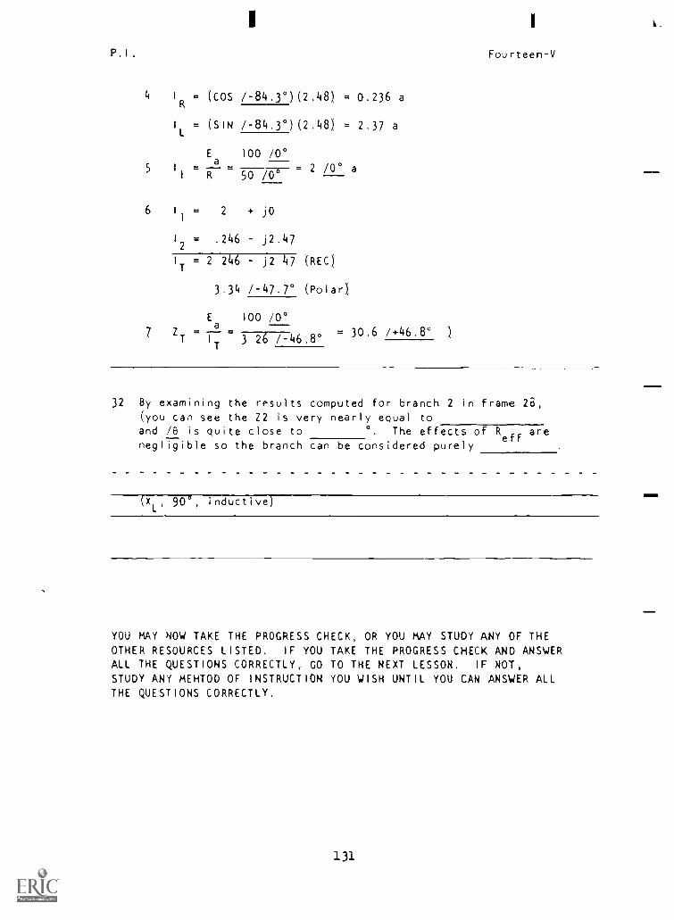
P.1.
4 I
R
1
L
=
=
(COS
(SIN
/-84.3°)(2.48) =
=/-84.3°)(2.48)
5 1
1
Ea
R
100 /0°
2 /0° a=50 /0°
6 I
1
= 2 + j0
12 = .246 j2.47
I
T= 2 246 j2 47 (REC)
3.34 /-47.7° (Polar)
E 100 /0°
0.236 a
2.37 a
Z a = 30.6 /+46.8°T I
T3 26 /-46.8°
I
Fourteen-V
32 By examining the results computed for branch 2 in frame 28,
(you can see the Z2 is very nearly equal to
and /0 is quite close to °. The effects of Reff
are
negligible so the branch can be considered purely
(X , 90 , inductive)
YOU MAY NOW TAKE THE PROGRESS CHECK, OR YOU MAY STUDY ANY OF THEOTHER RESOURCES LISTED. IF YOU TAKE THE PROGRESS CHECK AND ANSWERALL THE QUESTIONS CORRECTLY, GO TO THE NEXT LESSON. IF NOT,
STUDY ANY MEHTOD OF INSTRUCTION YOU WISH UNTIL YOU CAN ANSWER ALLTHE QUESTIONS CORRECTLY.
131
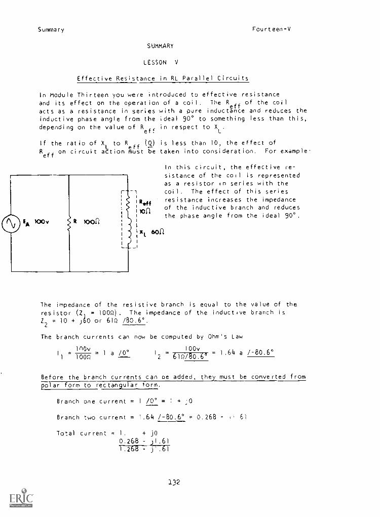
Summary Fourteen-V
SUMMARY
LESSON V
Effective Resistance in RL Parallel Circuits
In Module Thirteen you were introduced to effective resistanceand its effect on the operation of a coil. The R of the coil
acts as a resistance in series with a pure inductanceff e and reduces theinductive phase angle from the ideal 90° to something less than this,depending on the value of R
effin respect to X
L.
If the ratio of XL
to Reff
(Q) is less than 10, the effect of
Reff
on circuit action must be taken into consideration. For example.
r
loof1
In this circuit, the effective re-
sistance of the coil is representedas a resistor in series with the
_ coil. The effect of this seriesR144 resistance increases the impedance
10i1of the inductive branch and reducesthe phase angle from the ideal 90°.
xl 60n
The impedance of the resistive branch is equal to the value of the
resistor (2, = 100Q). The impedance of the inductive branch isZ2
= 10 + J60 or 61Q /80.6°.
The branch currents can now be computed by Ohm's Law
1nOv 100I
1 1000= 1 a /0° 12 61Q/80.v 66
1.64 a /-80.6°
Before the branch currents can oe added, they must be converted frompolar form to rectangular torm.
Branch one current = 1 /0° = 1 + JO
Branch two current = 1.64 /-80.6° = 0.268 l' 61
Total current = 1. + j0
0.268 J1.611.268 j1.61
132

Summary Fourteen-V
Total circuit current and circuit phase angle can now be found by
converting the rectangular representation for IT to polar form
I
T= 2 15 a /-51.8°
Recall that Q is determined by the ratio of reactance to resistanceX,
within the coil, Q =L
. A coil with a low XL
to Re
ratio has a
low Q and therefore cannot be regarded as a pure inducff tance.
As long as the Q of a coil remains 10 or above, the effect:ye re-sistance is considered negligible and the shift in /0 In the
inductive branch need not be considered. If the Q of the coil is
below 10, however, the effect of its resistance on the circuit is
significant and must be considered.
AT THIS POINT, YOU MAY TAKE THE LESSON PROGRESS CHECK, OR YOU MAYSTUDY THE LESSON NARRATIVE OR THE PROGRAMMED INSTRUCTION OR BOTH.IF YOU TAKE THE PROGRESS CHECK AND ANSWER ALL OF THE QUESTIONSCORRECTLY, GO TO THE NEXT LESSON IF NOT, STUDY ANOTHER METHOD OF
INSTRUCTION UNTIL YOU CAN ANSWER ALL THE QUESTIONS CORRECTLY.
133
1
NAVPERS 94558-I4a
BASIC ELECTRICITY AND CLECTRONICS
INDIVIDUALIZED LEARNING SYSTEM
MODULE FOURTEEN
LESSON VI
Parallel Resonance Experiments
Study Booklet
Bureau of Naval Personnel
January 1972
43Y/135
Overview Fourteen-VI
OVERVIEW
LESSON VI
Parallel Resonance Experiments
In this lesion you will conduct some experiments with a parallel
RCL circuit operating at a range of frequencies including the
resonant frequency
You will require
-NEAT Board 8
-Audio Signal Generator
-Multimeter
You will perform the following experiments
-determining fo by (LINE
-determining fo by lc and IL
-effects of changing Q
-effect of f
oof varying C
BEFORE YOU START THIS LESSON, PREVIEW THE LIST OF STUDY RESOURCES
ON THE NEXT PAGE.
136
Study Resources Fourteen-VI
LIST OF STUDY RESOURCES
LESSON VI
Parallel Resonance Experiments
Since this lesson consists of experiments, there is only the narrative
There are no other study resources and no progress checks.
TURN THE PAGE AND BEGIN THE NARRATIVE.
137
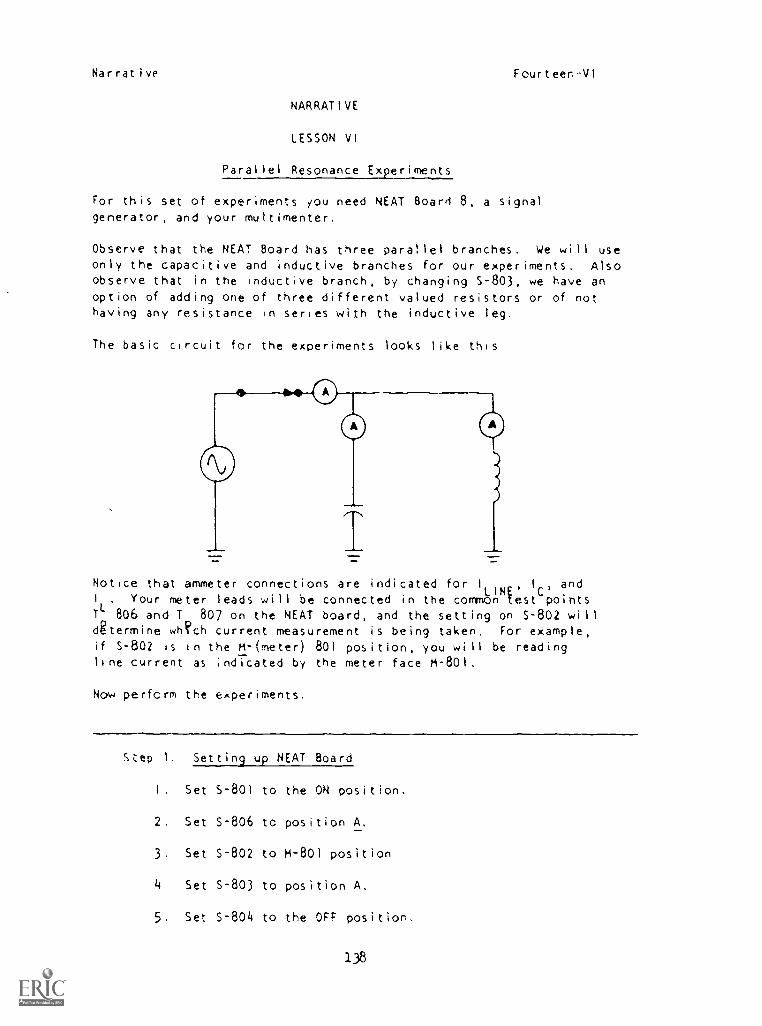
Narrative Fourteen VI
NARRATIVE
LESSON VI
Parallel Resonance Experiments
For this set of experiments you need NEAT Board 8, a signalgenerator, and your multimenter.
Observe that the NEAT Board has three parallel branches. We will useonly the capacitive and inductive branches for our experiments. Alsoobserve that in the inductive branch, by changing S-803, we have anoption of adding one of three different valued resistors or of nothaving any resistance in series with the inductive leg.
The basic circuit for the experiments looks like this
Notice that ammeter connections are indicated for I
LINE'I
C'and
I . Your meter leads will be connected in the common test pointsTL
806 and T 807 on the NEAT board, and the setting on S-802 willatermine wh?ch current measurement is being taken. For example,if S-802 is in the M-(meter) 801 position, you will be readingline current as indicated by the meter face M-801.
Now perform the experiments.
Step I. Setting up NEAT Board
I. Set 5-801 to the ON position.
2. Set S-806 to position A.
3. Set S-802 to M-801 position
4 Set S-803 to position A.
5. Set S-804 to the OFF position.
138
Narrative Fourteen-VI
Step 2. Setting Up Audio Signal Generator
Put bard selector in position C
2 Select sine wave position
3. Turn frequency control all the way counterclockwise.
4, Turn amplitude control all the way clockwise,
5 Plug in signal generator and turn on power switch. (Thered power-available light should glow.) Allow a fewminutes for warm-up.
6. Connect test leads to output jacks (black to bottomterminal).
7. Insert other end of test leads to NEAT board terminalsTP
-802 and TP-803 (black to T
P-803).
Step 3. Setting Up Simpson 260
1. Set up Simpson to read DC current on 10 ma scale.
2. Insert test leads from Simpson to terminals T -806 andT -807 (black to T -806). pP P
Experiment I Determining fo by(LINE
Step 1. Slowly raise the frequency control of the signal generatorand observe tne current reading on the meter.
Step 2 By manipulating the frequency control, tune the signalgenerator to the frequency where line current isminimum and keep it there. This is f
o.
What does the range dial indicate resonant frequency tobe?
If frequency is varied above or below./ f
o, does I
INEin-
crease or decrease?
Notice fo
is approximately 4.2 KHz. I
LNEincreases when applied
frequency varies either above or belowL
t
o,
. .111
13?
Narrative Fourteen-VI
Experiment 2 Determining fo by lc and I
Step I Switch S-802 to H-802 position. You will now be readingIC.
Stcp 2
Record reading
Switch S-802 to H-803 position. You will now be readingIL.
Record reading
What condition exists when IL equals IC?
What other circuit quantities must be equal in
order for I
Lto equal 1
C'?
IC = approximately 3 47 ma
IL = approximately 3 47 ma
When IL and I are equal, resonance exists.
In an Ideal tank, if IL equals I
Cthen XL equals X
c
Experiment 3 Changing Q
Step 1 Put S-802 back to the H-801 position, You arereading I
LINEagain Tune signal jeneratcr again to
ensure you are still at f
o
Step 2 While switching S-803 from position A to position B,C, and D to add different values of resistance, notethe meter reading at each position.
Has I
LINEincreased or decreased?
In what position is resistance greatest?
In what position is Q lowest?
In what position is (LINE greatest?
-L1.10
Narrative Fourteen-VI
LINEincreased
Resistance is greatest in position O.
Q is lowest in position D.
I
LINEis greatest in position D.
Step 3 Place S-803 back to position A.
Experiment 4 Changing fo by Varying Capacitance
Step 1 Place S-806 in position B.
Step 2. This places variable capacitor C-80I in the circuit.Turn C-801 fully counterclockwise.
Step 3 Adjust signal generator until 1 is minimumWhat is new f 7
LINE
o
Step 4 Adjust C-801 to center or midrange position.
Step Adjust signal generator until 1 is minimumWhat is new f 7
LINE
0
Step 6. Adjust C-801 fully clockwise.
Step 7 Adjust signal generator for minimum line current.
Step 8 Record new f
?3.5 KHz,. i8 KHz, 25 KHz
NOTE When adjusting for m.nimum I
LINE'down scale multimeter
as you approach 0 I
LINE'
In
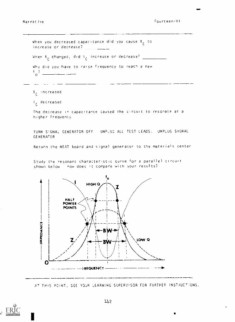
Narrative Fourteen-VI
When you decreased capacitance did you cause Xc to
increase or decrease?
When XCchanged, did I
Cincrease or decrease?
Why did you have to raise frequency to reach a newf
o?
XC
increased
I
Cdecreased
The decrease in capacitance caused the circuit to resonate at a
higher frequency
TURN SIGNAL GENERATOR OFF UNPLUG ALL TEST LEADS. UNPLUG SIGNAL
GENERATOR
Return the NEAT board and signal generator to the materials center
Study the resonant characteristic curve for a parallel circuit
shown below How does it compare with your results?
I
fo
1
HIGH 0
7.-
O
HALFPOWERPOINTS
S,1
\\/ \/ \
Z / 40.4 \ LON/ 0\ \
/ I I
I 1
1
I
\... " 1' .------------ t.RIO4A NC Y
...N...._....._m..
AT THIS POINT, SEE YOUR LEARNING SUPERVISOR FOR FURTHER INSTAUCTIONS.

Apper,dixBEST COPY AVAILABLE
1--- /.6f1(71-
1Je !,,,e1 0 c,,
0 :0 0 2" u 3' r lu
0
1
2
3
4
5
6
7
8
9
10
12
ts:nCO3tan
bln
COStan
Sin
costan
Si fl
COS
Is n
al nCON
tan
:oncobtan
51 1
CC)tan
31nCOS
t7111
SInCO3
tan
snCOS
tan
51 n
. OS
15n
sl ncosto n
S n
cos1.3 n
Fourteen
0 0000 0 0017 0 001 0 0052 0 0075 10
I 0000 1 0000 1 009" i 0000 , 0600 1
0 0000 0 00.7 9 003 C 00-'2 0 0070 0
0 0175 0 0191 0 0209 0 OW 0 0244 0
0 9998 0 9998 .) 9,',1 0 9997 0 5917 0
0 0175 0 019, 0 0205 0 0227 0 0244 0
0 0349 0 0366 0 0384 0 0401 0 6419 0
0 9991 0 9993 0 9093 0 9992 0 9091 0
0 0349 0 0167 0 01114 0 0102 0 0'119 0
0 0523 0 0541 0 10''8 J 2576 0 0593 0
0 99S6 0 9985 0 9984 0 9983 0 9982 0
0 0524 0 0542 0 0550 0 05/7 0 0594 0
0 0698 0 0715 0 0732 0 0750 0 0760 0
0 9976 0 9974 0 9`1%3 0 9970 3 9971 0
0 0699 0 0717 0 0734 0 0752 0 0739 0
0 0872 0 0889 0 000' 0 0924 ) 094' 0
0 9962 0 9960 0 9951 0 9957 0 9050 0
0 0875 0 0892 0 0910 0 0928 0 0945 0
0 1045 0 1063 0 1067 C 1097 0 1:15 0
0 9945 0 9943 0 9942 0 9910 0 5018 0
0 1051 0 1069 0 1080 0 1104 U 1122 0
0 1219 0 1236 0 1253 0 12/1 0 :233 0
0 9925 0 9923 0 9921 0 0919 0 9917 0
0 1228 0 1246 0 12()3 C 1261 0 1299 0
0 1392 0 1409 0 1426 0 1444 0 1191 0
0 9903 0 °900 0 9898 0 989; 0 0693 0
0 1405 0 1423 0 1411 0 1459 0 1 17 0
0 1564 0 1582 0 1559 0 1.16 0 '(91 o
0 9677 0 9374 0 9671 0 0369 0 911. 6 0
0 1584 0 1602 C 1020 0 1631; 0 1.)5 0
0 1736 0 1754 0 1771 0 188 o 1805 0
0 1840 0 9845 0 9842 0 9839 0 '383,, 0
0 1763 0 1781 0 1799 0 1817 0 101, 0
0 1904 0 1925 0 1942 0 1,54 0 1977 ;
0 9815 0 9513 0 9P1C 0 9806 0 9503 0
0 1947 0 1962 0 1980 0 1910', 0 4016 0
0 2079 0 200f, 0 2113 0 2170 0.7 47 C
0 )781 0 .1779 0 9774 0 3170 0, n7 0
0 '126 0 0) 41 0 21',2 0 2'00 0 _,09 0
0 22'0 0 227 n 271 0 ,'",;(, 0 z1:, 0
51 97,4 0 '3710 0 57-t ,) ,' 0 172t i',
''' 301 : 33, 0 2 31", (I e , 1 3Si t.
() 0' 0 1 n
..._
., ' ik.
s.n
13 ' 's1 a ,
T.dc 2_2. )
113
, s° 0 6° 0 7" 0 8° 0 90
0067 0 0105 0 0122 0 0140 0 0157
3003 0 0°99 0 9599 0 9099 0 9799
0087 0 0105 0 0,22 0 0140 0 0157
0262 o 0275 0 0297 0 0314 0 033e
c:^07 J 979n 0 9996 C 9095 0 9995
0261 0 0079 0 0297 0 0314 0 0332
0436 0 0454 0 04/1 0 0188 0 0506
0990 9090 0 9989 0 9968 0 9987
0477 6. 0454 0 0472 0 0489 0 u507
0610 0 0628 0 0645 0 003 0 0680
9981 0 9980 0 9979 0 9978 0 9977
0012 0 0629 0 064/ 0 Ot 61 0 0o82
0785 0 U802 0 0819 0 0837 0 0854
99u° U 99u8 0 9966 0 99j5 0 99630787 0 0805 0 08/2 0 0840 0 0857
0953 0 0976 0 0993 0 1011 0 10231
9054 0 9952 0 9951 0 9949 0 Q947
0903 0 0081 0 0998 0 1016 0 1033
1132 0 1149 0 1167 0 1134 0 1201
91936 0 9934 0 9932 0 9030 0 °923
1139 0 1157 0 1175 0 1192 0 1210
.305 G 1323 0 1340 0 1357 7 1374
0914 0 7912 0 9910 0 3907 r 9905
1317 0 1334 0 1352 0 '370 0 '388
1478 0 1495 0 1513 0 '530 0 1547
9'00 0 °888 0 9685 0 9882 0 98814°5 '3 1512 0 1530 0 1518 0 1566
1650 0 1668 0 1685 0 1702 0 1719
0863 0 98(0 0 9857 0 9654 0 9251
1671 0 1691 0 1709 0 172", 0 174',
18:2 0 1840 0 1357 0 1874 0 1601
3333 0 0829 0 9)026 0 9323 0 9820
1353 0 1871 0 1890 0 1908 0 1026
'99, 0 20:1 0 2028 0 204; 0 20n2
9751 0 996 0 1;92 0 9789 0 9755
70,5 0 2053 0 2071 0 2089 0 210-
21,4 0 2181 0 2198 0 2215 0 02321
976, C 9759 0 975' 0 9731 0 9748
2.1' 0 2235 0 2051 0 2272 0 24001
213: 3 2351 0 ,11(,3 0 2385 0 2402
'74 0 °7'0 0 '17', 0 9711 0 071)7
4",) 0 019 0. _134_0 2.:),,,, 3_ IL,' ' 1
0 0 i'° C 7° n 1, 0 00
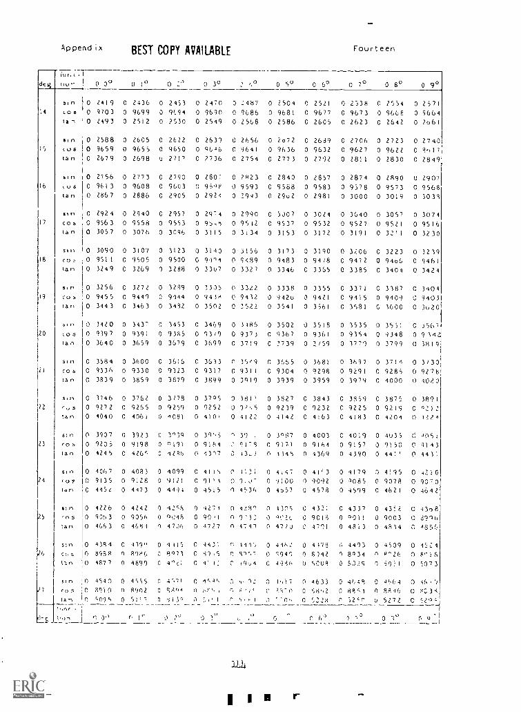
Append ix
0 0°
BEST COPY AVAILABLE Four teen
deg 0 1° 0 2° 0 3° 0 so 0 69 0 7° 0 8° 0 9°
3111 0 2419 0 2436 0 2453 0 2470 0 2467 0 2504 0 2521 0 2538 0 2554 0 2571CO 0 0 9703 0 9699 0 9194 0 9690 0 9086 0 9681 0 9677 0 9673 0 9608 0 9664ta- 0 2493 0 2512 0 2530 0 2549 0 2568 0 2586 0 2605 0 2623 0 2642 0 2061
sIn 0 2588 0 2605 0 2622 0 2630 0 2650 0 2672 0 2689 0 2706 0 2723 0 2740IS (us 0 9659 0 9655 0 9650 0 9046 0 9641 0 9636 0 9632 0 9627 0 9622 0 9()17
tan 0 2679 0 2698 0 271/ 0 2736 0 2754 0 2773 0 2792 0 2811 0 2830 0 2849
n 0 2756 0 2773 0 2790 0 2807 0 2823 0 2840 0 2857 0 2874 0 2890 0 290716 (us 0 9613 0 9608 0 9603 0 95 oe 0 9593 0 9568 0 9583 0 9578 0 9573 0 9568
tan 0 2867 0 2886 0 2905 0 2924 0 2943 0 2962 0 2981 0 3000 0 3019 0 3033
stn 0 2924 0 2940 0 2957 0 2974 0 2990 0 3J07 0 3024 0 36,40 0 3057 0 307417 CO b 0 9563 0 9558 0 9553 0 95,8 0 9542 0 9537 0 9532 0 9527 0 9521 0 9516
tan 0 3057 0 3076 0 3096 0 3115 0 3134 0 3153 0 3172 0 3191 0 32'1 0 3230
Si II 0 3090 0 3107 0 3123 0 3140 0 3156 0 3173 0 3190 0 3206 0 3223 0 323918 co :- 0 9511 0 9505 0 9500 C 91°4 0 9489 0 9483 0 9478 0 9472 0 9460 0 9461
tan 0 3249 0 3269 0 3288 0 33u7 0 3327 0 3346 0 3365 0 3385 0 3404 0 3424
s.n 0 3256 0 3272 0 3289 0 1305 0 3322 0 3338 0 3355 0 3371 C 3387 0 340219 c(3 0 9455 0 9449 0 9144 0 9438 0 9432 0 9420 0 9421 0 9415 0 9409 0 9403
tan 0 3443 0 3463 0 3432 0 3502 0 3522 0 3541 0 3561 0 3581 G 1600 0 3020
511, 0 3420 0 3437 0 3453 0 3469 0 3260 0 3502 0 3518 0 3535 0 3551 0 356120 cos 0 9397 0 9391 0 9385 0 93/9 0 9373 0 9367 0 9361 0 9354 0 9348 0 99421
tan 0 3640 0 3659 0 3679 0 3699 0 3719 0 2739 0 3(59 0 1770 0 3799 0 3819
sln 0 3584 0 3600 0 3616 0 3633 n 36e9 0 3655 0 3681 0 3697 0 3711 0 3/3021 cos 0 9336 0 9330 0 9323 0 9317 0 9311 0 9304 0 9298 0 9291 0 9285 0 9278
tan 0 3839 0 3859 0 3879 0 3899 0 3019 0 3939 0 3959 0 3979 0 4000 0 4020
Sin 0 3746 0 3762 0 3/78 0 3705 0 381' 0 3827 0 3843 0 3859 0 3875 0 389122 cc, 5 0 9272 0 9265 0 9259 0 9252 0 0 9239 0 9232 0 9225 0 9219 0 0212
tan 0 4040 0 4061 0 4081 0 410' 0 4122 0 4142 0 4163 0 4183 0 4204 0 2224
sln 0 3907 o 3923 0 3°31 0 39'5 n 39 . 0 3081 0 4003 C 1019 0 4035 J05123 CO 0 9208 0 9198 0 o191 0 9184 9179 0 9171 0 9164 0 9157 0 9150 0 4143
ta 0 4245 0 426c 0 4286 0 '.317 0 43-7 0 4349 0 4369 0 4390 0 441' 0 441;
sln 0 4067 0 4083 0 4099 0 4115 0 0 4,47 0 41(3 0 4179 0 4195 0 421024 c0 ? 0 9135 0 9128 0 9121 0 91'1 9.o7 0 9100 0 902 0 -1085 0 9078 0 9070
tan 0 4452 0 4473 0 4492 0 4515 0 4536 0 4>51 0 4578 0 4599 0 4621 0 4642
%In 0 4226 0 4242 0 42;9 0 4274 0 433l O 4105 0 4321 0 4337 0 4332.. 0 43o825 '-o5 0 9063 0 9056 0 0048 0 90,1 n 2'3: 0 902L 0 9018 0 0011 0 9003 0 010
tan 0 4663 0 4681 0 4706 0 4727 n 4717 0 47/0 4701 0 4813 0 4834 C 485t,
SIts 0 4384 0 499" 0 4415 0 4431 1416 0 4462 0 4178 6 4493 0 4509 0 152426 0 89,58 n 8980 0 23073 0 1'1,5 n 44(.7 0 4944 0 8)42 0 8034 n 8'26 0 8°18
trirl 0 4877 0 4899 0 4°41 0 22 491,4 C 49i6 0 8C08 0 5029 0 50::1 0 6073
slr, 1) 4540 0 4555 0 4;71 0 154 CC 4, 02 0 0,17 0 4633 0 4644 0 4564 0 16,127 cos 0 8910 0 8902 0 9806 0 ,C.4, 4711 0 0 88c1 0 8816 0 8038
tan n (095 0 5117 n -513,) r 0., 0 5328 0 52(n u 5272 C1,1nr
ri-Q JI)n '. O'' r, )` 0 l`'J , I, ,) 0 0 6'7 1 /3 0 1 o
r
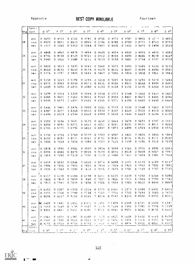
Leg
Appendix
(uric-
tton
28
29
incostan
sin
cos:an
stn
30 costan
sin
31 costan
stn
32 cos
tan
stn
33 costan
sin
cos34
tan
35
3E,
stn
costan
stn
costan
sin
costan
stn
38 cos
tan
stn
39 ccs
tan
41
deg,
51n
costan
slo
cos
tan(one -;ion
BEST COPY AVAILABLE Fourteen
0 o" 0 1° 0 20 0 3° 0 4° 0 S° 0 60 0 70 0 80 0 9°
0 4695 0 4710 0 4726 0 4741 0 4756 0 4772 0 4787 0 4802 0 4e'1 0 4833
0 8829 0 8821 0 8813 0 8805 0 8796 0 8788 0 8780 0 8771 0 8763 0 8755
0 '317 0 5340 0 5362 0 5384 0 5407 0 5430 0 5452 0 5475 0 5498 0 5520
0 4848 0 4863 0 4879 0 4894 0 4909 0 4924 0 4939 0 4955 0 4970 0 4985
0 8746 0 8738 0 8749 0 8721 0 8712 0 8704 0 8695 0 8686 0 8678 0 8669
0 5543 0 5566 0 5589 0 561e 0 5635 0 5658 0 5661 0 5'04 0 5727 0 5750
0 5000 0 5015 0 5030 0 5045 0 5060 0 5075 0 5090 0 5105 0 5120 0 5135
0 8660 0 8652 0 8643 0 8634 0 8625 0 8616 0 8607 0 8599 0 8590 0 8581
0 5774 0 5797 0 5820 0 5844 0 5867 0 5890 0 5914 0 5938 0 5961 0 5985
0 5150 0 5165 0 5180 0 5195 3 5210 0 5225 0 5240 0 5255 0 5270 0 5284
0 8572 0 8563 0 8554 0 85P3 0 8536 0 8526 0 8517 0 8508 0 8499 0 8490
0 6009 0 6032 0 6056 0 o080 U 6104 0 6128 0 6I5Z 0 6176 0 6200 0 6224
0 5299 0 5314 0 5329 0 5344 0 5358 0 5373 0 5388 0 5402 0 5417 0 5432
0 8480 0 8471 0 8462 0 3453 0 8.143 0 8434 0 842: 0 8415 0 8406 0 8396
0 6249 0 6273 C 62g7 0 6322 0 6346 0 6371 0 6395 0 6420 0 6445 0 64o9
0 5446 0 5461 0 5476 0 5490 0 5505 0 5519 0 5534 0 5548 0 5563 0 5577
0 8387 0 8377 0 8368 0 8358 0 833 C 8339 0 8329 0 e320 0 8310 0 8300
0 6494 0 6519 0 b544 0 65o9 0 6594 0 6619 0 6644 0 6669 0 6694 0 6720
0 5592 0 5606 0 5621 G 5635 0 5650 0 5864 0 5678 0 5693 0 5107 0 5721
0 8290 0 8281 0 8271 0 8261 0 8251 0 8441 0 6231 0 8221 0 8211 0 8202
0 6745 0 6771 0 6796 0 6822 0 6847 0 6873 0 6899 0 6924 0 6950 0 697o
0 5736 0 5750 0 5764 0 5770 0 5793 0 5807 0 5821 0 5835 0 5850 0 5364
0 8192 C 8181 0 8171 0 8161 0 8151 0 8141 0 8131 0 8121 0 8111 0 810C
0 7002 0 7028 0 '054 0 7080 0 7107 0 7133 0 7159 0 7186 0 7212 0 7239
0 5878 0 5892 0 5906 0 5920 0 5934 0 5948 0 5162 0 5976 0 5990 0 6004
0 8090 0 8080 0 8070 0 8059 0 8u49 0 803'i 0 8C28 0 8018 0 8007 0 7997
0 7265 0 7292 0 7319 0 734f, 0 7273 0 7400 0 742/ 0 7454 0 7481 0 7508
0 6018 0 6032 0 6046 0 6060 0 6074 0 6088 0 6101 0 6115 0 6129 0 614'
0 7986 0 7976 0 7965 0 7955 0 7914 0 7934 0 7923 0 7912 0 7902 0 7891
0 7536 0 7563 0 7590 0 7618 0 76r6 e 7673 0 7701 0 7729 0 7757 0 7755
0 6157 0 6170 0 6184 0 6118 0 5211 0 6225 0 b239 C 6252 0 6266 0 6280
0 7880 0 78c,9 0 7859 0 ,8414 0 7637 0, 7826 0 7e15 0 7304 0 7793 0 7782
0 7813 0 7441 0 7869 0 7898 0 7926 0 7954 0 7983 0 8012 0 8040 0 8069
0 6293 0 6307 0 6320 0 6354 0 (347 0 6361 0 6371 0 6388 0 6401 0 6414
0 7771 0 7760 0 7749 0 7738 0 7727 ,710 0 7705 0 7694 0 7683 0 7672
0 8098 0 8127 0 8156 0 8185 9 8214 0 8243 0 827-3 0 8302 0 8332 0 8".61
6428 0 6441 0 )455 0 6:(6 o .,,11 .1 6494 0 6508 0 6521 0 6534 0 6547
0 7660 0 '649 0 '1 3S n 7,,27 0 15 0 7004 0 7593 0 7;81 0 7570 n 1559
0 8391 0 8421 C F'461 0 8,81 5;11 0 8541 0 R571 0 8601 0 8632 0 boo::
0 6561 0 6574 0 6i87 0 6600 C J 3 0 662:. 0 6639 0 6652 C 66o5 0 64,78
0 7547 0 753( 0 7524 0 7512 G 7,0' 0 74,k, C. 7478 0 71,.6 0 7755 0 -4730 8"n3 0 1.724 0 8751 ^ F 4i ,11, ( 5617 0 -v1,8 n Polo 0 8911 0 g)72
0 00 ^ 1') 0 0 30 0 in n ()° 0 7 0 8° 0 1°
1L5
---------------
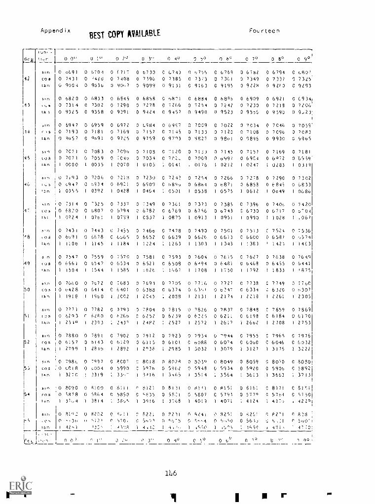
Appendix
1013, -l-e tt,..n 1
42
43
14
45
46
47
ea
49
50
51
52
53
154
stn 1
cos
tan
stn
s,1.IS
410rtan
stn
costan
stn
(,s
,3n
stn
cos
thn
s n
COS
An
n
co
Ian
$ M
(0515l1
uncostan
uncos
(An
uncos
In
810
n') ,...-
I 1 tanr---
I
BEST COPY AVAILABLEFourteen
0 0". 0 2° 0 3" 0 4° 0 7') 0 6° 0 7° 0 80 0 90
0 6691 0 6701 0 6717 0 0730 0 0743 0 6756 0 6769 0 6782 0 6794 0 680?
0 7431 0 1420 0 7408 0 7396 0 7385 0 7313 0 7301 0 7349 0 7337 0 73250 9004 0 9036 0 9067 0 9099 0 9131 0 9163 0 9195 0 9228 0 921-0 0 9293
0 6820 0 6833 0 6845 0 6858 0 6871 0 6884 0 68 °6 0 6909 0 6921 0 09340 7314 0 7302 0 7290 0 7278 0 7266 0 7254 0 7242 0 7230 0 7218 0 72060 9325 0 9358 0 9391 0 9424 0 9457 0 9430 0 9523 0 9576 0 9590 0 9,23
0 6947 0 6959 0 6972 0 6984 0 6957 0 7009 0 7022 0 7034 0 7046 0 70590 7193 0 7181 0 7169 0 7157 0 7145 0 7133 3 7120 0 7108 0 7096 0 70830 9657 0 9691 0 9725 0 9759 0 9793 0 9827 0 98o1 0 9896 0 9930 0 9965
0 7071 0 7083 0 7096 0 7103 0 7120 0 71;3 0 7145 0 7157 0 7169 0 71810 7071 0 7059 0 704o 0 7034 0 7n2- 0 7009 0 0901 0 6904 0 6072 0 0959I 0000 1 0035 I 0070 I 0105 I 0141 1 0176 1 0212 1 0247 I 0283 I 0319
0 7,93 0 7206 0 7313 0 7230 0 724? 0 7254 0 7266 0 7278 0 7290 0 73020 6917 0 6931 0 6931 0 6909 0 6896 0 6864 0 6871 0 6858 0 6845 0 68331 0355 1 0392 1 0428 I 0464 0501 1 0538 I 0575 1 0612 I 0o49 1 0686
0 7314 0 '325 0 7337 0 7349 0 7361 0 7373 0 7385 0 7396 0 7406 0 74200 0820 0 6807 0 6794 C 6782 0 6769 0 6756 0 o743 0 6730 0 6717 0 0-041 0724 1 0761 1 0731 1 0337 1 0875 1 0913 1 0951 I 0990 1 1028 1 ,067
0 7431 0 7443 0 7455 0 746o 0 7478 0 7490 0 7501 0 7513 C 7524 0 75360 6691 0 6678 0 6665 0 6652 0 6639 0 6626 0 6613 0 6600 0 6587 0 6571
1 1106 I 1145 1 1184 1 1224 1 1263 I 1303 1 1343 I :383 ( 1423 1 1463
0 7547 0 7559 0 7570 0 7581 0 7593 0 7604 0 7615 0 7627 0 7638 0 7649
0 6561 0 6547 0 6534 0 6521 0 6508 0 6494 0 6481 0 6468 0 6455 0 6441
1 1504 1 1544 1 1585 1 1626 1 1 1708 1 1750 1 1792 1 1833 1 1875
0 7660 0 7672 0 7683 0 7691 0 7705 0 7716 0 7727 0 7738 0 7749 3 770C0 0428 0 6414 0 6401 0 6388 0 6374 0 6361 0 6.217 0 6334 1 6320 0 63071 1918 1 1960 1 2002 1 2045 I 2038 1 2131 1 2174 1 2218 1 2261 1 2305
0 7771 0 7782 0 7,793 0 7804 0 7815 0 7826 0 7837 0 7848 0 7859 0 78690 6293 C 6e80 0 6266 0 6252 0 6239 0 6225 0 6211 0 6198 0 6184 0 61701 2310 1 2393 1 243' 1 2482 1 2527 1 2572 1 2617 1 26o2 I 2/08 1 2753
0 7880 0 7891 0 7902 0 7912 0 7923 0 7934 0 '944 0 7955 0 7965 0 79760 6157 0 b143 0 6129 0 61)5 0 6101 0 0086 0 60'4 0 6060 0 6046 0 60321 2799 1 261b 1 2892 1 2938 1 2985 1 3032 1 3079 1 3127 1 3175 1 3222
0 798c 0 7097 0 8007 0 8018 0 6024 0 3019 0 8049 0 8059 0 8070 0 S0300 6018 0 6001 0 5990 C 5976 0 5902 0 5948 0 5934 0 5920 0 5906 C 58921 3270 I 3319 1 33,- 1 3416 1 3465 1 3514 1 3564 1 3613 1 3663 1 3713
0 8090 0 8100 0 8111 n 8121 0 8131 0 8111 0 4151 0 6161 0 8171 C 8151
0 5878 0 5864 0 5850 0 '835 0 5821 3 SSO7 0 5791 0 5770 0 57o4 0 57501 37c,4 1 3814 1 36.,S 1 3916 1 3768 1 4013 1 4071 1 4124 417, 1 922°
0 81',2 0 82172 0 8 ll 0 822) 0 8211 n 6241 1' 8251 0 8251 0 P2'1 0 828
0 '.30 u 5721 0 570. 0 56'17 0 ',6-8 0 '..-0,4 0 5,,S0 0 561, 0 S ,.:1 n 500'1 12,1 12.7,' 1 41':S 1 4,t2 1 4,1, 1 1',50 1 15^5 1 14,59 1 lil 1 4770
1116
Ir P M
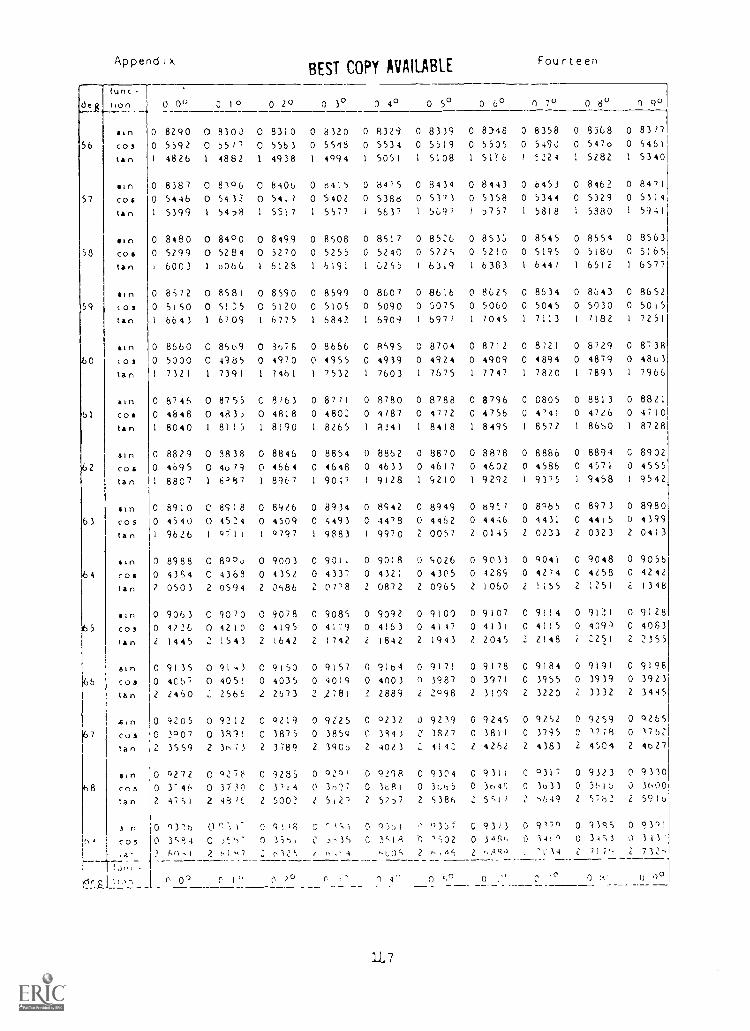
AppendixBEST COPY AVAILABLE
Fourteen
(unc-
tion
sin
56 I
co,
tan
sincos
tan
gin58 cos
tan
sin59 (03
tan
stn60 cos
tan
11171
61 cos
tan
sincostan
gin63 cos
tan
sincostan
aln
cosan
gin
66 CO3
tan
sin
costan
stn68 cos
tan
3 n
h' cos,a-
0 0° 3 10 0 2° 0 3° 0 4° 0 5° 0 6° 0 7° 0 8°
0 8290 0 8300 0 83)0 0 8320 0 8329 0 8339 0 8)48 3 8358 0 8368 0
0 5592 0 5577 0 5563 0 5518 0 5534 0 5519 0 5505 0 5490 0 547o 0
1 4826 1 4882 1 4938 1 4994 1 5051 1 5108 1 51'(6 1 5224 1 5282 1
0 8387 0 8196 0 8406 0 8415 0 84'5 0 8434 0 8443 0 8453 0 8462 0
0 5446 0 5432 0 5417 0 5402 0 5388 0 5373 0 5358 0 5344 0 5329 0
I 5399 1 54,8 1 5517 1 5577 1 5637 1 5697 1 5757 1 5818 1 5880 1
0 8480 0 84 °0 0 8499 0 8508 0 8517 0 8526 0 8533 0 8545 0 8554 0
0 5299 0 5284 0 5270 0 5255 0 5240 0 5225 0 5210 0 5195 0 5180 0
i 6003 1 0066 1 6123 1 6191 1 6255 1 6319 1 6383 1 6447 1 6512 1
0 8572 0 8581 0 8590 0 8599 0 8607 0 8616 0 8625 0 8634 0 8643 0
0 5150 0 511:5 0 5120 0 5105 0 5090 0 5075 0 5060 0 5045 0 5030 0
1 6643 1 6709 1 6775 1 6842 1 6909 1 6977 1 7045 1 7113 1 7182 1
0 8660 0 8669 0 3676 0 8666 0 8595 C 8704 0 8712 0 8721 0 6729 0
0 5000 0 4385 0 4970 0 4955 0 4939 0 4924 0 4909 0 4894 0 4879 0
1 7321 1 7391 1 7461 1 7532 1 7603 1 7675 1 7747 1 7820 I 7893 1
0 8746 0 8755 0 8763 0 8771 0 8780 0 8788 0 8796 C 0805 0 8813 0
0 4848 0 483) 0 4818 0 4803 0 4787 0 4772 0 4756 0 4'41 0 4726 0
1 8040 I 8115 1 8190 1 8265 1 8341 I 8418 1 8495 1 8572 1 8650 1
0 8829 0 9838 0 8846 0 8854 0 8862 0 8870 0 8878 0 8886 0 8894 C
0 4695 0 4u79 0 4664 0 4648 0 4633 0 4617 0 4602 0 4586 0 4571 0
1 8807 1 8497 1 8967 1 9047 I 9)28 I S2I0 I 9292 I 9375 1 9458 1
0 8910 0 8318 0 8926 0 8934 0 8442 0 8949 0 69:7 0 8065 0 8973 0
0 4540 0 4534 0 4509 0 4493 0 4478 0 4462 0 4446 0 4431 0 4415 0
1 9626 1 9711 1 0797 1 9883 1 9970 2 0057 2 0145 2 0233 2 0323 2
0 8988 0 800J 0 9003 0 9011 0 9018 0 5026 0 9033 0 9041 0 9048 0
0 4364 0 4369 0 4352 0 4337 0 4321 0 4305 0 4289 0 4274 0 4258 0
2 0503 2 0594 2 0586 2 07'8 2 0872 2 0965 2 1060 2 1155 2 1251 2
0 9063 0 9070 0 9078 0 9085 0 9092 0 9100 0 9107 0 9114 0 9121 0
0 4226 0 4210 0 4195 0 4179 0 4163 0 4177 0 4131 0 4115 0 109 0
2 1445 2 1543 2 1642 2 1742 2 1842 2 1943 2. 2045 2 2148 i 2251 2
0 9135 0 91,3 0 9150 0 9157 0 9164 0 9171 0 9178 0 9184 0 9191 0
0 4C67 0 4051 0 4035 0 4019 0 4003 o 3987 0 3971 0 3955 0 3939 0
2 2460 2566 2 2673 2 )781 2 2889 2 2098 2 3109 2 3220 2 3332 2
0 9205 0 9212 0 9219 0 9225 0 0232 0 9239 0 9245 0 9252 0 9259 0
0 3007 0 3891 0 3875 0 3859 0 3843 3827 0 3811 0 3795 C 3778 0
2 3559 2 3N73 2 3789 2 3905 2 4023 2_ 4142 2 4262 2 4383 2 4504 2
0 0272 0 0,278 0 928 0 020' 0 9298 0 9304 0 9311 0 0317 0 9323 0
0 3-46 0 3130 0 3714 0 3,),?7 0 3181 0 3665 0 3645 0 3533 0 361:, 0
2 4751 2 49 %f, 2 5002 2 5,2-) 2 57,7 2 5386 2 5c17 2 ',649 2 5762 2
0 03.16 0 0 93,6 C 0 93:,1 ' °367 0 93/3 0 9170 0 9188 0
0 3S94 C n C C 351,4 0 3417, 0 140 0 34;3 3
3 50-,1
r, 0°
2 0147
C I'012',
0 ?"
2 4
r
,Los
r) 4'
2_,,4f,
0 0
2
0
-C14
C
71P.
0 :1'
2
0 9°
8317
5461
5340
8471
5314
5941
8563
5165
6577
865250157251
8738
48637966
8821
47108728
8902
4555
9542
89804399
0413
90564242
1348
91284063
2355
91983923
3445
92651762
4627
93303600
591 b
9301
313
712,
1
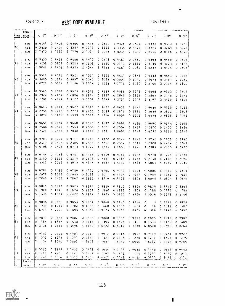
Appendix BEST COPY AVAILABLE Fourteen
func-
hun 0 0° 0 1° 0 2" 0 3° 0 4v 3 50 0 6° 0 7° 0 8° 0 9°
un 0 9397 0 9403 0 9409 0 9415 0 9421 0 ')42b 0 9432 0 9438 0 9444 0 944970 cos 3420 0 3404 0 3387 0 3371 0 3355 0 3338 0 3322 0 3305 0 3289 0 3272
tan 2 7475 2 7625 2 7776 2 7929 2 8083 2 8239 2 8397 2 8556 2 8716 2 8878
stn 0 9455 C 9461 0 9466 0 94'2 0 9478 0 9483 0 9489 0 9494 0 9500 0 9505cos 0 3256 0 3239 0 3223 0 3206 0 3190 0 3173 0 3156 0 3140 0 3123 0 3107Ian 2 9042 2 9208 2 9375 2 9544 Z 9714 2 9887 3 0061 3 0237 3 0415 3 0595
nn 0 9511 0 9516 0 9521 0 0527 0 9532 0 9537 0 9542 0 9548 0 9553 0 9558'72 COS 0 3090 9 3074 0 3057 0 3040 0 3024 0 3007 0 2990 0 2974 0 2957 0 2940
tan 3 0777 3 0961 3 1146 3 1334 3 1524 3 1716 3 1910 3 2106 3 2305 3 2506
510 0 9563 0 9568 0 9573 0 9578 0 9583 0 9588 0 9593 0 9598 0 9603 G 9608CO3 0 2924 0 2907 2 2890 0 2874 0 2857 0 2840 0 2823 0 2807 0 2790 0 2773ten 3 2709 3 2914 3 3122 3 3332 3 3544 3 3759 3 3977 3 4197 3 4420 3 4640
0 9613 0 9617 0 9622 0 9627 0 9632 0 9636 0 9641 0 9646 0 9650 0 965574 C05 0 2756 0 2740 0 273 0 2706 0 2689 0 2672 0 2656 0 2639 0 2622 0 2605
an 3 4874 3 5105 3 5339 3 5576 3 5816 3 6059 3 6305 3 6554 3 6806 3 7062
0 9659 0 9664 0 9668 0 9673 0 9677 0 9681 0 9686 0 9690 0 9691 0 969975 COS 0 2588 0 2571 0 2554 0 2538 0 2521 0 2504 0 2487 0 2470 0 2453 0 2436
tan 3 7321 3 7583 3 7843 3 8118 3 8391 3 8667 3 8947 3 9232 3 9520 3 9812
un 0 9703 0 9707 0 9711 0 9715 0 9720 0 9724 0 9728 0 9732 0 9736 0 9740
6 cos 0 2419 0 2402 0 2385 0 2368 0 2351 0 2334 0 2317 0 2300 0 2284 0 2267tan 4 0108 4 0408 4 0713 4 1022 4 1335 4 1653 4 1976 4 2303 4 2615 4 2972
Stn 0 9744 0 9748 0 9751 0 9755 0 9759 0 9763 0 9767 0 9770 0 9774 0 9778'77 coS 0 2250 0 2232 0 2215 0 2198 0 2181 0 2164 0 2147 0 2130 0 2113 0 2096
tan 4 3315 4 3662 4 4015 4 4374 4 4737 4 5107 4 5483 4 5864 4 0252 4 6E46
stn 0 9781 0 9785 0 9789 0 9792 0 9796 0 9799 0 9803 0 9806 0 9810 0 9813"73 cos 0 2079 0 2062 0 2045 0 2028 0 2011 0 1994 0 1977 0 1959 0 1942 0 1925
an 4 7046 4 7453 4 7867 4 8288 4 8716 4 9152 4 9594 5 0045 5 0504 5 0970
btn 0 9816 0 9820 0 9823 0 9826 0 9829 0 9833 0 9836 0 0839 0 9842 0 9845cos 0 1908 0 1891 0 18/4 0 1857 0 1840 0 1822 0 1805 0 1788 0 1771 0 1754tan 5 1446 5 1929 5 2422 5 2924 5 3435 5 3953 5 4486 5 5026 5 5578 5 6140
s,n 0 9848 0 9851 0 9854 0 9857 0 9860 0 98b3 0 9866 0 J 0 9871 0 9874cos 0 1736 0 1719 0 1702 0 1685 0 1668 0 1650 0 1633 0 16 0 1599 0 1582tar 5 6713 5 7297 5 7894 5 8502 5 9124 5 9758 6 0405 6 J66 6 1742 6 2432
sm 0 9877 0 9880 0 9882 0 9885 0 9888 0 9890 0 9893 0 9895 0 9898 0 0909cos 0 1564 1 1547 0 1530 0 1513 0 1495 0 1478 0 1461 0 1444 0 )426 0 1401tan 6 3138 6 3859 6 4596 6 5350 b 6122 6 6912 6 7720 6 8548 6 93°5 7 0264
1
un 0 9903 0 9905 0 9°07 0 9910 n 191? 0 9914 0 9917 0 9919 0 9921 0 99231cos 0 1312 0 1374 0 1357 0 1340 0 1323 C 1305 0 1288 0 1271 0 1253 0 12'.5
1
Ian 7 1154 7 2066 7 3002 7 391,2 7 447 ? 595.3 7 6996 7 8062 7 9158 8 0285
sty 0 0225 0 992A ^ 093C 0 09'2 0 1931 0 901h 0 0938 0 9940 0 9912 0 994383 cos 0 i21) n itoi I l r l 0 11,-; r) 1 161 o t ') '115 0 1007 0 1050 0 10, 1,
P 1443 A k 1M(3 3 ni27 -M3 '4, 01 51 q 0570 9 2^:2 9 3')72,
) 0° 0 1° 0 .1,) C o 7 n n 0°1
1118
I
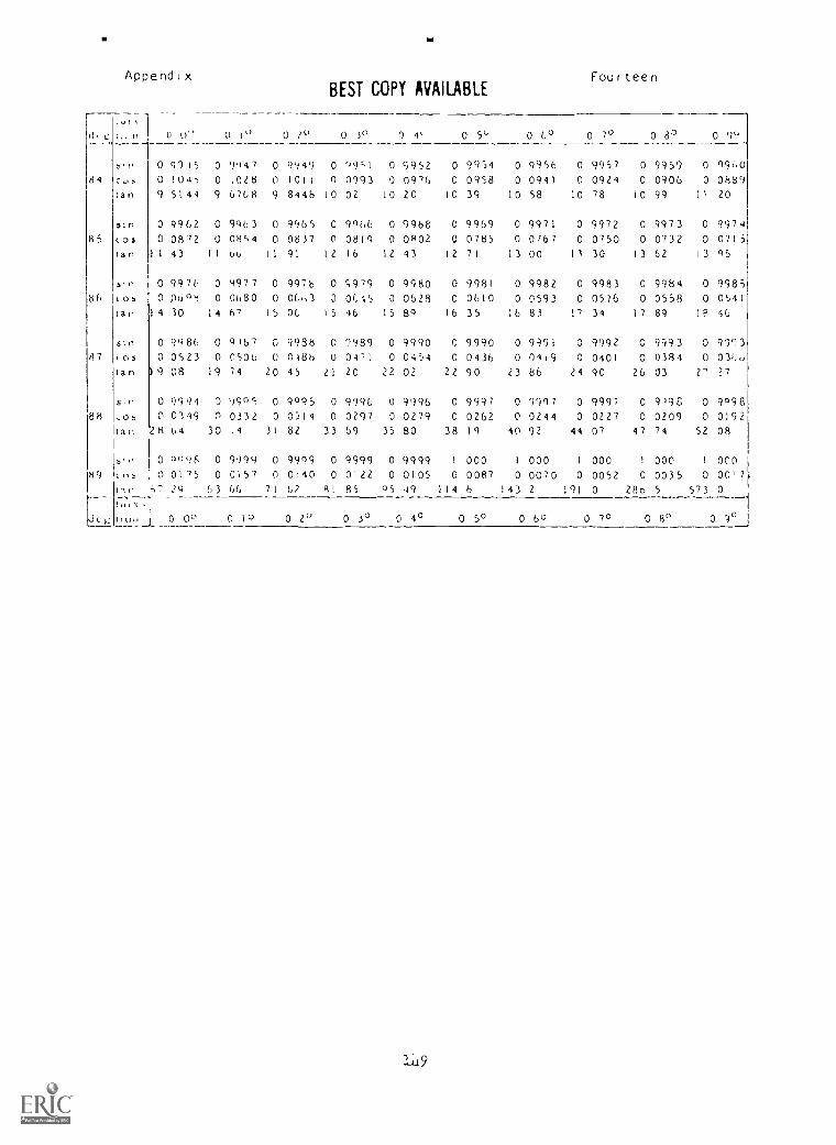
Appendix Four teenBEST COPY AVAILABLE
1,
A. c kik n 0 o"
0 9'315 0
0 I" 0 20
9949 0
0 3"
99;1
0
0
4'
<3952
0 5° 0 CO 0 7° 0a' 0 9°
9'147 0 0 9954 0 0956 0 9957 0 9959 0 096084 CJh 0 1045 0 1028 0 toll n 0993 0 0976 0 0958 0 0941 0 0924 0 0906 0 0889
an 9 5144 9 6768 9 844b lo oz 10 20 10 39 10 58 10 78 10 99 It 20
ein 0 9962 0 9963 0 9965 C 9'466 0 9968 0 9969 0 9971 0 9972 0 9973 0 9974R5 CO3 0 0872 0 0854 0 0837 0 0819 0 0802 0 07135 0 0767 0 0750 0 0732 0 0715
tan I 43 II 66 II 91 12 16 12 43 12 71 13 00 11 30 13 62 13 Q5
Sin 0 9976 0 9977 0 9976 0 5979 0 9980 0 9981 0 9982 0 9983 0 9984 0 998586 cos 0,06,08 0 0680 0 06,,3 0 0615 0 0628 0 0610 0 0593 0 0576 0 0558 0 0541
an 4 30 14 6' 15 OC 15 46 15 80 16 35 16 83 17 34 17 89 IP 46
sin 0 9086 0 8167 G 9938 0 9989 0 9990 0 9990 0 9991 0 9992 0 9993 0 999387 ,c35 0 0523 0 050b 0 0486 0 04'1 0 0454 0 0436 0 0419 C 0401 0 0384 0 03i,c,
tan 9 08 19 74 20 45 LI 20 22 02 22 90 23 86 24 90 26 03 2' 27
sin 0 9091 0 '3905 0 9°95 0 9996 0 9996 0 9997 0 9997 0 9997 0 9198 0 909888 cc3 Il 0 0119 0 0331 0 0314 0 0297 0 0279 0 0262 0 0244 0 0227 0 0209 0 0192
tar, 28 64 30 14 31 82 33 69 35 80 38 19 40 92 44 07 47 74 52 08
s)., 0 0996 0 9909 0 9099 0 9999 0 9999 1 000 I 000 I 000 1 000 I 000R9 (,-s 0 0175 0 0157 0 0140 0 0122 0 0105 0 0087 0 0070 0 0052 0 0035 0 0017
ilo 57 2Q 63 66 71 67 RI 85 05 49 114 6 143 2 191 0 288 5 573 0
.icy 110.1 0 00 0 10 0 2° 0 3° 0 40 0 5° 0 60 0 7° 0 8° 0 9°
119