Embed Size (px)
Citation preview

Module 4 : Deflection of Structures
Lecture 3 : Principle of Virtual Work
Objectives In this course you will learn the following
Computation of deflection using principle of virtual work ( PVW ).
Application to pin-jointed structure.
Application of PVW to beams and frames.
Simplified PVW for beams and frames using multiplication of bending moment diagram.
4.4 Principle of Virtual Work
Consider a structural system subjected to a set of forces ( … referred as P force) under stableequilibrium condition as shown in Figure 4.11(a). Further, consider a small element within the structuralsystem and stresses on the surfaces caused by the P forces are shown in Figure 4.11(b) and referred as .
Let the body undergoes to a set of compatible virtual displacement . These displacements are imaginaryand fictitious as shown by dotted line. While the body is displaced, the real forces acting on the body movethrough these displacements. These forces and virtual displacements must satisfy the principle ofconservation of energy i.e.
(4.8)
(4.9)
This is the principle of virtual work
If a system in equilibrium under a system of forces undergoes a deformation, the work done bythe external forces ( P ) equals the work done by the internal stresses due to those forces, ( ).
In order to use the above principle for practical applications, we have to interchange the role of the forcesand displacement. Let the structure acted upon by a virtual force is subjected to real displacements then theEq. (4.9) can be written as
(4.10)
This is the principle of complimentary virtual work and used for computing displacements.
Consider a structure shown in Figure 4.12(a) and subjected to P force and it is required to find thedisplacement of point C in the direction specified. First apply a virtual force at C in the required
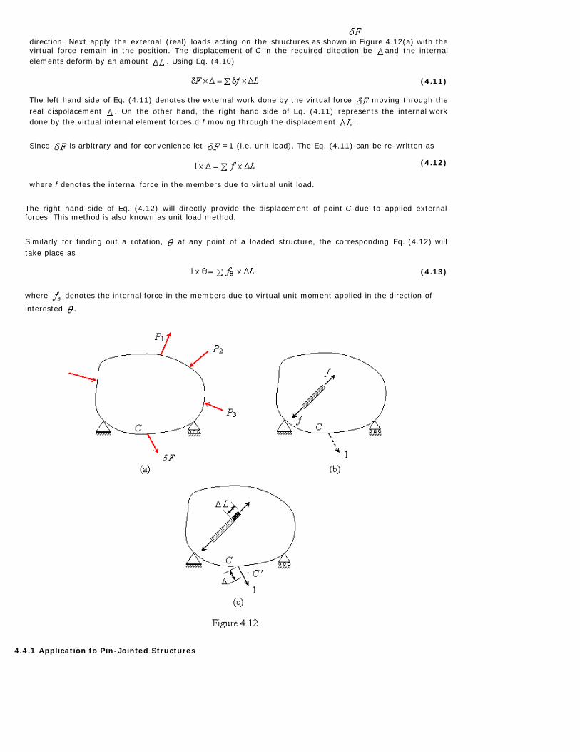
direction. Next apply the external (real) loads acting on the structures as shown in Figure 4.12(a) with thevirtual force remain in the position. The displacement of C in the required ditection be and the internalelements deform by an amount . Using Eq. (4.10)
(4.11)
The left hand side of Eq. (4.11) denotes the external work done by the virtual force moving through thereal dispolacement . On the other hand, the right hand side of Eq. (4.11) represents the internal workdone by the virtual internal element forces d f moving through the displacement .
Since is arbitrary and for convenience let =1 (i.e. unit load). The Eq. (4.11) can be re-written as
(4.12)
where f denotes the internal force in the members due to virtual unit load.
The right hand side of Eq. (4.12) will directly provide the displacement of point C due to applied externalforces. This method is also known as unit load method.
Similarly for finding out a rotation, at any point of a loaded structure, the corresponding Eq. (4.12) willtake place as
(4.13)
where denotes the internal force in the members due to virtual unit moment applied in the direction of
interested .
4.4.1 Application to Pin-Jointed Structures

Consider a pin-jointed structure as shown in Figure 4.13 and subjected to external force P 1 , P 2 and P 3 .Let the vertical displacement of point C , is required. Under the action of the real external load, let
the axial force in typical member be and therefore, the deformation of the member ( Land AE are the length and axial rigidity of typical member).
Apply a unit vertical load at C and substituting in Eq. (4.12) leads to
(4.14)
The basic steps to be followed for finding the displacements of the pin-jointed structure are
1. Compute the axial force in various members (i.e. ) due to applied external forces.
2. Compute the axial force in various members (i.e. ) due to unit load applied in the direction ofrequired displacement of the point.
3. Compute the product for all members.
4. The summation will provide the desired displacement.
5. The axial force shall be taken as positive if tensile and negative if compressive.
6. The positive implies that the desired displacement is in the direction of applied unit load
and negative quantity will indicate that the desired displacement is in the opposite direction of theapplied unit laod.
Example 4.9 Find the horizontal and vertical deflection at joint C of the pin-jointed frame shown in Figure4.14. AE is constant for all members.

Solution: Calculate forces i.e. force in various members of the truss due to the applied loading. These
can be obtained by considering the equilibrium of various joints as marked in Figure 4.14(b).
Table 4.2
Member LengthFor For
L L
AB L -P 0 0 0 0BC L 0 0 0 0 0CD L -P -1 PL -1 PLDA L 0 0 0 0 0
AC 0 0

The computation of for two desired displacements of pin-jointed frame are shown in Table 4.2.
Horizontal displacement of joint C ,
Vertical displacement of joint C ,
Example 4.10 For the pin-jointed structure shown in the Figure 4.15, find the horizontal and verticaldisplacement of the joint D . The area of cross-section, A =500 and E =200,000 for all themembers.
Solution: The axial rigidity of the members, kN. The computation of thedesired displacements is presented in Table 4.3
Table 4.3
Member Length L(m)For For
L L
AB 2 1920 0 0
BC 2 480 0 0
CD 2 480 0 0
DE 2 120 1 -
EF 2 - 1080 1 -
CE 2 - - 480 0 0
BF 2 480 0 0
The horizontal deflection of = 55.2 mm
The vertical deflection of = - 8.31 mm = 8.31 mm
4.4.2Application to beams and frames
In order to find out the vertical displacement of C of the beam shown in Figure 4.16(a), apply a unit loadas shown in Figure 4.16(b).

The internal virtual work is considered mainly due to bending and caused due to internal moments
under going the rotation due to the applied loading. (internal virtual work done by shearing forces and
axial forces is small in comparison to the bending moments and hence ignored). Since the
where is the moment due to applied loading, the Eq. (4.12) for the displacement of C will take a shape
of
(4.15)
The basic steps to be followed for finding the displacement or slope of a beams and frames are summarizedas
1. Compute the bending moment (i.e. ) due to applied external forces.
2. Compute the bending moment (i.e. ) due to unit load applied in the direction of requireddisplacement or slope.
3. Compute the integral over the entire members of the beam or frame which will
provide the desired displacement.4. The bending moment shall be taken as positive if sagging and negative if hogging (in case of
beams).
5. The positive implies that the desired displacement is in the direction of applied unit
load and negative quantity will indicate that the desired displacement is in the opposite direction ofthe applied unit load.
Example 4.11 Determine the slope and deflection of point A of the cantilever beam AB with length L andconstant flexural rigidity EI.
Solution: Deflection under the Load - Apply a vertical unit load at point A of the beam as shown in Figure4.17(b). Consider any point X at a distance of x from A ,
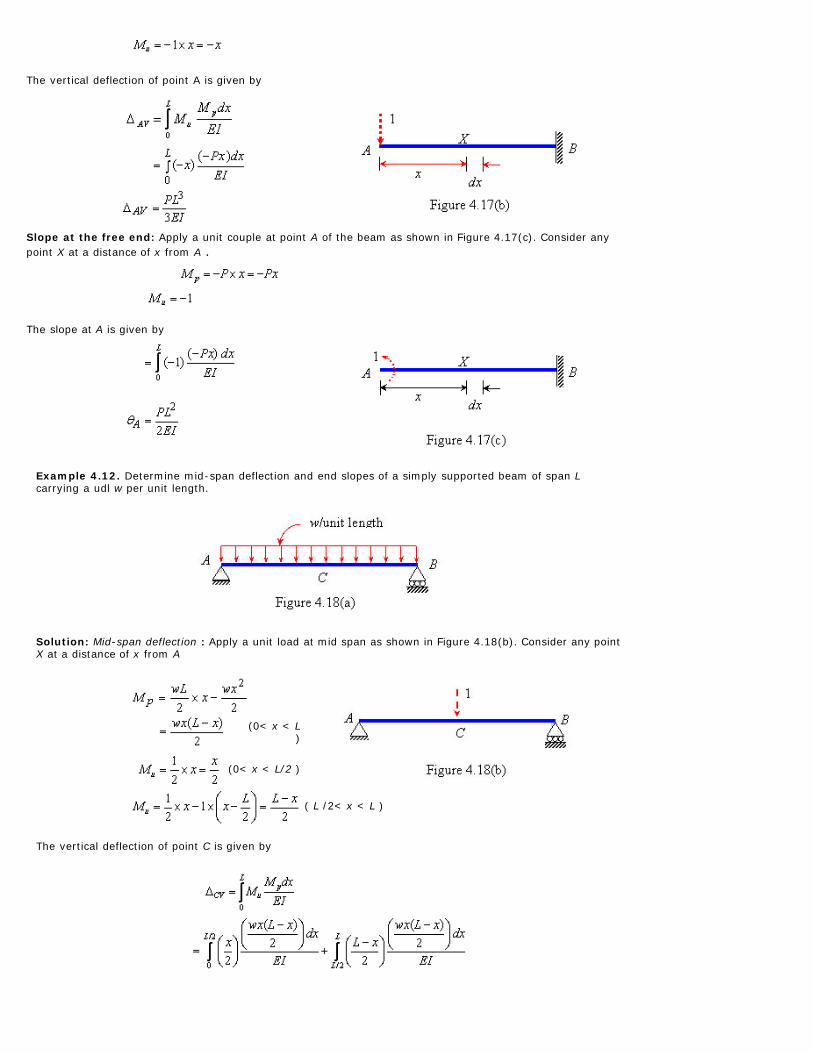
The vertical deflection of point A is given by
Slope at the free end: Apply a unit couple at point A of the beam as shown in Figure 4.17(c). Consider anypoint X at a distance of x from A .
The slope at A is given by
Example 4.12. Determine mid-span deflection and end slopes of a simply supported beam of span Lcarrying a udl w per unit length.
Solution: Mid-span deflection : Apply a unit load at mid span as shown in Figure 4.18(b). Consider any pointX at a distance of x from A
(0< x < L)
(0< x < L/2 )
( L /2< x < L )
The vertical deflection of point C is given by

End slopes : Applying a unit couple at A as shown in Figure 4.18(c). Consider any point X at a distance of xfrom A
(0< x < L )
(0< x < L/2 )
The slope at A is given by
Due to symmetry (anti-clockwise direction)
Example 4.13 Determine vertical deflection and rotation of point B of the beam shown in Figure 4.19(a).The beam is subjected to a couple at C .
Solution: Vertical deflection of B : Apply a unit load at B as shown in Figure 4.19(b). Consider any point X ata distance of x from C
(0< x < a + b )
(0< x < b )
= (b < x < a + b)
The vertical deflection of point B is given by

(i.e. in the upward direction)
Rotation of B : Apply a unit couple at B as shown in Figure 4.19(c). Consider any point X at a distance of xfrom C
(0< x < a + b )
(0< x < a + b )
The rotation of point B is given by
Example 4.14. Determine horizontal deflection of C and slope at A of a rigid-jointed plane frame as shownin Figure 4.20(a). Both members of the frame have same flexural rigidity, EI .
Solution: Horizontal deflection of C : Apply a unit load C as shown in Figure 4.20(b).
Consider AB : ( x measured A )
Consider BC : ( x measured C )

The horizontal deflection of point C is given by
Rotation at A : Applying a couple at A as shown in Figure 4.20(d).
Consider AB : ( x measured A )
Consider BC : ( x measured C )
The slope at A is given by
4.4.3Moment diagrams multiplication method for beams and frames

Recall the Eq. (4.15) in which the bending deflection of the beams and frames are obtained by theintegration of the two bending moments variations (i.e. and ) over a length of the members.However, for a uniform beam section (i.e. EI is constant) such integrals can be readily derived depending
upon the various shapes of the bending moment diagrams. The computation of integral is
given in the Table 4.A1. The various steps for this method for finding deflections of the beams and frameare:
1. Draw the bending moment diagram of given beam or frame due to applied external loading (i.e. diagram).
2. Draw the corresponding bending moment diagram due to unit load applied in the direction ofinterested deflection (i.e. diagram).
3. Compute the desired deflection by computing the with the help of results shown in
Table 4.A1.
Example 4.15 Determine the deflection under the load and point D of a simply supported beam withoverhang as shown in Figure 4.21
Figure 4.21
Solution: Bending moment diagram (i.e. diagram) due to concentrated load W is shown in Figure4.21(b).
Deflection under the Load : Apply a vertical unit load in place of W . The bending moment diagram due tothis load is shown in Figure 4.21(c). The vertical deflection under the load is obtained by multiplying thebending moment diagrams of Figure 4.21(b) and (c) and is given by
(refer Table 4.A1)

Deflection of the free end : Apply a unit vertical load acting upward at point D of the beam. The bendingmoment diagram due to this load is shown in Figure 4.21(d). The vertical deflection under the load isobtained by multiplying the bending moments diagrams of Figure 4.21(b) and (d) and is given by
(refer Table 4.A1)
Example 4.16 Using the diagram multiplication method, determine the deflection under the load and endslopes of a non-prismatic simply supported beam.
Solution: Bending moment (B.M.) diagram (i.e. diagram) due to concentrated load W on the beam isshown in Figure 4.22(b).
Mid-span deflection : Apply a unit load in the downward direction at C . Deflection at C is given by multiplyingthe diagrams of Figure 4.22 (b) and (c) as follows
Slope at A : Apply a unit couple at A acting in the clockwise direction and plot the bending moment diagramof the beam as shown in Figure 4.22(d). The slope at A is given by multiplying the diagrams of Figure 4.22(b) and (d) as follows

(clockwise direction)
Slope at B : Apply a unit couple at B acting in the anti-clockwise direction and plot the bending momentdiagram of the beam as shown in Figure 4.22(e). The slope at B is given by multiplying the diagrams ofFigure 4.22 (b) and (e) as follows
Example 4.17 Using the diagram multiplication method, determine the horizontal displacement and rotaionof point C of the rigid-jointed plane frame shown in Figure 4.23. Both the members of the frame have sameEI value.
Solution: The free-body and bending moment diagram (B.M.D.) of the frame due to applied loading areshown in Figures 4.23(b) and (c), respectively.
Horizontal deflection of C : Apply a horizontal force at C as shown in Figure 4.23(d) and plot the bendingmoment diagram as shown in Figure 4.23(e). The horizontal deflection at C is given by multiplying thediagrams of Figure 4.22 (c) and (e) as follows

Rotation of C : Apply a unit couple at C as shown in Figure 4.23(f) and plot the bending moment diagram asshown in Figure 4.23(g). The slope at C is given by multiplying the diagrams of Figure 4.22 (c) and (g) as follows
(anti-clockwise direction)
Recap In this course you have learnt the following
Computation of deflection using principle of virtual work ( PVW ).
Application to pin-jointed structure.
Application of PVW to beams and frames.
Simplified PVW for beams and frames using multiplication of bending moment diagram.

Table 4.A1 Evaluation of the integral
KiL 1/2 KiL 1/2 K L 2/3 KiL 2/3 KiL 1/3 KiL 1/2 KiL
1/2 KiL 1/3 KiL 1/6 K L 1/3 KiL 5/12 KiL 1/4 KiL 1/6(1 + a ) KiL
1/2 KiL 1/6 KiL 1/6 K L 1/3 KiL 1/4 KiL 1/12 KiL 1/6(1 + b ) KiL
1/2 iL
1/6 iL
1/6
L
1/3 iL
1/12 iL
1/12 iL
1/6((1 + b ) +
(1 + a ) )iL
2/3 KiL 1/3 KiL 1/3 K L 8/15 KiL 7/15 KiL 1/5 KiL 1/3(1 + ab ) KiL
2/3 KiL 5/12 KiL 1/12 K L 7/15 KiL 8/15 KiL 3/10 KiL 1/12(5 - b - ) KiL
2/3 KiL 1/4 KiL 1/12 K L 7/15 KiL 11/30 KiL 2/15 KiL 1/12(5 - a - ) KiL
1/3 KiL 1/14 KiL 1/12 K L 1/5 KiL 3/10 KiL 1/5 KiL 1/12(1 + a + )KiL
1/3 KiL 1/12 KiL 1/12 K L 1/5 KiL 2/15 KiL 1/30 KiL 1/12(1 + b + )KiL
1/2 KiL 1/6(1+ a ) KiL1/6 KL ((1 + b )
+ (1 + a ) )
1/3(1 + ab )KiL
1/12(5 - b - ) KiL
1/12(1 + a + ) KiL 1/3 KiL


![INDEX [kgr.ac.in]kgr.ac.in/beta/wp-content/uploads/2018/09/Mechanics-of-Solids-Lab-Manual.pdf · inversely proportional to flexural rigidity (EI). Actual deflection so calculated](https://img.dokumen.tips/doc/110x75/5e07383467c8f14dad195cf7/index-kgracinkgracinbetawp-contentuploads201809mechanics-of-solids-lab-.jpg)


![Role of initial density distribution in simulations of ...modulus with the density via empirical expressions [6], an initial constant rigidity of the trabecular architec-ture is defined](https://img.dokumen.tips/doc/110x75/5e84d51868bc815354291991/role-of-initial-density-distribution-in-simulations-of-modulus-with-the-density.jpg)