Embed Size (px)
Citation preview

Earthquake geotechnical engineering practice
MODULE 3: Identification, assessment and mitigation of liquefaction hazards

DATE: May 2016 REvision: 0
MoDulE 3: idEntification, assEssMEnt and Mitigation of liquEfaction hazards
PagE b
3
Acknowledgements • Prof Misko cubrinovski (lead author) – university
of canterbury
• dr Kevin McManus (contributing author) – McManus geotech ltd
• Kevin anderson (contributing author) – aEcoM
NZGS Reviewers
• trevor Matuschka – Engineering geology ltd
• dr alexei Murashev – opus
• grant Murray – JgM associates
• tim sinclair – tonkin & taylor ltd
• ann Williams – beca ltd
International Reviewers
• Prof ross boulanger – university of california davis
• Prof Jonathan bray – university of california berkeley
Authors and reviewers of July 2010 NZGS Liquefaction Module (superseded)
EQC
NZGS/MBIE Editorial Panel
• refer Module 1
Document status
isbn: 978-0-947-497-33-0 (print) isbn: 978-0-947497-50-7 (online)
new zealand geotechnical society (nzgs) and Ministry of business innovation & Employment (MbiE) Earthquake geotechnical Engineering Practice in new zealand
rev 0
issue date May 2016
new Zealand Geotechnical society (nZGs) c/ institution of Professional Engineers new zealand Po box 12–241 Wellington 6013
Ministry of Business innovation & Employment (MBiE) building system Performance branch Po box 1473 Wellington 6140
this document published by the chief Executive of MbiE as guidance under section 175 of the building act 2004 to assist parties to comply with their obligations under the building act 2004.
it is not mandatory to follow the guidance, but if followed:
• it does not relieve any person of the obligation to consider any matter to which that information relates according to the circumstances of the particular case;
• users should consider taking appropriate professional advice prior to entering into a construction contract which incorporates all or parts of this document.
While the Ministry of business, innovation & Employment, MbiE, and the nzgs have taken care in preparing this document, it is only a guide and, if used, does not relieve any person of the obligation to consider any matter to which that information relates, according to the circumstances of the case. all users should satisfy themselves as to the applicability of the content and should not act on the basis of any matter contained in this document without considering, and if necessary, taking appropriate professional advice.
the document may be updated from time to time and the latest version is available from the Ministry’s website at www.building.govt.nz or the new zealand geotechnical society’s website at http://www.nzgs.org/publications/guidelines.htm.
important notice
this document is preliminary and the contents should be treated as draft guidelines. submissions by the geotechnical community to the society (email: [email protected]) are encouraged, after which a further review will be undertaken. the contents may be subject to further changes, additions, and deletions.
© Copyright
the copyright owner authorises reproduction of this work, in whole or in part, so long as no charge is made for the supply of copies, and the integrity and attribution of the contributors and publishers of the document is not interfered with in any way.

DATE: May 2016 REvision: 0
MoDulE 3: idEntification, assEssMEnt and Mitigation of liquEfaction hazards
PagE i
3 contents
ContentsPrefaCe ii
1 introduCtion 1
2 sCoPe 2
3 soil liquefaCtion hazard 3
3.1 ground shaking 3
3.2 liquefaction and lateral spreading 4
4 estimating ground motion Parameters 5
5 identifiCation and assessment of liquefaCtion hazards 6
5.1 site investigation and hazard identification 9
5.2 assessment of liquefaction susceptibility and triggering 12
5.3 liquefaction-induced ground deformation 18
5.4 residual strength of liquefied soils 23
5.5 Effects of liquefaction on structures 24
5.6 advanced numerical procedures 26
6 mitigation of liquefaCtion and lateral sPreading 27
6.1 soil remediation 28
6.2 structural modification 28
7 Clay soils 29
7.1 ground failure of clay soils 29
7.2 Mitigation of clay soils 29
8 VolCaniC soils 30
9 referenCes 31
aPPendix a. IMPoRtANt dIffERENCES BEtwEEN BouLANGER ANd IdRISS (2014) ANd IdRISS ANd BouLANGER (2008) MEthodS 34
DATE: May 2016 REvision: 0
MoDulE 3: idEntification, assEssMEnt and Mitigation of liquEfaction hazards
PagE ii
3preface
PrefaCethe sequence of strong earthquakes in canterbury in 2010 to 2011, most notably the devastating Mw 6.2 earthquake on 22 february 2011, the source of which was located within christchurch, resulted in 185 fatalities and extensive damage to buildings and infrastructure. liquefaction occurred on several occasions through the city and nearby areas. the damaging effects of this liquefaction included lateral spreading, settlement, foundation failures, subsidence of areas close to waterways, and large volumes of sediment ejecta on the ground surface.
the first edition of the liquefaction guidelines (formerly Module 1 of the Guidelines) was published in July 2010 shortly before the darfield earthquake of september 2010 and was well received and timely, considering the subsequent events. it proved very useful in guiding practice during a period when a very large number of liquefaction site assessments were carried out following the christchurch earthquakes and widespread liquefaction.
as a result of the earthquakes, the new zealand government established the canterbury Earthquakes royal commission (cErc) to consider the adequacy of current legal and best practice requirements for the design, construction, and maintenance of buildings in the context of earthquake risk. seven volumes of reports were published with 189 recommendations. of these recommendations, 175 sit with Ministry of business, innovation and Employment (MbiE) to execute with about 20 percent relating to geotechnical issues.
the cErc reports resulted in a large and critically important work programme for MbiE and this has included the development of more formal links with the engineering community. in 2014 MbiE signed a Memorandum of understanding with the new zealand geotechnical society (nzgs) to better align and create a shared understanding of each organisation’s objectives. it was also agreed to jointly update the existing guidelines module on liquefaction assessment to include latest developments resulting from the canterbury earthquakes and other major earthquakes worldwide and to accelerate the preparation of the additional modules of the guidelines.
in this first revision of the module on liquefaction assessment, some of the more general material contained in the original edition, including the general discussion of geotechnical earthquake hazards and estimating ground motion parameters has been moved to a new Module 1: Overview of earthquake geotechnical engineering practice guidelines for New Zealand. this new module explains the overall scope of the planned guidance documents, and contains an introduction to seismic hazards, fault rupture, ground shaking, liquefaction, and other hazards such as landslide and tsunami. it also contains information on the regulatory environment and geotechnical considerations for the built environment.
this first revision of the module on liquefaction assessment, now renamed Module 3, focusses on the identification, evaluation, and mitigation of liquefaction hazards. More detailed information on geotechnical investigations for liquefaction assessment purposes is covered in Module 2. More detailed information on the mitigation of liquefaction hazards by ground improvement is covered in Modules 5 and 5a, and on foundation design at sites with liquefaction in Module 4.
as a result of the 2010–2011 sequence of earthquakes in canterbury, there is a heightened risk of seismic activity within canterbury over the next few decades. the Verification Method b1/VM1 has been amended to reflect an increased seismic hazard factor for the canterbury earthquake region. these changes have been incorporated into the relevant sections of this document.
Charlie Price Mike Stannard chair chief Engineer new zealand Ministry of business geotechnical society innovation & Employment

DATE: May 2016 REvision: 0
MoDulE 3: idEntification, assEssMEnt and Mitigation of liquEfaction hazards
PagE 1
3 introduction
1 introduCtionnew zealand is a high earthquake hazard region and earthquake considerations are integral to the design of the built environment in new zealand. the effects of earthquake shaking need to always be considered in geotechnical engineering practice and frequently are found to govern design.
the high seismic hazard and profound relevance of geotechnical engineering were demonstrated in the canterbury earthquake sequence. christchurch and canterbury were hit hard by a series of strong earthquakes generated by previously unmapped faults located in the vicinity or within the city boundaries. in the period between 4 september 2010 and december 2011, the intense seismic activity produced the magnitude (Mw) 7.1 darfield event, the destructive 22 february 2011 Mw 6.2 earthquake, 12 other Mw 5 to 6 earthquakes, and over 100 Mw 4 to 5 earthquakes. the 22 february 2011 earthquake was the most devastating causing 185 fatalities, the collapse of two multi-storey buildings, and nearly total devastation of the central business district with approximately 70 percent of its buildings being damaged beyond economic repair. the total rebuild cost has been estimated to be nz$40 billion (nz treasury, 2014).
the geotechnical aspects and impacts of the earthquakes were of economic and societal significance. the canterbury earthquakes triggered widespread liquefaction in the eastern suburbs of christchurch, as well as rock slides, rock falls and cliff instabilities in the Port hills affecting tens of thousands of residential buildings, and causing extensive damage to the lifelines and infrastructure over much of the city. about half of the total economic loss could be attributed to the geotechnical impacts of the earthquake-induced liquefaction and rockslides.
the main aim of this guidance document is to promote consistency of approach to everyday engineering practice and, thus, improve geotechnical-earthquake aspects of the performance of the built environment. it is intended to provide sound guidelines to support rational design approaches for everyday situations, which are informed by latest research.
the science and practice of geotechnical earthquake engineering is advancing at a rapid rate. the users of this document should familiarise themselves with recent advances, and interpret and apply the recommendations herein appropriately as time passes.
this document is not intended to be a primer on soil liquefaction – readers are assumed to have a sound background in soil mechanics, earthquake engineering, and soil liquefaction theory, and to be qualified, professional geotechnical engineers.
neither is it a book of rules – users of the document are assumed to have sufficient knowledge and experience to apply professional judgement in interpreting and applying the recommendations contained herein.
this document is not intended to be a detailed treatise of latest research in geotechnical earthquake engineering, which continues to advance rapidly. complex and unusual situations are not covered. in these cases special or site-specific studies are considered more appropriate.

DATE: May 2016 REvision: 0
MoDulE 3: idEntification, assEssMEnt and Mitigation of liquEfaction hazards
PagE 2
3scope
2 sCoPethe material in this document relates specifically to earthquake hazards and should not be assumed to have wider applicability. it is intended to provide general guidance for geotechnical earthquake engineering practice with a particular focus on soil liquefaction and lateral spreading.
the recommendations in this document are intended to be applied to everyday engineering practice by qualified and experienced geotechnical engineers who are expected to also apply sound engineering judgement in adapting the recommendations to each particular situation. complex and unusual situations are not covered. in these cases special or site-specific studies are considered more appropriate.
other documents may provide more specific guidelines or rules for specialist structures, and these should, in general, take precedence over this document.
Examples include:
• New Zealand Society on Large Dams – Dam Safety Guidelines
• NZ Transport Agency – Bridge Manual
• Transpower – New Zealand Transmission Structure Foundation Manual.
Where significant discrepancies are identified among different guidelines and design manuals, it is the responsibility of the engineer to resolve such discrepancies as far as practicable.
the recommendations made in this document may seem excessive or burdensome for very small projects such as single unit dwellings. the intention is that liquefaction hazards should be properly investigated and assessed at the subdivision stage of development. then, simpler investigations and assessments would be adequate for individual sites. Professional judgement needs to be applied in all cases.
the topic of site investigation planning and procedures is covered briefly in this document. More detailed information is provided in Module 2 of the guidelines.
the topic of estimating ground motion parameters is covered briefly in this document. More detailed information is provided in Module 1 of the guidelines.
the topic of mitigation of liquefaction and lateral spreading is covered briefly in this document. More detailed information on ground improvement as mitigation is provided in Modules 5 and 5a of the guidelines. information on seismic design of foundations (including liquefaction) is provided in Module 4.

DATE: May 2016 REvision: 0
MoDulE 3: idEntification, assEssMEnt and Mitigation of liquEfaction hazards
PagE 3
3 soil liquefaction hazard
3 soil liquefaCtion hazardEarthquakes are sudden ruptures of the earth’s crust caused by accumulating stresses (elastic strain-energy) resulting from internal processes of the planet. ruptures propagate over approximately planar surfaces called faults releasing large amounts of strain energy. Energy radiates from the rupture as seismic waves. these waves are attenuated, refracted, and reflected as they travel through the earth, eventually reaching the surface where they cause ground shaking. surface waves (rayleigh and love waves) are generated where body waves (p-waves and s-waves) interact with the earth’s surface.
the principal geotechnical hazards associated with earthquakes are:
1 fault rupture
2 ground shaking
3 liquefaction and lateral spreading
4 landslides.
this Module of the guidelines is focussed on ground shaking and resulting ground damage, in particular liquefaction and lateral spreading.
3.1 ground shaking
ground shaking is one of the principal seismic hazards that can cause extensive damage to the built environment and failure of engineering systems over large areas. Earthquake loads and their effects on structures are directly related to the intensity, frequency content, and duration of ground shaking. similarly, the level of ground deformation, damage to earth structures and ground failures are closely related to the severity of ground shaking.
three characteristics of ground shaking are typically considered:
• amplitude
• frequency content
• duration of significant shaking (ie time over which the ground motion has significant amplitudes).

DATE: May 2016 REvision: 0
MoDulE 3: idEntification, assEssMEnt and Mitigation of liquEfaction hazards
PagE 4
3soil liquefaction hazard
these characteristics of ground motion at a given site are affected by numerous complex factors such as the source-to-site distance, earthquake magnitude, effects of local soil and rock conditions, rupture directivity, topographic and basin effects, source mechanism, and propagation path of seismic waves. there are many unknowns and uncertainties associated with these factors which in turn result in significant uncertainties regarding the characteristics of the ground motion and earthquake loads. hence, special care should be taken when evaluating the characteristics of ground shaking including due consideration of the importance of the structure and particular features of the adopted analysis procedure.
3.2 liquefaction and lateral spreading
the term ‘liquefaction’ is widely used to describe ground damage caused by earthquake shaking even though a number of different phenomena may cause such damage.
liquefaction is associated with significant loss of stiffness and strength in the liquefied soil, and consequent large ground deformation as a result of the development of large excess pore water pressures within the soil. Particularly damaging for engineering structures are cyclic ground movements during the period of shaking, and excessive residual deformations such as settlements of the ground and lateral spreads.
ground surface disruption including surface cracking, dislocation, ground distortion, slumping and permanent deformations, such as large settlements and lateral spreads, are commonly observed at liquefied sites. sand boils, including ejected water and fine particles of liquefied soils, are also typical manifestations of liquefaction at the ground surface. in the case of massive sand boils, gravel-size particles and even cobbles can be ejected on the ground surface due to seepage forces caused by high excess pore water pressures. note that sediment (silt, sand, gravel) ejecta are clear evidence of soil liquefaction, however they do not always occur at liquefied sites.
in sloping ground and backfills behind retaining structures in waterfront areas, liquefaction often results in large permanent ground displacements in the
down-slope direction or towards waterways (lateral spreads). in the case of very loose soils, liquefaction may affect the overall stability of the ground leading to catastrophic flow failures. dams, embankments and sloping ground near riverbanks where certain shear strength is required for stability under gravity loads are particularly prone to such failures.
clay soils may also suffer some loss of strength during shaking but are not subject to boils and other ‘classic’ liquefaction phenomena. however, for weak normally consolidated and lightly over-consolidated clay soils the undrained shear strength may be exceeded during shaking leading to accumulating shear strain and damaging ground deformations. if sufficient shear strain accumulates, sensitive soils may lose significant shear strength leading to slope failures, foundation failures, and settlement of loaded areas. ground deformations that arise from cyclic failure may range from relatively severe in natural quick clays (sensitivity greater than 8) to relatively minor in well-compacted or heavily over-consolidated clays (low sensitivity). studies by boulanger and idriss (2006, 2007), and bray and sancio (2006) provide useful insights. the summary in idriss and boulanger (2008) is helpful in clarifying issues and identifying adequate assessment procedures regarding soil liquefaction and cyclic softening of different soil types during strong ground shaking.
for intermediate soils, the transition from ‘sand-like’ to ‘clay-like’ behaviour depends primarily on the mineralogy of the fine-grained fraction of the soil and the role of the fines in the soil matrix. the fines content (fc) of the soil is of lesser importance than its clay mineralogy as characterised by the soil’s plasticity index (Pi). Engineering judgment based on good quality investigations and data interpretation should be used for classifying such soils as liquefiable or non-liquefiable. bray and sancio (2006), idriss and boulanger (2008), and other studies provide insights on the liquefaction susceptibility of fine-grained soils such as low plasticity silts and silty sands with high fines contents. if the soils are classified as ‘sand-like’ or liquefiable, then triggering and consequences of liquefaction should be evaluated using procedures discussed in this guideline document. on the other hand, if the soils are classified as ‘clay-like’ or non-liquefiable, then effects of cyclic softening and consequent ground deformation should be evaluated using separate procedures, which are referenced in section 7, but are not the subject of this document.

DATE: May 2016 REvision: 0
MoDulE 3: idEntification, assEssMEnt and Mitigation of liquEfaction hazards
PagE 5
3 estimating ground motion parameters
4 estimating ground motion ParametersEarthquakes occur on faults with a recurrence interval that depends on the rate of strain-energy accumulation. intervals vary from hundreds to tens of thousands of years. there is much uncertainty over the variability of the strain rate over time, the recurrence interval, the time since the last rupture, the activity of a fault, and the location of all active faults.
the ground shaking hazard at a site depends on the following parameters:
• amplitude, frequency content, and duration of shaking at bedrock beneath the site
• thickness and properties of soil strata beneath the site and overlying the bedrock, as well as bedrock properties themselves
• Proximity of the site to active faults (including near-fault effects)
• three-dimensional relief both of the surface contours and sub-strata.
for engineering evaluation of liquefaction phenomena, the amplitude (commonly represented by the largest value of acceleration recorded during the earthquake, ie the peak horizontal ground acceleration, amax) and the duration of ground shaking (related to earthquake magnitude, Mw) are the key input parameters to most common design procedures, with no direct consideration of the frequency (represented by the response spectrum).
the ground motion parameters at a site to be used for liquefaction hazard assessment may be evaluated using one of the following methods:
• Method 1: risk based method using the earthquake hazard presented in the nzta bridge Manual (2014)
• Method 2: site-specific probabilistic seismic hazard analysis (Psha)
• Method 3: site-specific response analysis.
Method 1 is appropriate for routine engineering design projects. Methods 2 and 3 are preferred for more significant projects, more complex sites, or other cases where advanced analysis can be justified.
a more detailed discussion of procedures for estimating ground motion parameters for geotechnical earthquake engineering purposes is provided in Module 1 of the guidelines.
for locations within the canterbury Earthquake region the following procedure is required:
Canterbury Earthquake Regionthe following recommended values of amax and effective earthquake magnitude, Mw for class d sites (deep and/or soft soil sites) within the canterbury earthquake region for liquefaction-triggering analysis only are given below. the annual probability of exceedance is considered to be the average over the next 50 years, considered appropriate for importance level 2 buildings.
sls amax = 0.13 g, Mw = 7.5 and amax = 0.19 g, Mw = 6
uls amax = 0.35 g, Mw7.5
for the sls, both combinations of amax and Mw must be analysed and the highest calculated total volumetric strain resulting from liquefaction under either scenario adopted (MbiE, 2014).
for class d sites outside of christchurch city and still within the canterbury Earthquake region, especially sites closer to the southern alps and foothills, it is recommended that design amax values be taken as the greater of these values and those from the nzta bridge Manual.
for sites other than class d within the canterbury Earthquake region, amax values should be derived using the nzta bridge Manual.
the above amax values have been developed specifically for liquefaction triggering assessments within the canterbury Earthquake region. they are not applicable for use in other geotechnical design procedures.
these values of amax have been classified as interim guidance by MbiE. the Ministry has advised that further, more comprehensive guidance may be given as a result of on-going model refinement. reference should be made to the MbiE website for the latest updates.

DATE: May 2016 REvision: 0
MoDulE 3: idEntification, assEssMEnt and Mitigation of liquEfaction hazards
PagE 6
3identification and assessment of liquefaction hazards
5 identifiCation and assessment of liquefaCtion hazards
cyclic behaviour of saturated soils during strong earthquakes is characterized by development of excess pore water pressures and consequent reduction in effective stress. in the extreme case, the effective stress may drop to zero or nearly zero (ie the excess pore water pressure reaches the initial effective overburden stress or the total pore water pressure rises to equal the total overburden stress) and the soil will liquefy. in these guidelines, liquefaction refers to the sudden loss in shear stiffness and strength of soils associated with the reduction in the effective stress due to pore water pressure generation during cyclic loading caused by an earthquake shaking.
the mechanism of pore water pressure build-up is governed by a contractive tendency of soils (or tendency to reduce in volume during shearing) under cyclic loading. When saturated soils are subjected to rapid earthquake loading, an immediate volume reduction in the soil skeleton is prevented by the presence of incompressible pore water and insufficient time for drainage to occur. the contractive tendency instead results in a build-up of excess pore water pressure and eventual liquefaction. in this context, loose granular soils are particularly susceptible to liquefaction because they are highly compressible and contractive under cyclic shearing due to the high volume of voids in their soil skeleton (particle arrangement/structure).

DATE: May 2016 REvision: 0
MoDulE 3: idEntification, assEssMEnt and Mitigation of liquEfaction hazards
PagE 7
3 identification and assessment of liquefaction hazards
it is important to emphasize at the outset of the discussion on liquefaction assessment that the rate of excess pore water pressure build-up, severity of liquefaction manifestation, and consequent ground deformation strongly depend on the density of the soil. in this context, one can identify ‘flow liquefaction’ as an extreme behaviour of very loose sandy soils in which a rapid pore water pressure build-up is associated with strain-softening behaviour and undrained instability (flow); flow liquefaction results in practically zero residual strength and extreme ground deformation. in loose to medium dense sands, liquefaction results in a (nearly) complete loss of effective stress and rapid development of strains in subsequent cycles of shear stresses. finally, dense sands exhibit transient liquefaction in which nearly zero-effective stress only temporarily occurs during cyclic mobility, which is associated with a gradual development of strains and limited deformational potential under cyclic loading.
these effects of soil density on the pore water pressure build-up, mechanism of strain development and consequences of liquefaction should be recognised and accounted for in the liquefaction assessment. the effects of density on the potential for liquefaction-induced ground deformation is illustrated in figure 5.1 where maximum shear strains associated with various combinations of cyclic stress ratios (csr) and penetration
resistances (𝑞𝑐1Ncs) are shown (idriss and boulanger, 2008). note that some of the maximum shear strain values in this figure 5.1 (corresponding to low penetration resistances) are overly conservative since they have been derived assuming presence of driving shear stresses associated with lateral spreading. the plot, however, clearly depicts the significant differences in the consequences of liquefaction (in terms of maximum shear strains or strain potential) for sand deposits with different densities (ie penetration resistances).
assessment of the liquefaction hazard and its effects on structures involves several steps using either simplified or detailed analysis procedures. these guidelines outline some of the available procedures and highlight important issues to consider when evaluating liquefaction susceptibility, triggering of liquefaction, liquefaction-induced ground deformation, and effects of liquefaction on structures. in this document, the term simplified (liquefaction evaluation) procedure is used to refer to state-of-the-practice semi-empirical methods for assessment of liquefaction susceptibility, liquefaction triggering, and liquefaction-induced ground deformation. figure 5.2 illustrates through flow-charts important factors to consider in the liquefaction assessment. remedial techniques for mitigation of liquefaction and its consequences are briefly addressed in section 6 of this guideline document.
Figure 5.1: Maximum shear strains for clean sands with M=7.5 and s’vc = 1 atm (Source: Idriss & Boulanger 2008)
cycl
ic s
tres
s r
atio
(csr
)
0.6Maximum shear
strains, gmax
100%
50%
20%
10%
5%
3.5% CRR RECoMMENdEd
by Idriss & Boulanger (2006) for clean sands
1%
0.5
0.4
0.3
0.2
0.1
050 100 150 200
normalized corrected cPt tip resistance – 𝑞𝑐1Ncs

DATE: May 2016 REvision: 0
MoDulE 3: idEntification, assEssMEnt and Mitigation of liquEfaction hazards
PagE 8
3identification and assessment of liquefaction hazards
Figure 5.2: Factors to consider in liquefaction vulnerability assessment
a Overview of simplified
liquefaction evaluation procedure
site characterisation and seismic hazard evaluation
liquefaction susceptibility
liquefaction triggering
liquefaction-induced ground deformation
Effects of liquefaction on structures
liquefaction mitigation
b Ground motion parameters, representative soil profile and liquefaction susceptibility (Sections 4, 5.1 and 5.2.1 of this module)
ground motion parameters (seismic hazard assessment: amax, Mw; de-aggregated magnitudes; amax and Mw pairs for scenario
earthquakes)
geology, geomorphology and geohydrology
subsoil stratigraphy and representative soil profile (soil type, thickness, index
properties, water table depth, borehole, cPt, sPt, Vs/Vp)
liquefaction susceptibility (Pi-based; Ic-based; age of soils,
depositional environment, paleo-liquefaction and other
historical evidence)
c Liquefaction triggering and liquefaction-induced ground deformation (Sections 5.2.2 and 5.3 of this module)
level ground conditions
liquefaction triggering (b&i, 2014)
Effects of fines content, Msf
uncertainties in GWL, amax, fc (CFC/Ic), PI/Ic
review and interpretation (critical layers, crust thickness and integrity, homogeneous or interlayered liquefied deposit,
severity of effects, land damage indices: LPI, LSN, …)
d Lateral spreading (Section 5.3.3 of this module)
lateral spreading
free face and topographic conditions; continuity of
critical layers; geologic evaluation
flow-deformation potential (in situ state/loads
vs. residual strength)
uncertainties in GWL, amax, fc (CFC/Ic), PI/Ic
spreading displacements: – Maximum ground displacement– zone affected by spreading– lateral and vertical distribution
within spreading zone (stretch, offsets)
e Effects on structures (Section 5.5 of this module)
quantify effects of liquefaction-induced ground deformation and earthquake
loads on deformation and damage to the structure
consider uncertainties in kinematic and inertial loads;
potential instability
location of structure and foundations in relation to
critical layer(s) (liquefaction source and manifestation);
impacts on services
Estimated performance versus desired performance for relevant return periods

DATE: May 2016 REvision: 0
MoDulE 3: idEntification, assEssMEnt and Mitigation of liquEfaction hazards
PagE 9
3 identification and assessment of liquefaction hazards
5.1 site investigation and hazard identification
this section covers site investigation for liquefaction assessment purposes. Module 2 provides guidance on earthquake geotechnical engineering ground investigation. sites to be developed as part of the built environment must be thoroughly investigated to allow identification and assessment of all geotechnical hazards, including liquefaction-related hazards. identification of liquefaction hazard at a site firstly requires a thorough investigation and sound understanding of the site geology, recent depositional history and geomorphology. the level of investigation should be appropriate to the geomorphology of the site, the scale of the proposed development, the importance of the facilities planned for the site, and the level of risk to people and property arising from structural failure and loss of amenity.
Most cases of soil liquefaction have occurred in relatively young deposits of poorly consolidated alluvial soils or fills with a high water table (saturated soils). typically, these are fluvial or constructed fill deposits laid down in a low energy environment and which are normally consolidated. such sites are often readily identifiable from a basic understanding of the regional geomorphology. typical sites where liquefaction has been observed include river meander and point bar deposits, lake shore delta deposits, estuarine deposits, beach ridge backwater deposits (beach ridge and dune deposits are usually of higher density and not as prone to liquefaction but may overlie backwater deposits), abandoned river channels, former pond, marsh or swamp, reclamation fills and tailing dams. such sites should be considered as having a high risk of liquefaction and be subjected to an investigation capable of identifying liquefiable strata.
all sites with potentially susceptible geological history/geomorphology should be considered a possible liquefaction hazard and be subject to a detailed investigation and liquefaction assessment appropriate to the scale and type of development.
new zealand has a high rate of tectonic movement (uplift mostly) and has also been affected by holocene sea level fluctuations. the present day surface geomorphology may obscure previous episodes of low energy deposition of liquefiable soils and care should be taken when predicting the likely sub-surface stratigraphy of a site.
historical evidence for the site should be compiled and evaluated. this includes documents and data on local land use, fills, site features before construction and old river channels, waterways or land features associated with high liquefaction potential, as described above. the historical performance of the site in past earthquake events should be carefully considered in the site evaluation, whenever
such evidence is available. there are numerous case histories where liquefaction has occurred repeatedly at the same location during strong earthquakes. hence, evidence of liquefaction in past earthquakes generally indicates liquefaction susceptibility of a given site.
liquefaction can occur within strata at great depths, and this possibility is addressed in the simplified liquefaction evaluation procedure through a set of parameters and empirical relationships as described in section 5.3.2. current state-of-practice considers that for surface structures and shallow foundations the likelihood of surface damage decreases with increasing depth of liquefaction, and therefore liquefaction-related investigations are commonly limited to depths of 20m except for cases in which liquefaction at greater depths is also of particular concern such as thick reclaimed fills, deep foundations, or earth dams.
5.1.1 investigation planthe main objective of the site investigation is to identify susceptible soil strata and to evaluate the in situ state of susceptible soils. a suitable investigation should include the following features, as appropriate to the scale and type of development:
• continuous profile of the subsoil (usually by cone Penetration testing (cPt) and/or borehole)
• Measurement of depth to water table
• in situ testing of all susceptible strata (usually by cPt or standard Penetration testing (sPt))
• sampling of susceptible strata
• grading of susceptible soils (fines content)
• atterberg limit tests for fine-grained soils (Pi).
Evaluation of the in situ soil state will typically be carried out by penetration soundings (eg cPt, sPt) for ‘sand-like’ soils and by measurement of undrained shear strength

DATE: May 2016 REvision: 0
MoDulE 3: idEntification, assEssMEnt and Mitigation of liquEfaction hazards
PagE 10
3identification and assessment of liquefaction hazards
and sensitivity (eg shear vane) for ‘clay-like’ soils. intermediate soils (ie silty soils) can be evaluated with both penetration soundings and strength testing.
Where sampling of loose, cohesionless sand is impracticable because of difficulty retaining material within a sampler, it should be assumed that the soil is susceptible to liquefaction until proven otherwise.
there is often significant variation of subsoil stratification at sites with high-risk geomorphologies. Judgement should be used to develop a suitable investigation plan. small, undetected lenses of liquefiable soils are unlikely to cause major damage but the risk of damage increases with increasing spatial extent of such deposits. the number of subsurface profiles necessary will vary with the size, importance of the structure, and spatial variability of the soil profiles at the site. the objective is to develop a geological model and understanding of the site so as to have a level of confidence of detecting significant liquefaction hazards.
sampling and laboratory testing (fines content and atterberg limits) should be carried out for all significant layers of ‘suspect’ soils that are identified (or, for small projects, where the cost of testing cannot be justified, conservative assumptions should be made).
Comment
for projects where the sPt is being used as the main investigation tool, the recovered sPt split-spoon samples should be used to carry out fines content and atterberg limit measurements. fines content measurements are necessary to make significant corrections to the sPt blow count readings. Without making fines content corrections, the liquefaction triggering analysis results may be very conservative. likewise, without the atterberg limit measurements it will be necessary to make conservative assumptions regarding the liquefaction susceptibility of the soils.
for projects where the cPt is being used as the main investigation tool, it is still recommended to carry out some drilling to confirm the stratigraphy and to recover samples for fines content and atterberg limit measurements. correlations between these soil properties and the cPt are poor in silty soils and may result in less reliable liquefaction triggering assessments unless site specific correlations based on sampling are available (see section 5.2.2) for additional information).
5.1.2 investigation proceduresinvestigation of sites with liquefiable strata presents special difficulties. simple procedures such as unsupported test pit excavations and hand augers are usually unable to penetrate far below the water table in loose, cohesionless soils. the scala penetrometer is insufficiently sensitive and unable to achieve the required depth of profiling, and should not be used for liquefaction assessment. Procedures giving continuous measurement of the soil in situ state (eg cPt) are preferred because complex stratification is commonly associated with high-risk geomorphologies and even relatively thin strata of liquefiable soil may pose a significant hazard in some cases.
Procedures relying on recovery of undisturbed soil samples may fail because of the difficulty of recovering undisturbed samples of loose, cohesionless soils. Methods such as ground freezing may obtain higher quality samples, but also more practical methods for recovering undisturbed samples using ‘gel-push’ samplers and dames & Moore (osterberg-type) hydraulic fixed-piston samplers should be considered (beyzaei et al., 2015; stringer et al., 2015; taylor et al., 2015) although it is noted that these methodologies may be uneconomic for smaller projects.
the following suitable investigation procedures are routinely available within new zealand:
• cone Penetration test (cPt)
• standard Penetration test (sPt).
the cone Penetration test using an electronic cone (preferably cPtu where pore water pressure is measured), is the preferred in situ test procedure because of its sensitivity, repeatability, and ability to provide continuous profiling and to detect thin strata. typically for larger projects, the cPt will be used to provide a grid of profiles across a site with a limited number of boreholes to recover samples from strata of interest. some cPt rigs are able to recover samples using push-in devices. at some sites, susceptible strata will be overlaid by gravelly soils that refuse penetration by the cPt and it will be necessary to pre-drill through these soils.
the standard Penetration test (sPt) is performed using a standardised split-spoon sampler within a borehole that is supported with drilling mud or casing (astM d6066-11). it has the advantage that a disturbed soil sample is recovered after each test, but has the disadvantage that test depth-intervals are widely
DATE: May 2016 REvision: 0
MoDulE 3: idEntification, assEssMEnt and Mitigation of liquEfaction hazards
PagE 11
3 identification and assessment of liquefaction hazards
spaced and susceptible soil strata may be overlooked. a one-metre (or even 0.75m) interval in measuring sPt resistance is recommended for collecting data in critical layers. a larger interval may be used in less critical layers, but a sPt should be performed when new layers are encountered to ensure each layer has at least one sPt value to characterise it. the sPt procedure has other technical limitations including relatively poor repeatability, operator dependence and often lack of critical information on the testing procedure (eg energy efficiency specific to the employed testing procedure). sPt energy should be measured to greatly reduce the uncertainty in the collected sPt data. if the sPt is to be relied upon for an investigation, then the results should be carefully interpreted and corrected according to the recommendations of seed et al. (1985), as summarised in youd et al. (2001) and idriss and boulanger (2008).
following the 2010 darfield earthquake, swedish Weight sounding (sWs) testing has been introduced to new zealand. initial application and validation of sWs suggest that the test might be useful for quick and cost-effective site investigations of individual residential properties where more robust cPt or sPt tests are either difficult or uneconomic to conduct.
Comment
the sWs has been adopted in Japan as the standard field test for site investigation of residential land. further calibration and verification of sWs is needed in new zealand in order to develop consistent testing procedures and interpretation of results, and to find an appropriate role for this test in site investigations of individual residential properties. in the interim, the sWs should only be used where local cPt correlations are carried out.
Evaluation procedures using profiles of shear wave velocity versus depth are becoming widely accepted. however, shear wave velocity liquefaction triggering procedures are still not considered to be as robust as cPt-based procedures, primarily because the available database of case histories is much less than for the sPt and cPt.
typically, shear wave velocity profiles are obtained using a seismic cPt (a cPt probe with two in-built geophones that are separated a known distance is preferred) and performed in conjunction with a cPt sounding. shear wave velocity measurements are commonly taken at set intervals (typically 1m) and so do not provide a continuous profile with depth. however, the shear wave velocity may be correlated with cPt penetration resistance to give a pseudo-continuous profile. seismic cPt procedures using two receivers are recommended since they substantially reduce the ambiguity in the interpretation of shear wave velocity measurements. other techniques, both destructive and non-destructive, are also available for profiling shear wave velocity versus depth.
Penetrometer tests have been shown to be less effective in assessing liquefaction susceptibility in pumice soils. high quality undisturbed samples and specialised dynamic laboratory tests (eg cyclic triaxial or simple shear tests) may be considered for large projects. Pending additional research into pumice soils, shear wave velocity profiling may prove to be an important investigation tool in conjunction with other methods for site and soil characterisation, but there is no database of proven case studies for these soils.
More comprehensive information and guidance on site investigations for liquefaction assessment are provided in Module 2 of the Guidelines.

DATE: May 2016 REvision: 0
MoDulE 3: idEntification, assEssMEnt and Mitigation of liquEfaction hazards
PagE 12
3identification and assessment of liquefaction hazards
5.2 assessment of liquefaction susceptibility and triggering
this section discusses susceptibility criteria and analysis procedures for assessment of triggering and consequences of liquefaction.
assessment of liquefaction hazard at a given site generally involves three steps to evaluate:
1 are the soils at the site susceptible to liquefaction?
2 if the soils are susceptible, then is the ground shaking of the adopted design earthquake strong enough to trigger liquefaction at the site?
3 if liquefaction occurs, then what will be the resulting liquefaction-induced ground deformation and effects on structures?
5.2.1 liquefaction susceptibilityEstimation of site-specific engineering properties of soils and site conditions is a key aspect in the evaluation of liquefaction potential at a given site. initially, screening procedures based on geological criteria and soil classification are often adopted to examine whether the soils at the site might be susceptible to liquefaction or not. it is also worth noting that previous liquefaction doesn’t improve soil liquefaction resistance to future events.
Geological criteria
the age of the deposit is an important factor to consider when assessing liquefaction susceptibility. young holocene sediments, constructed fills, and soils that liquefied previously in particular are susceptible to liquefaction (youd and hoose, 1977; youd and Perkins, 1978). Most liquefaction-induced failures and nearly all case history data compiled in empirical charts for liquefaction evaluation were in holocene deposits or constructed fills (seed and idriss, 1971; seed et al., 1985; boulanger and idriss, 2008). it has been generally accepted that aging improves liquefaction resistance of soils, however, ageing effects are difficult to quantify and are usually not directly addressed in design procedures. note that liquefaction has been reported in late Pleistocene sediments (youd et al., 2003), though such episodes are rare and comprise a small part in the total body of liquefaction case histories.
it should be noted that time since last liquefaction event supersedes deposition age.
Compositional criteria
classification of soils based on soil type and grain-size composition was commonly used in the past for preliminary evaluation of liquefaction susceptibility. criteria based only on grain size distribution are now generally not accepted for liquefaction susceptibility.
Most cases of liquefaction have occurred in saturated, cohesionless, fine sands. however, there is abundant evidence of liquefaction occurring in non-plastic and low-plasticity soils outside this range (eg gravels and silts). in the 1995 Kobe (Japan) earthquake for example, massive liquefaction occurred in well-graded reclaimed fills containing 30 percent to 60 percent gravels. in the 1999 Kocaeli (turkey), 1999 chi-chi (taiwan), 2000 tottori (Japan) and the 2010 to 2011 christchurch earthquakes, extensive liquefaction occurred in sands containing a significant amount of fines. thus, soil gradation criteria alone are not a reliable indicator of liquefaction susceptibility.
there is general agreement that sands, non-plastic silts, and gravels and their mixtures form soils that are susceptible to liquefaction. clays, on the other hand, even though they may significantly soften and fail under cyclic loading, do not exhibit typical liquefaction features, and therefore are considered non-liquefiable. the greatest difficulty arises in the evaluation of liquefaction susceptibility of fine-grained soils that are in the transition zone between the liquefiable sands and non-liquefiable clays, such as silts and sands containing low-plasticity silts or some amount of clays.
there are numerous subtle differences between the undrained responses of sands and clayey soils. Pore pressure rise in clayey soils is typically limited to 60 percent to 80 percent of the effective overburden stress whereas in sands, gravels and non-plastic silts the excess pore pressure can rise to equal the effective overburden stress. based on principal characteristics of undrained behaviour and relevant procedures for their evaluation, boulanger and idriss (2004, 2006) identified two types of fine-grained soils, those which behave:
• more fundamentally like clays (clay-like behaviour); and
• more fundamentally like sands (sand-like behaviour).

DATE: May 2016 REvision: 0
MoDulE 3: idEntification, assEssMEnt and Mitigation of liquEfaction hazards
PagE 13
3 identification and assessment of liquefaction hazards
the guidelines for treatment of fine-grained soils herein are based on the knowledge and recommendations from recent studies such as those by boulanger and idriss (2006) and bray and sancio (2006). liquefaction susceptibility of fines-containing soils (fc > 30%, where fc = percent of dry mass passing through a 0.075mm sieve) in the transition zone is simply characterised based on the plasticity index (Pi) as follows:
• PI < 7; Susceptible to Liquefaction: soils classified under this category should be considered as ‘sand-like’ and evaluated using the simplified procedure for sands and non-plastic silts presented in these guidelines.
• 7 ≤ PI ≤ 12; Potentially Susceptible to Liquefaction: soils classified under this category should be considered as ‘sand-like’ and evaluated either using the simplified procedure for sands and non-plastic silts or using site-specific studies including laboratory tests on good-quality soil samples.
• PI > 12; Not Susceptible to Liquefaction: soils classified under this category are assumed to have ‘clay-like’ behaviour and are evaluated using the procedure outlined in section 7. importantly, some clay soils can undergo significant strength loss as result of earthquake shaking, so classifying these soils as not susceptible to liquefaction does not imply that these soils are inherently stable.
the so-called ‘chinese criteria’, which have been traditionally used to determine liquefaction susceptibility of fine-grained soils, should no longer be used (boulanger and idriss, 2006; bray and sancio, 2006). current understanding of the seismic behaviour of fines-containing sands is limited and therefore in cases where characterisation of such soils is difficult, the soils should be either conservatively treated (as liquefiable) or detailed laboratory testing should be conducted.
Comment
further discussion on the effects of fines on the liquefaction resistance of sandy soils including the effects of fines on the penetration resistance of soils – which is inherently embodied in the semi-empirical liquefaction-triggering charts based on cPt or sPt – is given in cubrinovski et al. (2010).
Preferably, soil samples should be obtained from all soil layers of concern so that the fines content and plasticity index can be measured by standard laboratory tests. samples recovered from the sPt split-spoon sampler are suitable for this purpose.
Where cPt data alone is available, without any sampling, then liquefaction susceptibility may be evaluated by use of the soil behaviour type index, Ic, calculated from the cPt data (robertson and Wride, 1998, summarised by youd et. al., 2001). the following criteria are recommended:
1 soils with Ic > 2.6 are most likely too clay-rich to liquefy
2 soils with Ic ≥ 2.4 should be sampled and tested to confirm the soil type and susceptibility (or assumed liquefiable)
3 soils with Ic > 2.6, but with a normalised friction ratio F < 1%, may be very sensitive and should be sampled and tested (or assumed liquefiable). here, f = 𝑓𝑠 x 100% 𝑞𝑐 − 𝜎𝑣𝑜 in which fs = cone sleeve resistance, 𝑞𝑐 = cone tip resistance, and 𝜎𝑣𝑜 = total vertical stress.
Comment
in practice, Ic=2.6 is commonly used as a threshold for separating between liquefiable and non-liquefiable soils. deviations from the adopted threshold value are possible but should only be adopted in the liquefaction evaluation if proven by substantial testing of the subject soils and rigorous scrutiny via other susceptibility criteria, or, if there is evidence that Ic=2.6 is not an appropriate threshold based on observed performance. robertson (2009), and robertson and cabal (2014) provide some updates of the procedure of robertson and Wride (1998) with regard to the overburden stress correction factor and the threshold Ic value separating liquefiable and non-liquefiable soils.
reliance on Ic alone may give conservative results in silty soils and supplementary soil sampling and testing is recommended.
for high risk/high consequence projects, Ic should not be relied upon and soil sampling and testing should be carried out to confirm liquefaction susceptibility.

DATE: May 2016 REvision: 0
MoDulE 3: idEntification, assEssMEnt and Mitigation of liquEfaction hazards
PagE 14
3identification and assessment of liquefaction hazards
5.2.2 Triggering of liquefactionfor all soils identified as susceptible to liquefaction, triggering of liquefaction should be assessed throughout the depth of the layer. there are several approaches available for assessment of triggering of liquefaction. these guidelines recommend the widely used cPt and sPt-based simplified procedure based on the empirical method originally proposed by seed and idriss (1971) and seed et al. (1985), as summarised in the ncEEr guidelines by youd et al. (2001), and more recently by idriss and boulanger (2008), and boulanger and idriss (2014). in this revision of the guidelines the most recent update by boulanger and idriss (2014) is recommended as it offers some additional insights and flexibility in the liquefaction evaluation and recent additional experiences from the 2010–2011 christchurch earthquakes and elsewhere.
as stated previously, evaluation procedures using profiles of shear wave velocity versus depth are
becoming widely accepted, however, shear wave velocity liquefaction triggering procedures are still not considered to be as robust as cPt-based procedures. other simplified methods based on energy considerations are also available although these methods are not in common usage.
it is essential that whichever method is chosen, it is consistently and rigorously applied following the recommendations of the particular method for each step in the liquefaction evaluation.
in the simplified procedure described herein, estimation of two variables is required for evaluation of liquefaction triggering the:
• cyclic stress ratio (csr), which represents the seismic demand on a soil layer caused by the design earthquake shaking, and
• cyclic resistance ratio (crr), which represents the capacity of the soil to resist liquefaction.
Comment
the predictive capacity of three cPt liquefaction assessment methods was scrutinised in two detailed studies on the christchurch liquefaction (tonkin and taylor, 2014; green et al., 2014). the examined methods were robertson and Wride (1998), idriss and boulanger (2008), and Moss et al. (2006). the aforementioned studies used extensive cPt investigations and detailed documentation of liquefaction manifestation observed in christchurch after the 2010 to 2011 canterbury earthquakes. the tonkin and taylor (t&t) study assessed liquefaction vulnerability based on a comprehensive cPt data set of over 1000 tests. the green et al. (2014) study assessed liquefaction
triggering based on detailed analysis of 25 well-documented case studies from christchurch. in both studies, generally consistent results were obtained across the three triggering methods, though both studies indicated slightly higher level of accuracy for the idriss and boulanger (2008) method. further updates and calibration of the triggering methods for the idriss and boulanger (2008) method based on the christchurch data were included in boulanger and idriss (2014). a more detailed discussion of the important differences between the method of idriss and boulanger (2008) and boulanger and idriss (2014) is provided in appendix a.
DATE: May 2016 REvision: 0
MoDulE 3: idEntification, assEssMEnt and Mitigation of liquEfaction hazards
PagE 15
3 identification and assessment of liquefaction hazards
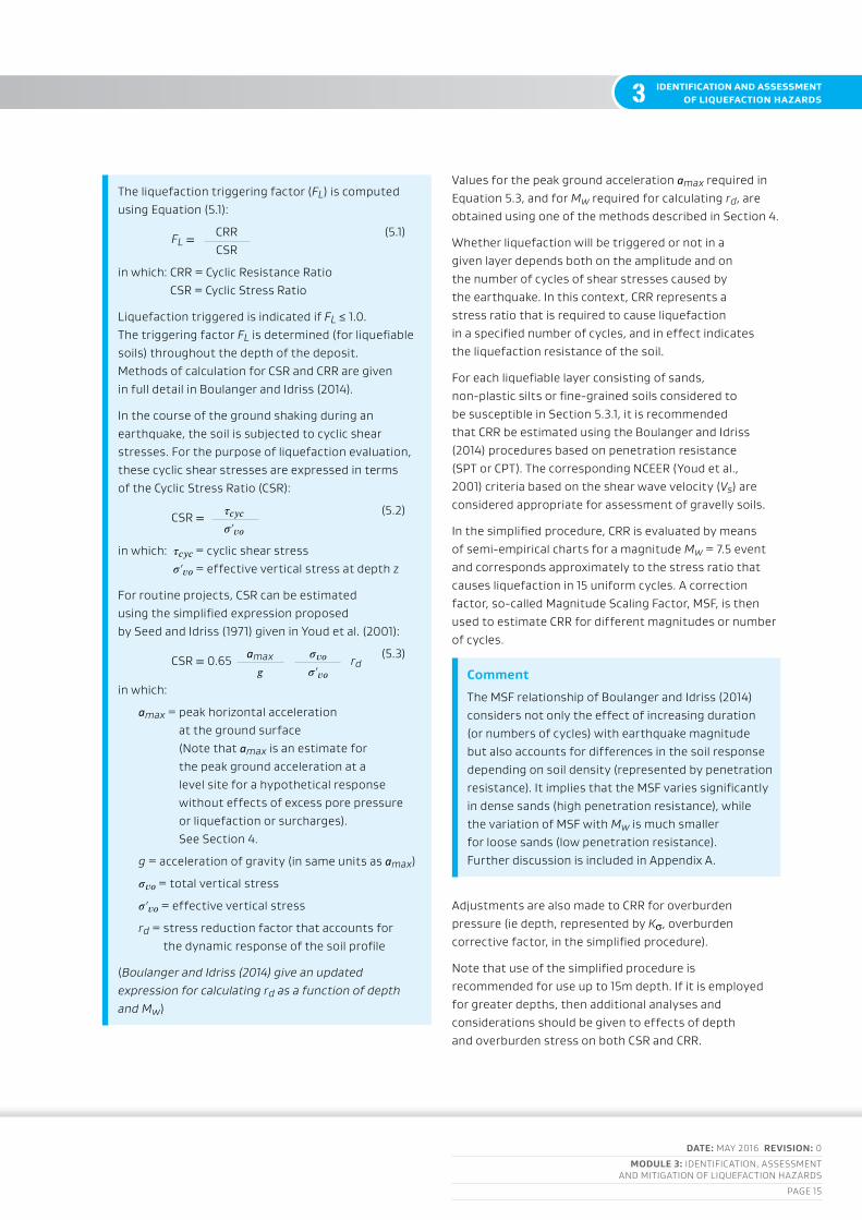
the liquefaction triggering factor (FL) is computed using Equation (5.1):
FL = crr (5.1) csr
in which: crr = cyclic resistance ratio csr = cyclic stress ratio
liquefaction triggered is indicated if FL ≤ 1.0. the triggering factor FL is determined (for liquefiable soils) throughout the depth of the deposit. Methods of calculation for csr and crr are given in full detail in boulanger and idriss (2014).
in the course of the ground shaking during an earthquake, the soil is subjected to cyclic shear stresses. for the purpose of liquefaction evaluation, these cyclic shear stresses are expressed in terms of the cyclic stress ratio (csr):
csr = 𝜏𝑐𝑦𝑐 (5.2) 𝜎′𝑣𝑜
in which: 𝜏𝑐𝑦𝑐 = cyclic shear stress 𝜎′𝑣𝑜 = effective vertical stress at depth z
for routine projects, csr can be estimated using the simplified expression proposed by seed and idriss (1971) given in youd et al. (2001):
csr = 0.65 amax 𝜎𝑣𝑜 rd (5.3)
𝑔 𝜎′𝑣𝑜in which:
amax = peak horizontal acceleration at the ground surface (note that amax is an estimate for the peak ground acceleration at a level site for a hypothetical response without effects of excess pore pressure or liquefaction or surcharges). see section 4.
g = acceleration of gravity (in same units as amax)
𝜎𝑣𝑜 = total vertical stress
𝜎′𝑣𝑜 = effective vertical stress
rd = stress reduction factor that accounts for the dynamic response of the soil profile
(Boulanger and Idriss (2014) give an updated expression for calculating rd as a function of depth and Mw)
Values for the peak ground acceleration amax required in Equation 5.3, and for Mw required for calculating rd, are obtained using one of the methods described in section 4.
Whether liquefaction will be triggered or not in a given layer depends both on the amplitude and on the number of cycles of shear stresses caused by the earthquake. in this context, crr represents a stress ratio that is required to cause liquefaction in a specified number of cycles, and in effect indicates the liquefaction resistance of the soil.
for each liquefiable layer consisting of sands, non-plastic silts or fine-grained soils considered to be susceptible in section 5.3.1, it is recommended that crr be estimated using the boulanger and idriss (2014) procedures based on penetration resistance (sPt or cPt). the corresponding ncEEr (youd et al., 2001) criteria based on the shear wave velocity (Vs) are considered appropriate for assessment of gravelly soils.
in the simplified procedure, crr is evaluated by means of semi-empirical charts for a magnitude Mw = 7.5 event and corresponds approximately to the stress ratio that causes liquefaction in 15 uniform cycles. a correction factor, so-called Magnitude scaling factor, Msf, is then used to estimate crr for different magnitudes or number of cycles.
Comment
the Msf relationship of boulanger and idriss (2014) considers not only the effect of increasing duration (or numbers of cycles) with earthquake magnitude but also accounts for differences in the soil response depending on soil density (represented by penetration resistance). it implies that the Msf varies significantly in dense sands (high penetration resistance), while the variation of Msf with Mw is much smaller for loose sands (low penetration resistance). further discussion is included in appendix a.
adjustments are also made to crr for overburden pressure (ie depth, represented by Ks, overburden corrective factor, in the simplified procedure).
note that use of the simplified procedure is recommended for use up to 15m depth. if it is employed for greater depths, then additional analyses and considerations should be given to effects of depth and overburden stress on both csr and crr.

DATE: May 2016 REvision: 0
MoDulE 3: idEntification, assEssMEnt and Mitigation of liquEfaction hazards
PagE 16
3identification and assessment of liquefaction hazards
Comment
in their recent revision of the cPt-based liquefaction triggering procedure, boulanger and idriss (2014) indicated that the database of cPt liquefaction case histories is limited to depths less than 12m with very few data points for depths greater than 9m. one should also acknowledge that in the simplified triggering procedure, liquefaction at various depths is considered by using a set of parameters incorporating the effects of depth on the seismic demand (stress reduction factor, rd), penetration resistance (normalizing factors CN or CQ) and liquefaction resistance (overburden stress factor, Kσ). there are significant uncertainties with these parameters for depths greater than those covered in the database. With this background in mind, application of simplified liquefaction evaluation procedures should be limited to 15m depth. Extrapolation to 20m depth should account for the increased uncertainties at depths greater than 15m by evaluating the effects of variation in parameters, over the relevant range of their values, through sensitivity studies.
importantly, empirically-based liquefaction triggering procedures divide case histories into two categories:
1 cases wherein surface manifestations of liquefaction were observed (ie liquefaction cases)
2 cases wherein surface manifestations of liquefaction were not observed (ie no liquefaction cases).
in the latter case, it is possible that liquefaction may have occurred deeper within the soil profile, but a non-liquefiable surface layer could have obscured its manifestation on the ground surface. thus, the simplified empirical method appears to be the most suitable for evaluating shallow liquefaction and for identifying those cases wherein surface manifestations of liquefaction are likely to occur.
special expertise and considerations are required for liquefaction evaluation at greater depths such as in the case of deep foundations, earth dams, tailing dams or thick reclaimed fills. in such evaluations, cyclic stress ratios (seismic demand) at depths greater than 20m should be evaluated using dynamic analyses, including considerations of uncertainties, and variations associated with the ground motion characteristics and dynamic ground response. Effects of large depths and high overburden stresses on the liquefaction resistance of soils should be carefully evaluated using experimental evidence from relevant soils. consequences of liquefaction should be considered in the context of the particular structure, including stability, deformation and interaction issues.
Values for crr correlated to cPt and sPt depend significantly on the fines content (fc) of the soil for two main reasons:
1 the presence of fines affects the resistance of soil to cyclic loading, and
2 the presence of fines also reduces the penetration resistance measured in the cPt and sPt.
accordingly, the determination of the fc of the subject soil is critically important to the liquefaction triggering analysis (and also to the determination of liquefaction susceptibility, as discussed in section 5.3.1). adjustments are made to increase the measured values of cPt (𝑞𝑐) and sPt (N) in silty sand to give ‘equivalent’ resistance values for clean sand using the procedure of boulanger and idriss (2014).
for the sPt, it is straightforward to recover the split-spoon samples and have the fc measured in a laboratory (and also the Pi for susceptibility determination). for the cPt, no sample is recovered and instead a correlation is made between fc and the soil behaviour type index Ic using the procedure given in boulanger and idriss (2014).
the correlation between fc and Ic is very weak, and for high risk/high consequence projects, cPt testing should be complemented by drilling and sampling of potentially problematic soils to verify the Ic correlations with fc or determine site specific correlations for each soil layer (or make fc corrections manually in the analysis). Where sampling and measurement of fc is not carried out, the sensitivity of the analysis to the fc – Ic correlation should be investigated by varying the correlation-fitting factor according to the recommendation of boulanger and idriss (2014).

DATE: May 2016 REvision: 0
MoDulE 3: idEntification, assEssMEnt and Mitigation of liquEfaction hazards
PagE 17
3 identification and assessment of liquefaction hazards
Comment
further discussion of the fc – Ic correlation is given in appendix a. boulanger and idriss (2014) recommend varying their correlation-fitting factor cfc over the range -0.29 to +0.29, about equivalent to +/- 1 standard deviation, to test the sensitivity of the analysis to variations in the fc correlation to Ic. Efforts to obtain site specific correlations for cfc should be carried out with care given the difficulties associated with obtaining representative soil samples from the exact locations of specific cPt readings. single point correlations for a site may be less reliable than the published correlation that is based on significant numbers of data points.
a probabilistic version of the cPt-based liquefaction triggering procedure is presented in boulanger and idriss (2014). the ‘normal’ deterministic, simplified procedure recommended in this guideline uses a semi-empirical curve for crr corresponding to a 16 percent probability (about 1 standard deviation) for liquefaction triggering at FL=1, considering uncertainty in the triggering analysis alone. the uncertainty in the liquefaction triggering analysis is much smaller than the uncertainty in the seismic hazard evaluation, and may often be smaller than the uncertainty in the site characterisation (boulanger and idriss, 2014).
for site assessments being carried out for purposes of compliance with the building code, it is recommended that this ‘normal’ probability of 16 percent be maintained in the liquefaction triggering analysis.
Procedures for gravelly soils based on large penetration tests (bPt) are discussed in youd et al. (2001). Effects of grain size distribution on penetration resistance are discussed in tokimatsu, (1988); Kokusho and yoshida (1997); and cubrinovski and ishihara (1999).
Comment
uniform gravels in which gravel-size particles form the soil matrix have lower liquefaction potential than sandy soils because of their high hydraulic conductivity and greater stiffness and strength. for these reasons, such gravels show greater resistance to cyclic loading including lower rate of excess pore pressure build-up, and smaller cyclic strains. Even when liquefied, such gravels would have a limited strain potential and would not manifest liquefaction instability typical for sandy soils. however, confined gravels and gravelly soils containing significant amount of sands and fines (well-graded gravels) should be considered of similar liquefaction susceptibility as sandy soils. Penetration tests in gravels should be carefully interpreted to account for the grain-size effects on the penetration resistance. in this context, shear wave velocity-based evaluation offers an alternative practical approach for assessment of gravels.

DATE: May 2016 REvision: 0
MoDulE 3: idEntification, assEssMEnt and Mitigation of liquEfaction hazards
PagE 18
3identification and assessment of liquefaction hazards
5.3 liquefaction-induced ground deformation
the significant reduction in stiffness and strength of soils from build-up of excess pore water pressure results in development of large shear strains in the ground during intense ground shaking. the peak cyclic (transient) shear strains typically range from two percent in dense sands to four percent in loose sands, resulting in large cyclic lateral displacements of the liquefied layer. in the 1995 Kobe earthquake the peak lateral displacements within liquefied fills were up to about 0.5m (ishihara and cubrinovski, 2005). these large cyclic lateral movements are important to consider because they may generate significant kinematic loads on buried structures and deep foundations.
Post-liquefaction behaviour is characterised by a complex process involving dissipation of excess pore water pressure, sedimentation, re-solidification, and re-consolidation of the liquefied soil eventually resulting in settlement of the ground. loss of soil volume due to sand ejecta on the ground surface can also significantly contribute to global and differential settlements. these liquefaction-induced settlements occur during and after the earthquake shaking, and can be significant even for free-field level-ground sites, ie without the presence of an overlying structure.
liquefaction-induced settlement should not be misinterpreted as densification of the ground or an indication of an increase in the liquefaction resistance of the liquefied soils. on the contrary, liquefaction
usually results in non-homogeneity, vent holes, weaknesses in the ground, and post-liquefaction soil fabric with low liquefaction resistance. during the canterbury earthquake sequence, many sites in christchurch repeatedly liquefied during strong earthquakes, often exhibiting more severe liquefaction effects in the subsequent events.
the magnitude of liquefaction-induced ground displacements is generally related to the liquefaction triggering factor FL and to the overall thickness of the liquefied layer (ishihara, 1985; ishihara and yoshimine, 1992). based on general interpretation of these relations, table 5.1 summarises performance levels for liquefied soil deposits, and should be used for general guidance only.

DATE: May 2016 REvision: 0
MoDulE 3: idEntification, assEssMEnt and Mitigation of liquEfaction hazards
PagE 19
3 identification and assessment of liquefaction hazards
Table 5.1: General performance levels for liquefied deposits
PERfoRMAnCE lEvEl
EffECTs fRoM ExCEss PoRE wATER PREssuRE AnD liquEfACTion
ChARACTERisTiCs of liquEfACTion AnD iTs ConsEquEnCEs
ChARACTERisTiC FL, lPi
l0 insignificantno significant excess pore water pressures (no liquefaction).
FL > 1.4 lPi=0
lsn <10
l1 Mildlimited excess pore water pressures; negligible deformation of the ground and small settlements.
FL > 1.2 lPi = 0
lsn = 5 – 15
l2 Moderate
liquefaction occurs in layers of limited thickness (small proportion of the deposit, say 10 percent or less) and lateral extent; ground deformation results relatively small in differential settlements.
FL ≈ 1.0 lPi < 5
lsn 10 – 25
l3 high
liquefaction occurs in significant portion of the deposit (say 30 percent to 50 percent) resulting in transient lateral displacements, moderate differential movements, and settlement of the ground in the order of 100mm to 200mm.
FL < 1.0 lPi = 5 – 15
lsn = 15 – 35
l4 severe
complete liquefaction develops in most of the deposit resulting in large lateral displacements of the ground, excessive differential settlements and total settlement of over 200mm.
FL << 1.0 lPi > 15
lsn > 30
l5 very severe
liquefaction resulting in lateral spreading (flow), large permanent lateral ground displacements and/or significant ground distortion (lateral strains/stretch, vertical offsets and angular distortion).
notes
1 liquefaction of relatively thin layers of near-surface soils could be very damaging, and may produce effects equivalent to Performance levels l3 and l4.
2 a relatively thin liquefied layer with low residual strength could be responsible for lateral spreading and consequent very severe effects (Performance level l5).
3 lPi (iwasaki et al., 1978) and lsn (van ballegooy et al., 2014) are damage indices that quantify liquefaction-induced damage by combining the effects of the severity of liquefaction (value of FL or fs), thickness of liquefied soils and their location within the soil profile. the threshold values for these indices shown in relation to the performance levels are only indicative values. these thresholds may vary and do not cover all liquefaction cases (scenarios and ground conditions). these indices are typically applied for area-based screening, and in such applications have reasonable predictive capacity, but may mispredict damage/performance for about 20 percent to 30 percent of the cases. Maurer et al. (2014) and van ballegooy et al. (2014) provide significant insights on liquefaction-induced land damage and its interpretation through land damage indices lPi and lsn.
4 all being equal (ie FL, thickness and location of liquefied layer), liquefaction consequences and magnitude of liquefaction-induced ground deformation strongly depend on the density of the soil. lsn quantifies this effect in a simplified manner. severity of liquefaction effects decreases with increasing density of the soils, and importantly the mechanism of ground deformation also changes as the density of the soil increases (eg flow liquefaction, zero-effective stress liquefaction, and nearly zero-effective stress transient liquefaction with cyclic mobility are characteristic types of behaviour associated with very loose, loose to medium dense, and dense sands respectively).
5 the lPi and lsn should be considered in the context of particular ground conditions and structure of interest. the ranges provided in the table are based on triggering calculations using boulanger and idriss (2014) method, and analyses and interpretation of liquefaction effects in the 2010–2011 canterbury earthquakes.

DATE: May 2016 REvision: 0
MoDulE 3: idEntification, assEssMEnt and Mitigation of liquEfaction hazards
PagE 20
3identification and assessment of liquefaction hazards
there are considerable uncertainties regarding the stiffness and strength of liquefying soils, and consequent ground deformation. the magnitude and spatial distribution of lateral spreading displacements are particularly difficult to predict. these uncertainties should be considered in the design.
it is prudent to assume that effects of liquefaction, including consequent ground deformation, can be highly non-uniform (horizontally and vertically) across short distances, and that differential movements, zones of weakness, and irregularity of ground distortion often occur.
for level ground sites, the severity of ground damage caused by liquefaction is affected by the properties and thickness of the liquefied layer, and by the location of the liquefied layer within the soil profile. ground displacements and liquefaction-induced damage generally increase with the thickness of the liquefied layer, and with the proximity of the liquefied layer to the ground surface and structure foundations. shallow liquefaction (associated with large volumes of sand ejecta and ground distortion) was particularly damaging to shallow foundations, roads and buried pipelines (water and wastewater) in the 2010 to 2011 christchurch earthquakes. surface manifestations of liquefaction (ground rupture and sand boils) are also influenced by the presence, thickness and quality (strength, continuity and integrity) of an overlying non-liquefied crust at the ground surface.
the presence of non-liquefiable crust at the ground surface may reduce the manifestation and damaging effects of liquefaction, as observed by ishihara (1985) and more recently in the canterbury earthquake sequence (tonkin and taylor, 2014). such beneficial effects of the crust should only be expected in cases where lateral spreading does not occur, and where the crust is sufficiently thick and robust to ensure reduced differential movements for relatively light structures on shallow foundations.
the effects of the crust layer should be considered in conjunction with the response of the whole deposit, and in particular the liquefying layer beneath the crust. the effects of soil-structure interaction need to be considered, including loads from the crust on the structure. in this context, effects of the crust layer are not always beneficial, and there are numerous cases in which large lateral loads are applied from the crust on foundations, buried structures and piles during ground shaking, and especially with lateral spreading.
there is evidence from the canterbury earthquake sequence that an adequate non-liquefied crust at the ground surface, and highly inter-layered silty soils in the top 5 to 6m (consisting of layers of sandy soils and silty soils of higher Ic values), reduced or suppressed the effects of liquefaction and its manifestation on the ground surface.
if at any depth of the investigated deposit the liquefaction triggering factor is FL ≤ 1.1, then liquefaction-induced ground deformation and effects of liquefaction on structures should be evaluated.
the magnitude and extent of ground deformation depend on various factors, including initial density of the soil, thickness and location of the liquefied layer, intensity of ground shaking, presence of driving stresses under gravity loads, and drainage conditions. if triggering of liquefaction is predicted (FL ≤ 1.0), then both lateral displacement and settlement of the ground need to be estimated. some procedures for estimating liquefaction-induced ground deformation are discussed below.

DATE: May 2016 REvision: 0
MoDulE 3: idEntification, assEssMEnt and Mitigation of liquEfaction hazards
PagE 21
3 identification and assessment of liquefaction hazards
Comments on ishihara criteria for damaging liquefaction based on crust thickness
ishihara (1985) developed criteria identifying conditions for occurrence of liquefaction-induced damage based on the thickness of a crust of non-liquefied soils at the ground surface (H1), and thickness of the underlying liquefied sand layer (H2). these criteria are expressed in a H2 – H1 chart in which boundary curves for identification of liquefaction-induced damage are shown for three levels of accelerations (0.2g, 0.3g, and 0.4–0.5g). because the chart is often used in liquefaction evaluation in practice, it is useful to briefly describe its features and limitations.
the chart was developed based on observations from two earthquakes:
• 1983 nihonkai-chubu earthquake (Japan; M=7.7), and
• 1976 tengshan earthquake (china; M=7.8).
in the absence of ground motion records, ishihara estimated accelerations of 0.2g for the nihonkai-chubu earthquake and 0.4–0.5g for the tengshan earthqauke respectively. hence, the two solid lines in the original chart of ishihara (1985), for 0.2g and 0.4–0.5g, relate directly to the nihonkai-chubu and tengshan earthquake case histories, respectively. the dashed line for 0.3g in the original chart was
obtained by a simple interpolation and without direct evidence. in summary, on the seismic demand (earthquake loading) side, the chart summarises interpretation for M=7.7–7.8 earthquakes, and includes rough approximation of associated values of amax.
another important feature that needs to be acknowledged is that, in the development of the chart, ishihara considered a relatively simple soil profile of uniform sand deposit with a mantle of non-liquefiable layer or crust at the ground surface. Experiences from the christchurch earthquakes have shown that other factors such as presence of fines or silty soils, of low plasticity, and highly stratified soils of different liquefaction potential, including non-liquefiable soils, may substantially affect the liquefaction manifestation and associated land damage. in this context, the ishihara chart should not be seen as a generalised criterion that is applicable over a wide range of subsurface conditions. in summary, the ishihara criteria were developed based on limited data, and involved multiple simplifying assumptions to arrive at conceptual criteria for general guidance. they were not intended to set or be used as a standard. this intent should be reflected in engineering evaluations referring to this chart.
5.3.1 liquefaction-induced settlementsseveral simplified methods are available for calculation of liquefaction-induced settlements of free-field level-ground sites, eg tokimatsu and seed (1987), ishihara and yoshimine (1992), and zhang et al. (2002). these methods are compatible with the simplified procedure for assessment of liquefaction triggering described in these guidelines. the calculation of liquefaction-induced settlements is based on estimation of cumulative vertical strains due to reconsolidation of liquefied soils, which typically range from one percent for dense sands to five percent for loose sands. hence, thick deposits of poorly compacted sandy soils have especially high potential for large settlements.
additional settlements may be caused by shear stresses induced by overlying structures and also by displacement of foundation soils, including loss of soil volume due to sediment ejecta. When pronounced, such mechanisms produce excessive differential settlements. areas affected by lateral spreading also
commonly exhibit non-uniform settlements due to slumping of soils associated with the complex lateral expansion of the soil masses towards the waterway. none of these settlement-producing mechanisms is accounted for in the above simplified methods for evaluation of liquefaction-induced settlement.
in view of the limitations of the existing simplified methods (which only allow for post-liquefaction reconsolidation settlements in level ground free-field deposits), and particularly the pronounced non-uniformity of liquefaction effects and consequent ground deformation, it is rational to consider the calculated settlements based on the simplified methods only as a proxy for the damaging effects of liquefaction rather than a reliable estimate of ground settlement. Moreover, the difference between the post-liquefaction reconsolidation settlements calculated at one site investigation point and at another site investigation point should not be interpreted as representing the likely differential settlement between the two points.
DATE: May 2016 REvision: 0
MoDulE 3: idEntification, assEssMEnt and Mitigation of liquEfaction hazards
PagE 22
3identification and assessment of liquefaction hazards
5.3.2 Cyclic (transient) ground displacementsthe empirical procedure proposed by tokimatsu and asaka (1998) can be used for a preliminary assessment of cyclic ground displacements in liquefied soils of level-ground sites. the procedure is based on an empirical chart correlating the maximum cyclic shear strain in liquefied soil with the sPt blow count and csr. cyclic ground displacements can be calculated by a bottom-up integration of the estimated cyclic shear strains throughout the depth of the deposit.
5.3.3 Permanent lateral spreading displacements
Permanent lateral spreading displacements occur in sloping ground and are especially prevalent near to free faces such as waterways.
Empirical charts
there are several empirical methods available for evaluation of lateral spreading displacements (youd et al., 2002; tokimatsu and asaka, 1998; zhang et al., 2004). using field observations from case histories of lateral spreads caused by liquefaction in past earthquakes, youd et al. (2002) developed equations for prediction of lateral ground displacements due to spreading using regression techniques with compiled data from case histories. factors such as site configuration, sPt resistance, earthquake magnitude, and site-to-source distance are accounted for in this procedure.
the accuracy of the simplified empirical methods for lateral spreading displacements is relatively low, and the predicted ground displacements are generally within a factor of two (ie half or twice) of the observed lateral spreading displacements though even larger deviations between predicted and observed displacements are often encountered. the low level of accuracy in the predictions, lack of theoretical basis of the empirical methods, and the complexity of lateral spreading emphasize the need to consider and account for uncertainties in the estimates of lateral spreading displacements in engineering evaluations.
Comment
Estimates of lateral spreading should consider several of the available methods and so consider the range and variability of the predictions and possible extent of the hazard. cubrinovski and robinson (2015) provide guidance for a more systematic evaluation of lateral spreading based on a comprehensive study of lateral spreads observed in the 2010–2011 christchurch earthquakes.
newmark (rigid-block) method
Earthquake-induced permanent lateral displacements can be estimated using newmark’s procedure for displacement of a rigid body subjected to base accelerations (newmark, 1965). in this method, yield acceleration is calculated using the limit equilibrium approach, and movement of the slope (earth structure) is then calculated either by using acceleration time history records and integrating episodes when the ground acceleration exceeds the yield level, or by using approximate equations developed from analyses based on a suite of earthquake records (eg bray and travasarou, 2007). in the calculations, it is important to consider the uncertainties in the estimates of the yield acceleration and residual strength of liquefying or liquefied soils. additional information is given by bray and travasarou (2007), Jibson (2007), and olson and Johnson (2008).
it is important to acknowledge that the underlying assumption for rigid-body behaviour of the newmark method is incompatible with the flexible deformation mode of liquefiable soils. this limitation should be considered when evaluating the applicability of the method to a particular problem. the method may still be useful for cases with isolated pockets of liquefiable soils, and provides a rational approach for quantifying the beneficial effects of deck strutting resulting in reduction of lateral spreading displacements at bridge abutments (PEEr, 2011).
DATE: May 2016 REvision: 0
MoDulE 3: idEntification, assEssMEnt and Mitigation of liquEfaction hazards
PagE 23
3 identification and assessment of liquefaction hazards
5.4 residual strength of liquefied soils
residual shear strength of liquefied soils can be used in the assessment of post-liquefaction stability of sloping ground, risk of bearing failures, and liquefaction-induced lateral displacements. Experience from previous earthquakes and experimental studies on scaled-down models indicate that residual strength of liquefied soils can be much lower than the undrained strength of soils. a nearly complete loss of effective stress, which is sustained during the pore water pressure redistribution and groundwater flow, and potential loosening of liquefied soils (void ratio redistribution and expansion) due to upward water flow are considered the primary reasons for the low residual strength of liquefied soils. in cases where a low permeability layer acts as a barrier and prevents the upward flow, significant loosening of the liquefied layer may occur at this interface (eg water film effects and void redistribution, Kokusho, (2003)).
there are several empirical relationships currently available for estimating the residual shear strength of liquefied soils:
• the empirical correlation of seed and harder (1990) presents the residual strength Sr as a function of the equivalent sand sPt blow count, (N1)60cs-Sr (note that the fines content correction for sPt blow count for estimating residual strength differs from the fines-content correction used in the liquefaction triggering evaluation).
• olson and stark (2002) provide empirical correlations both based on normalized sPt blow count (N1)60 and normalized cPt resistance 𝑞𝑐1n. in both cases, the residual strength is defined in terms of a ratio (Sr/𝜎′𝑣𝑜) or normalized strength.
• idriss and boulanger (2008) recommend relationships in terms of Sr/𝜎′𝑣𝑜 based on both (N1)60cs-Sr and (𝑞𝑐1n)cs-Sr for two separate conditions:
a Where void ratio redistribution effects are expected to be negligible (this case should not be used unless it can be shown that void redistribution is not possible).
b Where void ratio redistribution effects could be significant.
notethese relationships have been extrapolated beyond the range of available data (eg the relationships are shown with dashed lines for 𝑞𝑐iNcs > 90 in idriss and boulanger, (2008)) indicating uncertainties and lack of evidence over the extrapolated range. the absence of case histories where 𝑞𝑐iNcs > 90 or (N1)60cs-Sr > 15 (ie denser soils) supports the concept that it is loose soil deposits which are the primary candidates for liquefaction induced instability, but this does not eliminate the possibility that denser soils within the extrapolated range are immune from liquefaction-induced flow failures. generally, dense soils may liquefy, but they are more likely to undergo cyclic mobility with limited strain potential rather than flow failures.
it is important to note that the above-mentioned relationships are based on similar data sets and they differ essentially in the interpretation of observations of the case histories. at a specialised session on residual strength (gEEsdiV conference, sacramento, May 2008) there was general consensus that, for the time being, both normalised and non-normalised relationships should be used in parallel. it has been suggested that the normalised form of the residual strength (ie Sr/𝜎′𝑣𝑜) better reflects the potential strength loss due to void redistribution (idriss and boulanger, 2008) and the effects of depth of liquefaction (location of the liquefied layer within the profile) or effective overburden stress. in view of the uncertainties involved, it seems prudent to evaluate the sensitivity of the results to assumed Sr values, and account for the outcome of such sensitivity study in the interpretation of the results and decision-making.

DATE: May 2016 REvision: 0
MoDulE 3: idEntification, assEssMEnt and Mitigation of liquEfaction hazards
PagE 24
3identification and assessment of liquefaction hazards
5.5 Effects of liquefaction on structures
there are numerous case histories from past earthquakes demonstrating the significant effects of soil liquefaction on the seismic performance of engineering structures (buildings, bridges, storage tanks, port structures, embankments, levees/stopbanks, and lifelines). the canterbury earthquake sequence provided many well-documented case histories on the performance of buildings and infrastructure in a new zealand natural and built environment. if triggering of liquefaction is predicted and the resulting ground displacements are large, then effects of liquefaction on structures should be assessed and addressed in the design.
While detailed assessment of effects of liquefaction on structures is beyond the scope of these guidelines, some important issues for consideration in the design of structures at liquefiable sites are briefly discussed below:
• liquefaction-induced settlements due to re-consolidation of liquefied soils occur in level ground sites irrespective of whether or not there is an overlying structure. When structures are founded over or within liquefied soils, additional settlements will occur due to shearing stresses induced by the overlying structure, and also because of displacement and loss of soils beneath foundations due to liquefaction-induced sediment ejecta (cubrinovski et al., 2011; bray et al., 2014; bray and dashti, 2014). these additional settlements can be of similar magnitude or even greater than the re-consolidation settlements, and can be particularly large in the case of heavy structures or where there is considerable sediment ejecta. there are no widely accepted simplified procedures for prediction of structure-induced settlements. Prediction of differential, settlements in liquefied soils is particularly difficult and therefore these settlements are typically assumed to be proportional to the total settlement (Martin et. al., 1999). While shear-induced settlement due to rocking and ratcheting effects occur during the vibration of the superstructure, a substantial portion of liquefaction-induced differential settlements may develop after strong shaking and the relative timing should be accounted for when evaluating the capacity of the structure to accommodate such settlements.
• large lateral movements from ground oscillation, and lateral spreading of liquefied soils in particular, are damaging for pile foundations (cubrinovski et al., 2014). large passive soil pressures from a non-liquefied crust layer and effects from kinematic loads due to ground movement and inertial loads due to vibration of the superstructure, need to be considered in the assessment of pile foundations. Maximum inertial and kinematic loads may or may not occur concurrently depending upon characteristics of the ground motion, dynamic characteristics of the site and soil-structure system, development of pore pressures and soil-pile-structure interaction (boulanger et al., 2007; tokimatsu et al., 2005). Various methods for analysis of piles in liquefying soils are available based on the pseudo-static approach (eg ashford et al., 2011; cubrinovski et al., 2009). care must be taken to account for uncertainties in loads and properties of liquefied soils when using these simplified methods. Module 4 of the guidelines provides more information.
• lateral spreading displacements can be very large and highly variable in waterfront areas (the magnitude of these displacements changes rapidly with the distance from the waterfront). hence, structures founded close to quay walls and revetment lines may be subjected to differential lateral displacements that may stretch the foundation and adversely affect the structure. interpretation and classification of lateral spreads observed in the christchurch earthquakes and guidance for evaluation of lateral spreading are provided in cubrinovski and robinson (2015). Effects of lateral spreading on bridges including development of a specific mechanism for short-span bridges are summarized in cubrinovski et al. (2014).

DATE: May 2016 REvision: 0
MoDulE 3: idEntification, assEssMEnt and Mitigation of liquEfaction hazards
PagE 25
3 identification and assessment of liquefaction hazards
• liquefaction may cause bearing failures and lead to overall instability with tilting and overturning of structures on poorly designed foundations. Potential punching failures through a surface crust and reduction of the foundation bearing capacity should be considered in the design. liquefaction in the immediate foundation soils or their vicinity would usually result in excessive transient and permanent displacements/settlements and potential damage to the foundations that could propagate to the superstructure (cubrinovski and Mccahon, 2011; cubrinovski et al., 2011; bray et al., 2014; bray and dashti, 2014).
• significant vertical and horizontal ground displacements should be accommodated in the design of foundations and structures in liquefiable soils. if the structure and foundation cannot tolerate the imposed ground displacements, then additional measures such as strengthening of the foundation, ground improvement or structural modification should be implemented. both the serviceability limit state (sls) and the ultimate limit state (uls) need to be considered separately in the assessment of liquefaction unless the risk of liquefaction or ground damage occurring for the sls is acceptably low (FL ≥ 1.2).
• liquefied soils behave as a heavy liquid causing relatively light structures such as buried pipelines, manholes, pump wells and basements to ‘float’ to the ground surface. buried lifelines are also subjected to differential movements caused by spatial variability of ground conditions and ground displacements. seepage action, redistribution of excess pore water pressures and rise of the phreatic surface may trigger post-earthquake failures in dams and embankments (ishihara, 1985).
inertial loads due to strong shaking (vibration of the superstructure) are significant during the cyclic phase (ie during strong ground shaking and development of excess pore water pressures) but may decrease substantially after triggering of liquefaction because of the reduced capacity of liquefied soils to transfer shear stresses. such reduction in acceleration amplitudes post-liquefaction may be pronounced in loose sandy soils that exhibit contractive behaviour, but may be negligible or even reversed in dense soils exhibiting acceleration spikes from cyclic mobility associated with temporary dilation during cyclic shearing. the substantial reduction in stiffness of liquefied soils leads to elongation of the vibration period of the deposit which in turn may cause amplification of the response of long-period structures (systems).
When evaluating the effects of liquefaction and lateral spreading on pile foundations using simplified analysis it is important to adopt a consistent scenario with compatible values for the magnitude of ground displacements, soil stiffness and strength properties, and inertial loads from the building. significant lateral spreading is associated with loose soils and there will likely be a substantial decrease in inertial loads after liquefaction triggering, as well as marked reduction in strength and stiffness of the liquefied soil. Very large ground displacements (indicating low stiffness and strength of liquefied soils) are incompatible with high accelerations or inertial loads which are associated with relatively high stiffness and dilation during cyclic mobility or pre-liquefaction soil stiffness. More detailed guidance on the treatment of kinematic and inertial loads in simplified pseudo-static analyses of piles in liquefying soils are given in Module 4.
DATE: May 2016 REvision: 0
MoDulE 3: idEntification, assEssMEnt and Mitigation of liquEfaction hazards
PagE 26
3identification and assessment of liquefaction hazards
5.6 advanced numerical procedures
advanced numerical procedures may be appropriate for significant projects or may be justified where there are uncertainties about the likelihood of liquefaction or where the consequences of liquefaction may be significant. advanced analyses based on the effective stress principle are particularly valuable in the evaluation of the effectiveness of ground improvement and structural strengthening measures for mitigation of liquefaction.
advanced numerical procedures for liquefaction assessment include total stress and effective stress dynamic analyses. the latter is specifically tailored to analysis of soil deposits, stability of embankments, and soil-structure systems affected by excess pore water pressures and liquefaction, and is the primary tool for detailed assessment of liquefaction and its effects on structures. the effective stress analysis addresses triggering of liquefaction, consequent ground deformation, and effects of liquefaction on structures in an integrated manner, and therefore can provide a more realistic simulation of the complex ground response and soil-structure interaction in liquefying soils, though some limitations must be recognized as discussed below.
first, some advantages of this analysis procedure are listed below:
• the analysis allows detailed simulation of the liquefaction process including build-up of excess pore water pressure, triggering of liquefaction, subsequent losses in strength and stiffness, and post-shaking dissipation of excess pore pressure. it provides realistic simulation of earthquake loads throughout the depth of the foundation soil by considering responses of individual layers and cross interaction amongst them (base-isolation effects and progressive seepage-induced liquefaction due to upward flow of water).
• spatial and temporal variation of ground deformation develops in accordance with changes in stiffness and earthquake loads. thus, both inertial loads due to vibration of the structure and kinematic loads due to ground movements are concurrently considered while accounting for soil nonlinearity and effects of excess pore water pressure on soil behaviour.
• Effects of soil-structure interaction are included in the analysis, in which sophisticated non-linear models can be used both for soils and structural members.
• the analysis allows assessment of the effectiveness of countermeasures against liquefaction (ground improvement or structural modification),including their effects on ground deformation and eismic performance of structures.
Practical disadvantages of the effective stress analysis are that it requires:
• selection of appropriate earthquake records to be used as input motion in the analysis by considering the seismic hazard for the site.
• high-quality and specific data on the in situ conditions, physical properties and mechanical behaviour of soils (field investigations and specific laboratory tests on soil samples), particularly if the analysis is used for quantifying the seismic performance of important structures.
• high demands on the user with respect to knowledge and understanding of the phenomena considered and particular features of the adopted numerical procedures.
all analysis methods and constitutive models have limitations with regard to their capability to model certain aspects of soils’ behaviour and simulate complex liquefaction phenomena. Particularly difficult to address are large strain/displacement problems, discontinuities, loss of soil volume due to ejecta, 3-d effects, and similar complex issues. a rigorous application of the advanced analyses, while acknowledging the limitations of the numerical procedures, is critically important for a high-quality assessment using numerical analyses (cubrinovski, 2011).
the total stress analysis is an alternative procedure for assessment of the seismic response of ground and soil-foundation-structure systems. this analysis, however, does not directly include effects of excess pore water pressures, and hence requires additional interpretation of non-linear soil behaviour and its simplification for modelling.

DATE: May 2016 REvision: 0
MoDulE 3: idEntification, assEssMEnt and Mitigation of liquEfaction hazards
PagE 27
3 mitigation of liquefaction and lateral spreading
6 mitigation of liquefaCtion and lateral sPreading
liquefaction-induced ground displacements may be large and often intolerable for the built environment.
ground deformation hazard arising from earthquake shaking (including liquefaction and lateral spreading) should be considered:
1 Where failure or excessive deformation of the ground might contribute to loss of life or loss of amenity of a building of importance level 2 or higher (refer nzs 1170.0 for definition of importance level)
2 Where failure or excessive deformation of the ground is a risk to services to or access to buildings of importance level 3 or higher.
two approaches are generally used to mitigate liquefaction and its consequences:
• soil remediation
• structural modification.
DATE: May 2016 REvision: 0
MoDulE 3: idEntification, assEssMEnt and Mitigation of liquEfaction hazards
PagE 28
3mitigation of liquefaction and lateral spreading
6.1 soil remediation
soil remediation methods effectively reduce ground deformation and effects of liquefaction either by preventing, limiting, or slowing-down the development of excess pore water pressure or by limiting the development of shear strains and vertical strains in the ground. soil remediation is commonly based on one or a combination of the following:
• densification (compaction, vibro-flotation, compaction piles, preloading) to increase liquefaction resistance (crr) and reduce deformability of the soil through increased strength and stiffness.
• solidification (deep mixing, permeation grouting) through cementation of soils.
• containment of liquefied soils and limitation of ground deformation by reinforcement and soil mixing walls.
• drainage (prefabricated drains, stone columns) for increased permeability and faster dissipation of excess pore water pressures.
details on mitigation measures, implementation, and assessment of their effectiveness may be found in Jgs (1997), seismic design guidelines for Port structures (ina, 2001), Martin et al. (1999) and Mitchell et al. (1998). advanced analysis procedures, and the effective stress analysis in particular, can be used for assessment of effectiveness of countermeasures against liquefaction.
following the canterbury earthquake sequence, comprehensive field trials were conducted by Eqc to investigate the effectiveness of various liquefaction-mitigation measures specifically for residential buildings and properties (tonkin & taylor, 2015).
these benchmark field tests indicate that:
1 the effectiveness of many techniques depends on the soil type and ground conditions (eg density, fines content and plasticity of fines, saturation, horizontal and vertical confinement);
2 some ground treatment procedures used in an inappropriate setting may produce highly non-uniform ground conditions and create weak zones with high potential for liquefaction;
3 details of ground improvement procedures and their implementation in the field are critically important, hence, calibration, validation and qa are essential aspects of ground improvement; and
4 ground improvement should be considered in the context of the particular structure and its characteristics, ground conditions and performance objectives; this evaluation should also consider a potential increase in the dynamic loads and response during shaking as a consequence of ground improvement.
More detailed guidance on ground improvement is provided in Modules 5 and 5a of the guidelines.
6.2 structural modification
Potential effects of liquefaction can be taken into account and accommodated in the design of the structure to reduce differential settlements and lateral movement within the foundation. this is commonly achieved by using stiff raft, rigid foundation beams/walls or deep pile foundations with sufficient lateral capacity to resist both inertial loads due to vibration of the superstructure, and kinematic loads due to ground movement. reduction of differential settlements and lateral deformation can also be achieved through structural modification that provides control of the damage of structural systems and load distribution to the foundations. some structure-specific examples of structural modification specific to liquefaction is given in the MbiE guidelines for residential buildings (MbiE, 2013) and light industrial buildings (MbiE, 2014).
More detailed guidance on foundation design is provided in Module 4 of the guidelines.

DATE: May 2016 REvision: 0
MoDulE 3: idEntification, assEssMEnt and Mitigation of liquEfaction hazards
PagE 29
3 clay soils
7 Clay soils
7.1 ground failure of clay soils
clay soils may significantly soften and fail under cyclic loading but do not exhibit typical liquefaction features and are therefore considered non-liquefiable. assessment of the cyclic strength (‘cyclic softening’) of ‘clay-like’ soils is quite different to the liquefaction assessment of ‘sand-like’ soils. cyclic strength can be assessed by either:
1 cyclic laboratory testing of ‘undisturbed’ soil samples, or,
2 Measuring the monotonic undrained shear strength using standard procedures (in situ, eg field vane, or cPt or laboratory, eg cu triaxial or simple shear test) and then applying an empirical correction factor.
boulanger and idriss (2006, 2007) proposed a procedure for evaluation of cyclic softening in ‘clay-like’ fine-grained soils during earthquakes. the procedure follows a format similar to that used in the simplified procedure for ‘sand-like’ soils and allows estimating the factor of safety against cyclic failure in ‘clay-like’ fine-grained soils (using a failure criterion of three percent peak shear strain). several approaches are provided for estimating the cyclic resistance ratio (crr) based on the undrained shear strength.
chen et al. (2006) provide recommendations regarding correction factors to adjust the static undrained shear strength of a clay soil to represent its peak dynamic strength. loading rate effects increase the peak dynamic undrained shear strength of clays relative to static strength whereas cyclic degradation effects reduce it. Progressive failure effects also influence the value of peak dynamic undrained shear strength that should be used in limit-equilibrium analyses. importantly, the potential for a post-peak drop in strength should be evaluated for sensitive clay soils, and the shear strength used in the analyses must be compatible with the calculated level of deformation.
Pending further research in this area, designers should make assessments of stability and deformation using the above procedures.
7.2 Mitigation of clay soils
the possibility of damaging ground deformations in ‘clay-like’ soils should be evaluated, including the effects on foundation capacity and overall stability of a building. options for mitigating clay soils are more limited than for granular soils and may include pre-loading with or without additional drainage. the typical approach to mitigation will often be structural modification, including the use of deep foundations or stiff raft foundations, or ground improvement by soil cement walls, for example.

DATE: May 2016 REvision: 0
MoDulE 3: idEntification, assEssMEnt and Mitigation of liquEfaction hazards
PagE 30
3volcanic soils
8 VolCaniC soilsMany volcanic soils have different properties to the more common sedimentary soils that comprise the majority of the case histories and research studies of liquefaction. the lack of studies on liquefaction in volcanic soils limits the availability of data to enable specific recommendations. however, the following properties are likely to influence the potential for liquefaction and consequential effects.
Volcanic soils include the following:
• airfall and pyroclastic flow deposits including ash, tuff, scoria, and ignimbrite soils
• residual soils and completely weathered volcanic rocks
• transported materials, including alluvium and lahar deposits
• other interbedded soils including paleosoils, loess, colluvium and diatomaceous silt.
ignimbrite soils are typically pumice dominant granular soils and are common in the bay of Plenty/central north island area. these can be locally homogeneous and thick, however, they are often interbedded with ash (eg ashfall between flow events) and paleosoils. these soils often have very high shear strength and very low density. note that the term pumice refers to highly vesicular, very angular particles typically from rhyolitic eruptions. Purmiceous should be used to described the material rather than the soil, as the material may be in situ (ignimbrite soil) or alluvial or airfall. these soils are difficult to investigate (eg sPt and cPt testing methods can be unreliable), however, it may be possible to reconstitute samples in triaxial cells or shear boxes, or recover ‘undisturbed’ samples. While these samples will be somewhat disturbed, test results may provide reference data for geotechnical evaluation and design. there are few studies and case histories regarding the liquefaction potential of ignimbrite soils.
alluvial soil with a high proportion of pumice material can also have very low density and relatively higher strength compared to more common sedimentary soils. these soils are typically finer than the ignimbrite soils and are often interbedded with other materials.
Pumiceous soil particles can be relatively weak compared to quartz and other more common sand minerals. shear failure can be by particle crushing rather than dilation (ie the failure can develop through the particles rather than around them). this is a fundamentally different failure mechanism to most soils because particle crushing in pumiceous soils may occur at lower levels of stresses that might be encountered in many geotechnical problems.
Volcanic ash refers to fine grained volcanic soils. these include airfall deposits, sometimes reworked by climate and weathering effects. the properties of ash can vary widely and many deposits are heterogeneous. ash can be sensitive and may have a distinct yield point (which can be related to stress or strain). the methods of assessing granular or cohesive behaviour using the plasticity index are useful, however, the behaviour of ash soils can change significantly when subject to large strains. Penetration testing methods (eg sPt and cPt) are reliable for ignimbrite soils; however, caution is required with assumptions of density and specific gravity. if undisturbed samples can be taken, then cyclic loading in triaxial cells or cyclic simple shear can provide useful results.
all of the above, as well as previous studies on liquefaction resistance of calcareous sands, suggest that conventional liquefaction evaluation procedures based on empirical charts for sedimentary soils of common sand minerals cannot be applied to volcanic soils, and that special considerations and assessment is required for such cases. laboratory testing of undisturbed or even reconstituted soil samples may provide basis for quantifying the liquefaction resistance and developing experimental evidence for establishment of liquefaction criteria for such soils.

DATE: May 2016 REvision: 0
MoDulE 3: idEntification, assEssMEnt and Mitigation of liquEfaction hazards
PagE 31
3 references
9 referenCes
beyzaei, c., bray, J., cubrinovski, M., riemer M., stringer M., Jacka M., and Wentz r. (2015). ‘liquefaction resistance of silty soils at the riccarton road site, christchurch new zealand,’ Proc. 6th Int. Conf. on Geotechnical Earthquake Engineering, 1–4 november 2015, christchurch.
boulanger r.W. and idriss, i.M. (2014). ‘cPt and sPt based liquefaction triggering Procedures,’ Report No. UCD/CMG–14/01, dept. of civil & Environmental Engineering, university of california at davis.
boulanger r.W. and idriss, i.M. (2004). ‘Evaluation of Potential for liquefaction or cyclic failure of silts and clays,’ Report No. UCD/CMG–04/01, dept. of civil & Environmental Engineering, university of california at davis.
boulanger r.W. and idriss, i.M. (2006). ‘liquefaction susceptibility criteria for silts and clays,’ Journal of Geotechnical and Geoenvironmental Engineering, 132 (11), 1413–1426pp.
boulanger r.W. and idriss, i.M. (2007). ‘Evaluation of cyclic softening in silts and clays,’ Journal of Geotechnical and Geoenvironmental Engineering, 133 (6), 641–652pp.
boulanger, r. chang, d., brandenberg, s. & armstrong, r. (2007). ‘seismic design of Pile foundations for liquefaction Effects,’ 4th Int. Conference on Earthquake Geotechnical Engineering-Invited Lectures, Ed. Pitilakis, 277–302pp.
bray, J.d. and sancio, r.b. (2006). ‘assessment of the liquefaction susceptibility of fine-grained soils,’ Journal of Geotechnical and Geoenvironmental Engineering, 132 (9), 1165–1177.
bray, J.d. and travasarou, t. (2007). ‘simplified Procedure for Estimating Earthquake-induced deviatoric slope displacements,’ Journal of Geotechnical and Geoenvironmental Engineering, ascE, 133(4), 381–392pp.
bray, J. d., and dashti, s. (2014). ‘liquefaction induced building Movement,’ Bulletin of Earthquake Engineering, Springer, 12(3), 1129–1156pp.
bray, J.d., cubrinovski, M., zupan, J. and taylor, M. (2014). ‘liquefaction Effects on buildings in the central business district of christchurch,’ Earthquake Spectra (special issue on the 2010–2011 canterbury Earthquakes), 30, (1), 85–109pp.
chen, W.y., bray, J.d., and seed, r.b. (2006) ‘shaking table Model Experiments to assess seismic slope deformation analysis Procedures,’ Proc. 8th US Nat. Conf. EQ Engrg., 100th Anniversary Earthquake Conference Commemorating the 1906 San Francisco Earthquake, EEri, april, Paper 1322.
cubrinovski, M. and ishihara, K. (1999). ‘Empirical correlation between sPt n-value and relative density for sandy soils,’ Soils and Foundations, 39 (5), 61–71pp.
cubrinovski, M., ishihara, K. and Poulos, h. (2009). ‘Pseudo-static analysis of Piles subjected to lateral spreading,’ Bulletin of the NZ Society for Earthquake Engineering 42(1): 28–38pp.
cubrinovski, M., rees, s. and bowman, E. (2010). ‘Effects of non-plastic fines on liquefaction resistance of sandy soils.’ in M. garevski and a. ansal (Ed.), Earthquake Engineering in Europe. Geotechnical, Geological, and Earthquake Engineering 17. (125–144). london & new york: springer.
cubrinovski, M. and Mccahon, i. (2011). ‘foundations on deep alluvial soils,’ technical report prepared for the canterbury Earthquakes royal commission.
cubrinovski, M. (2011). ‘seismic Effective stress analysis: Modelling and application.’ theme lecture, Proc. 5th Int. Conf. Earthquake Geotechnical Engineering, santiago, chile, 1–24.
cubrinovski, M., bray, J.d., taylor, M., giorgini, s., bradley b.a., Wotherspoon, l., and zupan, J. (2011). ‘soil liquefaction Effects in the central business district during the february 2011 christchurch Earthquake,’ Seismological Research Letters, 82, 893–904.
cubrinovski, M., haskell, J., Winkley, a., robinson, K. and Wotherspoon, l. (2014). ‘Performance of bridges in liquefied deposits during the 2010–2011 christchurch (new zealand) Earthquakes,’ ASCE Journal of Performance of Constructed Facilities 28(1): 24–39pp.
DATE: May 2016 REvision: 0
MoDulE 3: idEntification, assEssMEnt and Mitigation of liquEfaction hazards
PagE 32
3references
green, r.a., cubrinovski, M., cox, b., Wood, c., Wotherspoon, l., bradley, b. and Maurer, b. (2014). ‘select liquefaction case histories from the 2010–2011 canterbury Earthquake sequence,’ Earthquake Spectra 30(1): 131–153.
idriss, i.M. and boulanger r.W. (2008). Soil Liquefaction during Earthquakes, MNO–12, Earthquake Engineering research institute, 242p.
international navigation association (2005). Seismic Design Guidelines for Port Structures, a.a. balkema, 469p.
ishihara, K. (1985). ‘stability of natural deposits during Earthquakes,’ theme lecture, Proc. 11th Int. Conf. on Soil Mechanics and Foundation Engineering, san francisco, 2, 321–376pp.
ishihara, K. and yoshimine, M. (1992). ‘Evaluation of settlements in sand deposits following liquefaction during Earthquakes,’ Soils and Foundations, 32 (1), 173–188pp.
ishihara, K. and cubrinovski, M. (2005). ‘characteristics of ground Motion in liquefied deposits during Earthquakes,’ Journal of Earthquake Engineering, 9, special issue 1, 1–15pp.
iwasaki, t., tokida, K., tatsuko, f., and yasuda, s. (1978). ‘a Practical Method for assessing soil liquefaction Potential based on case studies at Various sites in Japan,’ Proceedings of 2nd International Conference on Microzonation, san francisco, 885–896, 1978.
Japanese geotechnical society (1998). ‘remedial Measures against soil liquefaction,’ JGS (ed.), a.a. balkema, 441p.
Jibson, r W. (2007) ‘regression Models for Estimating co-seismic landslide displacements,’ Engineering Geology, 91, 209–18pp.
Kokusho, t. and yoshida, y. (1997): ‘sPt n-value and s-wave Velocity for gravelly soils with different grain size distribution,’ Soils and Foundations, 37 (4), 105–113pp.
Kokusho, t. (2003). ‘current state of research on flow failure considering Void redistribution in liquefied deposits,’ Soil Dynamics and Earthquake Engineering, 23, 585–603pp.
Maurer, b.W., green, r.a., cubrinovski, M. and bradley, b.a. (2014). ‘Evaluation of the liquefaction Potential index for assessing liquefaction hazard in christchurch, new zealand,’ ASCE Journal of Geotechnical and Geoenvironmental Engineering 140(7): 04014032.
Martin, g.r. et al. (1999). ‘recommended Procedure for implementation of dMg,’ special Publication 117: guidelines for analyzing and Mitigating liquefaction in california, scEc, university of southern california.
nz Ministry of business, innovation and Employment (MbiE 2013). guidance: repairing and rebuilding houses affected by the canterbury Earthquakes.
nz Ministry of business, innovation and Employment (MbiE 2014). guidance: assessment, repair and rebuild of Earthquake-affected industrial buildings in canterbury.
nz transport agency (2014). Bridge Manual, 3rd. Edition.
Mitchell, J.K., cooke, h. and schaeffer, J.a. (1998). ‘design considerations in ground improvement for seismic risk Mitigation,’ Proc. gEEsd iii, ASCE Geotechnical Special Publication 75, 580–613pp.
Moss, r.E.s, seed, r.b., Kayen, r.E., stewart, J.P., der Kiureghian, a., and cetin, K.o. (2006). ‘cPt-based Probabilistic and deterministic assessment of in situ seismic soil liquefaction Potential,’ Journal of Geotechnical and Geoenvironmental Engineering, ascE, 132(8), 1032–1051.
newmark, n.M. (1965). ‘Effect of Earthquakes on dams and Embankments,’ Geotechnique, 15, 139–160pp.
nz treasury (2014). budget policy statement 2014. http://www.treasury.govt.nz/budget/2014/bps/06.htm
olson, s.M. and stark, t.d. (2002). ‘liquefied strength ratio from liquefaction flow failure case histories,’ Canadian Geotechnical Journal, 39 (3), 629–647pp.
olson, s.M. and Johnson, c.i. (2008) ‘analyzing liquefaction-induced lateral spreads using strength ratios,’ J. Geotech.and Geoenvironmental Engg, ascE, 134, no. 8.
PEEr (2011/04) – recommended design Practice for Pile foundations in laterally spreading ground.
robertson, P.K. and Wride, c.E. (1998) ‘Evaluating cyclic liquefaction Potential using the cone Penetration test,’ Canadian Geotechnical Journal 35 , 442–459.

DATE: May 2016 REvision: 0
MoDulE 3: idEntification, assEssMEnt and Mitigation of liquEfaction hazards
PagE 33
3 references
robertson, P.K. (2009) ‘interpretation of cone Penetration tests – a unified approach,’ Canadian Geotechnical Journal 46, 1337–1355.
robertson, P.K. and cabal, K.l. (2014). ‘guide to cone Penetration testing for geotechnical Engineering,’ Gregg Drilling and Testing Inc., p.140.
seed, h.b. and idriss i.M. (1971). ‘simplified Procedure for Evaluating soil liquefaction Potential,’ J. Soil Mechanics and Foundations Div. ascE 97 (sM9), 1249–1273pp.
seed, h.b., tokimatsu, K., harder, l.f.Jr. and chung, r. (1985). ‘influence of sPt procedures in soil liquefaction resistance Evaluations,’ J. Geotechnical Engineering ASCE 111 (12), 1425–1445pp.
seed, r.b. and harder, l.f. (1990). ‘sPt based analysis of cyclic Pore Pressure generation and undrained residual strength,’ Proc. H. Bolton Seed Memorial Symposium (Vancouver), 2, 351–376pp.
standards nz (2002). structural design actions Part 0: general Principles, as/nzs 1170.0:2002.
stringer, M., beyzaei, c. cubrinovski M., bray J., riemer M., Jacka M., and Wentz r. (2015). ‘liquefaction characteristics of christchurch silty soils: gainsborough reserve,’ Proc. 6icEgE – 6th int. conf. on geotechnical Earthquake Engineering, 1–4 november 2015, christchurch.
tonkin and taylor (2012). canterbury Earthquakes 2010 and 2011 land report as at 29 february 2012, december 2012.
tonkin and taylor – Eqc (2015). christchurch Ground Improvement Trials Report, in press.
taylor, M.l., cubrinovski, M., and bradley, b.a. (2015). ‘liquefaction resistance of christchurch cbd soils,’ Proc. 6icEgE – 6th int. conf. on geotechnical Earthquake Engineering, 1–4 november 2015, christchurch.
tokimatsu, K. and seed, h.b. (1987). ‘Evaluation of settlements in sands due to Earthquake shaking,’ J Geotechnical Engineering, ASCE 113 (gt8), 861–878pp.
tokimatsu, K. (1988):‘ Penetration tests for dynamic Problems,’ Proc. Penetration Testing ISOPT-1, 117–136pp.
tokimatsu, K. and asaka, y. (1998) ‘Effects of liquefaction-induced ground displacements on Pile Performance in the 1995 hyogoken-nambu Earthquake,’ Soils and Foundations, Special Issue No. 2, september 1998: 163–177pp.
tokimatsu, K., suzuki, h. and sato, M. (2005). ‘Effects of inertial and Kinematic interaction on seismic behaviour of Pile with Embedded foundation,’ Soil Dynamics and Earthquake Engineering, 25, 753–762pp.
van ballegooy, s., Malan, P., lacrosse, V., Jacka, M., cubrinovski, M., bray, J. d., o’rourke, t.d., crawford, s.a., cowan, h. (2014). ‘assessment of liquefaction-induced land damage for residential christchurch,’ Earthquake Spectra, february 2014, 30 (1), 31–55.
youd, t. l., and hoose, s. n. 1977. ‘liquefaction susceptibility and geologic setting.’ Proc. 6th World Conf. on Earthquake Engineering, new delhi, 6, 37–42pp.
youd, t. l., and Perkins, d. M. (1978). ‘Mapping liquefaction-induced ground failure Potential,’ J. Geotech. Eng. Div., ascE, 104, 433–446pp.
youd et al. (2001). ‘liquefaction resistance of soils: summary report from 1996 ncEEr and 1998 ncEEr/nsf Workshops on Evaluation of liquefaction resistance of soils,’ Journal of Geotechnical and Geoenvironmental Engineering, 127 (10), 817–833pp.
youd, t.l., hansen, c.M. and bratlett, s.f. (2002). ‘revised Multilinear regression Equations for Prediction of lateral spread displacement,’ Journal of Geotechnical and Geoenvironmental Engineering, 128 (12), 1007–1017pp.
youd et al. (2003). ‘closure to liquefaction resistance of soils: summary report from 1996 ncEEr and 1998 ncEEr/nsf Workshops on Evaluation of liquefaction resistance of soils,’ Journal of Geotechnical and Geoenvironmental Engineering, 129 (11), 1413–1426pp.
zhang, g, robertson, P K, and brachman, r W i, (2002). ‘Estimating liquefaction-induced ground settlements from cPt for level ground,’ Canadian Geotechnical Journal, 39, 1168–80pp.
zhang, g., robertson, P.K., and brachman, r.W.i. (2004). ‘Estimating liquefaction-induced lateral displacements using the standard Penetration test or cone Penetration test,’ Journal of Geotechnical and Geoenvironmental Engineering, 130 (8), 861–871pp.
DATE: May 2016 REvision: 0
MoDulE 3: idEntification, assEssMEnt and Mitigation of liquEfaction hazards
PagE 34
3appendix a
aPPEndix a. imPortant differenCes between boulanger and idriss (2014) and idriss and boulanger (2008) methodsthe most recent method of boulanger and idriss (b&i 2014), as an updated and improved version of the idriss and boulanger (i&b 2008) method, has received particular attention in the profession. this commentary outlines some of the key features of this method. there are several important details in which the b&i 2014 method differs from the i&b 2008 triggering evaluation method. the key additions and modifications provided in b&i 2014 are listed first and then briefly discussed.
1 in b&i 2014, the cPt database has been updated adding data from recent earthquakes, and also some of the older case studies have been re-examined. importantly, a significant number of liquefaction case histories from the canterbury earthquake sequence (50 in total) have been added to the dataset.
2 new magnitude scaling factor (Msf) relationship has been proposed. this Msf relationship is fundamentally different from the Msf relationships used in all other liquefaction triggering evaluation methods because it is density and soil type dependent.
3 a simplified procedure for estimating fines content for use with the cPt-based liquefaction evaluation has been recommended. the fines content estimation is based on a newly established relationship between the fines content (fc) and cPt-derived soil behaviour type index (Ic). again, data from christchurch soils have been used in the development of this relationship, and the proposed relationship in b&i 2014 is similar to the fc – Ic relationship developed by robinson et al. (2013) using data on liquefiable soils along the avon river in christchurch.
4 a probabilistic version of the cPt-based liquefaction triggering procedure has been developed.
the most significant change in relation to all previous liquefaction triggering evaluation methods is the use of a density and soil type dependent Msf relationship.
as illustrated in figure 6.1, the proposed Msf relationship by b&i 2014 accounts for differences in the penetration resistance (or soil characteristics). it implies that the Msf varies significantly in dense sands (high penetration resistance), while the variation of Msf with Mw is much smaller for loose sands (low penetration resistance). all other currently available methods provide a single Msf – Mw relationship for all cohesionless soils and soil densities.
When evaluating the proposed density and soil type dependent Msf relationship of b&i 2014, it is important to recognize that in the context of the simplified liquefaction evaluation procedure or calculation of factor of safety against liquefaction triggering, the Msf essentially combines two relationships:
1 number of equivalent shear stress cycles and earthquake magnitude relationship, and
2 the relationship between the amplitude of cyclic shear stress and number of cycles required to trigger liquefaction.
the former relationship defines the earthquake load (seismic demand) in terms of the number of cycles with significant amplitudes, while the latter determines the liquefaction resistance or capacity of the soil (‘cyclic strength’ or ‘liquefaction resistance’) in terms of shear stress amplitude – number of cycle combinations that cause the soil to liquefy.

DATE: May 2016 REvision: 0
MoDulE 3: idEntification, assEssMEnt and Mitigation of liquEfaction hazards
PagE 35
3 appendix a
Figure A.1: Variation in MSF relationship with 𝑞𝑐1Ncs and (N1)60cs for cohesionless soils (Boulanger and Idriss, 2014)
Mag
nitu
de s
calin
g fa
ctor
, Msf
2.5
(N1)60cs = 30, 𝑞c1Ncs = 175
(N1)60cs = 20, 𝑞c1Ncs = 133
(N1)60cs = 10, 𝑞c1Ncs = 84
2.0
1.5
1.0
0.5
05 6 7 8 9
Earthquake magnitude, Mw
the procedure of b&i 2014 is considered to more accurately depict the shape of the liquefaction resistance curve as it depends on the soil type and density, as observed in laboratory soil tests. in this context, it is important to understand that Msf should not be interpreted as only a correction of the seismic demand (earthquake loading). this detail is particularly important to be recognized when using the b&i 2014 method since it uses soil density dependent Msf – Mw relationships. the above discussion is still applicable to other methods, but it is of no practical significance as they use a single Msf – Mw relationship, which is independent of soil density or soil type.
the addition of christchurch data in the b&i 2014 procedure, and the similarity of the proposed fc – Ic relationship with the specific fc – Ic relationship derived for avon river soils (robinson et al., 2013), improve the assessment of liquefaction for alluvial soils of similar origin, composition and depositional environment as the canterbury soils.
the proposed fc – Ic relationship by boulanger and idriss (2014) and their commentary on its use also deserves some attention. When site-specific sampling and testing (the preferred approach) are not available, and one refers to the use of the fc – Ic relationship for estimating fc from cPt data, boulanger and idriss recommend to explicitly consider the uncertainties in fc and soil classification estimates, and to evaluate their effects on the engineering evaluation using parametric analyses. their recommendation is adopted in this guideline. it reflects that, on one hand, a significant correction of the liquefaction resistance is made based on the fines content, and that, on the other hand, significant variability and uncertainty are associated with the fc – Ic relationship, which in turn is directly used for the fines content estimation. note that the fc – Ic correlation is particularly weak and unreliable for low fines content of less than 10 percent to 20 percent, and that uncertainties exist regarding the Ic threshold value (Ic = 2.6) separating between liquefiable and non-liquefiable soils, as discussed in section 5.2.1.

DATE: May 2016 REvision: 0
MoDulE 3: idEntification, assEssMEnt and Mitigation of liquEfaction hazards
PagE 36
3notes
notes

DATE: May 2016 REvision: 0
MoDulE 3: idEntification, assEssMEnt and Mitigation of liquEfaction hazards
PagE 37
3 notes

DATE: May 2016 REvision: 0
MoDulE 3: idEntification, assEssMEnt and Mitigation of liquEfaction hazards
PagE 38
3notes

appendix a

MODULE 3: Identification, assessment and mitigation of liquefaction hazards


![Isolation, Identification and Optimization of Culture ... · PDF fileIsolation, Identification and ... liquefaction, food, textile, paper and brewing industries [1]. ... 2.1 Screening](https://img.dokumen.tips/doc/110x75/5ab569207f8b9ab47e8cd54e/isolation-identification-and-optimization-of-culture-identification-and-.jpg)