Embed Size (px)
DESCRIPTION
Basic Graphical objectsBasic Graphical objectsBasic Graphical objectsBasic Graphical objectsBasic Graphical objectsBasic Graphical objectsBasic Graphical objects
Citation preview

Module 10 Basic graphical objects -
Basics
HMI
Module 10 - Basic graphical objects - Basics Page 2/19
Contents
1 Introduction 3
1.1 In this module you will learn 3
1.2 Files used in this module 3
1.3 Third party software used in this module 3
2 This feature in PcVue architecture 4
3 Basics 5
3.1 The basic graphical objects 5
3.1.1 Insert a shape 5
3.1.2 Select multiple objects 6
3.1.3 Duplicate a graphical object 7
3.1.4 Properties of objects 9
3.2 The Arrange tools 11
3.2.1 Using groups 12
3.2.2 Lock objects 12
3.2.3 Managing the ordering objects 12
3.2.4 Moving and resizing objects 12
3.3 Create a button 13
3.4 Using images 15
3.4.1 Insert an image 15
3.4.2 Transparent color 16
3.4.3 Image from the PcVue Library 18
4 Summing-up 19
Module 10 - Basic graphical objects - Basics Page 3/19
1 Introduction
1.1 In this module you will learn
About the basic shapes,
About the main properties of shapes,
About the Arrange tools,
How to create a button,
How to insert an image in a mimic.
1.2 Files used in this module
Copy the PcVue project located in My Documents\Pcvue Training\Module_10\Project to C:\Pcvue projects\Usr\..
1.3 Third party software used in this module
None.

Module 10 - Basic graphical objects - Basics Page 4/19
2 This feature in PcVue architecture
Figure 1
Module 10 - Basic graphical objects - Basics Page 5/19
3 Basics
3.1 The basic graphical objects
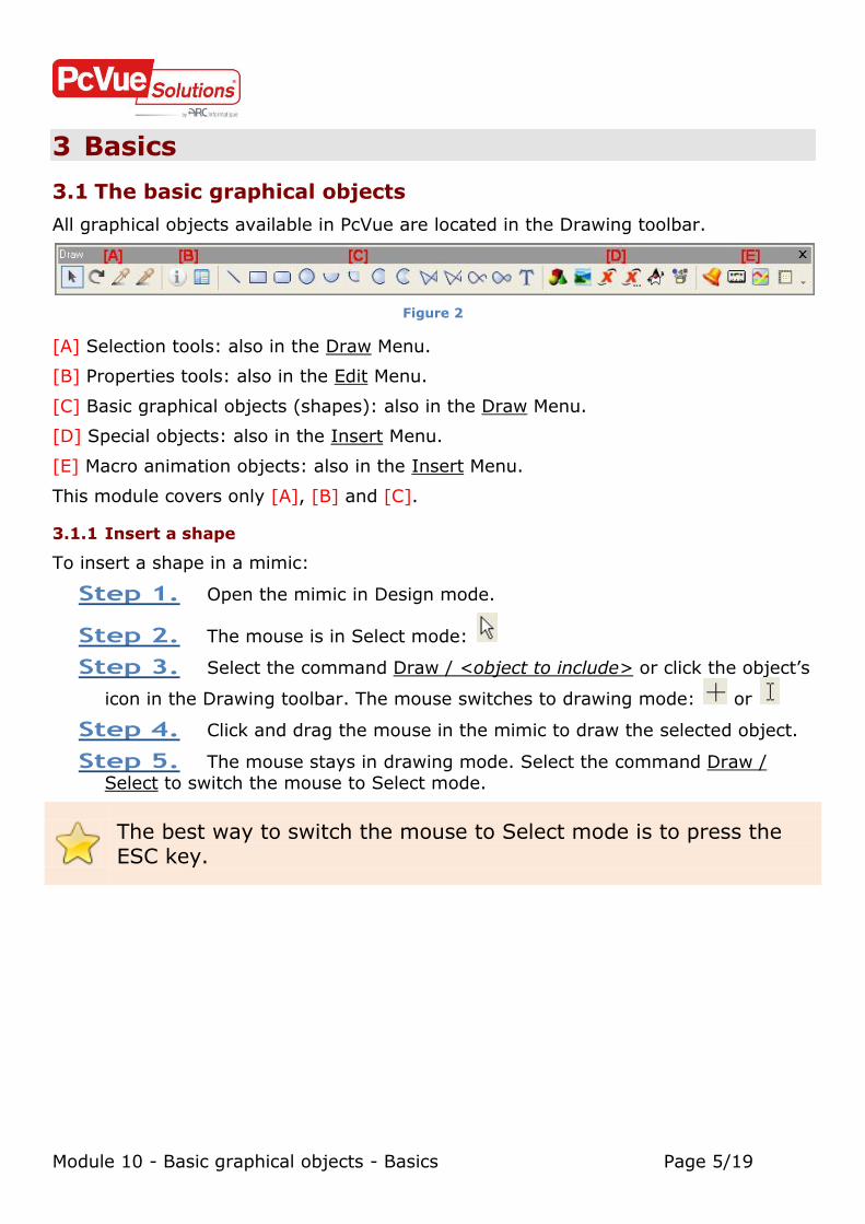
All graphical objects available in PcVue are located in the Drawing toolbar.
Figure 2
[A] Selection tools: also in the Draw Menu.
[B] Properties tools: also in the Edit Menu.
[C] Basic graphical objects (shapes): also in the Draw Menu.
[D] Special objects: also in the Insert Menu.
[E] Macro animation objects: also in the Insert Menu.
This module covers only [A], [B] and [C].
3.1.1 Insert a shape
To insert a shape in a mimic:
Step 1. Open the mimic in Design mode.
Step 2. The mouse is in Select mode:
Step 3. Select the command Draw / <object to include> or click the object’s
icon in the Drawing toolbar. The mouse switches to drawing mode: or
Step 4. Click and drag the mouse in the mimic to draw the selected object.
Step 5. The mouse stays in drawing mode. Select the command Draw / Select to switch the mouse to Select mode.
The best way to switch the mouse to Select mode is to press the ESC key.

Module 10 - Basic graphical objects - Basics Page 6/19
Figure 3
Drag one of the black handles to resize the graphical object.
You can move an object with the mouse after selection. By default when moving, the object “snaps” to the grid. You can disable this function in the Windows properties
(option Display tab / Grid / Enable).
You can move a selected object one pixel at a time using the arrow keys.
3.1.2 Select multiple objects
There are several ways to select multiple objects:
Drag the mouse over the objects you want to select,
Select one object, press and hold the Shift key, select another object and so on.
When several objects are selected you can move them together.

Module 10 - Basic graphical objects - Basics Page 7/19
3.1.3 Duplicate a graphical object
There are several ways to duplicate an object. You can select the object and copy it
by:
Clicking the Edit / Copy command or
Pressing the Ctrl + C key combination or
Right-clicking the object and selecting the Copy command.
Then you can paste the object by:
Clicking the Edit / Paste command or
Pressing Ctrl + V key combination or
Right-clicking where you want to paste it and using the Paste here command.
The best way to copy/paste is as follows: Press the Ctrl key, Select the object and hold down the left mouse button, Drag and drop the object.
Of course, these methods also work when several objects are selected (multiple
selections).

Module 10 - Basic graphical objects - Basics Page 8/19
Exercise 1. Create a new mimic: Basic objects. Insert several basic graphical objects.
“Play” with them (copy, paste, multiple selections…).
Draw a polygon representing a triangle, How many
points have been created? Why?
Right-click on one point of this polygon. What is
displayed?

Module 10 - Basic graphical objects - Basics Page 9/19
3.1.4 Properties of objects
Every graphical object has various properties: color, size, position etc.
There are several ways to display the properties of an object. Select the object and:
Use the Edit / Properties command or
Right-click and select the Properties command or
Double-click on it.
PcVue opens the Properties dialog.
Figure 4
Here, you can change any property you want and click the OK button.
To change the background or the line color:
Step 1. Click (don’t double-click) the color icon. PcVue displays the Colors palette.
Figure 5

Module 10 - Basic graphical objects - Basics Page 10/19
Step 2. Left-click (don’t double-click) the color you want to apply.
There are also Advanced Properties which are hidden by default. To display the
Advanced Properties of an object:
Step 1. Open the Object properties.
Step 2. Click the Advanced Properties button.
Figure 6
This feature will be covered in the Advanced module.
Exercise 2. Change properties of several objects.

Module 10 - Basic graphical objects - Basics Page 11/19
3.2 The Arrange tools
The most of the Arrange tools are located in the Menu Arrange, the Arrange toolbar and via a right-click on a selected object / Arrange.
Figure 7
Figure 8
A description of the Arrange tools is available in the online Help in: Developing the HMI / Drawing / Moving and arranging drawing elements / Arrange toolbar.

Module 10 - Basic graphical objects - Basics Page 12/19
3.2.1 Using groups
After making a multiple selection you can group the objects. Then if you change a
property of the group it is applied to all objects belonging to the group.
3.2.2 Lock objects
If you don’t want to move an object by mistake you can lock it using this tool.
3.2.3 Managing the ordering objects
Every time you insert a new object it is automatically displayed in the top level of the
hierarchy of objects. You can use these tools to change the level of an object.
When one or more objects are drawn on top of one another so that
the objects underneath are invisible, you can select each object in turn by positioning the mouse over the objects and using the TAB key.
3.2.4 Moving and resizing objects
When you are manipulating several objects you often need to align, centre or resize
them in bulk with respect to each another. These tools allow you to do so.
To align, resize or centre objects you must have a reference object. It is highlighted
by black handles as follows:
Figure 9
In this example if you select Align Top the result will be as follows:
Figure 10

Module 10 - Basic graphical objects - Basics Page 13/19
Exercise 3. Use the Arrange tools to group/ungroup, lock/unlock, align, order and resize objects.
3.3 Create a button
To create a button you must select the Button or Colored Button 0ption in the tab
section object properties / Aspect tab / Appearance list.
Figure 11
If you want to change the color of a button in Runtime mode you must select Colored button.

Module 10 - Basic graphical objects - Basics Page 14/19
Exercise 4. Create a normal button.
Try to change the background of the button. Why are
you unable to do so?

Module 10 - Basic graphical objects - Basics Page 15/19
3.4 Using images
The HMI supports the use of images in BMP, JPG, WMF, GIF and animated GIF formats.
The use of images can greatly enhance the appearance of your application, however there are two points which you must always take into account.
Images, particularly those with many colors, use large amounts of memory.
Images frequently use different color palettes. If you display two or more images at
the same time with different palettes, and the graphic adapter you are using does not have sufficient colors to display them, then you will get bizarre effects with the
displayed colors changing from their usual appearance.
3.4.1 Insert an image
Before you can insert an image you must copy it to the correct folder: Project path\B.
To insert an image:
Step 1. Select the command Insert / Image or click the object’s icon in the Drawing toolbar. The Insert Image dialog appears.
Step 2. Select the image needed and click the OK button or drag and drop it
directly on the mimic.
When you copy an image into the project subfolder Project path\B while PcVue is running you will not see it in the Insert Image
dialog!! You must refresh the image list using the Refresh button.
Figure 12

Module 10 - Basic graphical objects - Basics Page 16/19
3.4.2 Transparent color
You can define one of the colors that is used in an image as transparent. That is, you
can see the background of the mimic or any drawing elements under it through any area of that color.
To select the transparent color:
Step 1. Open the tab Properties / Picture of the image object.
Step 2. Select the Transparent color option.
Step 3. Click the color icon to select the transparent color in the colors
palette (see Figure 13) or click directly on the image. The corresponding pixel’s color will become the transparent color (see Figure 14).
Figure 13 & Figure 14

Module 10 - Basic graphical objects - Basics Page 17/19
Exercise 5. Using images:
1. Insert the image ICO_OK.bmp in the mimic.
Select the background as the transparent color. Using the Aspect tab, change the image to the Button appearance
so that it looks like a button.
2. For our project:
Create a new mimic: Floor 1 and save it.
Insert the image Floor1.jpg

Module 10 - Basic graphical objects - Basics Page 18/19
3.4.3 Image from the PcVue Library
PcVue provides a large library of images. To insert an image from the library select
the Library drop-down list in the Insert Image dialog.
Figure 15
Then the way to manipulate the image is the same as described.
You can recognize an image that is from the library by its path displayed in the Image properties / Picture tab.
Figure 16
Exercise 6. Insert the image Misc_Image15.bmp from the MISCELLANEOUS
library.

Module 10 - Basic graphical objects - Basics Page 19/19
4 Summing-up
Using the basic graphical objects you can draw the most common mimics used in a traditional SCADA project.
There are many Arrange tools that enable you to make a complete mimic.
The most common image formats are supported by PcVue.