Embed Size (px)
Citation preview

NOTES
Module 05
Points
In this module, you learn how to work with points in AutoCAD Civil 3D.
Points are single locations in space with attributes such as point number,
northing, easting, elevation, and description. Civil 3D points are represented
by point objects. There are other types of points in Civil 3D. A few examples
include Land Desktop points and AutoCAD points.
Points are one of the most fundamental elements in a site development project.
They can be used to represent existing conditions and proposed construction
locations. Point data that represents existing conditions is usually created from
survey data files. Points used for construction are created by engineers and
construction personnel. Once a design is completed, engineers extract point
data from the design and then send this to the field for construction staking.
Objectives
After completing this module, you will be able to:
Import points to AutoCAD Civil 3D from an external text file.
Assign point styles and point label styles using the description key editor.
Create points using manual input methods.
Organize points by creating point groups.
Edit point data in a table and graphically.
Control the graphical display of point data.
Create a point table that shows point data.

AutoCAD Civil 3D 2009 Education Curriculum NOTES
05-2
Notes
Data for this module resides in the \AutoCAD C3D 2009 Education
Curriculum\Module 05 - Points\ folder.
It is assumed that you have already completed Module 2, which discusses
point styles and point label styles.
Student Exercises
The following exercises are provided in step-by-step format. Open the Civil
3D program prior to beginning the lesson by double-clicking the Civil 3D icon
on your desktop.
You working in the Imperial system should use the drawing files beginning
with the letter I, while those working in the metric system should use the
drawing files beginning with the letter M. You are provided with a drawing
for each exercise in the lesson.
You are also provided with a text file called I_Points.txt (M_Points.txt)
containing point data.
You must use the drawings provided with each exercise.
The exercises in this module are as follows:
1. Import Points from Text File
2. Create Description Keys
3. Create Points Manually
4. Create Point Groups
5. Edit Point Data in a Table and Graphically
6. Use Grips to Control Graphical Point Display
7. Create a Point Table

Module 05 - Points NOTES
05-3
Points
Points are fundamental for civil engineering planning, design, and construction
projects. In common terms, a point represents a singular location in space. It
is usually characterized with an X and Y (easting and northing) coordinate pair
in two-dimensional (2D) space, or an X, Y, and Z (easting, northing, and
elevation) coordinate triplet in three-dimensional (3D) space.
Points are used throughout all phases of a site development project. During
the topographic survey, points are used to represent survey sideshot
observations of existing conditions. The points you work with in Module 05
are existing survey points.
Points are also used during the design process. Engineers often create points
to represent finished design elevations. These points are then connected to
create a plan showing the proposed design. Design points can also be used to
created finished design surface models. For example, an engineer may create
points to represent the proposed grading scenario for a subdivision design
project.
Finally, points are used during the construction phase of a project. Points
created during the design are uploaded to GPS and Total Station survey
equipment, and used for construction staking.
There are a few ways to represent points in AutoCAD Civil 3D.
1) AutoCAD Points
2) Land Desktop Points
3) AutoCAD Civil 3D Point Objects
The AutoCAD point is a singular AutoCAD entity with no intelligence.
Inherent properties of an AutoCAD point entity are the X, Y, and Z coordinate
values. AutoCAD points can be used to create surface models if they have a
representative Z insertion coordinate.
Land Desktop is the predecessor to Civil 3D. Land Desktop points are point
objects and can be used in Civil 3D if necessary.
The most common way to represent a point in Civil 3D is the point object. The
point object is an intelligent object with the following properties:
Number
Description
Elevation

AutoCAD Civil 3D 2009 Education Curriculum NOTES
05-4
Northing
Easting
Point objects are as shown:
The Civil 3D point object consists of a marker and a label. The display of the
marker is controlled with a point marker style. In this illustration, you can see
how different marker styles can be used to show different types of points. The
display of the label is controlled with a point label style. Different label styles
can be used to show specific point data.
Key Terms
Point A point is a singular location in space. A 2D point is a location on a plane and
identified with an X,Y coordinate pair. A 3D point adds an elevation
coordinate and is identified with an X, Y, and Z coordinate triplet. Points are
used to represent existing and proposed features.
Point Group A point group is a collection of similar points in Civil 3D. Point groups can be
created using both inclusion and exclusion criteria. You can create point
groups based on point number range, descriptions, graphical selection, and
elevation ranges. Point groups are useful for manipulating large groups of
points with a single edit. You can assign point styles and point label styles to
point groups. Point groups are required for surface modeling.
Point Style The point style controls the display of the point node. You can use AutoCAD
blocks to create customized point styles for different types of points.
Point Label
Style
The point label style controls the display of the point label. You can create
different point label styles to show different types of point data.
Raw
Description
The raw description is the description a surveyor assigns to a point in the field.
Raw descriptions are abbreviated alpha or numeric descriptions. Surveyors

Module 05 - Points NOTES
05-5
prefer these types of descriptions because it simplifies the actual entry of the
description in the field.
Full
Description
The full description is an alternative point description that is assigned to a
point. The full description expands on the abbreviated or numeric raw
description assigned by the surveyor. Civil 3D description keys automatically
assign a full description to a raw description.
Description
Keys
Description keys are lookup tables in Civil 3D that automatically assign a full
description to points. They also automatically assign point styles and point
label styles to points. Description keys are stored in a description key set.
Survey Point A survey point is created from the survey database. Survey points are edited by
making modifications to the survey observation data. When you change survey
observation data, survey points are updated. Survey points appear with a
symbol in the point list.
Manually
Created
Point
A manually created point is created using a number of different point creation
tools. Manually created points can be edited directly and appear with a
symbol in the point list.
Reduced
Coordinates
Reduced coordinates are created from survey observation data. Reduced
coordinates indicate northing, easting, and elevation.

AutoCAD Civil 3D 2009 Education Curriculum NOTES
05-6
EXERCISE 1: IMPORT POINTS FROM TEXT FILE
In this exercise, you import points from an external text file to the drawing.
The point data used in this module was collected by survey crews. The
designers then realized that additional points are required near the south end of
the site for the design. These additional points reside in the text file.
Points that reside in a text file are usually represented with reduced
coordinates. Text files containing point data can use a number of different
formats. The format used in this exercise is PNEZD (Comma Delimited). An
explanation of the file contents is as follows:
P – Point Number
N – Northing
E – Easting
Z – Elevation
D – Description
If point numbers are not provided in a text file, Civil 3D will automatically
assign point numbers for you.
For this exercise, open …\Module 05 – Points\I_Points-EX1.dwg (M_Points-
EX1.dwg).
You first review the point data file.
1. Using Windows Explorer, browse the \AutoCAD C3D 2009 Education
Curriculum\Module 05 - Points\ folder.

Module 05 - Points NOTES
05-7
2. Open I_Points.txt (M_Points.txt) using any text editor.
3. Note the format of the data in the text file.
The values represent point number, northing, easting, elevation, and
description and are separated by commas.
4. Close the text editor.
Now you import the points to the drawing.
5. Zoom to the south end of the southernmost intersection.
Notice that there are no trees or ground shots in the vicinity.
6. Click Points > Create Points.
The Create Points toolbar contains commands to create points using a
number of different methods.
7. Click the down arrows on the toolbar buttons and review the commands
available for creating points.

AutoCAD Civil 3D 2009 Education Curriculum NOTES
05-8
8. Click Import Points on the right side of the toolbar.
9. Click the drop-down list and ensure the format is set to PNEZD (comma
delimited).
10. Click Add File and browse to the \AutoCAD C3D 2009 Education
Curriculum\Module 05 - Points\ folder.
11. Select I_Points.txt (M_Points.txt).
12. Click Open.
13. Select Add Points to Point Group.
14. Click to create a new Point Group.
15. Enter Additional Survey Data.

Module 05 - Points NOTES
05-9
16. Click OK.
17. Click OK to import the points.
Civil 3D creates several ground points (description = GP) and tree points
(descriptions = TRL and TRR) in the drawing.
18. Review the point data in the drawing.
19. Close the Points toolbar.
20. In Toolspace, click the Prospector tab.
21. Click the plus sign (+) and expand the Point Groups tree.
22. Click Additional Survey Data.
Civil 3D displays the point data in the Item View area of the Toolspace
Window.

AutoCAD Civil 3D 2009 Education Curriculum NOTES
05-10
23. Right-click any of the points in the Item View window and select Zoom
To in order to inspect the additional point added.
24. Close the drawing and do not save the changes.

Module 05 - Points NOTES
05-11
EXERCISE 2: CREATE DESCRIPTION KEYS
Description keys are used to automate the base plan creation process. Description keys are
“lookup” tables assigned to points’ field descriptions (Raw Description) to do the following:
Assign an alternative description (Full Description) to the point.
Assign a point style to each point.
Assign a point label style to each point.
Scale and rotate points based on additional description parameters.
The dataset for this module contains point data shown with symbols in the drawing.
Automatic symbol assignment is accomplished using description keys. Description keys are
located in a description key set.
In this exercise, you create additional description keys in an existing description key set.
For this exercise, open …\Module 05 – Points\I_Points-EX2.dwg (M_Points-EX2.dwg).
Begin by reviewing the existing description key set.
1. In Toolspace, click the Settings tab.
2. Expand the Point and Description Key Sets trees.
Notice the existing description key set named City of Vancouver.
3. Right-click City of Vancouver and click Edit Keys.
The Panorama window shows the DescKey Editor with the existing description keys.
4. Right-click any column header and clear every column except Code, Point Style, Point

AutoCAD Civil 3D 2009 Education Curriculum NOTES
05-12
Label Style, and Format.
Add a description key for catch basins.
5. In the Panorama window, right-click any description key and click New.
A new description key entry appears at the bottom of the Panorama window.
6. Click the row for the new description key, and for Code, enter CB.
7. Select Point Style and select STM CB in the Point Style dialog box. Click OK.
8. Select Point Label Style and select Description Only. Click OK.
9. Change the format to CATCH BASIN and press ENTER.
10. Click the green check mark to close the Panorama window and save the changes.
11. Close the drawing and do not save the changes.

Module 05 - Points NOTES
05-13
EXERCISE 3: CREATE POINTS MANUALLY
In some circumstances points need to be manually added to the drawing because the survey
data is incomplete. The location of manually created points is often identified by a position
relative to two other points, or a position relative to an intersection curb return.
In this exercise, you add catch basin points on the curb returns of an existing intersection.
For this exercise, open …\Module 05 – Points\I_Points-EX3.dwg (M_Points-EX3.dwg).
First navigate the graphics to the area where the points are needed.
1. In Toolspace, click the Prospector tab.
2. Click the Points tree.
3. Click the Point Number column header in the Item View window to sort the points by
point number.
4. Scroll down to point 342.

AutoCAD Civil 3D 2009 Education Curriculum NOTES
05-14
5. Right-click 342 and click Zoom To.
Civil 3D zooms to show point 342.
6. Use the mouse wheel and zoom out slightly.
Notice points 350 and 351 on the northwest corner of the intersection. Also notice
points 279 and 280 on the southwest corner of the intersection.
Catch basin points are required on the curb returns midway between these points.
7. Click Points > Create Points.
8. Click the first icon drop-down arrow and select Manual.
9. With your cursor in the graphics area, press SHIFT, right-click, and click Midpoint.
10. Hold the mouse over the polyline running between points 350 and 351.
11. When you see the triangular midpoint object snap marker, click the polyline.

Module 05 - Points NOTES
05-15
12. For a point description, enter CB. Press ENTER.
13. For the elevation, enter 268.6’ (81.8 m). Press ENTER.
14. Repeat the step and add a CB point between 279 and 280 using the elevation 267.5’
(81.5 m)
15. Press ENTER to end the command.
Civil 3D creates two catch basin points. Notice that the point style shows the catch
basin symbol and the point label style shows just the description.
16. Close the Create Points toolbar.
The description key created in the previous exercise automatically assigned the point
style and the point label style to the points.
17. Close the drawing and do not save the changes.

AutoCAD Civil 3D 2009 Education Curriculum NOTES
05-16
EXERCISE 4: CREATE POINT GROUPS
Site development projects usually involve thousands of points. These points are used for a
number of civil engineering tasks including survey data reduction, base plan creation,
surface modeling, design, and construction. Point data management becomes a task itself.
Point groups are used to organize points based on common properties. You can create point
groups using a number of different criteria including description, point number, graphical
selection, and elevation ranges. You can even create point groups from other point groups.
Point groups are also required for surface definition. In this exercise, you organize point
data by creating point groups.
For this exercise, open …\Module 05 – Points\I_Points-EX4.dwg (M_Points-EX4.dwg).
1. In Toolspace, click the Prospector tab.
2. Click the plus sign (+) to expand the Point Groups tree.
Notice the Additional Survey Data point group and the _All Points point group. The
_All Points point group always exists, is not editable, and contains all of the points in the
drawing.
You now create a point group for the pavement edges.
3. Click the _All Points point group.
4. In the Item View area of the Toolspace window, adjust the columns so that you see Point
Number, Northing, Easting, Raw Description, and Full Description.
5. Click the Raw Description column header to sort the list by Raw Description.
6. Scroll down to the edge of pavement shots.
The edge of pavement shots have a raw description of EPL and EPR.

Module 05 - Points NOTES
05-17
You now create a point group for the pavement edges, which includes points with the
EPR and EPL descriptions.
7. Right-click the Point Groups tree.
8. Click New.
9. Click Information.
10. For Name, enter Existing Pavement Edges. Click Apply.
11. Click Raw Desc Matching.
12. Select EP*.

AutoCAD Civil 3D 2009 Education Curriculum NOTES
05-18
The Raw Desc Matching tab shows entries in the description key set. It is easier to create
point groups when a description key set exists.
13. Click the Include tab.
Notice that With Raw Descriptions Matching is toggled on and that there is an EP*
entry.
Alternatively, you could go directly to the Include tab, select With Raw Descriptions
Matching and enter EP*.
The asterisk (*) is a wildcard indicating that all descriptions with an EP prefix are
included. Alternatively, you could enter EPR, EPL.
14. Click the Point List tab and observe that the points with descriptions EPL and EPR have
been included in the point group.
15. Click OK.
A new point group is created and appears under the Point Groups tree.
16. Right-click Existing Pavement Edges.
17. Click Properties.
18. Explore the Point Group Properties dialog box.
19. Click Cancel.
20. Right-click Existing Pavement Edges and note the other menu options.
Now you create a point group for surface modeling.
21. Right-click the Point Groups tree.
22. Click New.

Module 05 - Points NOTES
05-19
23. Click Information. For Name, enter EG Surface.
24. Click the Exclude tab.
25. Select With Raw Descriptions Matching.
26. Enter MON*, LP, FH*.
An exclusion criterion is used to exclude certain points from the surface model. These
points are the monuments, lead plugs, and fire hydrants. The elevations of these points
are not suitable for surface modeling because they do not adequately represent the
existing terrain elevation.
27. Click Point List and note that these points are not in the list.
28. Click OK.
29. Close the drawing and do not save the changes.

AutoCAD Civil 3D 2009 Education Curriculum NOTES
05-20
EXERCISE 5: EDIT POINT DATA IN A TABLE AND GRAPHICALLY
In some circumstances, it is necessary to edit point data. You may need to edit point data to
change the descriptions or change elevations based on updated information from the
surveyor, or you may be using design points for grading purposes.
There are a number of methods for editing point data in AutoCAD Civil 3D. You can edit
point data graphically or you can edit point data in a tabular format.
In this exercise, you learn how to edit point data in a table and graphically.
For this exercise, open …\Module 05 – Points\I_Points-EX5.dwg (M_Points-EX5.dwg).
1. In Toolspace, click the Prospector tab.
2. Right-click Points and click Edit Points.
Civil 3D shows all the points in the Point Editor of the Panorama window.
3. Right-click any column header and make only the following columns visible:
Point Number
Northing
Easting
Point Elevation
Raw Description
Full Description

Module 05 - Points NOTES
05-21
4. Click and drag the column headers to the left and right so that the order is the same as
shown in the previous illustration.
Next, you modify points.
5. Scroll down to point 38.
6. Right-click point 38 and click Zoom To. Civil 3D shows the location of point 38 in
the drawing area.
7. Click Raw Description and change the value to TRR .5D. Press ENTER.
8. Click the green check mark to close the Panorama window.
9. Notice that point 38 in the graphics display updates with the new description.
You may need to enter REGEN at the command line to see the screen change.
10. Click and select point numbers 179, 297, 37, and 35 in the drawing area.
The points are displayed as selected.

AutoCAD Civil 3D 2009 Education Curriculum NOTES
05-22
11. Right-click and note the menu options.
Aside from standard AutoCAD commands, there are commands specific to point
manipulation.
12. Click Edit Points.
The four selected points are shown in the Point Editor of the Panorama window and can
be edited simultaneously.
13. Click the green check mark to close the Panorama window.
You now change the description for several points.

Module 05 - Points NOTES
05-23
14. In Toolspace, click Points.
15. In the Item View area of Toolspace, click the Point Number column and sort the data by
point number in increasing order.
16. Scroll down until you see points 167 through 170.
17. Click point number 167.
18. Hold the Shift key down and click point 170.
Points 167 through 170 are selected.
19. Right-click over the selected points and click Edit Points.
Civil 3D shows the points in the Point Editor of the Panorama window.
20. Right-click the Raw Description column header and click Edit.
21. In the first Raw Description cell, change the value to TRL 1D. Press ENTER.
The D represents diameter. Notice that the description of all the points changes.
22. Click the green check mark to close the Panorama window.
23. Close the drawing and do not save the changes.

AutoCAD Civil 3D 2009 Education Curriculum NOTES
05-24
EXERCISE 6: USE GRIPS TO CONTROL GRAPHICAL POINT DISPLAY
In AutoCAD Civil 3D, drafting is a direct by-product of the design process.
Points are useful for base plan creation, surface modeling, and design tasks. In
many circumstances points are also used on plotted drawings to portray both
existing conditions and the design.
In this exercise, you learn how to graphically control the display of point
objects in Civil 3D.
For this exercise, open …\Module 05 – Points\I_Points-EX6.dwg (M_Points-
EX6.dwg).
1. In Toolspace, click the Prospector tab.
2. Click Points.
3. In the Item View area scroll to point number 771.
4. Right-click 771 and click Zoom To.
Module 05 - Points NOTES
05-25
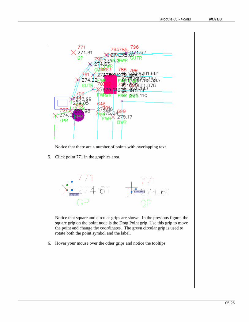
Notice that there are a number of points with overlapping text.
5. Click point 771 in the graphics area.
Notice that square and circular grips are shown. In the previous figure, the
square grip on the point node is the Drag Point grip. Use this grip to move
the point and change the coordinates. The green circular grip is used to
rotate both the point symbol and the label.
6. Hover your mouse over the other grips and notice the tooltips.

AutoCAD Civil 3D 2009 Education Curriculum NOTES
05-26
The Drag Label grip enables you to drag the entire label away from the
point. The Toggle Subitem grip enables you to move the point attributes
independently.
7. Click the square drag label grip and drag the entire label away from the
point.
8. Right-click and click Reset Label to restore the label to its original
location.
9. Click the point again to show the grips.
10. Click the circular Toggle Subitem grips.
11. Click a blue diamond grip.
12. Move the mouse to a new location and click again.
You may want to turn off object snaps for more accurate placement. Civil
3D moves the individual sub item to a new location.

Module 05 - Points NOTES
05-27
13. With the point still selected, right-click and click Reset Label.
14. Close the drawing and do not save the changes.

AutoCAD Civil 3D 2009 Education Curriculum NOTES
05-28
EXERCISE 7: CREATE A POINT TABLE
In some circumstances it is useful to create a point table in the drawing to show point data.
In this exercise, you create a point group for survey control and then display the survey
control point group data in a point table.
For this exercise, open …\Module 05 – Points\I_Points-EX7.dwg (M_Points-EX7.dwg).
First create the Survey Control point group.
1. In Toolspace, click the Prospector tab.
2. Right-click Point Groups and click New.
3. Click the Information Tab. For Name, enter Survey Control.
4. Click Apply.
5. Click Raw Desc Matching.
6. Select LP and MON*.

Module 05 - Points NOTES
05-29
7. Click Point List to verify the data.
8. Click OK.
Now create the point table.
9. Enter ZE (Zoom Extents) on the command line. Press ENTER to zoom to the extents
of the drawing.
10. Click Points > Add Tables.
11. Make sure the Table style is PNEZD format.
12. Click the icon to the left of No Point Groups Selected.
13. Select Survey Control in the Point Groups dialog box and click OK.
14. Click OK again.
15. Click a point in the drawing.
Civil 3D creates a point table in the drawing that shows the point data. The table is
dynamic. This means that if the point data changes, the table automatically updates.

AutoCAD Civil 3D 2009 Education Curriculum NOTES
05-30
16. Close the drawing and do not save the changes.

Module 05 - Points NOTES
05-31
Questions
1. Name three methods for creating points in AutoCAD Civil 3D.
2. What controls the display of the point node?
3. What controls the display of the point label?
4. Why would an engineer use point groups on a civil engineering project?
5. What is a common use for point groups?
6. Name three criteria you can use to create a point group.
7. Explain the difference between raw and full point descriptions.
8. Name three specific functions of description keys.
9. Explain why an engineer would want to use description keys.
10. When you select a point graphically, a square grip and circular grip appear.
Explain the significance of these grips.
Answers
1. To create points in Civil 3D, you can manually create points, import points
from an external text file, or you can create points from a survey database.
2. The point style controls the display of the point node.
3. The point label style controls the display of the point annotation.
4. A civil engineering project typically involves thousands of points. Point
groups allow engineers to organize points with similar characteristics.
5. A common use for point groups is surface modeling.
6. You can create a point group using point number ranges, descriptions, and
elevation ranges.
7. The raw description is used by surveyors to assign descriptions to points.
The raw description is usually an abbreviated or numeric description. The
full description is used in the office and expands on an abbreviated raw
description.
8. Description keys assign point styles, point label styles, and alternate or full
descriptions to points.

AutoCAD Civil 3D 2009 Education Curriculum NOTES
05-32
9. Description keys assist with the automatic creation of the pre-engineering
base plan.
10. The square grip is the Drag Label grip. This enables you to drag the entire
label away from the point. The circular grip is the Toggle Subitem grip.
This enables individual grips for the point attributes. The individual grips
enable you to drag the individual attributes away from the point. The
second circular grip is the Rotate Point grip, which is useful for rotating
the point marker symbol.
Module 05 - Points NOTES
05-33
Module Summary
In this module, you learned how to work with points in AutoCAD Civil 3D.
At the beginning of the module, the drawing contained points created from
Civil 3D survey functionality. The next step was to import points from an
external text file.
You then created description keys to automatically assign a point style, assign
a point label style, and assign an alternate description. The next steps
involved manually creating points and point groups.
Finally, you learned how to edit point data graphically and tabularly, control
graphical point display with grips, and create a point table.