Embed Size (px)
Citation preview

Modulation and Demodulation
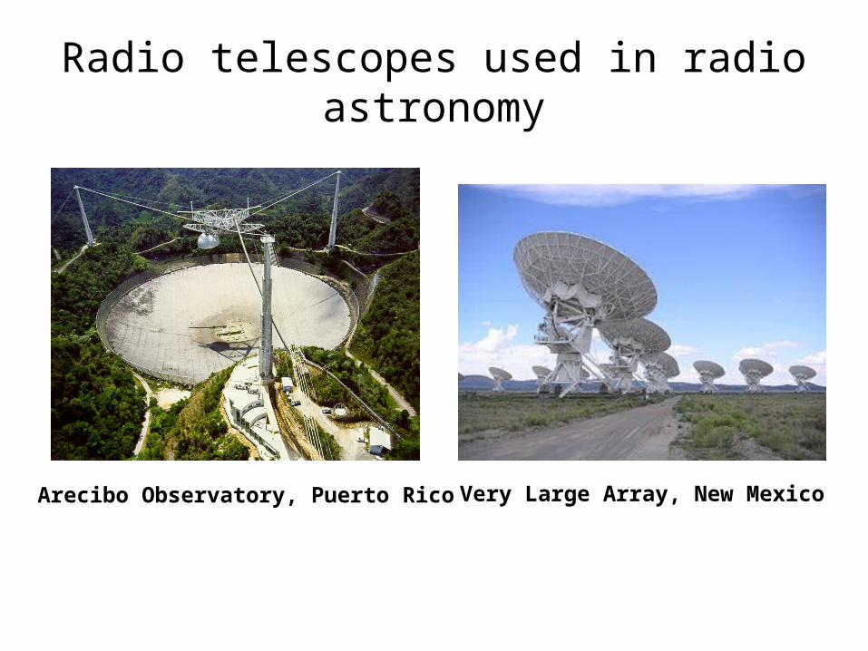
Radio telescopes used in radio astronomy
Arecibo Observatory, Puerto Rico Very Large Array, New Mexico

As in movies
• Contact– https://www.youtube.com/watch?v=C9DuMK0uo
1c• Goldeneyes
– https://www.youtube.com/watch?v=MH2qnn4D0kY
3

Why Do We Need A Large Radio Telescope like This?
• Difficulties in low frequency communications– Many astronomical objects emit radiation at radio
frequency (RF)• RF is much small than the frequency of visible lights
– Antenna size: the same magnitude of the wavelength of a signal
– Low frequency signals require large antennas.
f *l = c (speed of light)
We need a way to transmit and receive low frequency signals easily!
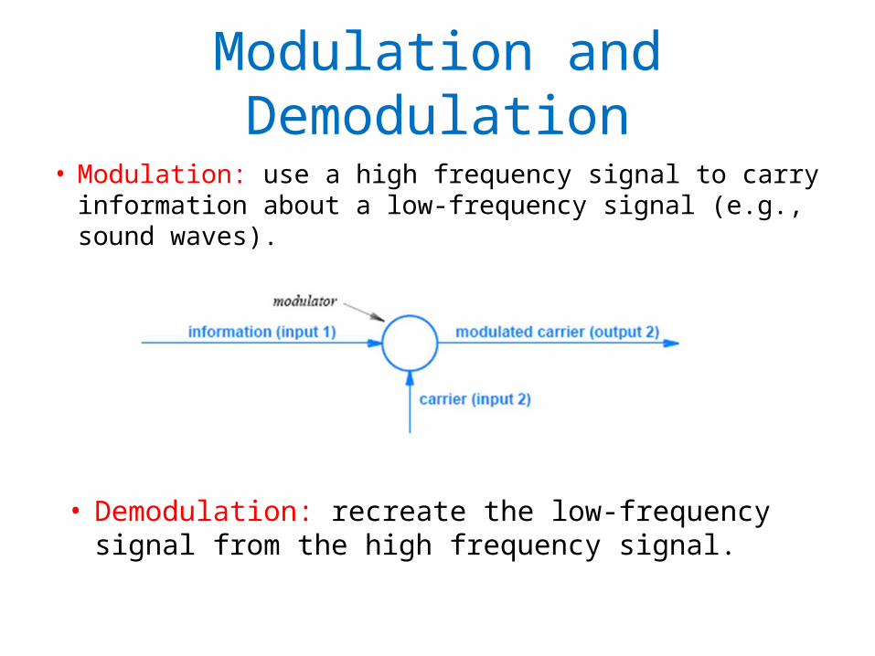
Modulation and Demodulation
• Modulation: use a high frequency signal to carry information about a low-frequency signal (e.g., sound waves).
• Demodulation: recreate the low-frequency signal from the high frequency signal.

More Motivation for Modulation
• Interference– Signals occupy similar frequency bands
• TV, radio stations
• Modulation: allow different signals to be transmitted simultaneously with a single device– Radio and TV channels: with different frequencies.
7
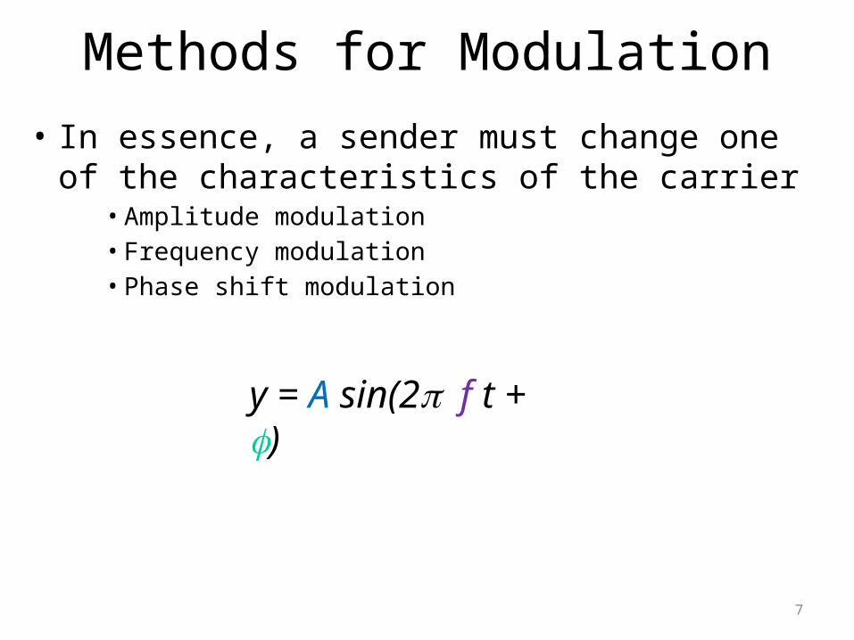
Methods for Modulation
• In essence, a sender must change one of the characteristics of the carrier
• Amplitude modulation• Frequency modulation• Phase shift modulation
y = A sin(2 p f t + f)

8
Amplitude Modulation (AM)
• The amplitude of a carrier is modified in proportion to the information signal.– The frequency of the carrier is fixed.
carrier
information

Example
• The original signal: sin(x)• The carrier: sin(35x)
• Multiplication – sin(x) * sin(35x)

10
Problems of Amplitude Modulation• Power level to zero
• Practical systems do not allow for a modulated signal to approach zero
• In practice, modulation only changes the amplitude of a carrier slightly– Keeping the carrier wave near maximum

Example
• The carrier: sin(35x)• The signal: sin(x)
• AM with a modulation index a– [ a * sin(x) + mi ] * sin (35x)
• a = 0.3, mi =1
12
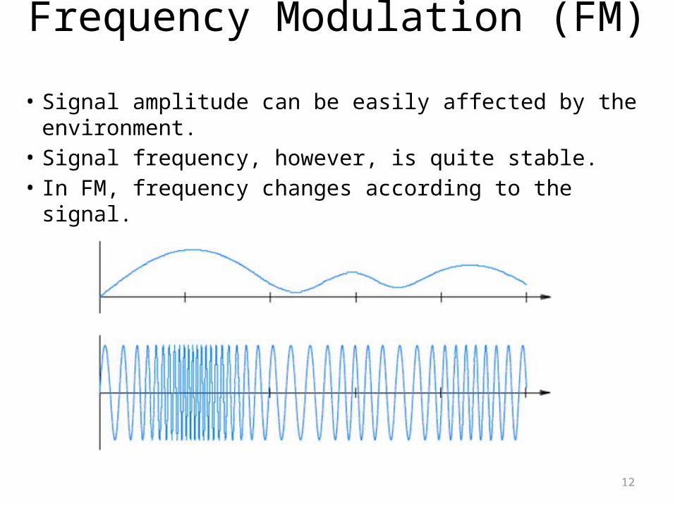
Frequency Modulation (FM) • Signal amplitude can be easily affected by the
environment. • Signal frequency, however, is quite stable.• In FM, frequency changes according to the signal.

13
Frequency Modulation (FM) • The carrier: sin(5t)• The signal: sin(t)
• FM– sin ( (sin(t) + 2) * 5 t)
Q: Is the constant “2" necessary here?

14
Modulation of Digital Signals • A different term: shift keying
– Instead of a continuum of possible values, digital shift keying has a fixed set
• Mapping to the power levels of a digital signal

15
a carrier wave
a digital input signal
amplitude shift keying
frequency shift keying

Exercise: ASK
Consider the input signal with 3 levels shown above. Assume we want to use the following sine wave as the carrier.
10 sin(2 p 2 t)
And we want to use the following ASK scheme – 15V level ‘1’– 10V level ‘0’– 5V level ‘-1’
Please draw the resulting waveform after modulation.

Exercise: FSK
Consider the input signal with 3 levels shown above. Assume we want to use the following sine wave as the carrier.
10 sin(2 p 2 t)
And we want to use the following FSK scheme – 3Hz level ‘1’– 2Hz level ‘0’– 1Hz level ‘-1’
Please draw the resulting waveform after modulation.

Efficiency Issues of ASK and FSK
• Must capture the amplitude or frequency information of the carrier– Require at least one cycle of a carrier wave to send a
single bit– Transmission capacity is limited by the carrier frequency!
• A single sine wave circle– One amplitude– One frequency– Can be shifted with multiple phases!

19
Phase Shift Keying (PSK) • Almost every real world modem use PSK to send
more bits.– PSK changes the phase of the carrier wave abruptly.– Each such change is called a phase shift
• On a sine wave, each point correspond to a phase (angle)
0°
90°
180°
270°
360°

Calculating the Phase Shift
20
• Example: • The first change:
• Point A’s phase: 90°• Point B’s phase: 270°• Phase change: 270° - 90° = 180°
• The second change:• 360° - 180° = 180°
• The third change?
A
B
A BA B

Calculating the Phase Shift
• Step 1: Identify the two points A & B involved in this phase shift
• Step 2: Find the phase of A & B• Step 3: phase shift = B’s phase – A’s phase

22
Phase Shift and a Constellation Diagram
• How to encode data into phase shifts?– A sender and receiver can agree on the number of
bits per second– Use different phase shifts to denote the data bits.
• A constellation diagram is used to express the exact assignment of data bits to specific phase changes
23
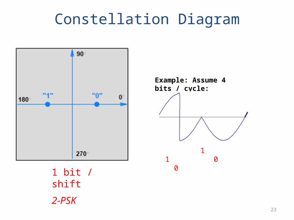
Constellation Diagram
Example: Assume 4 bits / cycle:
1 1 0 0
1 bit / shift
2-PSK
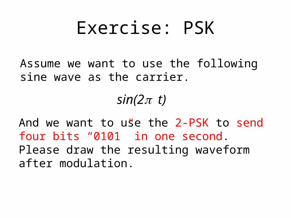
Exercise: PSK
Assume we want to use the following sine wave as the carrier.
sin(2 p t)
And we want to use the 2-PSK to send four bits “0101” in one second. Please draw the resulting waveform after modulation.
25
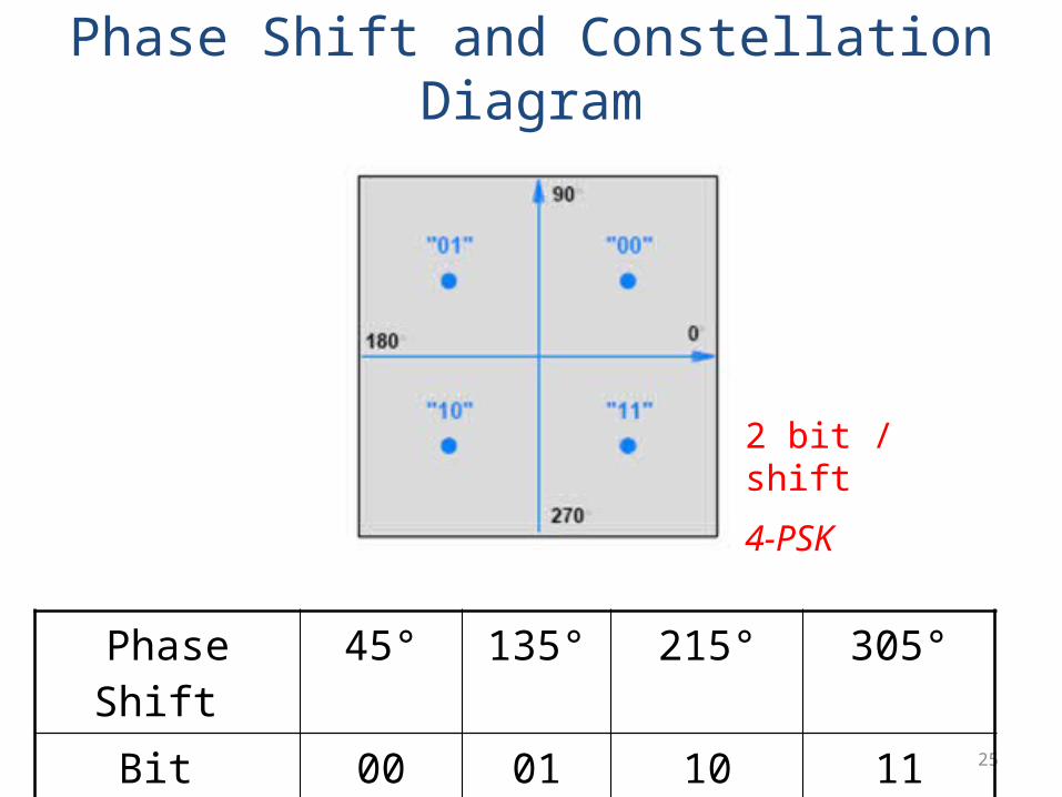
Phase Shift and Constellation Diagram
Phase Shift 45° 135° 215° 305°
Bit Value 00 01 10 11
2 bit / shift
4-PSK

26
Phase Shift and a Constellation Diagram
• In theory, it is possible to increase the data rate by decreasing the angular difference between phases– 4-PSK 8-PSK
• 90° 45°
– 16-PSK: 22.5°
• Noise and distortion limit the ability of practical systems to distinguish among arbitrarily small differences in phase changes.

27
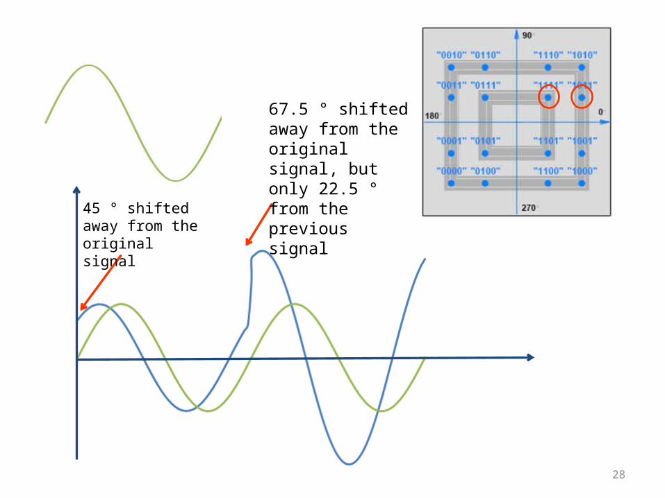
Quadrature Amplitude Modulation (QAM)
• ASK + PSK• In a constellation diagram, we use distance from
the origin as a measure of amplitude
16QAM
28
45 ° shifted away from the original signal
67.5 ° shifted away from the original signal, but only 22.5 ° from the previous signal

29
MODEM: MOdulator + DEModulator
• Usually within the same device– Each location needs both a modulator to send data
and a demodulator to receive data.– Most communication systems are full duplex.
After Class Reading
• Sections 10.14 – 10.16: Dial-up models and QAM