Embed Size (px)
Citation preview
1
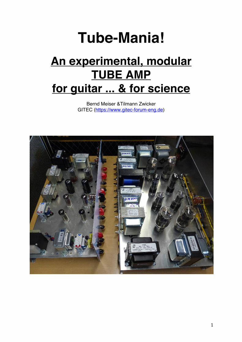
Tube-Mania!
An experimental, modular TUBE AMP
for guitar ... & for science
Bernd Meiser &Tilmann Zwicker GITEC (https://www.gitec-forum-eng.de)

2
1. Introduction Before he founded GITEC (https://www.gitec-forum-eng.de), Prof. Manfred Zollner (https://www.gitec-forum-eng.de/landing-page-news/vorstand/) had been teaching acoustics and signal processing at the university in Regensburg, Germany, from 1990 to 2015. Running the acoustics lab at the university in the framework of this task, he started to take an academic, in-depth scientifically look into the electric guitar and its amplification around 1999. Given the significance that tube amplification plays in the guitar world, he decided to put together an experimental setup that would enable him and his co-workers to investigate all elements of the tube amplifier in detail. Since some sources (especially magazines) stress the differences between certain circuits, between tubes types and tube manufacturers, and between other important components, he also made sure that comparisons could easily be done. The result was a pretty impressive (and huge) modular guitar amp that makes possible, for example, direct comparison between 4 different types of output tubes in connection with 10 different output transformers (from marginally dimensioned low-cost types to expensive high-end brand-products) – all this via immediate, direct switching! Listening tests often lead to unexpected surprising revelations ... The modular tube guitar amp (with most modules shown in Fig 1) has been a mainstay in lab experiments, and it has been exhibited (in action!) at the Guitar Summit 2018 in Mannheim, Germany, and at GITEC Meetings in Regensburg. We will describe this amazing contraption below.
Fig 1: Prof. Zollner's Modular Tube Guitar Amplifier. Modules clockwise from top right: preamp, tone-control/volume/recovery, driver/phase-splitter, 2 x power supply (for 15W and 50W power amps, 50 power amp. Not shown: 15W-power-amp and dummy-load modules.

3
2. Pre-Amplifier Module Let's start with the pre-amplifier module (Fig. 2). Its main objective is the comparison between preamp tubes. No less than 6 such tubes can be included, operating in identical circuits. The corresponding signal paths are instantly selectable via a rotary switch making for the possibility of a very meaning comparison. Using further switches, the cathode resistor of each tube circuits can be selected from three typical values in order to make different operating points available. Correspondingly, the plate (anode) resistor can be selected from two typical values.
Fig. 2: Preamplifier module. It includes 6 identical preamp stages selectable via a rotary switch. When we looked and listened to the module, 6 tubes of the 12AX7 type were installed. They were from different price ranges, sourced from different manufacturers, and included NOS-types, as well. Fig. 3 shows the frequency responses of the 6 circuits. They were in the typical configuration, employing a plate resistor of 100 kΩ and a cathode resistor of 1.5 kΩ connected to a large cathode capacitor (22 µF). To match the most common operating situation, the signal was fed to the circuits via a series resistor matching what we find on all the classic Fender, Marshall, and Vox amps when the high-sensitivity input is used: two 68 kΩ resistors connected in parallel. Signal levels were chosen to approx. match the usual linear operating mode that is found with most single coil pickups feeding an amp.
Fig. 3: Frequency responses of six preamplifier tubes

4
It is interesting to see that the upper cutoff frequency (i.e. the frequency where the gain drops off by 3 dB) is about 12 kHz for all tubes. This is due to the Miller capacitance that gets in the way of the theoretical frequency range of these tubes that extends way into the MHz-range. In this setup, we were not able to perceive any sound difference between the various tubes at all. This is in agreement with what the frequency responses show: the human auditory system is not able to distinguish between signals that differ by less than 1 dB. Comparing further tubes, it does turn out that there can be differences in the gain that may be perceivable if the difference exceeds 1 dB. This will however not have any impact on the actual sound of that tube stage - although increased gain may of course drive subsequent tube stages into (more) saturation and thus create a difference in sound there. Further info on tube preamplifier stages for guitar amps can be found in Physics of the Electric Guitar Chapter 10.1 3. Tone-Control-, Volume-, and Gain-Recovery-Module Following the first preamp-stage, the signal goes to the next amp section comprising tone and volume controls, and (where necessary) a gain-recovery stage. The corresponding module (see Fig. 4) features 4 signal paths - again selectable via a rotary switch. The 4 paths are: - Fender-type tone stack and volume control - Vox-type tone stack with volume control and an extra "Middle" control - Marshall-type tone stack and volume control - Fender-type volume control found in particular in early Fenders where capacitors connected around the volume-control made for volume-dependent tone changes.
Fig. 4: Tone-Control-, Volume-, and Gain-Recovery-Module. The rotary switch on the right selects from the 4 signal paths. All signal paths feature various toggle switches to select component values as they were used in the different amp models or different model years of the same amp type.

5
As such, every period-correct Fender, Vox or Marshall tone control stage can be emulated. It is easy to switch e.g. from a 5F6-A Bassman tone stack to an AB763 Super Reverb circuit, or from a JTM45 to a 1959-Super-Lead. The same holds for "bleed"-capacitors as they are used across volume controls for a "Bright"-effect. The recovery gain stages feature selectable cathode resistors. Of particular interest is of course the cathode-follower recovery stage in Marshall and Vox amps. Here, distortion does occur and corresponding sound changes may be perceivable - this being a much-discussed topic today. Switching between the different tone control sections offered by the module does reveal differences in the tone shaping – but they are surprisingly small. There seems to be no specific "character". The possible amount of change seems a bit stronger in the Fender- and Vox-type circuits, while the Marshall-type circuit has a little less signal loss. For more info, see e.g. Physics of the Electric Guitar, Chapter 10.3. In the extreme positions of the controls, the differences in the handling of the middle frequencies are evident, as are the different locations of the slopes of the bass and treble controls are positions. It proves to be relatively easy to make the signal paths sound very similar. The effect of the circuit around the volume control (already mentioned above) merits some elaboration because it can make for drastic changes in the treble response of an amp dependent on the volume setting. Turning the volume down on the amp may therefore have a completely different effect compared to turning down the volume control on the guitar (the latter having distinct influences in itself - see the previous article on the interaction between pickups, guitar circuitry and cable!). It is important to have an understanding of these influences in order to take advantage of the possibilities, or to avoid any connected issues. Fig. 5 shows the effect of the mentioned "bleed"-capacitors around the volume control of an amp - in this case specifically of a Marshall. Most Marshalls from back in the day were available as "Lead", "Bass", "Organ", and PA versions, and these versions mainly differed in the components (capacitors) found around the volume control. Our modular amp allows for all associated variations.
Fig. 5: Effects of various capacitors connected around the volume control of a Marshall amp.

6
Not all of the classic guitar amps include a gain-recovery stage subsequent to the tone-control/volume circuitry. In particular the very old amplifiers (e.g. Fender amps form the early 1950's) had a very simple tone control that took away only little of the signal level – the signal coming from the tone and volume controls could therefore be fed directly to stage driving the power-amp. 4. Driver (or Phase-Inverter) Module From the tone control and the gain recovery stage (if present), the signal is fed to the driver stage such that justice is done to the requirements of the actual power stage. All power stages that feature more output than Champ amps or early Princetons feature a push-pull output configuration that has two "channels" processing the positive and negative signal "sides" separately. These two channels require opposite-phase input signals, respectively -– and this is what the driver stage delivers. For this reason the driver stage is also termed the phase-inverter stage. In the course of the 1950's, various concepts for the phase splitter stage were developed - all having some advantages and some disadvantages. These concepts and specific proposals for corresponding circuits were published in detail by the main tube manufacturers in their tube handbooks of the day (just like many other application circuits), and it is interesting how most of the proposed audio circuits made it into the various Fender amps. All important embodiments of the phase-splitter circuits are found in the driver module (Fig. 6) of our modular guitar amp, with 4 circuits to choose from via a rotary switch: Paraphase, Cathodyne, and two Differential Amplifiers.
Fig. 6: Phase-inverter module with 4 circuits selectable via the rotary switch on top. The section on the right provides further interaction with the power stage: negative feedback and "Presence" is controlled.

7
All 4 available signal paths offer a balance adjustment between the respective two opposite phase branches, and – for the two differential amplifier circuits – different resistor configurations. There is also a "Cut" control for each amp - this is the control available on a VOX AC30 amplifier. It bridges the two opposite-phase signal lines at the output of the phase splitter and "cuts" the treble. There is also a choice for the coupling capacitor at the input of the circuitry - this having the effect of a high pass. Finally, we find controls for negative feedback and "Presence". These form additional interaction with the power amp in that the output signal of the latter is fed back to the driver stage. This offers control over gain, distortion, output impedance, and other parameters of the overall driver/power-amp circuit. The Presence control is a side-effect of the negative feedback approach, selectively reducing the feedback at high frequencies and correspondingly boosting them. This control is known e.g. from the higher power tweed Fenders amps and from Marshall amps. Fig. 7 shows the three types of phase inverters found in the module. The Paraphase is the earliest circuit developed in the late 1940's circuit. It is found in the larger early Fender amps (with push-pull output configuration) and has the advantage of giving ample gain. It is not very precisely balanced, though, and rather dependent on tube parameters - therefore affected by tube variance and aging. The Cathodyne circuit, developed a bit later, on the other hand has very little gain but is quite precise and independent of tube parameters. It served very well e.g. in the 15-Watt Fender Tweed 5E3 Deluxe, and is just as legendary in its application in the Princeton Reverb - sold to this day in reissues. It was even used in the larger Orange amplifiers in the 1970's. The most modern circuit is the differential amplifier (also termed long-tail phase inverter), tremendously popular in its service in all larger Fender amps from the late 1950's on, and in all the classic VOX and Marshall amps. This circuit offers both good gain and reasonable independence of tube parameters.
Fig. 7: The three most popular types of phase-inverter circuits

8
For more info on the phase-inverter circuits, see Prof. Zollner's Physics of the Electric Guitar, Chapter 10.4. Again, our experience with the module and the options it gave was that while there is a clear difference in gain and therefore loudness or distortion depending on the circuit, there was no perceivable difference in the actual sound if the operating conditions were equal. With two paths available for the differential amplifier, we found no differences in sound with tubes from different manufacturers, either – other than the obvious difference in loudness/distortion that came with variations in gain. 5. Power-Amp and Output Modules In order to be able to look in detail into both smaller and more powerful tube power amplifiers, there are in fact two corresponding modules (Fig 8): one sporting the smaller 6V6 and EL84 tubes in a push-pull configuration, the other deploying larger power tubes such as the 6L6, EL34, or KT66/88. Both modules really get into the nitty-gritty of tube-possibilities, each offering a (switchable) choice of 4 push-pull output paths that are individually fully adjustable with regard to bias, symmetry, cathode resistor, and mode of operation (cathode resistor, pentode/triode). For convenience, a digital meter is included to facilitate monitoring and adjusting the bias. As if these possibilities were not enough, each module includes no less than 8 different output transformers that can be connected to the output stage of choice via a special multi-pole (make-before-break) switch.
Fig. 8: Power amplifier modules; left: 15 W module, right: 50 W module; each including 4 selectable push-pull output stages, and 8 selectable output transformers. When we played through and listened to the big modular amplifier, the installed tubes were KT66, EL34 and two sets of 6L6 from different manufacturers. Given the kind of press the different power tubes get, we expected to hear quite different sound characters to result when switching between the different tube types.

9
To our surprise, this did not occur. While there were audible differences in particular between the EL34 and the other tube types, these were simply due to the higher gain of the EL34 - i.e. it was louder, or distorted more. Once the gain had been compensated for, we were not able to distinguish between the sounds of the various tubes. Interestingly, this experience was shared by the many visitors at the 2018 Mannheim Guitar Summit where the setup was exhibited and made available for listening tests. Experimenting with the different output transformers, we found that the rather big price range between the transformers was not reflected at all in the sound. Only the smallest of the transformers (clearly and intentionally "underpowered") showed what we expected: loss of bass response and increasing distortion when pushed. The other transformers (ranging from run-of-the-mill industrial types to replacements by the amp manufacturers, and to exact, allegedly hand-wound replicas of vintage types) did not put us in a position to reliably distinguish between them. The biggest surprise came from an actual off-the-shelf mains power transformer that had been selected in its data to have the appropriate winding ratio for the tube output stage. This (rather inexpensive) transformer behaved just as well as the others, dedicated tube transformers! Again, our impressions were supported by the experience of the many visitors checking out the setup at the 2018 Mannheim Guitar Summit. Details on tube power amps can be found in Physic of the Electric Guitar, Chapter 10.5 and Chapter 10.6. 6. Power-supply modules Of course, such a comprehensive tube signal processing arrangement deserves a corresponding power supply. Two such modules are available. One is designed for operating the smaller 15-W power amplifier. To emulate the characteristics of a typical guitar tube amplifier, it includes different rectifier tubes: available are GZ34, 5U4, 5Y3, and EZ81, plus a Silicon-diode rectifier. A switch selects between these rectification possibilities, with another switch making different filtering possible that also includes different "sagging"-characters of the voltage supply. The second power supply module is dedicated to the larger power amp module. It includes exclusively solid-state rectification but also features adjustable "sagging" characteristics, and a 350/500 V supply voltage switch. Both power supply modules also provide appropriately filtered supply voltages to the preamp, tone-control, and phase-inverter modules. More on tube power supplies may be found in Physics of the Electric Guitar, Chapter 10.7.

10
7. Loudspeaker emulator (dummy load) If not connected to a loudspeaker, the power amplifier modules need to work with a specified load. A corresponding "dummy load" simulating the exact impedance frequency response of a typical loudspeaker (and also offering a suitable power-soaking capacity) provides a realistic output condition for the amp and serves well in a laboratory environment where the experimenter chooses not to be subjected to high SPL values all day. Comprehensive info on electrical loudspeaker characteristics is given in Physics of the Electric Guitar, Chapter 11.2. 8. Conclusions As fascinating and interesting this modular tube guitar amplifier setup is: it ain't no good for the stage, and it's not suitable for the studio, either! It's too complicated to transport and set up - plus it exists only in exactly this one single specimen.
Fig. 9a: The 50W-Modular-Amp at the 2018 Guitar Summit in Mannheim, Germany The big 50W-power-module sits on top of the power-supply- and the dummy-load-modules. The three smaller modules stacked on top of each other are pre-amp, tone-stack/volume/recovery, and driver/phase-splitter (from top) What the modular amp does is quite unique. It is not probable that there is a comparable setup anywhere in the world. It enables the experimenter to easily make in-depth comparisons between components (tubes, transformers), circuits, and the parameters and conditions these circuits operate under.
11
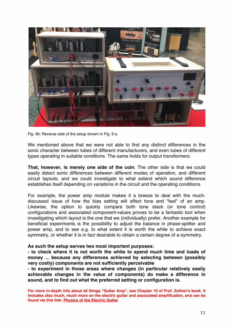
Fig. 9b: Reverse side of the setup shown in Fig. 9 a. We mentioned above that we were not able to find any distinct differences in the sonic character between tubes of different manufacturers, and even tubes of different types operating in suitable conditions. The same holds for output transformers. That, however, is merely one side of the coin. The other side is that we could easily detect sonic differences between different modes of operation, and different circuit layouts, and we could investigate to what extend which sound difference establishes itself depending on variations in the circuit and the operating conditions. For example, the power amp module makes it a breeze to deal with the much-discussed issue of how the bias setting will affect tone and "feel" of an amp. Likewise, the option to quickly compare both tone stack (or tone control) configurations and associated component-values proves to be a fantastic tool when investigating which layout is the one that we (individually) prefer. Another example for beneficial experiments is the possibility to adjust the balance in phase-splitter and power amp, and to see e.g. to what extent it is worth the while to achieve exact symmetry, or whether it is in fact desirable to obtain a certain degree of a-symmetry. As such the setup serves two most important purposes: - to check where it is not worth the while to spend much time and loads of money ... because any differences achieved by selecting between (possibly very costly) components are not sufficiently perceivable - to experiment in those areas where changes (in particular relatively easily achievable changes in the value of components) do make a difference in sound, and to find out what the preferred setting or configuration is. For more in-depth info about all things "Guitar Amp", see Chapter 10 of Prof. Zollner's book. It includes also much, much more on the electric guitar and associated amplification, and can be found via this link: Physics of the Electric Guitar