Embed Size (px)
Citation preview

MODULAR SWITCHGEAR CONTROLGEAR SYSTEM
INSTALLATION OPERATION & MAINTENANCE MANUAL
Pi INSULSAFE MODULAR SYSTEM
TABLE OF CONTENTS
SECTION DESCRIPTION PAGE
A GENERAL INFORMATION 1
A.01 INTRODUCTION 1
A.02 CONSTRUCTION 1
A.03 BUSBAR SUPPORTS 2
A.04 DEMOUNTABLE MODULES 2
A.05 EARTHING 3
A.06 VENTING 3
A.07 NEUTRAL BAR 3
A.08 ARC FAULT CONTAINMENT 3
A.09 INTERLOCKS 3
A.10 RETROFITTING 4
A.11 CONTROL CENTRE TERMINOLOGY 4
A.12 BUSBAR INSULATION 5
A.13 STRUCTURE & FINISH 6
A.14 RATINGS 7
B INSTALLATION INSTRUCTIONS 9
B.01 TIE DOWN OF MCC DURING TRANSIT 9
B.02 GENERAL TIPS ON HANDLING THE MCC 9
B.03 STORAGE 10
B.04 LIFTING 10
B.05 POSITIONING 11
B.06 MOUNTING SURFACE 11
B.07 JOINING AT SHIPPING BREAKS 11
B.08 BOLTING DOWN 12
B.09 PUTTING IN PLACE 13
B.10 INSTALLING CONDUIT AND WIRING 14
B.11 DEMOUNTING THE MODULE 15
B.12 MOUNTING THE MODULE 16
B.13 INSTALLING A NEW UNIT 16
C OPERATING INSTRUCTIONS 17
C.01 DRIVE MODULES 17
C.02 WARNING 17
C.03 OPERATING MECHANISMS AND INTERLOCKS 17
D COMMISIONING 18
D.01 INSPECTION PRIOR TO ENERGIZING 18
E PREVENTIVE MAINTENANCE 20
E.01 GENERAL 20
E.02 PREVENTIVE MAINTENANCE PROGRAM 20
E.03 MECHANICAL CHECKS 20
E.04 CONTACT WEAR AND REPLACEMENT 21

A. GENERAL INFORMATION A.01 INTRODUCTION
The "PI INSULSAFE" has been developed by Plummers industries ‐ Switchboard Division specifically to comply with the requirements of international standards International ElectroTechnical Commission (IEC) 60439 –1 and Australian standard AS/NZS 3439 ‐1 and to deliver significant benefits to engineers, installers and end users. Its space efficient and practicable modular design provides safety, flexibility and economy, making it suitable for most applications.
A.02 CONSTRUCTION
The "PI INSULSAFE" system is manufactured from first grade 2mm zinc seal mild steel sheet. Each component is punched on an AMADA CNC and formed on an NC Bender to ensure high precision. Components then pass through the automated powder coating plant where they are thoroughly cleaned and coated to a dry film thickness of approximately 80 microns. Components fit together to form a strong, uniform line up with guaranteed accuracy. All like parts are fully interchangeable and the system is flexible enough to easily accommodate changes in the lineup at any stage of manufacture as well as extensions and modifications in the field .
Page 1

A. GENERAL INFORMATION
A.03 BUSBAR SUPPORTS
Busbar supports are high‐pressure injection moulded nylon 6 with 25% glass reinforced material which is extremely strong and self‐extinguishing (UL 94 v0).
A.04 DEMOUNTABLE MODULES
Each functional unit up to and including 185KW or 630A is housed in an easily removable, totally segregated drive frame, referred to as a module.
BUS SUPPORTS
MODULE
MODULE IN DEMOUNTED POSITION
Page 2

A. GENERAL INFORMATION
A.05 EARTHING
A full height earth bar is provided within each vertical cable zone. This bar is solidly bonded to the main horizontal earth bar which is at the bottom of the structure and runs its entire length.
Each module is fitted with a wiping earth clip which is designed to come into contact with the structure as soon as the module insertion takes place. A.06 VENTING
Each module is vented on the left‐hand side by means of special louver plates, which provide cooling of internal components by convection and ensure maximum dissipation of gas pressure in the unlikely event of an internal arcing fault. A.07 NEUTRAL BAR
The neutral bar, which runs with the phase bars at the top of the structure, can be 1/3, 1/2 or full size.
There is a neutral bar provided in each vertical busbar chamber adjacent to the phase bars and can be accessed via a 4 pole plug fitted to the draw out module if required A.08 ARC FAULT CONTAINMENT
The Arc Fault containment tests to AS/NZS 3439.1 2002 Annex ZD and have been successfully conducted on the "PI INSULSAFE" covering feeders up to 400A and motor starters up to 150KW. (SEE Section A.14 Ratings)
A.09 INTERLOCKS
All Starter and feeder modules are equipped with a door mounted isolator operating handle and door clutch mechanism affording protection to the operator by preventing access to the interior of the module while the isolator is closed. Warning: It is extremely dangerous to operate any Starter or feeder unless the door is properly closed and secured.
PHASE BUSBAR
NEUTRAL BUSBARS (½ SHOWN)
EARTH
Page 3

A. GENERAL INFORMATION
A.10 RETROFITTING
The PI INSULSAFE may be joined to existing PI INSULSAFE and PI2000 installation using INSULSAFE splice bars and accessories (see Section B.07 Joining at Shipping Breaks –Fish Plates) . Bolting screws for the side covers for both type of MCCs line up for precise interconnection. Module units designed for the INSULSAFE can be mounted in PI2000 using a special module insulator plate . The opposite is not possible. A.11 CONTROL CENTER TERMINOLOGY
LEGEND
1. Top horizontal wireway (cross wiring
zones) 2. Top horizontal wireway cover 3. Horizontal bus zone top cover 4. Cross wiring zone cover 5. Demountable Module pan 6. Demountable Module door 7. Vertical Cable zone door 8. Lifting hole
9. Bottom horizontal wireway (cross wiring access zone)
10. Labyrinth dropper insulator 11. Side Sheet 12. Horizontal bus supports 13. Incomer vertical busbar* 14. Horizontal busbar* 15. Incomer breaker 16. Base (Plinth)
*FULL INSULATION OPTIONAL
Page 4
A. GENERAL INFORMATION
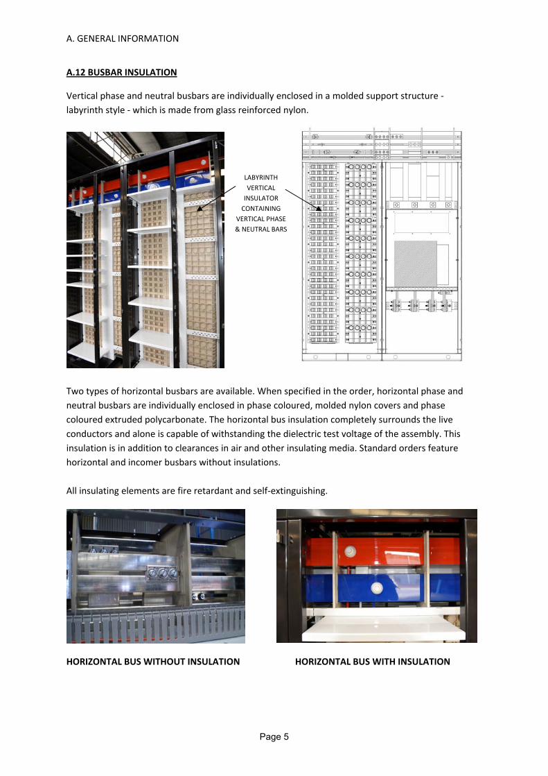
A.12 BUSBAR INSULATION
Vertical phase and neutral busbars are individually enclosed in a molded support structure ‐ labyrinth style ‐ which is made from glass reinforced nylon.
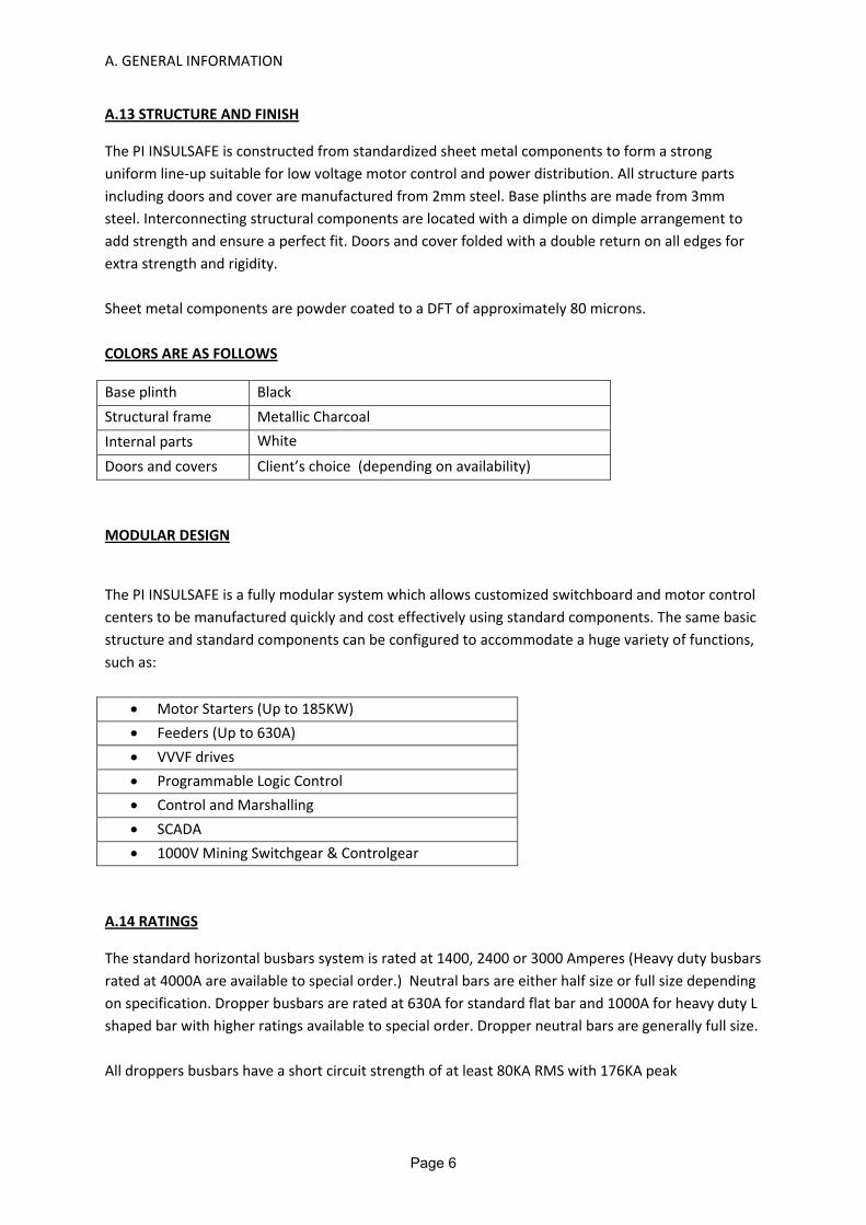
Two types of horizontal busbars are available. When specified in the order, horizontal phase and neutral busbars are individually enclosed in phase coloured, molded nylon covers and phase coloured extruded polycarbonate. The horizontal bus insulation completely surrounds the live conductors and alone is capable of withstanding the dielectric test voltage of the assembly. This insulation is in addition to clearances in air and other insulating media. Standard orders feature horizontal and incomer busbars without insulations. All insulating elements are fire retardant and self‐extinguishing. HORIZONTAL BUS WITHOUT INSULATION HORIZONTAL BUS WITH INSULATION
LABYRINTH VERTICAL INSULATOR CONTAINING
VERTICAL PHASE & NEUTRAL BARS
Page 5
A. GENERAL INFORMATION
A.13 STRUCTURE AND FINISH
The PI INSULSAFE is constructed from standardized sheet metal components to form a strong uniform line‐up suitable for low voltage motor control and power distribution. All structure parts including doors and cover are manufactured from 2mm steel. Base plinths are made from 3mm steel. Interconnecting structural components are located with a dimple on dimple arrangement to add strength and ensure a perfect fit. Doors and cover folded with a double return on all edges for extra strength and rigidity. Sheet metal components are powder coated to a DFT of approximately 80 microns. COLORS ARE AS FOLLOWS
Base plinth Black Structural frame Metallic Charcoal Internal parts White
Doors and covers Client’s choice (depending on availability) MODULAR DESIGN
The PI INSULSAFE is a fully modular system which allows customized switchboard and motor control centers to be manufactured quickly and cost effectively using standard components. The same basic structure and standard components can be configured to accommodate a huge variety of functions, such as:
• Motor Starters (Up to 185KW) • Feeders (Up to 630A) • VVVF drives • Programmable Logic Control • Control and Marshalling • SCADA • 1000V Mining Switchgear & Controlgear
A.14 RATINGS
The standard horizontal busbars system is rated at 1400, 2400 or 3000 Amperes (Heavy duty busbars rated at 4000A are available to special order.) Neutral bars are either half size or full size depending on specification. Dropper busbars are rated at 630A for standard flat bar and 1000A for heavy duty L shaped bar with higher ratings available to special order. Dropper neutral bars are generally full size. All droppers busbars have a short circuit strength of at least 80KA RMS with 176KA peak
Page 6

A. GENERAL INFORMATION
SHORT CIRCUIT STRENGTH
BUSBAR RATING ICW IPK TEST REPORTS Main Busbar 1400A 80KA 1sec 176KA TCA 102247 Main Busbar 2400A 80KA 3sec 176KA TCA 102247 Main Busbar 3000A 80KA 3sec 176KA TCA 102247 Main Busbar 4000A 80KA 3sec 176KA TCA 102240 Main Busbar 1400A 100KA 1sec 220KA TCA 102242 Main Busbar 2400A 100KA 3sec 220KA TCA 102242 Main Busbar 3000A 100KA 3sec 220KA TCA 102242 Main Busbar 4000A 100KA 3sec 220KA TCA 102240 Droppers 630A 80KA 0.2sec 176KA TCA 102240 Droppers 1000A 80KA 1sec 176KA TCA 102240 ARC FAULT CONTAINMENT A representative selection of functional units has been tested to AS/NZS 3439.1 2002 annex ZD to various Prospective faults levels up to 100KA. More than twenty tests were performed and in every case the forces were successfully controlled and contained.
Functional Unit ICP Test report Reference NoSchneider 11KW DOL 50KA TCA 102741 Schneider 37KW DOL 50KA TCA 102741 Schneider 55KW DOL 50KA TCA 102741 Schneider 110KW DOL 50KA TCA 102741 Schneider 11KW DOL 100KA TCA 102741 Schneider 37KW DOL 100KA TCA 102741 Schneider 55KW DOL 100KA TCA 102741 Schneider 110KW DOL 100KA TCA 102741 Schneider 250KW DOL 65KA TCA 102741 Schneider 400a FDR 65KA TCA 102741 NHP 11KW DOL 65KA TCA 102741 NHP 37KW DOL 65KA TCA 102741 NHP 55KW DOL 65KA TCA 102741 NHP 110KW DOL 65KA TCA 102741 NHP 11KW DOL 100KA TCA 102741 NHP 37KW DOL 100KA TCA 102741 NHP 55KW DOL 100KA TCA 102741 NHP 110KW DOL 100KA TCA 102741 Terasaki 250A FDR 80KA TCA 102741 Terasaki 400A FDR 80KA TCA 102741
Page 7

A. GENERAL INFORMATION
INSULSAFE TECHNICAL DATA
Rated voltage 1000VRated frequency 50/60Hz Insulation Power frequency withstand voltage 3.5KV Impulse withstand voltage 12KVNumber of Poles 3 or 4 poles Degrees of Protection Indoor (standard) IP4X Indoor (enhanced) IP53 Outdoor IP56 Internal ≥ IP2XForm of Separation Form 4 (a or b) Rated Current Main Busbars 1400A, 2400A, 3000A, 4000A Droppers (Standard) 630A Droppers (HD) 1000A Branch busbars (Special) ≤ 4000A Rated Short Time Current Main Busbars (Standard) 80KA 3 sec (176KA peak) Main Busbars (HD) 100KA 3 sec (220KA peak) Droppers (Standard) 80KA 0.2 sec (176KA peak) Droppers (HD) 80KA 1 sec (176KA peak) Branch busbars (Special) ≤ 100KA 3 sec (220KA peak)Rated Ambient Temp 40O C
Page 8

B. INSTALLATION INSTRUCTIONS B.01 TIE‐DOWN OF MCC DURING TRANSIT
Figure below shows the correct tie down of the MCC for transit when delivered as a stand‐alone assembly. When delivered as part of a switchroom assembly, MCCs will be braced using angle bars secured to floors and walls of the Switchroom.
After unloading the PI INSULSAFE Motor Control Centre, inspect each section and unit exterior for evidence of damage that may have been incurred during shipment. If there is any indication that the motor control center has been mishandled or shipped on its back or side, remove the draw out units and make a complete inspection of the internal structure, busbars, insulators and unit components for possible hidden damage. Report any damage found to the carrier at once. B.02 GENERAL TIPS ON HANDLING THE MCC
1. Always handle the MCC with care. Always make sure that the MCC is moving slowly to prevent tipping over and shock damage.
2. Handling by overhead crane is preferable but when crane facilities are not available, the motor control center can be positioned with a fork‐lift truck or by using rollers under the shipping skid.
3. Be wary that MCCs are normally top and front heavy. Balance the load carefully and steady, as necessary, while moving. When transporting the MCC using a forklift, use a reliable safety strap.
4. Always put the MCC in an upright position. Never tilt or let the MCC rest on its side. 5. Make sure that the transport means has the capacity to handle the MCCs weight 6. Use Roller pipes or rods for positioning MCC over very short distances and when there is no
incline from one level to another. 7. When using overhead crane, select or adjust the rigging lengths to find the right configuration
that will distribute weight evenly on all four corners of the rig. This will ensure that the MCC remains in the upright position.
Page 9

B. INSTALLATION INSTRUCTIONS
8. The angle between the lifting cables and the vertical must not exceed 45 degrees to avoid excessive stress on any one of the cables.
9. Use lifting cables with steel snaps or safety hooks or shackles whenever possible. Never pass ropes or cables through lifting holes.
10. After putting in place, remove the lifting angles and replace with a suitable hardware to cover the resulting vacant holes.
11. After putting in place, always makes sure that all covers are replaced, doors closed and the Control Cubicles are resting on a level surface.
B.03 STORAGE
If the Control Cubicles cannot be commissioned immediately, it must be kept in a clean and dry location, away from water, dirt, and dust, and safe from mechanical or paint damage. If the storage environment offers any possibility of condensation, install temporary heating, about 150W per section, suspended inside the vertical cable zone. Loose packing, combustible and flammable materials must all be removed before heating. B.04 LIFTING
The "PI INSULSAFE" switchgear assembly is designed to be lifted by its base using lifting bars and sling or fork lifting depending on your requirement. Base lifting points in the form of 38mm diameter holes through the base channel, are provided for this purpose. (Refer to sketch below) the transport stabilization brackets fixed to the roof of the structure are for securing during transport only and should never be used for lifting.
Lifting apparatus and rollers are not provided.
Page 10

B. INSTALLATION INSTRUCTIONS
B.05 POSITIONING When maneuvering the MCC or switchboard into position, the use of crowbars and similar levers should be avoided, since they have the potential to damage the base channel. The preferred method is to move on rollers made from small diameter Pipe or round bar.
B.06 MOUNTING SURFACE
The floor or platform on which the MCC or switchboard is to be mounted should be level and flat so that the weight of the structure is distributed evenly over the entire length of its base channel. If the mounting surface is not flat, then it will be necessary to place packers between the base channel and the mounting surface at regular intervals so that there is no twisting, sagging or bending stress on the MCC or switchboard structure. The temporary transport stabilization brackets can be removed at this point. B.07 JOINING AT SHIPPING BREAKS
Once shipping sections have been maneuvered into position, butted together and aligned they are fastened together using the 8mm bolts and special washers in the joining kit provided. Each kit includes 4 bolts and 8 washers. Fixing holes are pre‐ punched in the side sheets, top and bottom at the front and top and bottom at the rear. The horizontal busbars are joined using the fishplates and special hardware in the joining kit provided. The main earth bar at the bottom of the structure is joined with a simple fishplate also provided in the kit. 12mm high tensile bolts used on horizontal busbar connections should be tightened to a torque of 60nm. 10mm high tensile bolts used on earth bar connections should be tightened to a torque of 40nm. Where Bellville washers are used it is recommended to take the bolt up to tight and back it off a quarter of a turn. If the fully insulated MCC is used, care must be taken to ensure the joint covers (provided) are used in an appropriate manner.
FIGURE B.07A
Page 11

B. INSTALLATION INSTRUCTIONS
FISH PLATES
B.08 BOLTING DOWN
When the shipping sections have been joined together correctly, the MCC or switchboard must be securely fastened to the floor at each designated fixing down point using bolts with a minimum diameter of 10mm. Fixing down holes are pre‐ punched in the base channel and drilling access is provided by a pre‐punched drill clearance hole positioned at the top of the base channel, directly above each fixing hole.
FIGURE B.07A
Page 12

B. INSTALLATION INSTRUCTIONS
B.09 PUTTING‐IN‐PLACE
1. Prior to any installation work, check all drawings provided by Plummers Industries and specifications, As‐Built drawings and specifications applicable to the contract. Pay special attention to arrangement of elements with respect to planned conduiting, cabling and ducting. Check that all grounding requirements are properly satisfied.
2. The Motor Control Centre must be securely positioned and anchored on a smooth level surface. The foundation must be true and level, or that shims that are capable of supporting the structure are provided to ensure flatness of the surface. In some cases, levelled channel sills under both the front and rear of the control centre are necessary to provide a flat surface. These sills can be either mounted on top of the floor or grouted in the concrete floor. The sills are then drilled with holes that coincide with the bolting down holes of the Control Centre. Make sure that the sills are properly grounded on its entire length.
3. After bolting down and wiring, cabling and necessary adjustments are complete, close all modules units, wireway doors and covers. .
4. In damp environments, protect the MCC from moisture accumulation or water entering the enclosure.
5. The standard Pi Insulsafe is designed for a working environment where the ambient temperature is 40 degrees centigrade, there are no fumes dust, explosive fumes, vapours, dripping or standing water, abnormal vibration, and shock or tilting.
6. Conduit stubs can be located in the area described by a shaded region in the MCC base drawing. The shaded area represents unobstructed area of the base.
7. When two or more shipping frames are to be bolted together, or additional tiers added to existing installations, the following are to be planned properly: splicing of control wires and power cables, horizontal bus, ground bus, neutral bus. Unscrew and remove the side covers from adjacent vertical sections to be joined. Fish plates and accessories for the horizontal bus, Neutral Bus and Ground bus will be shipped with MCC. Refer to Figure B.07B
8. The Insulsafe Fish Plate system provides the most convenient access to the bolts, and obviates the removal of the horizontal bus barriers in any of the structures. If the existing bus be oxidized, sand lightly with a new aluminium oxide paper. Important – never use emery cloth or any abrasives containing ferrous material.
9. Move the additional section in place, aligning the upright structural channels and bottom channels. Remove the vertical wireway cover to gain access to two screws located at the top and bottom of the section. Alignment of the section with floor sills and foundation provisions will be facilitated by the dimple to dimple alignment system. Four (4) bolt holes are available to secure the newly aligned sections.
10. Fix the sections to the floor or sills. Secure the horizontal bus splice plates to the bus, and ground plates at the bottom, torqueing all bus splice bolts to 60NM. Replace all unit, bus barriers, and doors.
Page 13

B. INSTALLATION INSTRUCTIONS
11. Each splice plate kit consists of short Pieces of bus bar shipped with, four bolts per phase, and appropriate quantities of related hardware. The end splice plate employs a cone shaped but (provided) which bites into the busbar preventing rotation as the bolt is tightened.
B.10 INSTALLING CONDUIT AND WIRING
1. When planning for module power cabling, allow for sufficient slack so that the unit can be withdrawn to the detent position for maintenance. Conduits are to be installed such as to prevent liquid from entering and accumulating in the enclosure or in the conduit itself. Avoid sags in the conduit. Conduits are to be positioned only in areas designated for conduiting (refer to General Arrangement drawings for details) to avoid cable interference with structural members and live bus.
2. If more than one conduit is necessary to bring the wires from a common source to a common load, each conduit must carry same phase conductors and same quantity. If the phase conductors are not distributed evenly, eddy currents will raise the temperature of the steel between conduits.
3. Conductors inside the MCC must be arranged such as to avoid physical damage and overheating. Secure or brace incoming power cables to withstand dynamic forces which will act to separate or weld the conductors under short circuit conditions. Cable ties must be used in both horizontal and vertical wire ways to support the load and interconnection wire. For external field wiring, use a shielded communications cable inside of flexible metal conduit to protect very low voltage signals transmitted to or from a computer or programmable controller.
4. Use care in stripping insulation to avoid nicking or ringing the metal. All fields wiring to control units should be made in accordance with the wiring drawings that are furnished with the control centre. Load and control wiring can be brought in through the upper and/or lower horizontal wire ways.
5. Field wirings are, as a standard, terminated in the vertical cable zone via terminal blocks.
6. The phase sequence of the power circuit load terminals (Left to right, back to front, top‐to‐bottom: R, Y, B) in units mounted on the rear side of the MCC is the same to that of the load terminals in units mounted on the front side of a back‐to‐back MCC.
Page 14
B. INSTALLATION INSTRUCTIONS
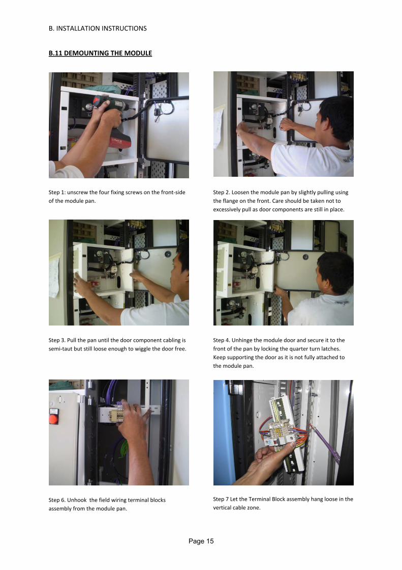
B.11 DEMOUNTING THE MODULE
Step 1: unscrew the four fixing screws on the front‐side of the module pan.
Step 2. Loosen the module pan by slightly pulling using the flange on the front. Care should be taken not to excessively pull as door components are still in place.
Step 3. Pull the pan until the door component cabling is semi‐taut but still loose enough to wiggle the door free.
Step 4. Unhinge the module door and secure it to the front of the pan by locking the quarter turn latches. Keep supporting the door as it is not fully attached to the module pan.
Step 6. Unhook the field wiring terminal blocks assembly from the module pan.
Step 7 Let the Terminal Block assembly hang loose in the vertical cable zone.
Page 15

B. INSTALLATION INSTRUCTIONS
Step 8. Check if are there are any more obstructions. Keep an eye on the loose TB Assembly while doing step 9.
Step 9. Continue pulling until the entire unit is fully demounted and the TB assembly clear of the MCC frame.
B.12 MOUNTING THE MODULE
To mount the existing module, simply follow above procedures in reverse.
B.13 INSTALLING A NEW UNIT
Installing new units is as easy as removing the blank door, inserting the new module unit, bolting the screws on the front‐side, fixing the new door and splicing the interconnecting wires and cables. New units include a module pan (all the components already installed if factory ordered), a unit door with male part of the hinge, screws for the pan and other hardwares that comes with the order (Terminal block for field wiring, TB labelling, etc.). Note the following sequence of operations for installation.
1. Remove the existing blank door.
2. Install the new module pan making sure there are no obstructions along the path.
3. Fix the thread forming screw on four locations on the front‐sides of the pan.
4. Install the new door
5. Screw the new terminal block assembly.
Page 16

C. OPERATING INSTRUCTIONS
C.01 DRIVE MODULES
Each drive module and feeder module is equipped with an isolator, which is operated by a door‐mounted handle via a door clutch mechanism. This arrangement prevents the module door being opened while the isolator is closed.
The procedure for opening the module door is as follows: 1. Move the isolator operating handle to the "off" position. 2. Release 1/4 turns locks securing the module door. 3. Hold the isolator operating handle in the "off" position (counterclockwise rotation) to
release the interlock mechanism, and swing the door outwards, left to right. C.02 WARNING!
It would be extremely hazardous to attempt to operate a Starter or feeder when the module door is open. The module units of the Insulsafe Motor Control Centre can only be operated safely when the module door is properly closed and secured.
C.03 OPERATING MECHANISMS AND INTERLOCKS
Dangerous situations could arise when any part of the MCC becomes defective. Ensure that all parts are working properly. Special attention should be given to parts that provide insulation (e.g. safety covers, barriers and shrouding) and that they remain secured to their place.
The interlock against opening the module door while the module is energized is provided for personnel and equipment protection. However, for this class of equipment, authorized personnel can defeat the interlock mechanism. For procedure on how to defeat the handle interlock, please refer to a separate product leaflet provided in the order’s Installation, Operation and Maintenance Manual (IOM).
Page 17

D. COMMISSIONING
D.01 INSPECTION PRIOR TO ENERGIZING
1. Prior to energizing the Motor Control Centre, thoroughly inspect to be sure all foreign materials such as tools, scraps of wire and other debris are removed from all units and the structure. Remove any accumulation of dust and dirt with and vacuum cleaner. (Use of blower is not recommended as this will merely rearrange the debris).
2. All circuit connections are tightened at time of assembly using controlled torques. However, transit conditions may loosen some of these connections. Spot check at least 10% of the total connections for tightness. Should this spot‐check reveal any loose connections, check all connection points. To be rechecked are the bus hardwares, circuit breaker connections, switch terminals, contactor and relay terminals and terminal blocks. Always check incomer line connections.
3. Remove all temporary shipment accessories from all components (e.g. desiccants, movement blocks of Protective relays, etc.) and in the MCC interior.
4. Make sure the enclosure has not suffered any damage as to reduce phase polarity or phase to ground clearances.
5. Check that all wiring diagrams are in agreement with approved drawings and make sure cabling from the starters or feeder units are connected to its intended loads.
6. Check that all field wirings and normally live buses and conductors are clear of unwanted contacts and physically secured to resist effects of faults currents.
7. Make sure all necessary grounding connections are provided and properly connected.
8. Ensure all components are without damage. Arrange to replace all defective components prior to energizing.
9. Physically check switches, circuit breakers, and other operating mechanisms for alignment and proper operation.
10. Test any ground fault protection systems that were supplied with the MCC.
11. Set adjustable current and voltage trip mechanisms to final values.
12. Make no attempt to operate a current transformer with its secondary circuit open. Make sure CTs are connected to load or a properly connected secondary shorting bar.
13. Make sure that all parts removed during wiring and installations have been replaced to avoid possible injury or damage to equipment during energization.
14. Insulation resistance test must be conducted to ensure there are no unintentional short circuits and grounds. Check with your local codes, international standards, and/or contract specifications for procedures on this test.
Page 18

D. COMMISSIONING
15. Make sure all frames are aligned, covers and doors are closed and no wires or cables are pinched against other parts of the MCC.
16. All switches, circuit breakers and fuses must be turned off prior to energizing of the incoming supply.
Page 19
E. PREVENTIVE MAINTENANCE E.01 GENERAL
Maintenance of electrical equipment has two basic purposes:
1. Keep the conductive materials conductive 2. Keep insulated materials insulated. Annual maintenance is recommended ‐ and more frequently if conditions are harsh in terms of dust, vibration, temperature, humidity and severity of operation. Preventive maintenance procedures should include (but not be limited to): a) Routine tests in accordance with AS 3439 ‐1 b) Ductor tests of all busbar connections c) Removal of all modules to inspect for evidence of overheating of main incoming
Plug contacts As an alternative to b) and c) above, we recommend that a thermographic survey be conducted annually, supplemented by more frequent inspections using a hand held infrared scanner. Note: It is generally not recommended to check busbar joints by performing a bolt check, since over tightening could cause bolts to fatigue. E.02 PREVENTIVE MAINTENANCE PROGRAM
Plummers recommend outlining a program to periodically inspect the equipment. This program should start from the time the equipment is installed. During installation, all manufacturer’s data should be studied and then kept for future reference. Maintenance checks should be regular, or as frequently as the product maintenance guide specifies (which might denote frequency for both normal and harsh conditions). A checklist is suggested to establish and facilitate inspection points and standardize data. A logbook is also desirable to record incidents and repairs while the equipment is in service. A supply of spares should also be acquired and properly stored for quick deployment. Ensure to comply with local, state and national regulations, as well as safety practices. When servicing and adjusting the electrical equipment, refer to the applicable drawings covering the specific motor control centre (MCC) and any other related interconnection drawings.
E.03 MECHANICAL CHECKS
Caution: In maintaining the control components, all power to these components must be disconnected by turning off the branch circuit switch and withdrawing the unit to its demounted position.
Warning: When the module unit is fully inserted, the power and control circuits will be energized. Padlocking of the handle in the OFF position to prevent movement to ON position is available.
1. All mechanical interlocks should be checked for integrity and functional operation.
Page 20

E. PREVENTIVE MAINTENANCE
2. Clean and tighten joints and ensure they are free from contaminants.
3. All foreign materials and debris must be removed from the MCC. (a vacuum cleaner instead of a blower is essential as blowers merely rearrange the contaminants) Control equipment must be kept clean and dry. Do not use liquid cleaner. Removing foreign materials from the outside top and inside bottom will ensure that future examinations will reveal any materials that have fallen off or dropped onto the MCC. Should liquid spreads be found, inspect for source and rectify by sealing possible openings, adding space heaters, or other actions as appropriate.
4. Check all connection tightness. Watch out for signs of joint overheats, carbonized insulation, stained terminals, etc. Physically clean to a shiny finish (but don’t use emery or other ferrous abrasives). Replace disfigured or discoloured joints or terminations. Inspect for cause of stains and discoloration and rectify. Care should be taken with aluminium wire connections. To aluminium wires, use crimp type lugs. If screw type lugs (of the cu/al variety) are used with aluminium wire, joints should be inspected for every 200 operations of the device.
5. Wires and cables should be clear of steel parts to avoid chaffing especially during vibrations. This could lead to insulation failures. All temporary wirings (CT shorts, temporary contact shorts, temporary power supply leads, etc) should be removed. Otherwise secure these wires and mark as appropriate in the as‐Built wiring diagrams. Intended movements of mechanical parts (e.g. contactor armature, TOl Reset buttons, Pushbuttons, switches, swing fuse blocks, etc), should be unimpeded.
6. Record changes and observation notes into a log book before putting the MCC into service. Never remove existing labels or nameplates. Replace any that have been damaged.
E.04 CONTACT WEAR AND REPLACEMENT
1. Mechanical and electrical wear affects magnetic contactors during operation. For the most part, the mechanical wear is insignificant but the erosion due to electrical wear will be much greater. Each time the magnetic contactor is switched off, an arc is generated which vaporizes the contacting surface of the contactor. An examination of the contact surfaces and measurement of contact overtravel will provide useful information to get the maximum contact life of the contactor. Consult OEM manufacturer’s guidelines and how to determine acceptable conditions and how to measure overtravel .
2. All separate auxiliary supplies must be disconnected as well. When a temporary auxiliary supply is used during maintenance, care should be taken to prevent feedback of dangerous voltage through the Control Potential Transformer. Be aware also that Power Factor correction capacitors may be charged and can generate potentially damaging voltages. Discharge these capacitors before attempting to work on any part of the Motor Control Centre.
Page 21
10BeW(T)(F)ad
PI Insulsafeproperly trainential featureations or com
e operation, oh local, stateot connected
REGULA
0 Wheeler Selmont
WA 6104 ) (61) 08 92) (61) 08 94dmin@plum
neral ManagHN PLUMME
es ManagerAN REEVES (
ctrical ManaRRY UNDER
C
e Motor Contned tradesmes of the Mombinations oor maintenan
e and nationad to a source
AR OFFICE
Street
277 7255 478 300 mmers.com.
ger ER (0419 46
r (0419 465 3
ager RWOOD (04
CONTA
trol Centre ismen. Although
tor Control Cof the equipmnce. Care mual regulatione with higher
E HOURS:
.au
AFTER
65 365)
369)
488 104 420
ACT DE
s intended toh attempts hCentre, thesement, its stoust be taken
ns as well as r short circui
06:30 – 1
75 WSumQue(T) ((F) (adm
R OFFICE H
0)
ManaPETER
ETAILS
o be installedhave been me instruction
orage, delivern to ensure th safety practit capacity.
15:00 MON
Wolston Romner Park eensland 4061) 07 371561) 07 3715
min@plumm
HOURS
ager R FILLER (04
S
d, operated aade to descr
ns do not purry, installatiohat installatitices and tha
NDAY TO
ad
074 5 8277 5 8288 mers.com.au
417 017 522
and maintainribe the rport to coveion, check ouions comply at the equipm
FRIDAY
u
2)
ned
er all ut, ment