Embed Size (px)
Citation preview

Modular I/O System
PROFIBUS DPV1
750-333 / 750-833
Manual
Technical description,installation andconfiguration
Supplement for the Manual 750-131Version 2001-02-27

ii General
D R A F T WAGO-I/O-SYSTEM 7502001-02-27 PROFIBUS
Copyright 2001 by WAGO Kontakttechnik GmbHAll rights reserved.
WAGO Kontakttechnik GmbHHansastraße 27D-32423 Minden
Phone: +49 (0) 571/8 87 0Fax: +49 (0) 571/8 87 1 69
E-Mail: [email protected]
Web: http://www.wago.com
Technical SupportPhone: +49 (0) 571/8 87 5 55Fax: +49 (0) 571/8 87 4 30
E-Mail: [email protected]
Every conceivable measure has been taken to ensure the correctness and com-pleteness of this documentation. However, as errors can never be fully ex-cluded we would appreciate any information or ideas at any time.
We wish to point out that the software and hardware terms as well as thetrademarks of companies used and/or mentioned in the present manual aregenerally trademark or patent protected.

Table of Contents iii
WAGO-I/O-SYSTEM 750 D R A F TPROFIBUS 2001-02-27
TABLE OF CONTENTS
1 Important comments..................................................................................11.1 Legal principles ......................................................................................11.2 Scope ......................................................................................................21.3 Symbols..................................................................................................21.4 Font conventions ....................................................................................31.5 Number notation.....................................................................................31.6 Abbreviation...........................................................................................4
2 WAGO-I/O-SYSTEM 750.........................................................................52.1 System Description ................................................................................52.2 Installation..............................................................................................82.3 Electrical Installation............................................................................112.4 Power supply........................................................................................132.5 Manufacturing Number ........................................................................162.6 Technical Data......................................................................................17
3 Fieldbus coupler / controller ...................................................................193.1 Fieldbus coupler 750-333.....................................................................193.2 Fieldbus Controller 750-833 ................................................................74
4 I/O Modules ............................................................................................1324.1 Digital Input Modules ........................................................................1324.2 Digital Output Modules......................................................................1324.3 Analog Input Modules........................................................................1324.4 Analog Output Modules .....................................................................1324.5 ............................................................................................................132
5 PROFIBUS..............................................................................................1335.1 Description .........................................................................................1335.2 Topology ............................................................................................1335.3 Wiring ................................................................................................133
6 Configuration example ..........................................................................1356.1 NETCON............................................................................................1356.2 Step 7..................................................................................................1356.3 COM Profibus ....................................................................................135

iv Table of Contents
D R A F T WAGO-I/O-SYSTEM 7502001-02-27 PROFIBUS
7 Explosive Environments ........................................................................1367.1 Foreword ............................................................................................1367.2 Protective measures............................................................................1367.3 Classification meeting CENELEC / IEC............................................1367.4 Classifications meeting the NEC........................................................1417.5 Identification acc. to CENELEC, IEC and ATEX 100a.....................1437.6 Identification acc. to NEC 500 ...........................................................1447.7 Installation regulations .......................................................................145
8 Glossary...................................................................................................147
9 Literature list ..........................................................................................149
10 Index ........................................................................................................150

Important comments 1
WAGO-I/O-SYSTEM 750 D R A F TPROFIBUS 2001-02-27
1 Important commentsTo ensure fast installation and start-up of the units described in this manual,we strongly recommend that the following information and explanation iscarefully read and adhered to.
1.1 Legal principles
1.1.1 Copyright
This manual is copyrighted, together with all figures and illustrations con-tained therein. Any use of this manual which infringes the copyright provisionsstipulated herein, is not permitted. Reproduction, translation and electronicand photo-technical archiving and amendments require the written consent ofWAGO Kontakttechnik GmbH. Non-observance will entail the right of claimsfor damages.
1.1.2 Personnel qualification
The use of the product detailed in this manual is exclusively geared to special-ists having qualifications in PLC programming, electrical specialists or per-sons instructed by electrical specialists who are also familiar with the validstandards. WAGO Kontakttechnik GmbH declines all liability resulting fromimproper action and damage to WAGO products and third party products dueto non-observance of the information contained in this manual.
1.1.3 Intended use
For each individual application, the components supplied are to work with adedicated hardware and software configuration. Modifications are only admit-ted within the framework of the possibilities documented in the manuals. Allother changes to the hardware and/or software and the non-conforming use ofthe components entail the exclusion of liability on part of WAGO Kon-takttechnik GmbH.
Please direct any requirements pertaining to a modified and/or new hardwareor software configuration directly to WAGO Kontakttechnik GmbH.

2 Important comments
D R A F T WAGO-I/O-SYSTEM 7502001-02-27 PROFIBUS
1.2 ScopeThis manual describes the field bus independent WAGO-I/O-SYSTEM 750with the fieldbus coupler for PROFIBUS.
Item-No. Components
750-333 PROFIBUS DP/DPV1 12 MBd
750-833 Contr. PROFIBUS DP/DPV1 12 MBd
750-xxx I/O Modules
1.3 Symbols
DangerAlways observe this information to protect persons from injury.
WarningAlways observe this information to prevent damage to the device.
AttentionMarginal conditions must always be observed to ensure smooth operation.
ESD (Electrostatic Discharge)Warning of damage to the components by electrostatic discharge. Observe theprecautionary measure for handling components at risk.
NoteRoutines or advice for efficient use of the device and software optimisation.
iMore informationReferences to additional literature, manuals, data sheets and INTERNETpages

Important comments 3
WAGO-I/O-SYSTEM 750 D R A F TPROFIBUS 2001-02-27
1.4 Font conventionsItalic Names of path and files are marked italic
e. g.: C:\programs\WAGO-IO-CHECK
Italic Menu items are marked as bold italice. g.: Save
\ A backslash between two names marks a sequence ofmenu itemsz. B.: File\New
END Press bottons are marked as bold with small capitalse. g.: ENTER
< > Keys are marked bold within angle bracketse. g.: <F5>
Courier Program code are printed with the font Courier.e. g.: END_VAR
1.5 Number notation
Number Code Example NoteDecimal 100 normal notation
Hexadecimal 0x64 C notation
Binary '100''0110.0100'
Within ',Nibble separated with dots

4 Important comments
D R A F T WAGO-I/O-SYSTEM 7502001-02-27 PROFIBUS
1.6 AbbreviationDI Digital Input
DO Digital Output
I/O Input/Output
ID Identifier
PFC Programmable Fieldbus Controller
PFC-PI Programmable Fieldbus Controller - Process Images
PFC-RTS Programmable Fieldbus Controller - Runtime system
PI Process Images
PLC Programmable Logic Control
AO Analog Output Module
AI Analog Input Module
SM Special Module

WAGO-I/O-SYSTEM 750 5System Description
WAGO-I/O-SYSTEM 750 D R A F TPROFIBUS 2001-02-27
2 WAGO-I/O-SYSTEM 7502.1 System Description
2.1.1 General
The WAGO-I/O-SYSTEM 750 consists of various components which are ca-pable of providing modular and application specific fieldbus nodes for variousfieldbusses.
A fieldbus node (short: Node) consists in principle of a fieldbus coupler (short:Coupler) ) or Programmable Fieldbus Controller (short: Controller) ) (1) at thefront end, a number of special I/O modules (2) and a End Module (3) which isplaced at the other end.
750-630 750-650
75
0-3
33
PROFIBUS
RUN
BF
DIA
BUS
I/O
1 2 3
750-400 750-410 750-403 750-454 750-467 750-461750-612 750-512 750-512 750-513 750-610
max. 6,3 A
250 V
750-552750-550 750-600
0
5
9
87 6 4
321
X 10
X 10
5
9
87 6 4
321
RTS CTS
TxD RxD
MM
SS
+ +
CL-CL+
D+ D-
M M
S S
+ +
S S
+ +
N NN N
L LL L
S S
MM
SS
M M
S S
++++++++
0V24V
16
15
14
13 23
24
01 02 04 05
06
07
08
09 10 11 1203 17
18
19
20
21 22
25
26
27
28
29 30 31 32
L L
N N
Fig. 2-1: Setting up a fieldbus node for PROFIBUS g01x101x

6 WAGO-I/O-SYSTEM 750System Description
D R A F T WAGO-I/O-SYSTEM 7502001-02-27 PROFIBUS
2.1.2 Coupler/Controller (1)
The Coupler/Controller forms the link between the fieldbus and the field de-vices with their I/O functions. All control functions required for the faultlessoperation of the I/O functions are carried out by the Coupler/Controller. Theconnection to different fieldbus systems is established by each of the corre-sponding Coupler/Controller, e.g. for PROFIBUS, INTERBUS, CAN,MODBUS etc. In this way a change of the fieldbus system is possible.
The programmable fieldbus controller 750-833 combines the PROFIBUS DPfunctionality of the fieldbus coupler 750-333 with the functionality of a Pro-grammable Logic Control (PLC). Programming of the application is done withWAGO-I/O-PRO in accordance with IEC 61131-3, covering all 5 program-ming languages. The programmer can access all fieldbus and I/O data.
Characteristics and use of the Controllers:
• The use of decentralized control can better support a PLC or PC
• Signal pre-processing reduces fieldbus transmissions
• Complex applications can be divided into multiple tasks
• Tasks can be prioritized
• Peripheral equipment can be controlled directly, resulting in faster systemresponse times
• Programmable response in the event of a fieldbus failure
• Simple, self-sufficient control

WAGO-I/O-SYSTEM 750 7System Description
WAGO-I/O-SYSTEM 750 D R A F TPROFIBUS 2001-02-27
2.1.3 I/O Modules (2)
In the I/O modules, the incoming process data is converted. Corresponding tothe different requirements, special I/O modules are available for a variety offunctions. There are digital and analog inputs and outputs and modules forspecial functions (Counter modules, Terminal blocks for encoder and resolversand communication modules).
2.1.4 End Module (3)
A End Module is needed for faultless operation of the node. The terminationmodule is always placed as the last module in order to obtain a termination ofthe fieldbus node. This module has no I/O function.

8 WAGO-I/O-SYSTEM 750Installation
D R A F T WAGO-I/O-SYSTEM 7502001-02-27 PROFIBUS
2.2 Installation
2.2.1 Safty notes
ESD (Electrostatic Discharge)The modules are equipped with electronic components which may be de-stroyed by electrostatic discharge.When handling the modules, ensure that theenvironment (persons, workplace and packing) is well grounded. Avoidtouching conductive components, e.g. gold contacts.
AttentionSwitch off the system prior to working on bus modules!
2.2.2 Mechanical Installation
All system components can be snapped directly on a carrier rail in accordancewith the European standard EN 50022 (DIN 35).
AttentionEnsure that the carrier rail is fastened with countersunk head screws or blindrivets as the snap-on foot of the I/O components extends onto the carrier rail.
The installation is simple and space saving. All modules have the same shapeto minimize the project commitment.
The reliable positioning and connection of the coupler and the individual I/Omodules is made using a tongue and groove system. Due to the automaticlocking, the individual components are securely seated on the rail after in-stalling.
WAGO-I/O-SYSTEM 750 9Installation
WAGO-I/O-SYSTEM 750 D R A F TPROFIBUS 2001-02-27
To secure the coupler/controller against moving sideways, fix it with the or-ange colored locking disc on the carrier rail. To fix, insert a screwdriver intothe top groove of the locking disc and press.
To pull out the fieldbus coupler, release the locking disc by pressing on thebottom groove with a screwdriver and then pulling the orange colored un-locking lug.
Entriegelungs-lasche
fixierenlösen
Fig. 2-2: Coupler/Controller and unlocking lug g012201d
It is also possible to release an individual I/O module from the unit by pullingan unlocking lug.
Fig. 2-3: Releasing a I/O Module p0xxx01x
DangerEnsure that an interruption of the PE will not result in a condition whichcould endanger a person or equipment!

10 WAGO-I/O-SYSTEM 750Installation
D R A F T WAGO-I/O-SYSTEM 7502001-02-27 PROFIBUS
Self-cleaning power jumper contacts conduct the supply voltage for the fieldside. They are located on either side of the modules. The female contacts onthe right-hand side of the fieldbus coupler and the bus modules are designed asspring contacts to protect against accidental contact. Male contacts are locatedon the left-hand side of the bus modules.
Pos. 1
Pos. 2
Fig. 2-4: Power Jumper Contacts g01xx00d
DangerThe power contacts are sharp-edged. Handle the module carefully to preventinjury.
AttentionPlease take into consideration that some bus modules have no or only somepower jumper contacts. The design of some modules does not physically al-low assembly them in rows as the grooves for the male contacts are closed atthe top.
The data contacts are designed as self-cleaning gold spring contacts whichautomatically produce a secure connection.
Fig. 2-5: Data contacts p0xxx07x
WarningDo not connect the I/O module to gold spring contacts in order to avoid soil-ing or scratches!

WAGO-I/O-SYSTEM 750 11Electrical Installation
WAGO-I/O-SYSTEM 750 D R A F TPROFIBUS 2001-02-27
2.3 Electrical Installation
2.3.1 Wire Connection
Conductors with a cross section of 0.08 to 2.5 mm² (AWG 28-12) can be con-nected using a CAGE CLAMP connection to achieve a vibration resistant,fast and maintenance free connection. To actuate CAGE CLAMP enter anactuation tool in the opening above the connection. Following this, enter theconductor in the corresponding opening. The conductor is clamped securelywith the removal of the actuation tool.
Fig. 2-6: Inserting conductor end p0xxx06x
The clamping force adjusts automatically to the cross section. The full surfaceof the CAGE CLAMP pressure is applied against the conductor withoutdamaging it. Conductor deformation is compensated for and self-loosening isavoided. The transition point between the conductor and the CAGE CLAMP
is protected against corrosive influences. The connection can be made quicklyand is also maintenance free, saving the costs for a periodic checking of termi-nal connections.
Two carrier rail contacts responsible for the electrical contact between thegrounded carrier rail and the controller, are fitted underneath the cou-pler/controller.
AttentionEnsure a perfect contact point between carrier rail contacts and carrier rail.The carrier rail must be grounded.

12 WAGO-I/O-SYSTEM 750Electrical Installation
D R A F T WAGO-I/O-SYSTEM 7502001-02-27 PROFIBUS
2.3.2 Change fuse
Some Power supply modules of the WAGO-I/O-SYSTEM 750 are equippedwith a fuse holder. To isolate the modules to the right of the power supply, thefuse can be removed from the fuse holder. For this insert a srew driver into oneof the slits available on each side and lift the holder
Fig. 2-7: Removing the fuse holder p0xxx05x
The fuses can be removed from or inserted into the holder with the fuse holdercover and push the fuse holder pushed back into the original position.
Fig. 2-8: Opening the fuse holder p0xxx03x
Fig. 2-9: Change fuse p0xxx04x

WAGO-I/O-SYSTEM 750 13Power supply
WAGO-I/O-SYSTEM 750 D R A F TPROFIBUS 2001-02-27
2.4 Power supply
750-630 750-650750-400 750-410 750-403 750-454 750-467 750-461750-612 750-512 750-512 750-513 750-610 750-552750-550 750-600750-616
~
24V 24V 24V230V
1
2
Fig. 2-10: Power supply g01xx02x
1 Power supply System2 Power supply Field-side
The power supply on the field side is electrically isolated from the system sup-ply. In this manner sensors and actuators can be supplied and fused by a sepa-rate voltage source.
If a non-regulated power supply is used for the coupler/controller electronics24 V voltage supply , it must be filtered through a capacitor (200 µF per 1 Aload current). To this effect a back-up capacitor module (Order-No. 288-824)was developed for the WAGO-I/O-SYSTEM. This module serves to regulate anoisy 24 V DC voltage supply, to keep the ripple voltage within specified lim-its. The cause for these fluctuations could be a voltage interruption on the pri-mary side, a secondary side overload or the switching of non quenched in-ductance or capacitance.
WarningThe supply modules + and which are permanently integrated on the buscou-plers, can be supplied with 24 V DC only.120 V AC and 230 V AC can only be supplied via modules 750-609, 750-611and 750-612!
WarningThe ground (earth) field side contact should be disconnected when testing theisolation. Otherwise the results could be wrong or the module could be de-stroyed.

14 WAGO-I/O-SYSTEM 750Power supply
D R A F T WAGO-I/O-SYSTEM 7502001-02-27 PROFIBUS
2.4.1 System supply voltage
The system supply voltage (24 V DC) is filtered with a voltage regulator be-fore powering the coupler electronics as well as to the internal bus. Electricalisolation from the external fieldbus system depends on the type of Cou-pler/Controller.
The internal bus includes the internal communication between the cou-pler/controller and the bus modules as well as the power supply for the busmodules. The power supply is limited to a maximum value. This value de-pends on the type of Coupler/Controller. If the sum of the internal power con-sumption of all bus modules exceeds this value, it is necessary to add addi-tional internal system supply modules (Order-No. 750-613).
The control electronics in the bus modules are powered by snap-fit mountingthe bus modules using the internal bus contacts. A reliable contact is assuredby the gold plated, self cleaning slide contacts. The removal of a bus modulewill cause an interruption in communication to the following bus modules.The coupler/controller identifies the interruption point and displays a corre-sponding fault message.
WarningRemoving or inserting the I/O modules with the voltage applied can lead toundefined conditions. For this reason only undertake work on the I/O moduleswhen isolated from the power supply!

WAGO-I/O-SYSTEM 750 15Power supply
WAGO-I/O-SYSTEM 750 D R A F TPROFIBUS 2001-02-27
2.4.2 Supply Voltage Field Side
The voltage is automatically supplied when the I/O modules are snapped to-gether. Self-cleaning power jumper contacts (P.J.C.s) ensure safe connections.The current capacity of the power contacts is 10 A max.
The PE contact is a preceding ground (earth) contact corresponding to thestandards which can be used as a protective earth. The contact has a leakagecapacity of 125 A.
WarningProduce a low impedance connection from the carrier rail to the PE contactpoint in the switch cabinet.
AttentionDepending on the I/O function, some modules do not have P.J.C.s. It is im-portant to note this when assembling a node. Many modules require field sidepower, many do not. Please review the circuit diagrams of the individual mod-ules. An additional power supply module may be necessary.Refer to the individual terminal/module data sheets!
When adding a power supply module, the field supply is always interrupted atthe power contacts. From this point a new power supply is made, which canalso include a potential change. This feature guarantees a high degree of sys-tem flexibility.

16 WAGO-I/O-SYSTEM 750Manufacturing Number
D R A F T WAGO-I/O-SYSTEM 7502001-02-27 PROFIBUS
2.5 Manufacturing NumberThe production number is part of the lateral marking on the component. Thenumber contains the production date, the software version and the hardware ofthe component.
Hansastr. 27D-32423 Minden
ITEM-NO.:750-400
2DI 24V DC 3.0ms
0.08-2.5mm2
0V 24V DI1
Di2
PATENTS PENDINGII 3 GKEMA 01ATEX1024 XEEx nA II T4
CL
ID
IVG
rp.
AB
CD
opte
mp
code
T4A
24V
DC
AW
G28
-14
55°C
max
ambi
ent
LIS
TE
D22
ZA
AN
D22
XM
24
24
6
09
01
--0
2--
--0
3
9 0 1 - - 0 20 0
Manufacturing Number
Calendarweek
Year Softwareversion
Hardwareversion
Fig. 2-11: Manufacturing Number g01xx09e
The remaining digits and characters represent internal information byWAGO Kontakttechnik GmbH.
As of calendar week 09/2001, the production number is additionally printed onthe cover of the configuration and programming interface of the fieldbus cou-pler or controller.

WAGO-I/O-SYSTEM 750 17Technical Data
WAGO-I/O-SYSTEM 750 D R A F TPROFIBUS 2001-02-27
2.6 Technical Data
Mechanic
Material Polycarbonat, Polyamid 6.6
Installation on DIN 35 with interlock
modular by double featherkey-dovetail
Mounting position any position
Length of entire node ≤ 831 mm
Marking marking label type 247 and 248paper marking label 8 x 47 mm
Wire range
Wire range CAGE CLAMP® Connection0,08 mm² ... 2,5 mm²AWG 28-148 9 mm Stripped lenght
Contacts
Power jumpers contacts blade/spring contactself-cleaning
Current via power contactsmax 10 A
Voltage drop at Imax < 1 V/64 modules
Data contacts slide contact, hard gold plated1,5µ, self-cleaning
Climatic environmental conditions
Operating temperature 0 °C ... 55 °C
Storage temperature -20 °C ... +85 °C
Relative humidity 95 % without condensation
Resistance to harmful substances acc. to IEC 60068-2-42 and IEC 60068-2-43
Special conditions Ensure that additional measures for components aretaken, which are used in an environment involving: dust, caustic vapors or gasses ionisating radiation.
Mechanical strenght
Vibration resistance acc. to IEC 60068-2-6
Shock resistance acc. to IEC 60068-2-27
Free fall acc. to IEC 60068-2-32≤ 1m (module in original packing)

18 WAGO-I/O-SYSTEM 750Technical Data
D R A F T WAGO-I/O-SYSTEM 7502001-02-27 PROFIBUS
Safe electrical isolation
Air and creepage distance acc. to IEC 60646-1
Degree of protection
Degree of protection IP 20
Electromagnetic compatibility*
Derective Test values Strenghtclass
Evaluationcriteria
Immunity to interference acc. to EN 50082-2 (95)
EN 61000-4-2 4kV/8kV (2/4) B
EN 61000-4-3 10V/m 80% AM (3) A
EN 61000-4-4 2kV (3/4) B
EN 61000-4-6 10V/m 80% AM (3) A
Emmission to interference acc. toEN 50081-2 (94)
Measuringdistance
Class
EN 55011 30 dBµV/m (30m) A
37 dBµV/m
* Exception: 750-630, 750-631
Dimensions
51
24V 0V
+ +
- -
PE PE
01 02
C
DB
A
C
DB
A
C
DB
A
C
DB
A
C
DB
A
100
12 24
64
35
65
Seitenansicht Koppler/Controller Abmessungen in mm
Fig. 2-12: Dimensions g01xx05d

Fieldbus coupler / controller 19Fieldbus coupler 750-333
WAGO-I/O-SYSTEM 750 D R A F TPROFIBUS 2001-02-27
3 Fieldbus coupler / controller3.1 Fieldbus coupler 750-333
This chapter includes:
3.1.1 Description ......................................................................................213.1.2 Hardware.........................................................................................223.1.2.1 View .........................................................................................223.1.2.2 Device supply...........................................................................233.1.2.3 Fieldbus connection..................................................................243.1.2.4 Display elements ......................................................................253.1.2.5 Station address .........................................................................263.1.2.6 Configuration interface ............................................................263.1.3 Operating system.............................................................................273.1.4 Process image..................................................................................283.1.4.1 Local process image .................................................................283.1.4.2 Allocation of the input and output data....................................293.1.5 Configuration ..................................................................................303.1.5.1 GSD files ..................................................................................313.1.5.2 Identification bytes ...................................................................323.1.5.3 Example....................................................................................343.1.6 Parameterising the coupler..............................................................363.1.7 Configuring the process data channel .............................................383.1.8 Configuration and parameterisation of I/O modules.......................393.1.8.1 Digital I/O modules ..................................................................393.1.8.1.1 2 DI I/O modules......................................................................393.1.8.1.2 4 DI I/O modules......................................................................403.1.8.1.3 2 DI I/O modules modules with 1 bit diagn. per channel.........413.1.8.1.4 2 DO I/O modules ....................................................................423.1.8.1.5 2 DO I/O modules with 1 bit diagn. per channel......................433.1.8.1.6 2 DO I/O module with 2 bit diagn. per channel .......................443.1.8.1.7 4 DO I/O modules ....................................................................453.1.8.1.8 2 DI/DO I/O module with 1 bit diagn. per channel..................463.1.8.1.9 Internal system supply module with diagnosis.........................473.1.8.2 Analog I/O modules .................................................................483.1.8.2.1 2 AI I/O modules......................................................................483.1.8.2.2 4 AI I/O module .......................................................................493.1.8.2.3 2 AO I/O modules ....................................................................503.1.8.3 Digital special modules ............................................................513.1.8.3.1 Counter modules ......................................................................513.1.8.3.2 PWM module ...........................................................................523.1.8.4 Distance and Angle Messurment Modules...............................533.1.8.4.1 SSI encoder interface................................................................533.1.8.4.2 Incremental encoder interface ..................................................543.1.8.4.3 Digital impulse interface ..........................................................553.1.8.5 Serial interfaces ........................................................................563.1.9 Diagnosis.........................................................................................57

20 Fieldbus coupler / controllerFieldbus coupler 750-333
D R A F T WAGO-I/O-SYSTEM 7502001-02-27 PROFIBUS
3.1.9.1 Station status 1 to 3 ..................................................................583.1.9.2 PROFIBUS-DP master address................................................583.1.9.3 Manufacturers identification ...................................................583.1.9.4 Identification based diagnosis ..................................................583.1.9.5 Device status ............................................................................593.1.9.5.1 Internal status messages and arguments ...................................603.1.9.5.2 Internal bus status messages and arguments ............................603.1.9.5.3 PROFIBUS-DP status messages and arguments......................613.1.9.6 Channel based diagnosis ..........................................................623.1.9.6.1 Fault types of I/O modules with diagnostic capability .............633.1.9.6.2 I/O modules fault cases ............................................................643.1.10 LED signalling ................................................................................653.1.10.1 Blink code ................................................................................653.1.10.2 Fieldbus status ..........................................................................663.1.10.3 Fault message via blink code of the BUS-LED........................673.1.10.4 Node status ...............................................................................683.1.10.5 Fault message via the blink code of the I/O LED.....................693.1.10.6 Supply voltage status................................................................703.1.11 Fault behaviour ...............................................................................713.1.11.1 Fieldbus failure.........................................................................713.1.11.2 Internal bus fault.......................................................................723.1.12 Technical data .................................................................................73
Fieldbus coupler / controller 21Fieldbus coupler 750-333
WAGO-I/O-SYSTEM 750 D R A F TPROFIBUS 2001-02-27
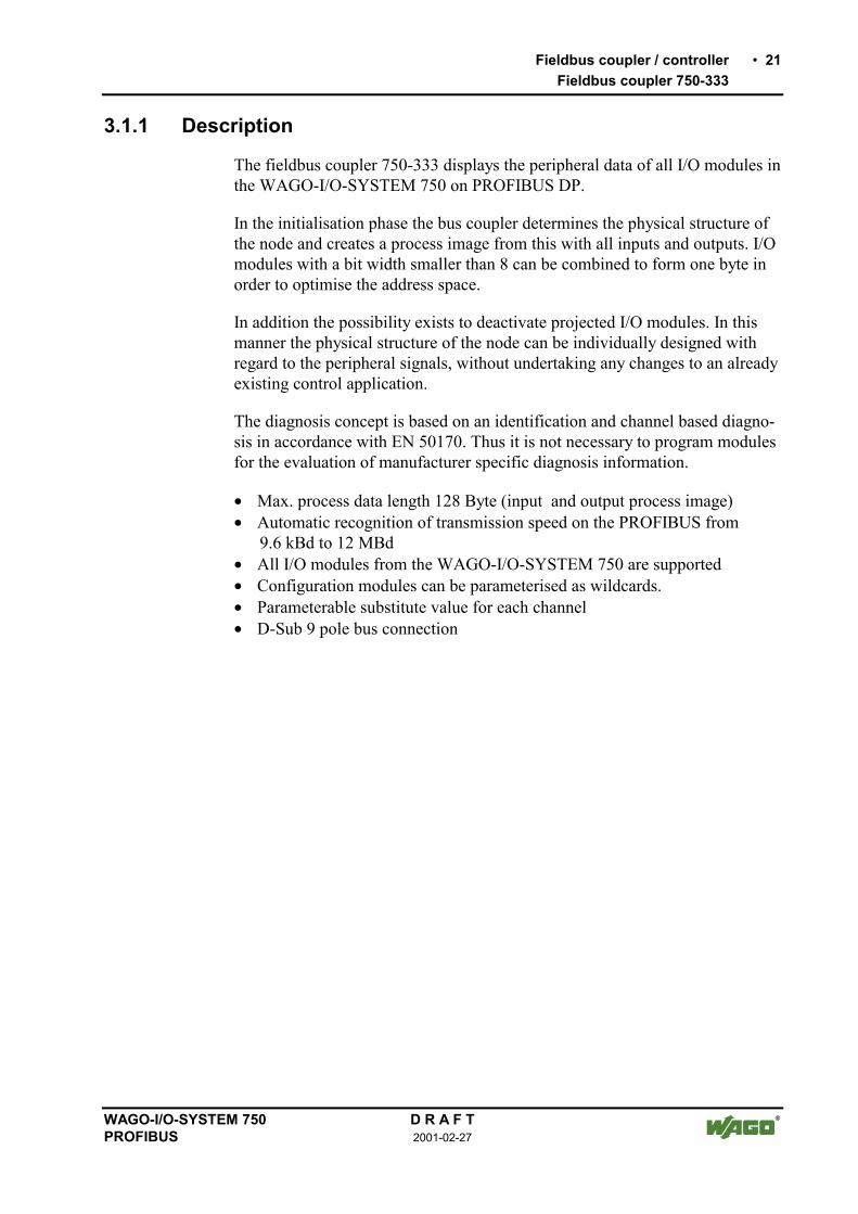
3.1.1 Description
The fieldbus coupler 750-333 displays the peripheral data of all I/O modules inthe WAGO-I/O-SYSTEM 750 on PROFIBUS DP.
In the initialisation phase the bus coupler determines the physical structure ofthe node and creates a process image from this with all inputs and outputs. I/Omodules with a bit width smaller than 8 can be combined to form one byte inorder to optimise the address space.
In addition the possibility exists to deactivate projected I/O modules. In thismanner the physical structure of the node can be individually designed withregard to the peripheral signals, without undertaking any changes to an alreadyexisting control application.
The diagnosis concept is based on an identification and channel based diagno-sis in accordance with EN 50170. Thus it is not necessary to program modulesfor the evaluation of manufacturer specific diagnosis information.
• Max. process data length 128 Byte (input and output process image)• Automatic recognition of transmission speed on the PROFIBUS from
9.6 kBd to 12 MBd• All I/O modules from the WAGO-I/O-SYSTEM 750 are supported• Configuration modules can be parameterised as wildcards.• Parameterable substitute value for each channel• D-Sub 9 pole bus connection

22 Fieldbus coupler / controllerFieldbus coupler 750-333
D R A F T WAGO-I/O-SYSTEM 7502001-02-27 PROFIBUS
3.1.2 Hardware
3.1.2.1 View
24V 0V
+ +
- -
PE PE
01 02
750
-333
RUN
BF
DIA
I/O
PROFIBUS
x10123
45678
9
x100123
45678
9
ADDRESS
C
DB
A
BUS Versorgung24V0V
0V
Leistungskontakte
Status derBetriebsspannung-Leistungskontakte-System
Versorgung überLeistungskontakte24V
Datenkontakte
Feldbus-anschlussD-Sub
Adresse
Adresse
Konfigurations-Schnittstelle
Fig. 3-1: Fieldbus coupler 750-333 PROFIBUS DP/V1 g033300d
The fieldbus coupler comprises of:
• Supply module with Internal system supply module for the system supplyas well as power jumper contacts for the field supply via I/O module as-semblies.
• Fieldbus interface with the bus connection
• 2 rotary switches for the station address (decimal)
• Display elements (LED's) for status display of the operation, the bus com-munication, the operating voltages as well as for fault messages and diag-nosis
• Electronics for communication with the I/O modules (internal bus) and thefieldbus interface

Fieldbus coupler / controller 23Fieldbus coupler 750-333
WAGO-I/O-SYSTEM 750 D R A F TPROFIBUS 2001-02-27
3.1.2.2 Device supply
The supply is made via terminal bocks with CAGE CLAMP® connection. Thedevice supply is intended both for the system and the field units.
1
2
3
4
5
6
7
8
750-333
24V
10nF
24V
10nF
0V
DC
DC24V/0V
24V
0V
0V
ELEKTRONIK
Bus-klemmen
FELDBUSINTERFACE
ELEK
TR
ONIK
FELD
BU
SIN
TER
FAC
E
Fig. 3-2: Device supply g012105d
The integrated internal system supply module generates the necessary voltageto supply the electronics and the connected I/O modules.
The fieldbus interface is supplied with electrically isolated voltage from theinternal system supply module.

24 Fieldbus coupler / controllerFieldbus coupler 750-333
D R A F T WAGO-I/O-SYSTEM 7502001-02-27 PROFIBUS
3.1.2.3 Fieldbus connection
The PROFIBUS interface is designed as a Sub-D connection in accordancewith the US Standard EIA RS 485 for cable linked data transmission.
16
7
8
9
2
3
4
5
9-pol. D-Sub-Buchse
DGND
RTS
RxD/TxD-PRxD/TxD-N
VP
Fig. 3-3: Bus connection, D-SUB g012102d
Pin Signal Description
3 RxD(TxD)-P Transmit (receive) signal
4 RTS Ready To Send
5 GND Supply ground (earth)
6 Vcc Voltage supply
8 RxD(TxD) N Transmit (receive) signal
The electrical isolation between the fieldbus system and the electronics isachieved by means of DC/DC converters and optocouplers in the fieldbus in-terface.
The connection point is mechanically lowered permitting fitting in an 80 mmhigh switch box once connected.

Fieldbus coupler / controller 25Fieldbus coupler 750-333
WAGO-I/O-SYSTEM 750 D R A F TPROFIBUS 2001-02-27
3.1.2.4 Display elements
The operating condition of the fieldbus coupler or node is signalled via lightdiodes (LED).
24V 0V
+ +
RUN
BF
DIA
BUS
I/O
PROFIBUS
C
DB
A
Fig. 3-4: Display elements 750-333 g012106x
LED Colour Meaning
RUN green The 'RUN' LED indicates to the operator if the fieldbus coupler /controller is correctly initialised.
BF red The 'BF'-LED indicates whether the communication functions viathe PROFIBUS.
DIA red The 'DIA' LED indicates an external diagnosis. The signalling is notsupported by all devices.
BUS red The 'BUS'-LED signals a projecting fault.
IO red /green/ orange
The 'I/O'-LED indicates the operation of the node and signals faultsencountered.
A green Status of the operating voltage system
C green Status of the operating voltage power jumper contacts

26 Fieldbus coupler / controllerFieldbus coupler 750-333
D R A F T WAGO-I/O-SYSTEM 7502001-02-27 PROFIBUS
3.1.2.5 Station address
The station address (decimal) is determined using two rotary switches on theelectronic module.
x100123
45678
9
ADDRESS
x10123
45678
9
Fig. 3-5: Setting the station address g012102d
The switch x1 determines the units position of the address. The switchx10 determines the tens positions of the address. Valid station addresses arebetween 1 and 99. The coupler also permits the station address 0.
The station address is taken over by the fieldbus coupler after switching on thedevice (initialisation phase). Adjustments of the switch have no effect duringoperation.
3.1.2.6 Configuration interface
The configuration interface used for the communication with WAGO-I/O-CHECK or for firmware upload is located behind the cover flap.
Konfigurations-Schnittstelle
Klappeöffnen
Fig. 3-6: Configuration interface g01xx06d
The communication cable (750-920) is connected to the 4 pole header.

Fieldbus coupler / controller 27Fieldbus coupler 750-333
WAGO-I/O-SYSTEM 750 D R A F TPROFIBUS 2001-02-27
3.1.3 Operating system
Following the configuration of the master activation and the electrical installa-tion if the fieldbus station can start up the system.
After switching on the supply voltage the coupler performs a self test of allfunctions of its devices, the I/O module and the fieldbus interface. Followingthis the I/O modules and the present configuration is determined, whereby anexternal not visible list is generated. This list includes an input and an outputarea on which is represented the fieldbus RAM of the protocol chip.
In the event of a fault the coupler changes to the "Stop" condition. The "I/O"LED flashes red. After a fault free start up the coupler changes to the "Fieldbusstart" status and the "I/O" LED lights up green.
Koppler-Selbsttest,Ermittlung Busklemmen
und Konfiguration,Erstellung interner Liste
“I/O”-LED blinkt rot
Versorgungsspannungeinschalten
Feldbusstart“I/O”-LED leuchtet grün
JaFehler
Nein
Stop“I/O”-LED blinkt rot
Fig. 3-7: Operating system 750-333 g012113d

28 Fieldbus coupler / controllerFieldbus coupler 750-333
D R A F T WAGO-I/O-SYSTEM 7502001-02-27 PROFIBUS
3.1.4 Process image
3.1.4.1 Local process image
After switching on, the coupler recognises all I/O modules plugged into thenode which supply or wait for data (data width/bit width > 0). In nodes analogand digital I/O modules can be mixed.
NoteFor the number of input and output bits or bytes of the individually activatedon I/O modules please refer to the corresponding I/O module description.
The coupler produces an internal process image from the data width and thetype of type of I/O module as well as the position of the I/O modules in thenode. It is divided into an input and an output data area.
The data of the digital I/O modules is bit orientated, i.e. the data exchange ismade bit for bit. The analog I/O modules are representative for all byte orien-tated I/O modules, i.e. those where the data exchange is made byte for byte.These I/O modules include for example the counter modules, I/O modules forangle and path measurement as well as the communication modules.
The data of the I/O modules is separated for the local input and output processimage in the sequence of their position after the coupler in the individual proc-ess image.
NoteA process image restructuring may result if a node is changed or extended. Inthis case the process data addresses also change in comparison with earlierones.

Fieldbus coupler / controller 29Fieldbus coupler 750-333
WAGO-I/O-SYSTEM 750 D R A F TPROFIBUS 2001-02-27
3.1.4.2 Allocation of the input and output data
The process data is exchanged via the PROFIBUS with the higher rankingcontrols (master). A maximum of 128 bytes of data is transmitted from themaster to the coupler or from the node to the output data. The coupler re-sponds by returning a maximum of 128 bytes input data to the master.
Modules are configured when projecting the node which can be taken overfrom a hardware catalogue of the configuration programs. The informationcovering the possible modules is contained in the GSD files.
The coupler generates an internal mapping in accordance with the installed andconfigured settings of the node, in which the allocation of the input and outputdata is determined in the local process image with the position in thePROFIBUS DP Telegram.
402
DI
402 452 452 504 504 550 550 600
1 2 3 4 5 6 7 8 9750-DI AIAI DODO AOAO
PROFIBUS
PROFIBUS
I I
OO
I
OO
I
I
O
AnschaltungCPU
bit- und byteweiseZuordnung,
Erstellung automatischdurch den Koppler
byteweise Zuordnung,Erstellung auf dem PC
ZuordnungslisteZuordnungsliste
Master, z. B. SPS
Master-Adressen
Fig. 3-8: Allocation of the input and output data g012117d

30 Fieldbus coupler / controllerFieldbus coupler 750-333
D R A F T WAGO-I/O-SYSTEM 7502001-02-27 PROFIBUS
3.1.5 Configuration
The configuration of the node is performed in accordance with the physical re-quirements of the fieldbus coupler and I/O modules.
The fieldbus coupler or the process data channel is to be configured on the firstslot.The other slots are configured in accordance with the physical requirements ofthe I/O modules. Here only I/O modules with process data are relevant. Thesupply modules without diagnosis, bus internal system supply module and thetermination module are to be ignored for the configuration because they do notprovide any process data.
One or tow modules are entered in the hardware catalogue for each I/O mod-ule. The module appear as 750-xyz ..., for example 750-400 2 DI/24 V DC/3.0ms.
For all binary modules an addition is made to the entry *750-xyz .... When us-ing these denominations the coupler adds the binary information to the currentmodule in a byte which was previously opened with 750-xyz .... The use of a* module is only permitted when the number of channels is less than orequal to the remaining bits in the previously opened byte. The binary I/O mod-ules combined in a byte can be arranged at separate locations, i.e. binary I/Omodules with a different signal type or also byte orientated I/O modules can beconnected between.
In order to be able to individually arrange the scope of connected peripheryunits independent of the control program, it is possible to parameterise I/Omodules in the configuration table as not connected. In this manner processdata still present is filtered for the individual module and not transferred on thePROFIBUS DP to and read by the periphery units.

Fieldbus coupler / controller 31Fieldbus coupler 750-333
WAGO-I/O-SYSTEM 750 D R A F TPROFIBUS 2001-02-27
3.1.5.1 GSD files
Under PROFIBUS DP the features of the modules are defined by the manu-facturers in the form of a GSD file (unit basic data).
Structure, content and coding of this unit main data are standardised and madeavailable to the user allowing to project optional DP slaves using the projectunits of various manufacturers.
iFurther informationThe PNO provides information about the GSD files of all listed manufactur-ers.
GSD and symbol files for the configuration of the I/O modules are availableunder the order number 750-910 on disks or from the WAGO INTERNETpage.
http://www.wago.com
GSD file for I/O-Module 750-333 WAGOB754.GSD
The GSD file is read by the configuration software and the corresponding set-tings transmitted. For the necessary inputs and handling steps please refer tothe software user manuals.

32 Fieldbus coupler / controllerFieldbus coupler 750-333
D R A F T WAGO-I/O-SYSTEM 7502001-02-27 PROFIBUS
3.1.5.2 Identification bytes
The identification bytes contain information about the design and structure ofthe unit inputs and outputs. For projecting each I/O module, or each channel isallocated an identification (module).
Bit Meaning
7 6 5 4 3 2 1 0
000...1
000...1
001...1
010...1
Data length1 byte or word2 bytes or words3 bytes or words...16 bytes or words
0011
0101
Input and outputspec. identification formatsInputOutputInput and output
01
Format0 = Byte structure1 = Word structure
01
Consistence overByte or wordTotal length
This information is saved in the GSD file. During projecting the I/O module isselected in accordance with the article number using the configuration soft-ware in the hardware catalogue.
Module Ident. Module Ident750-333 No process data channel 0x00 750-333 2 Byte process data channel 0xB1750-400 2 DI/24 V DC/3.0 ms 0x10 *750-400 2 DI/24 V DC/3.0 ms 0x00750-401 2 DI/24 V DC/0.2 ms 0x10 *750-401 2 DI/24 V DC/0.2 ms 0x00750-402 4 DI/24 V DC/3.0 ms 0x10 *750-402 4 DI/24 V DC/3.0 ms 0x00750-403 4 DI/24 V DC/0.2 ms 0x10 *750-403 4 DI/24 V DC/0.2 ms 0x00750-404 Counter Module 0xF2750-405 2 DI/230 V AC/10 ms 0x10 *750-405 2 DI/230 V AC/10 ms 0x00750-406 2 DI/120 V AC/10 ms 0x10 *750-406 2 DI/120 V AC/10 ms 0x00750-408 4 DI/24 V DC/3.0 ms 0x10 *750-408 4 DI/24 V DC/3.0 ms 0x00750-409 4 DI/24 V DC/0.2 ms 0x10 *750-409 4 DI/24 V DC/0.2 ms 0x00750-410 2 DI/24 V DC/3.0 ms 0x10 *750-410 2 DI/24 V DC/3.0 ms 0x00750-411 2 DI/24 V DC/0.2 ms 0x10 *750-411 2 DI/24 V DC/0.2 ms 0x00750-412 2 DI/48 V DC/3.0 ms 0x10 *750-412 2 DI/48 V DC/3.0 ms 0x00750-413 2 DI/48 V DC/0.2 ms 0x10 *750-413 2 DI/48 V DC/0.2 ms 0x00750-414 4 DI/5 V DC/0.2 ms 0x10 *750-414 4 DI/5 V DC/0.2 ms 0x00750-415 4 DI/24 V AC/DC/20 ms 0x10 *750-415 4 DI/24 V AC/DC/20 ms 0x00750-418 2 DI/24 V DC DIA ACK 0x30 *750-418 2 DI/24 V DC DIA ACK 0x00750-419 2 DI/24 V DC DIA 0x10 *750-419 2 DI/24 V DC DIA 0x00750-423 4 DI/24 V AC/DC/50 ms 0x10 *750-423 4 DI/24 V AC/DC/50 ms 0x00750-424 2 DI/24 V DC DIA 0x10 *750-424 2 DI/24 V DC DIA 0x00750-452 2 AI/0-20 mA/diff. 0x51750-454 2 AI/4-20 mA/diff. 0x51750-456 2 AI/±10 V/diff. 0x51750-461 2 AI/RTD 0x51

Fieldbus coupler / controller 33Fieldbus coupler 750-333
WAGO-I/O-SYSTEM 750 D R A F TPROFIBUS 2001-02-27
Module Ident. Module Ident750-462 2 AI/TC 0x51750-465 2 AI/0-20 mA/SE 0x51750-466 2 AI/4-20 mA/SE 0x51750-467 2 AI/0-10 V/SE 0x51750-468 4 AI/0-10 V/SE 0x53750-469 2 AI/TC/OCM 0x51750-472 2 AI/0-20 mA/OVLP 0x51750-474 2 AI/4-20 mA/OVLP 0x51750-476 2 AI/±10 V 0x51750-478 2 AI/0-10 V 0x51750-501 2 DO/24 V DC/0.5 A 0x20 *750-501 2 DO/24 V DC/0.5 A 0x00750-502 2 DO/24 V DC/2.0 A 0x20 *750-502 2 DO/24 V DC/2.0 A 0x00750-504 4 DO/24 V DC/0.5 A 0x20 *750-504 4 DO/24 V DC/0.5 A 0x00750-506 2 DO/24 V DC/0.5 A DIA 0x20 *750-506 2 DO/24 V DC/0.5 A DIA 0x00750-507 2 DO/24 V DC/2.0 A DIA 0x20 *750-507 2 DO/24 V DC/2.0 A DIA 0x00750-509 2 DO/230 V AC/0.3 A 0x20 *750-509 2 DO/230 V AC/0.3 A 0x00750-511 2 DO 24 V DC/PWM 0xF2750-512 2 DO Relay/250 V AC 0x20 *750-512 2 DO Relay/250 V AC 0x00750-513 2 DO Relay/250 V AC 0x20 *750-513 2 DO Relay/250 V AC 0x00750-514 2 DO Relay/125 V AC 0x20 *750-514 2 DO Relay/125 V AC 0x00750-516 4 DO/24 V DC/0.5 A 0x20 *750-516 4 DO/24 V DC/0.5 A 0x00750-517 2 DO Relay/230 V AC 0x20 *750-517 2 DO Relay/230 V AC 0x00750-519 4 DO/5 V DC/20 mA 0x20 *750-519 4 DO/5 V DC/20 mA 0x00750-522 2 DO/230V AC/0.5 A DIA 0x20 *750-522 2 DO/230V AC/0.5 A DIA 0x00750-550 2 AO/0-10 V 0x61750-552 2 AO/0-20 mA 0x61750-554 2 AO/4-20 mA 0x61750-556 2 AO/±10 V 0x61750-610 P supply 24 V DC/DIA 0x00750-611 P supply 230 V AC/DIA 0x00750-630 SSI-Intf. standard 0x95750-630 SSI-Intf. alternative 0x93750-631 Encoder Intf. 0xB5750-650 RS232C Intf. 5 Byte 0xB5750-650 RS232C Intf. 3 Byte 0xB3750-651 TTY Intf. 5 Byte 0xB5750-651 TTY Intf. 3 Byte 0xB3750-653 RS485 Intf. 5 Byte 0xB5750-653 RS485 Intf. 3 Byte 0xB3750-654 Data Exch. Module 0xF1

34 Fieldbus coupler / controllerFieldbus coupler 750-333
D R A F T WAGO-I/O-SYSTEM 7502001-02-27 PROFIBUS
3.1.5.3 Example
The allocation should become clear by way of a fieldbus node with a couplerand 17 I/O modules.
402
DI DI DI DI DI DI
402 402 452 602 504 504 504504 504 602602 600550 550452 452 504
1 2 3 4 5 6 7 8 9 10 11 12 13 14 15 16 17
PROFIBUS
AI AI DO DODO DO DO DO DO DODO DO DO DO AO AO AI AI AO AO AI AI DO DO
75
0-3
33
Fig. 3-9: Example application g012115x
I/O modules PI Master *No. ModulIdentification Inputs Outputs
Digital input 750-402 4 DI/24 V DC/3.0 ms EB12.0
Digital input 0x10 EB12.1
Digital input EB12.2
1
Digital input EB12.3
Digital input *750-402 4 DI/24 V DC/3.0 ms EB12.4
Digital input 0x00 EB12.5
Digital input EB12.6
2
Digital input EB12.7
Digital input 750-402 4 DI/24 V DC/3.0 ms EB13.0
Digital input 0x10 EB13.1
Digital input EB13.2
3
Digital input EB13.3
Analog input 750-452 2 AI/0-20 mA/diff. EW04
Analog input 0x51 EW2
5 Potential supply Potential supply --- ---
Digital output 750-504 4 DO/24 V DC/0.5 A AB8.0
Digital output 0x20 AB8.1
Digital output AB8.2
6
Digital output AB8.3
Digital output *750-504 4 DO/24 V DC/0.5 A AB8.4
Digital output 0x00 AB8.5
Digital output AB8.6
7
Digital output AB8.7

Fieldbus coupler / controller 35Fieldbus coupler 750-333
WAGO-I/O-SYSTEM 750 D R A F TPROFIBUS 2001-02-27
Digital output 750-504 4 DO/24 V DC/0.5 A AB9.0
Digital output 0x20 AB9.1
Digital output AB9.2
8
Digital output AB9.3
Digital output *750-504 4 DO/24 V DC/0.5 A AB9.4
Digital output 0x00 AB9.5
Digital output AB9.6
9
Digital output AB9.7
10 Potential supply Potential supply --- ---
Analog output 750-550 2 AO/0-10 V AW011
Analog output 0x61 AW2
Analog input 750-452 2 AI/0-20 mA/diff. EW412
Analog input 0x51 EW6
Analog output 750-550 2 AO/0-10 V AW413
Analog output 0x61 AW6
Analog input 750-452 2 AI/0-20 mA/diff. EW814
Analog input 0x51 EW10
15 Potential supply Potential supply --- ---
Digital output 750-504 4 DO/24 V DC/0.5 A AB10.0
Digital output 0x20 AB10.1
Digital output AB10.2
16
Digital output AB10.3
17 End module End module --- ---
* The master addresses listed in the table correspond to the allocation of the process datagiven in the master configuration.

36 Fieldbus coupler / controllerFieldbus coupler 750-333
D R A F T WAGO-I/O-SYSTEM 7502001-02-27 PROFIBUS
3.1.6 Parameterising the coupler
Before a data exchange is possible between the master and slaves a param-eterisation is necessary in addition to the configuration.
The extended parameters (extended User_Prm_Data) is available as a select-able text in the configuration programs using the GSD files.
Description Value MeaningRestart the internal bus after afault
Restart of the internal bus following a fault,such as missing termination module,
POWER ON RESET*) after interruption of the I/O module supplyAUTORESET immediately after overcoming I/O module fault
I/O module diagnosis The diagnosis information about all diagnosiscapable I/O modules, with which the diagnosisis released are
released*) transferred to PROFIBUS-DP masterlock not transferred to PROFIBUS-DP master
Process value display Word or double word orientated process data istransferred to the PROFIBUS-DP master in:
INTEL Little Endian FormatMOTOROLA*) Big Endian Format
Behaviour in case of aPROFIBUS DP fault
In the case of a fault with the PROFIBUS DPcommunication the status of the inserted outputperiphery can be influenced in various manners:
Stop internal bus transmis-sion
the process data exchange of the internal bus isstopped, all outputs drop out after a modulespecific monitoring time of 100 ms
Set start image to zero all outputs are reset immediatelyFreeze starting image all outputs contain the last status before the
faultWrite substitute values*) all outputs switch a parameter substitute value
Reaction to internal bus faults In the case of a fault with the internal commu-nication between the fieldbus coupler and I/Omodules, such as, for example: no terminationmodule,
Stop PROFIBUS dataexchange*)
the data exchange with the PROFIBUS masteris stopped.
Set start image to zero the input information is set to zero
Freeze starting image the input information before the fault is main-tained
*) Default settings
Fieldbus coupler / controller 37Fieldbus coupler 750-333
WAGO-I/O-SYSTEM 750 D R A F TPROFIBUS 2001-02-27
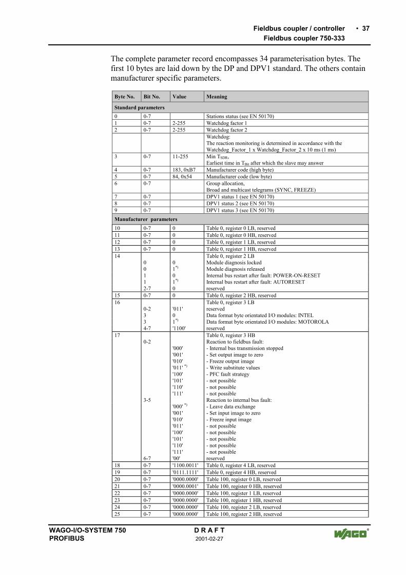
The complete parameter record encompasses 34 parameterisation bytes. Thefirst 10 bytes are laid down by the DP and DPV1 standard. The others containmanufacturer specific parameters.
Byte No. Bit No. Value Meaning
Standard parameters0 0-7 Stations status (see EN 50170)1 0-7 2-255 Watchdog factor 12 0-7 2-255 Watchdog factor 2
Watchdog:The reaction monitoring is determined in accordance with theWatchdog_Factor_1 x Watchdog_Factor_2 x 10 ms (1 ms)
3 0-7 11-255 Min TSDR,Earliest time in TBit after which the slave may answer
4 0-7 183, 0xB7 Manufacturer code (high byte)5 0-7 84, 0x54 Manufacturer code (low byte)6 0-7 Group allocation,
Broad and multicast telegrams (SYNC, FREEZE)7 0-7 DPV1 status 1 (see EN 50170)8 0-7 DPV1 status 2 (see EN 50170)9 0-7 DPV1 status 3 (see EN 50170)Manufacturer parameters10 0-7 0 Table 0, register 0 LB, reserved11 0-7 0 Table 0, register 0 HB, reserved12 0-7 0 Table 0, register 1 LB, reserved13 0-7 0 Table 0, register 1 HB, reserved14 Table 0, register 2 LB
0 0 Module diagnosis locked0 1*) Module diagnosis released1 0 Internal bus restart after fault: POWER-ON-RESET1 1*) Internal bus restart after fault: AUTORESET2-7 0 reserved
15 0-7 0 Table 0, register 2 HB, reserved16 Table 0, register 3 LB
0-2 '011' reserved3 0 Data format byte orientated I/O modules: INTEL3 1*) Data format byte orientated I/O modules: MOTOROLA4-7 '1100' reserved
17 Table 0, register 3 HB0-2 Reaction to fieldbus fault:
'000''001''010''011' *)
'100''101''110''111'
- Internal bus transmission stopped- Set output image to zero- Freeze output image- Write substitute values- PFC fault strategy- not possible- not possible- not possible
3-5 Reaction to internal bus fault:'000' *)
'001''010''011''100''101''110''111'
- Leave data exchange- Set input image to zero- Freeze input image- not possible- not possible- not possible- not possible- not possible
6-7 '00' reserved18 0-7 '1100.0011' Table 0, register 4 LB, reserved19 0-7 '0111.1111' Table 0, register 4 HB, reserved20 0-7 '0000.0000' Table 100, register 0 LB, reserved21 0-7 '0000.0001' Table 100, register 0 HB, reserved22 0-7 '0000.0000' Table 100, register 1 LB, reserved23 0-7 '0000.0000' Table 100, register 1 HB, reserved24 0-7 '0000.0000' Table 100, register 2 LB, reserved25 0-7 '0000.0000' Table 100, register 2 HB, reserved

38 Fieldbus coupler / controllerFieldbus coupler 750-333
D R A F T WAGO-I/O-SYSTEM 7502001-02-27 PROFIBUS
3.1.7 Configuring the process data channel
The process data channel serves for the communication between the couplerand the higher ranking systems (Master or projecting and diagnosis PC).This channel is allocated to the coupler. The fieldbus coupler 750-333 does notuse the process data channel.
Module Identificationhex
Identificationdec.
750-333 No process data channel 0x00 0
NoteThe module 750-333 no process data channel should be configured as the1st module.

Fieldbus coupler / controller 39Fieldbus coupler 750-333
WAGO-I/O-SYSTEM 750 D R A F TPROFIBUS 2001-02-27
3.1.8 Configuration and parameterisation of I/O modules
3.1.8.1 Digital I/O modules
All binary I/O modules contain parameterisation information extended by 3bytes, to serve, amongst others, for identification on the internal bus and thestructure of the mapping table. With diagnosis capable terminals the diagnosismessage can be suppressed or released for a channel or module. Binary outputsoffer the alternative to switch to parameterisable substitute values in the caseof a master failure.
NoteFor simplification the tables only show the article number for the moduledesignation. The module 750-400 thus corresponds to the module 750-4002 DI/24 V DC/3.0 ms
3.1.8.1.1 2 DI I/O modules
Module Identificationhex
Identificationdec
750-400, 750-401, 750-405, 750-406, 750-410,750-411, 750-412
0x10 16
*750-400, *750-401, *750-405, *750-406, *750-410, *750-411, *750-412
0x00 0
Parameter Value MeaningI/O module is physically The I/O module process data is:
plug fitted*) - supplied by the I/O modulenot plug fitted - set to zero by the coupler
*) Default settings
ParameterOffset Information0 7 6 5 4 3 2 1 0
0 0 Plug 0 0 0 0 01 7 6 5 4 3 2 1 0
0 0 0 0 0 0 0 12 7 6 5 4 3 2 1 0
0 0 0 0 0 0 0 0
Plug5 01
Module is physically not presentModule is physically present (default)
Italic Cannot be changed

40 Fieldbus coupler / controllerFieldbus coupler 750-333
D R A F T WAGO-I/O-SYSTEM 7502001-02-27 PROFIBUS
3.1.8.1.2 4 DI I/O modules
Module Identificationhex
Identificationdec
750-402, 750-403, 750-408, 750-409, 750-414, 750-415,750-423, 750-422, 750-424
0x10 16
*750-402, *750-403, *750-408, *750-409, *750-414, *750-415, *750-423, *750-422, *750-424
0x00 0
Parameter Value MeaningI/O module is physically The I/O module process data is:
plug fitted*) - supplied by the I/O modulenot plug fitted - Set to zero by the coupler
*) Default settings
ParameterOffset Information0 7 6 5 4 3 2 1 0
0 0 Plug 0 0 0 0 11 7 6 5 4 3 2 1 0
0 0 0 0 0 0 0 12 7 6 5 4 3 2 1 0
0 0 0 0 0 0 0 0
Plug5 01
Module is physically not presentModule is physically present (default)
Italic Cannot be changed

Fieldbus coupler / controller 41Fieldbus coupler 750-333
WAGO-I/O-SYSTEM 750 D R A F TPROFIBUS 2001-02-27
3.1.8.1.3 2 DI I/O modules modules with 1 bit diagn. per channel
Module Identificationhex
Identificationdec
750-419, 750-425 0x10 16*750-419, *750-425 0x00 0
Parameter Value MeaningI/O module is physically The I/O module process data is:
plug fitted*) - supplied by the I/O modulenot plug fitted - set to zero by the coupler
Diagnosis channel x The diagnosis information of the correspondingchannel is
released - transmitted to PROFIBUS-DP masterlocked*) - not transmitted to PROFIBUS-DP master
*) Default settings
ParameterOffset Information0 7 6 5 4 3 2 1 0
0 0 Plug 0 DiagEn1
DiagEn0
0 1
1 7 6 5 4 3 2 1 0
0 0 0 0 0 1 0 12 7 6 5 4 3 2 1 0
0 0 0 0 0 0 0 0
Plug5 01
Module is physically not presentModule is physically present (default)
DiagEn1301
Diagnosis idle run, short circuit on channel 2lockedreleased
DiagEn0201
Diagnosis idle run, short circuit on channel 1lockedreleased
Italic cannot be changed

42 Fieldbus coupler / controllerFieldbus coupler 750-333
D R A F T WAGO-I/O-SYSTEM 7502001-02-27 PROFIBUS
3.1.8.1.4 2 DO I/O modules
Module Identificationhex
Identificationdec
750-501, 750-502, 750-509, 750-512, 750-513,750-514, 750-517
0x20 32
*750-501, *750-502, *750-509, *750-512, *750-513,*750-514, *750-517
0x00 0
Parameter Value MeaningI/O module is physically The I/O module process data is:
plug fitted*) - supplied to the I/O modulenot plug fitted - ignored by the coupler
Substitute channel x0*)
1
If, in the case of a PROFIBUS-DP fault, theswitching of substitute values is enabled by thebus coupler parameterisation, this data is trans-mitted to the periphery in the case of a fault.
*) Default settings
ParameterOffset Information0 7 6 5 4 3 2 1 0
0 0 Plug 0 0 0 0 01 7 6 5 4 3 2 1 0
0 0 0 0 0 0 1 02 7 6 5 4 3 2 1 0
0 0 0 0 0 0 SV1 SV0
Plug5 01
Module is physically not presentModule is physically present (default)
SV00 Substitute value for channel 1SV01 Substitute value for channel 2Italic Cannot be changed

Fieldbus coupler / controller 43Fieldbus coupler 750-333
WAGO-I/O-SYSTEM 750 D R A F TPROFIBUS 2001-02-27
3.1.8.1.5 2 DO I/O modules with 1 bit diagn. per channel
Module Identificationhex
Identificationdec
750-507, 750-522 0x20 32*750-507, *750-522 0x00 0
Parameter Value MeaningI/O module is physically The I/O module process data is:
plug fitted*) - supplied to the I/O modulenot plug fitted - ignored by the coupler
Diagnosis channel x The diagnosis information of the correspondingchannel is
released*) - transmitted to PROFIBUS-DP masterlocked - not transmitted to PROFIBUS-DP master
Substitute channel x0*)
1
If, in the case of a PROFIBUS-DP fault, theswitching of substitute values is enabled by thebus coupler parameterisation, this data is trans-mitted to the periphery in the case of a fault.
*) Default settings
ParameterOffset Information0 7 6 5 4 3 2 1 0
0 0 Plug 0 DiagEn1
DiagEn0
0 0
1 7 6 5 4 3 2 1 0
0 0 0 0 0 0 1 12 7 6 5 4 3 2 1 0
0 0 0 0 0 0 SV1 SV0
Plug5 01
Module is physically not presentModule is physically present (default)
DiagEn0201
Diagnosis idle run, overload, short circuit on channel 1lockrelease
DiagEn1301
Diagnosis idle run, overload, short circuit on channel 2lockedreleased
SV00 Substitute value for channel 1SV01 Substitute value for channel 2Italic Cannot be changed

44 Fieldbus coupler / controllerFieldbus coupler 750-333
D R A F T WAGO-I/O-SYSTEM 7502001-02-27 PROFIBUS
3.1.8.1.6 2 DO I/O module with 2 bit diagn. per channel
Module Informationhex
Informationdec
750-506 0x20 32*750-506 0x00 0
Parameter Value MeaningI/O module is physically The I/O module process data is:
plug fitted*) - supplied to the I/O modulenot plug fitted - ignored by the coupler
Diagnosis channel x The diagnosis information of the correspondingchannel is
released*) - transmitted to PROFIBUS-DP masterlocked - not transmitted to PROFIBUS-DP master
Substitute channel x0*)
1
If, in the case of a PROFIBUS-DP fault, theswitching of substitute values is enabled by thebus coupler parameterisation, this data is trans-mitted to the periphery in the case of a fault.
*) Default settings
ParameterOffset Information0 7 6 5 4 3 2 1 0
0 0 Plug 0 DiagEn1
DiagEn0
0 1
1 7 6 5 4 3 2 1 0
0 0 0 0 0 0 1 12 7 6 5 4 3 2 1 0
0 0 0 0 0 0 SV1 SV0
Plug5 01
Module is physically not presentModule is physically present (default)
DiagEn0201
Diagnosis idle run, short circuit, lower voltage on channel 1lockedreleased
DiagEn1301
Diagnosis idle run, short circuit, lower voltage on channel 2lockedreleased
SV00 Substitute value for channel 1SV01 Substitute value for channel 2Italic cannot be changed

Fieldbus coupler / controller 45Fieldbus coupler 750-333
WAGO-I/O-SYSTEM 750 D R A F TPROFIBUS 2001-02-27
3.1.8.1.7 4 DO I/O modules
Module Identificationhex
Identificationdec
750-504, 750-516, 750-519 0x20 32*750-504, *750-516, *750-519 0x00 0
Parameter Value MeaningI/O module is physically The I/O module process data is:
plug fitted*) - supplied by the I/O modulenot plug fitted - ignored by the coupler
Substitute channel x0*)
1
If, in the case of a PROFIBUS-DP fault, theswitching of substitute values is enabled by thebus coupler parameterisation, this data is trans-mitted to the periphery in the case of a fault.
*) Default settings
ParameterOffset Information0 7 6 5 4 3 2 1 0
0 0 Plug 0 0 0 0 11 7 6 5 4 3 2 1 0
0 0 0 0 0 0 1 02 7 6 5 4 3 2 1 0
0 0 0 0 SV3 SV2 SV1 SV0
Plug5 01
Module is physically not presentModule is physically present (default)
SV00 Substitute value for channel 1SV01 Substitute value for channel 2SV02 Substitute value for channel 3SV03 Substitute value for channel 4Italic Cannot be changed
46 Fieldbus coupler / controllerFieldbus coupler 750-333
D R A F T WAGO-I/O-SYSTEM 7502001-02-27 PROFIBUS
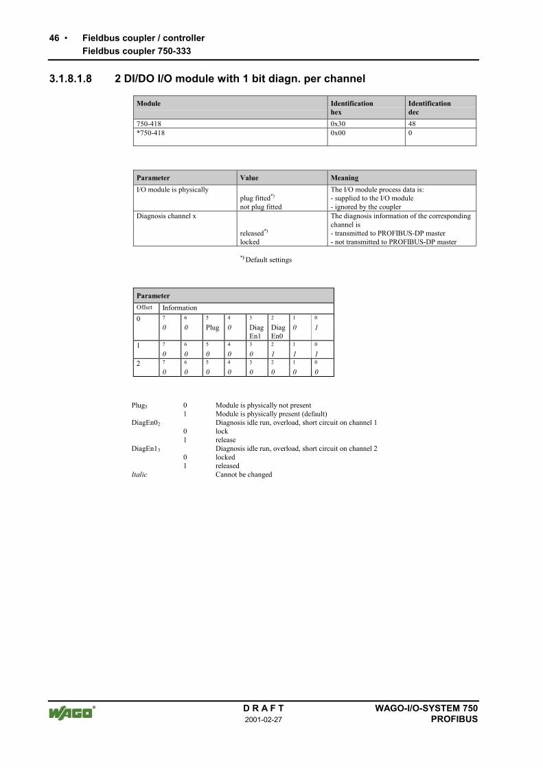
3.1.8.1.8 2 DI/DO I/O module with 1 bit diagn. per channel
Module Identificationhex
Identificationdec
750-418 0x30 48*750-418 0x00 0
Parameter Value MeaningI/O module is physically The I/O module process data is:
plug fitted*) - supplied to the I/O modulenot plug fitted - ignored by the coupler
Diagnosis channel x The diagnosis information of the correspondingchannel is
released*) - transmitted to PROFIBUS-DP masterlocked - not transmitted to PROFIBUS-DP master
*) Default settings
ParameterOffset Information0 7 6 5 4 3 2 1 0
0 0 Plug 0 DiagEn1
DiagEn0
0 1
1 7 6 5 4 3 2 1 0
0 0 0 0 0 1 1 12 7 6 5 4 3 2 1 0
0 0 0 0 0 0 0 0
Plug5 01
Module is physically not presentModule is physically present (default)
DiagEn0201
Diagnosis idle run, overload, short circuit on channel 1lockrelease
DiagEn1301
Diagnosis idle run, overload, short circuit on channel 2lockedreleased
Italic Cannot be changed
Fieldbus coupler / controller 47Fieldbus coupler 750-333
WAGO-I/O-SYSTEM 750 D R A F TPROFIBUS 2001-02-27
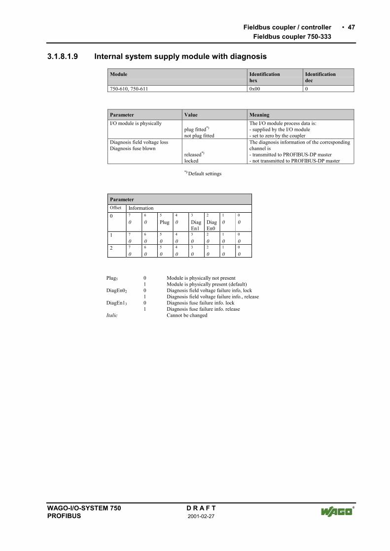
3.1.8.1.9 Internal system supply module with diagnosis
Module Identificationhex
Identificationdec
750-610, 750-611 0x00 0
Parameter Value MeaningI/O module is physically The I/O module process data is:
plug fitted*) - supplied by the I/O modulenot plug fitted - set to zero by the coupler
Diagnosis field voltage lossDiagnosis fuse blown
The diagnosis information of the correspondingchannel is
released*) - transmitted to PROFIBUS-DP masterlocked - not transmitted to PROFIBUS-DP master
*) Default settings
ParameterOffset Information0 7 6 5 4 3 2 1 0
0 0 Plug 0 DiagEn1
DiagEn0
0 0
1 7 6 5 4 3 2 1 0
0 0 0 0 0 0 0 02 7 6 5 4 3 2 1 0
0 0 0 0 0 0 0 0
Plug5 01
Module is physically not presentModule is physically present (default)
DiagEn02 01
Diagnosis field voltage failure info, lockDiagnosis field voltage failure info., release
DiagEn13 01
Diagnosis fuse failure info. lockDiagnosis fuse failure info. release
Italic Cannot be changed

48 Fieldbus coupler / controllerFieldbus coupler 750-333
D R A F T WAGO-I/O-SYSTEM 7502001-02-27 PROFIBUS
3.1.8.2 Analog I/O modules
All analog I/O modules have 2 bytes of extendable parameterisation informa-tion, which serves for identification on internal bus and the formation of amapping table.
Analog inputs are followed by 2 bytes reserved for future options. The diagno-sis message can be suppressed or released for each individual channel bymeans of modules capable of diagnostics.
Analog outputs have 4 byte parameterisation data. These are used to save thesubstitute values for a maximum of 2 channels (2 words).
3.1.8.2.1 2 AI I/O modules
Module Identificationhex
Identificationdec
750-461, 750-462, 750-469, 750-465, 750-466, 750-467,750-472, 750-474, 750-476, 750-478, 750-479, 750-480,750-491
0x51 81
Parameter Value MeaningI/O module is physically The I/O module process data is:
plug fitted*) - supplied by the I/O modulenot plug fitted - set to zero by the coupler
Diagnosis channel x The diagnosis information of the correspondingchannel is
released*) - transmitted to PROFIBUS-DP masterlocked - not transmitted to PROFIBUS-DP master
*) Default settings
ParameterOffset Information0 7 6 5 4 3 2 1 0
0 0 Plug 0 DiagEn1
DiagEn0
0 0
1 7 6 5 4 3 2 1 0
reserved2 15 14 13 12 11 10 9 8
reserved3 7 6 5 4 3 2 1 0
reserved
Plug5 01
Module is physically not presentModule is physically present (default)
DiagEn02 01
Diagnosis channel 1 lockedDiagnosis channel 1 released
DiagEn13 01
Diagnosis channel 2 lockedDiagnosis channel 2 released
Italic Cannot be changed

Fieldbus coupler / controller 49Fieldbus coupler 750-333
WAGO-I/O-SYSTEM 750 D R A F TPROFIBUS 2001-02-27
3.1.8.2.2 4 AI I/O module
Module Identificationhex
Identificationdec
750-468 0x53 83
Parameter Value MeaningI/O module is physically The I/O module process data is:
plug fitted*) - supplied by the I/O modulenot plug fitted - set to zero by the coupler
Diagnosis channel x The diagnosis information of the correspondingchannel is
released*) - transmitted to PROFIBUS-DP masterlocked - not transmitted to PROFIBUS-DP master
*) Default settings
ParameterOffset Information0 7 6 5 4 3 2 1 0
0 0 Plug 0 DiagEn1
DiagEn0
DiagEn3
DiagEn2
1 7 6 5 4 3 2 1 0
reserved2 15 14 13 12 11 10 9 8
reserved3 7 6 5 4 3 2 1 0
reserved
Plug5 01
Module is physically not presentModule is physically present (default)
DiagEn20 01
Diagnosis channel 3 lockedDiagnosis channel 3 released
DiagEn31 01
Diagnosis channel 4 lockedDiagnosis channel 4 released
DiagEn02 01
Diagnosis channel 1 lockedDiagnosis channel 1 released
DiagEn13 01
Diagnosis channel 2 lockedDiagnosis channel 2 released
Italic Cannot be changed

50 Fieldbus coupler / controllerFieldbus coupler 750-333
D R A F T WAGO-I/O-SYSTEM 7502001-02-27 PROFIBUS
3.1.8.2.3 2 AO I/O modules
All analog modules have 6 bytes of extended parameterisation information andoffer the possibility of switching in parameterisable substitute values in thecase of a master failure.
Module Identificationhex
Identificationdec
750-550, 750-552, 750-554, 750-556 0x61 97
Parameter Value MeaningI/O module is physically The I/O module process data is:
plug fitted*) - supplied by the I/O modulenot plug fitted - ignored by the coupler
Diagnosis channel x The diagnosis information of the correspondingchannel is
released - transmitted to PROFIBUS-DP masterlocked*) - not transmitted to PROFIBUS-DP master
Substitute value channel x0x0000 or 0x80000 or -32767... 0x7FFF... 32767
If, in the case of a PROFIBUS-DP fault, theswitching of substitute values is enabled by thebus coupler parameterisation, this data is trans-mitted to the periphery in the case of a fault.
*) Default settings
ParameterOffset Information0 7 6 5 4 3 2 1 0
0 0 Plug 0 0 0 0 01 7 6 5 4 3 2 1 0
reserved2 15 14 13 12 11 9 8 7
SubVal_Ch1_HB3 7 6 5 4 3 2 1 0
SubVal_Ch1_LB4 15 14 13 12 11 10 9 8
SubVal_Ch2_HB5 7 6 5 4 3 2 1 0
SubVal_Ch2_LB
Plug5 01
Module is physically not presentModule is physically present (default)
SubVal_Ch1 0x0000:0xFFFF
Substitute value channel 1
SubVal_Ch2 0x0000:0xFFFF
Substitute value channel 2
Italic Cannot be changed

Fieldbus coupler / controller 51Fieldbus coupler 750-333
WAGO-I/O-SYSTEM 750 D R A F TPROFIBUS 2001-02-27
3.1.8.3 Digital special modules
All digital special modules have 2 byte of extended parameterisation informa-tion, used for the identification on the internal bus and the creation of a map-ping table.
With input modules (counter), 2 bytes follow which are reserved for futureoptions.
For output modules (PWM output) 6 byte parameterisation data follow, usedfor saving the substitute values for a maximum of 2 channels (2 words).
3.1.8.3.1 Counter modules
Module Identificationhex
Identificationdec
750-404, 750-638 0xF2 242
Parameter Value MeaningI/O module is physically The I/O module process data is:
plug fitted*) - supplied by the I/O modulenot plug fitted - set to zero by the coupler
*) Default settings
ParameterOffset Information0 7 6 5 4 3 2 1 0
0 0 Plug 0 0 0 0 01 7 6 5 4 3 2 1 0
reserved2 15 14 13 12 11 9 8 7
reserved3 7 6 5 4 3 2 1 0
reserved
Plug5 01
Module is physically not presentModule is physically present (default)
Italic Cannot be changed

52 Fieldbus coupler / controllerFieldbus coupler 750-333
D R A F T WAGO-I/O-SYSTEM 7502001-02-27 PROFIBUS
3.1.8.3.2 PWM module
Module Identificationhex
Identificationdec
750-511 0xF2 242
Parameter Value MeaningI/O module is physically The I/O module process data is:
plug fitted*) - supplied by the I/O module or supplied to the I/O module
not plug fitted - set to zero by the coupler or ignored by the coupler
Substitute value channel x0x0000 *)
... 0x7FFF
If, in the case of a PROFIBUS-DP fault, theswitching of substitute values is enabled by thebus coupler parameterisation, this data is trans-mitted to the periphery in the case of a fault.
*) Default settings
ParameterOffset Information0 7 6 5 4 3 2 1 0
0 0 Plug 0 0 0 0 01 7 6 5 4 3 2 1 0
1 0 1 1 1 1 0 12 15 14 13 12 11 9 8 7
reserved3 7 6 5 4 3 2 1 0
0 0 0 0 0 0 0 04 15 14 13 12 11 9 8 7
SubVal_Ch1_HB5 7 6 5 4 3 2 1 0
SubVal_Ch1_LB6 15 14 13 12 11 10 9 8
SubVal_Ch2_HB7 7 6 5 4 3 2 1 0
SubVal_Ch2_LB
Plug5 01
Module is physically not presentModule is physically present (default)
SubVal_Ch1 0x0000:0xFFFF
Substitute value channel 1
SubVal_Ch2 0x0000:0xFFFF
Substitute value channel 2
Italic Cannot be changed

Fieldbus coupler / controller 53Fieldbus coupler 750-333
WAGO-I/O-SYSTEM 750 D R A F TPROFIBUS 2001-02-27
3.1.8.4 Distance and Angle Messurment Modules
All interface modules for path and angle measurement have 2 bytes of ex-tended parameterisation information used for the identification on internal busand the creation of the mapping table. 2 additional bytes follow which are re-served for future options.
3.1.8.4.1 SSI encoder interface
Module Identificationhex
Identificationdec
750-630 (Alternative) 0x93 147750-630 (Standard) 0x95 149
Parameter Value MeaningI/O module is physically The I/O module process data is:
plug fitted*) - supplied by the I/O module or supplied to the I/O module
not plug fitted - set to zero by the coupler or ignored by the coupler
Diagnosis channel x The diagnosis information of the correspondingchannel is
released - transmitted to PROFIBUS-DP masterlocked*) - not transmitted to PROFIBUS-DP master
*) Default settings
ParameterOffset Information0 7 6 5 4 3 2 1 0
0 0 Plug 0 0 DiagEn0
0 0
1 7 6 5 4 3 2 1 0
1 1 0 0 0 0 0 02 15 14 13 12 11 9 8 7
reserved3 7 6 5 4 3 2 1 0
reserved
Plug5 01
Module is physically not presentModule is physically present (default)
DiagEn02 01
Diagnosis locked (default)Diagnosis released
Italic Cannot be changed

54 Fieldbus coupler / controllerFieldbus coupler 750-333
D R A F T WAGO-I/O-SYSTEM 7502001-02-27 PROFIBUS
3.1.8.4.2 Incremental encoder interface
Module Identificationhex
Identificationdec
750-631, 750-637 0xB5 181
Parameter Value MeaningI/O module is physically The I/O module process data is:
plug fitted*) - supplied by the I/O module or supplied to the I/O module
not plug fitted - set to zero by the coupler or ignored by the coupler
Diagnosis channel x The diagnosis information of the correspondingchannel is
released - transmitted to PROFIBUS-DP masterlocked*) - not transmitted to PROFIBUS-DP master
*) Default settings
ParameterOffset Information0 7 6 5 4 3 2 1 0
0 0 Plug 0 0 DiagEn0
0 0
1 7 6 5 4 3 2 1 0
reserved2 15 14 13 12 11 10 9 8
reserved3 7 6 5 4 3 2 1 0
reserved
Plug5 01
Module is physically not presentModule is physically present (default)
DiagEn02 01
Diagnosis locked (default)Diagnosis released
Italic Cannot be changed

Fieldbus coupler / controller 55Fieldbus coupler 750-333
WAGO-I/O-SYSTEM 750 D R A F TPROFIBUS 2001-02-27
3.1.8.4.3 Digital impulse interface
Module Identificationhex
Identificationdec
750-635 0xB3 179
Parameter Value MeaningI/O module is physically The I/O module process data is:
plug fitted*) - supplied by the I/O module or supplied to the I/O module
not plug fitted - set to zero by the coupler or ignored by the coupler
Diagnosis channel x The diagnosis information of the correspondingchannel is
released - transmitted to PROFIBUS-DP masterlocked*) - not transmitted to PROFIBUS-DP master
*) Default settings
ParameterOffset Information0 7 6 5 4 3 2 1 0
0 0 Plug 0 0 DiagEn0
0 0
1 7 6 5 4 3 2 1 0
1 1 0 0 0 1 0 12 15 14 13 12 11 10 9 8
reserved3 7 6 5 4 3 2 1 0
reserved
Plug5 01
Module is physically not presentModule is physically present (default)
DiagEn02 01
Diagnosis locked (default)Diagnosis released
Italic Cannot be changed

56 Fieldbus coupler / controllerFieldbus coupler 750-333
D R A F T WAGO-I/O-SYSTEM 7502001-02-27 PROFIBUS
3.1.8.5 Serial interfaces
All serial interface modules have 2 bytes of extended parameterisation infor-mation used for the identification on internal bus and the creation of the map-ping table. 2 additional bytes follow which are reserved for future options.
Module Identificationhex
Identificationdec
750-650, 750-651, 750-653, 750-654 (3 Byte) 0xB3 179750-650, 750-651, 750-653, 750-654 (5 Byte) 0xB5 181
Parameter Value MeaningI/O module is physically The I/O module process data is:
plug fitted*) - supplied by the I/O module or supplied to the I/O module
not plug fitted - set to zero by the coupler or ignored by the coupler
Diagnosis channel x The diagnosis information of the correspondingchannel is
released - transmitted to PROFIBUS-DP masterlocked*) - not transmitted to PROFIBUS-DP master
*) Default settings
ParameterOffset Information0 7 6 5 4 3 2 1 0
0 0 Plug 0 0 DiagEn0
0 0
1 7 6 5 4 3 2 1 0
reserved2 15 14 13 12 11 10 9 8
reserved3 7 6 5 4 3 2 1 0
reserved
Plug5 01
Module is physically not presentModule is physically present (default)
DiagEn02 01
Diagnosis locked (default)Diagnosis released
Italic Cannot be changed

Fieldbus coupler / controller 57Fieldbus coupler 750-333
WAGO-I/O-SYSTEM 750 D R A F TPROFIBUS 2001-02-27
3.1.9 Diagnosis
The slave diagnosis of the bus coupler now comprises of a 6 byte standard di-agnosis, a 9 byte identification diagnosis, a 7 byte device status and an up to42 byte channel based diagnosis.
In the reply telegram of the diagnosis selection the identification based diagno-sis and the device status are transmitted together with the standard diagnosis.This can be followed by up to 14 channel based diagnosis messages (3 byte permessage).
Byte
0
1 Station status 1 to 3
2
3 PROFIBUS-DP master address
4 Manufacturer identification
5
6
7 Identification based diagnosis
: :
14 :
15
Device status
21
22
Channel based diagnosis
(3 bytes per channel)
63

58 Fieldbus coupler / controllerFieldbus coupler 750-333
D R A F T WAGO-I/O-SYSTEM 7502001-02-27 PROFIBUS
3.1.9.1 Station status 1 to 3
see EN 50170
3.1.9.2 PROFIBUS-DP master address
The PROFIBUS-DP master address is located in byte 3 of the slave diagnosisand includes the address of the master which has parameterised the station andwhich has read and write access.
3.1.9.3 Manufacturers identification
The manufacturers identification is located in byte 4 and 5 and includes a 16bit code, which serves for the identification of the device or the device class.
3.1.9.4 Identification based diagnosis
The identification based diagnosis comprises of a bit field, which contains onebit of information for each connected module. The individual bit provides evi-dence about the current operating status. A 0 means no fault, a 1 indicates afaulty module condition. The bus coupler can be equipped with up to 63 mod-ules, so that the identification based diagnosis including the header covers 9bytes from byte 6 to byte 14.
Byte Information Meaning
6 0 1 0 0 1 0 0 1 Header byte(9 byte identification based diagnosisincl. header)
7 7 6 5 4 3 2 1 0
8 15 14 13 12 11 10 9 8
9 23 22 21 20 19 18 17 16 Diagnosis allocation to
10 31 30 29 28 27 26 25 24 I/O module n (n=1 ... 63)
11 39 38 37 36 35 34 33 32 Coupler (n=0)
12 47 46 45 44 43 42 41 40
13 55 54 53 52 51 50 49 48
14 63 62 61 60 59 58 57 56

Fieldbus coupler / controller 59Fieldbus coupler 750-333
WAGO-I/O-SYSTEM 750 D R A F TPROFIBUS 2001-02-27
3.1.9.5 Device status
The device status encompasses 7 bytes including the required overhead andtransmits status information of an internal nature and relating to the I/O mod-ule (internal bus), PROFIBUS-DP and the PFC-RTS to the master or thehigher ranking controls.
Byte Information Meaning
15 0 0 0 0 0 1 1 1 Header byte(7 byte status informationincl. header)
16 1 0 1 0 0 0 0 0 Status type(manufacturer specific device status)
17 0 0 0 0 0 0 0 0 Slot number 0
18 0 0 0 0 0 0 0 0 Status differentiation(none)
19 q q n n n n n n Status messageq Status source
'00' Internal status'01' Internal bus status'10' PROFIBUS DP status
n Status number
20 x x x x x x x x Status argument
21 0 0 0 0 0 0 0 0 Reserved

60 Fieldbus coupler / controllerFieldbus coupler 750-333
D R A F T WAGO-I/O-SYSTEM 7502001-02-27 PROFIBUS
3.1.9.5.1 Internal status messages and arguments
Statusmessage
Statusargument
Description
0x00 0x00 No fault
0x01 0x00 EEPROM check sum fault / check sum fault in the parameterarea of the flash
0x01 0x01 Overflow inline code buffer
0x01 0x02 Unknown data type
0x01 0x03 Module type of the flash program memory could not be de-termined / is incorrect
0x01 0x04 Fault when writing in the FLASH memory
0x01 0x05 Fault when deleting the FLASH memory
0x01 0x06 Changed I/O modules configuration determined followingAUTORESET
0x01 0x07 Fault when writing in the serial EEPROM
0x01 0x08 Invalid firmware
0x02 0x00 Incorrect table entry
0x07 n Non-supported modules at position n (n = 1...63)
3.1.9.5.2 Internal bus status messages and arguments
Statusmessage
Statusargument
Description
0x63 0xFF At least one module cannot interpret an internal bus command
0x64 0x00 A data fault or an internal bus interruption exists behind thebus coupler
0x64 n An internal bus interruption exists behind the module n
0x65 n Fault in the register communication with module n

Fieldbus coupler / controller 61Fieldbus coupler 750-333
WAGO-I/O-SYSTEM 750 D R A F TPROFIBUS 2001-02-27
3.1.9.5.3 PROFIBUS-DP status messages and arguments
Statusmessage
Statusargument
Description
0x81 0x01 Insufficient parameterisation data configuration data
0x81 0x02 Too much parameterisation data
0x82 n n. parameter byte faulty
0x83 0x01 Insufficient configuration data
0x83 0x02 Too much configuration data
0x84 n n. configuration byte (module) faulty
0x85 0x01 maximum input data length exceeded
0x85 0x02 maximum output data length exceeded
0x86 0x01 Compilate buffer overflow for DP process image
0x86 0x02 Compilate buffer overflow for PFC process image

62 Fieldbus coupler / controllerFieldbus coupler 750-333
D R A F T WAGO-I/O-SYSTEM 7502001-02-27 PROFIBUS
3.1.9.6 Channel based diagnosis
The channel based diagnosis is intended for detailing the identification baseddiagnosis. A structure is appended to each device status per faulty slot whichcomprises of a header byte, a byte, the channel type supplying the channelnumber and a third byte, which describes the fault type and the channel organi-sation.
Byte Information Meaning
22 1 0 x x x x x x Header channel based diagnosis(x: 1 to 63, slots of the module)
23 a a x x x x x x Channel type (a) andchannel number x: 0 to 3
0 1 Input channel
1 0 Output channel
1 1 Input / output channel
24 t t t x x x x x Channel type (t) andfault type (x)
0 0 0 No allocation
0 0 1 1 Bit
0 1 0 2 Bit
0 1 1 4 Bit
1 0 0 1 Byte
1 0 1 1 Word
1 1 0 2 Words
25-27 Next channel based diagnosis message (as byte 22 24)
28-30 Next channel based diagnosis message (as byte 22 24)
... ...
61-63 Last displayable channel based diagnosis message (such as byte 22 24)

Fieldbus coupler / controller 63Fieldbus coupler 750-333
WAGO-I/O-SYSTEM 750 D R A F TPROFIBUS 2001-02-27
3.1.9.6.1 Fault types of I/O modules with diagnostic capability
The fault types refer to standardised types.
Faulttype
Meaning
0 Not specified
1 Short circuit
2 Low voltage
3 High voltage
4 Overload
5 Over temperature
6 Line break
7 Upper limit value exceeded
8 Lower limit value exceeded
9 Fault
10 ... 15 Reserved
16 ... 31 Manufacturer specific
17 Field voltage fault
18 Fuse fault
19 Buffer overflow
20 Check sum fault
21 Parity fault
22 Receive Timeout (partner)
23 Receive Timeout
26 SSI_IN fault
27 SSI FRAME fault
31 I/O module fault

64 Fieldbus coupler / controllerFieldbus coupler 750-333
D R A F T WAGO-I/O-SYSTEM 7502001-02-27 PROFIBUS
3.1.9.6.2 I/O modules fault cases
Article number Channeltype Fault type Meaning
750-418, 750-419,750-507, 750-522
'001 0.1001' Fault (line break, overload or shortcircuit)
750-506 '001 0.0001'0.0010'0.0110'0.1001'
Short circuitLower voltageLine breakError
750-461, 750-469 '101 0.0110'0.1000'1.0000'1.1111'
Line breakLower limit value gone belowParameterisation faultI/O module fault
750-462, 750-465,750-466, 750-472,750-474, 750-479,750-480
'101 0.0111'0.1000'1.0000'1.1111'
Lower limit value gone belowUpper limit value exceededParameterisation faultI/O module fault
750-610, 750-611, '001 1.0001'1.0010'
Field voltage faultFuse fault
750-630 '110 1.1010'1.1011'1.0000'1.1111'
SSI_IN fault (external fault)SSI FRAME faultParameterisation faultI/O module fault
750-635, 750-637 '110 0.1001'1.0000'1.1111'
ErrorParameterisation faultI/O module fault
750-650, 750-651,750-653, 750-654
'110('000)
0.1001'1.0000'1.1111'
Buffer overflowParameterisation faultI/O module fault
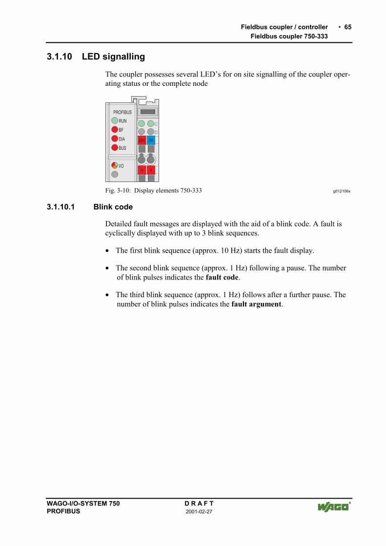
Fieldbus coupler / controller 65Fieldbus coupler 750-333
WAGO-I/O-SYSTEM 750 D R A F TPROFIBUS 2001-02-27
3.1.10 LED signalling
The coupler possesses several LEDs for on site signalling of the coupler oper-ating status or the complete node
24V 0V
+ +
RUN
BF
DIA
BUS
I/O
PROFIBUS
C
DB
A
Fig. 3-10: Display elements 750-333 g012106x
3.1.10.1 Blink code
Detailed fault messages are displayed with the aid of a blink code. A fault iscyclically displayed with up to 3 blink sequences.
• The first blink sequence (approx. 10 Hz) starts the fault display.
• The second blink sequence (approx. 1 Hz) following a pause. The numberof blink pulses indicates the fault code.
• The third blink sequence (approx. 1 Hz) follows after a further pause. Thenumber of blink pulses indicates the fault argument.

66 Fieldbus coupler / controllerFieldbus coupler 750-333
D R A F T WAGO-I/O-SYSTEM 7502001-02-27 PROFIBUS
3.1.10.2 Fieldbus status
The upper four LED´s signal the operating conditions of the PROFIBUScommunication.
LED Colour Meaning
RUN green The 'RUN' LED indicates to the user if the fieldbus coupler is per-fectly initialised.
BF red The 'BF' LED indicates that the communication functions via thePROFIBUS.
DIA red The 'DIA' LED indicates an external diagnosis.
BUS red The 'BUS' LED signals a projecting fault.
RUN BF DIA BUS Meaning
off off off off No operating voltage to the coupler (status LED ofthe bus coupler supply does not light up) or ahardware fault is present.
on on * off PROFIBUS interface started, baud rate was not yetrecognised.
on blinks * off Baud rate recognised, station not yet parameterisedand configured.
on blinks on blinkscycli-cally
Slave was incorrectly projected.Fault message via blink code
on off * off The coupler is exchanging data.
on * on * The coupler signals an existing diagnosis.
* Not relevant

Fieldbus coupler / controller 67Fieldbus coupler 750-333
WAGO-I/O-SYSTEM 750 D R A F TPROFIBUS 2001-02-27
3.1.10.3 Fault message via blink code of the BUS-LED
Fault argument Fault description
Fault code 1: Fault in parameterisation telegram
1 Insufficient parameterisation data
2 Excessive parameterisation data
Fault code 2: Fault in parameterisation telegram
n Faulty parameterised byte n
Fault code 3: Fault in configuration telegram
1 Insufficient configuration data
2 Excessive configuration data
Fault code 4: Fault in configuration telegram
n Configuration byte (module) n is faulty
Fault code 5: Fault in the data length
1 maximum input data length exceeded
2 maximum output data length exceeded
Fault code 6: Compilate buffer overflow
1 Compilate buffer overflow for DP process image

68 Fieldbus coupler / controllerFieldbus coupler 750-333
D R A F T WAGO-I/O-SYSTEM 7502001-02-27 PROFIBUS
3.1.10.4 Node status
The 'I/O' LED indicates the node operation and signals faults occurring.
I/O Meaning
green Data cycle on the internal bus
off No data cycle on the internal bus
red Coupler hardware defective
redblinks
When starting: internal bus is initialisedDuring operation: general internal bus fault
redblinks cyclically
Fault message during internal bus reset and internal fault:
orange FLASH access to bus coupler firmware
The coupler starts after switching on the supply voltage. The "I/O" LEDflashes red. Following a fault free run up the "I/O" LED changes to greensteady light.In the case of a fault the "I/O" LED continues blinking red. The fault is cycli-cally displayed with the blink code.
“I/O”-LED an
Versorgungsspannungeinschalten
Koppler-Hochlauf
“I/O”-LED blinkt
Feldbusstart
JaFehler
Nein
“I/O”-LED1. Blinksequenz(leitet opt. Anzeige eines Fehlers ein)
1. Pause
“I/O”-LED2. BlinksequenzFehlercode (Anzahl Blinkimpulse)
2. Pause
“I/O”-LED3. BlinksequenzFehlerargument (Anz. Blinkimp.)
Fig. 3-11: Signalling the LED's node status g012111d
After overcoming a fault restart the coupler by switching off and on the supplyvoltage.

Fieldbus coupler / controller 69Fieldbus coupler 750-333
WAGO-I/O-SYSTEM 750 D R A F TPROFIBUS 2001-02-27
3.1.10.5 Fault message via the blink code of the I/O LED
Fault argument Fault description
Fault code 1: Hardware and configuration fault
0 EEPROM check sum fault / check sum fault in parameter area of theflash memory
1 Overflow of the internal buffer memory for the inline code
2 Unknown data type
3 Module type of the flash program memory could not be determined /is incorrect
4 Fault during writing in the flash memory
5 Fault when deleting the FLASH memory
6 Changed I/O module configuration found after AUTORESET
7 Fault when writing in the serial EEPROM
8 Invalid firmware
Fault code 2: Fault in programmed configuration
0 Incorrect table entry
Fault code 3: Internal bus command fault
0 I/O module(s) has (have) identified internal bus command as incor-rect
Fault code 4: Internal bus data fault
0 Data fault on internal bus orInternal bus interruption on coupler
n* (n>0) Internal bus interrupted after I/O module n
Fault code 5: Register communication fault
n* Internal bus fault during register communication with the I/O modulen
Fault code 7: I/O module not supported
n* I/O module not supported at position n
* The number of blink pulses (n) indicates the position of the I/O module. I/O moduleswithout data are not counted (e.g. supply module without diagnosis)
Example: the 13th I/O module is removed.
1. The "I/O" LED generates a fault display with the first blink sequence (approx. 10 Hz).
2. The first pause is followed by the second blink sequence (approx. 1 Hz). The "I/O"LED blinks four times and thus signals the fault code 4 (internal bus data fault).
3. The third blink sequence follows the second pause. The "I/O ERR" LED blinks twelvetimes. The fault argument 12 means that the internal bus is interrupted after the 12th
I/O module.

70 Fieldbus coupler / controllerFieldbus coupler 750-333
D R A F T WAGO-I/O-SYSTEM 7502001-02-27 PROFIBUS
3.1.10.6 Supply voltage status
LED Colour Meaning
A green Status of the operating voltage system
C green Status of the operating voltage power jumper contacts
There are two green LEDs in the coupler supply section to display the supplyvoltage. The left LED (A) indicates the 24 V supply for the coupler. The righthand LED (C) signals the supply to the field side, i.e. the power jumper con-tacts.

Fieldbus coupler / controller 71Fieldbus coupler 750-333
WAGO-I/O-SYSTEM 750 D R A F TPROFIBUS 2001-02-27
3.1.11 Fault behaviour
3.1.11.1 Fieldbus failure
A fieldbus failure has occurred when the master is switched off or the bus ca-ble is interrupted. A fault in the master can also lead to a fieldbus failure.
The red "BF" LED lights up.
The failure of the fieldbus can activate the parameterisable substitute value ofthe I/O modules. During projecting of the inputs and outputs a substitute valuecan be laid down for each channel.
Substitute valuestrategy
Value (bit orientated)Digital output modules
Value (byte orientated)Analog output modules
Minimum value 0 0 or 4 mA, 0 V
Maximum value 1 20 mA, 10 V
Substitute value 0 or 1 0/4 ... 20 mA, -10 ... +10 V
Stop internal bus Behaviour determined by I/O module
The value is entered in the output process image by the coupler. With I/Omodules with byte orientated data width, e.g. the pulse width module, the sub-stitute value is determined via the value area.
As soon as the fieldbus is active the process data is transmitted and the outputcorrespondingly set in the nodes.

72 Fieldbus coupler / controllerFieldbus coupler 750-333
D R A F T WAGO-I/O-SYSTEM 7502001-02-27 PROFIBUS
3.1.11.2 Internal bus fault
An internal bus fault is created, for example, if an I/O module is removed. Ifthis fault occurs during operation the output modules behave in the same man-ner as an I/O module stop. The input process image is set in accordance withthe projected strategy.
The "I/O" LED blinks red. The slave generates a detailed fault message.
Once the internal bus fault has been overcome the coupler starts up automati-cally in accordance with the parameterised restart routine. The process datatransfer is then restarted and the outputs reset in the nodes.

Fieldbus coupler / controller 73Fieldbus coupler 750-333
WAGO-I/O-SYSTEM 750 D R A F TPROFIBUS 2001-02-27
3.1.12 Technical data
System data
Number of I/O modules 96 with repeater
Number of I/O points approx. 6000 (master dependent)
Transmission medium Cu cable in accordance with EN 50170
Bus segment length 100 m ... 1200 m(baud rate dependent / cable dependent)
Transmission rate 9.6 kBaud ... 12 MBaud
Transmission time with 10 moduleseach with 32 DI and 32 DO, 12MBaud
typically 1 msmax. 3.3 ms
Bus connection 1 x D-SUB 9; socket
Standards and approvals
UL (UL508) E175199
Standard EN 50 170
Conformity marking CE
Technical data
Number of I/O modules 63
Protocol DP / DPV1
Input process image max. 128 Byte
Output process image max. 128 Byte
Configuration via PC or controls
Voltage supply DC 24 V (-15 % / + 20 %)
Input currentmax 500 mA at 24 V
Internal system supply module effi-ciency
87 %
Internal power consumption 200 mA at 5 V
Total current for I/O modules 1800 mA at 5 V
Voltage via power jumper contacts DC 24 V (-15 % / + 20 %)
Current via power jumper contactmax DC 10 A
Dimensions (mm) B x H x T 51 x 65* x 100 (*from top edge of mounting rail)
Weight approx. 195 g
EMC interference resistance as per EN 50082-2 (95)
EMC interference transmission as per EN 50081-2 (94)

74 Fieldbus coupler / controllerFieldbus Controller 750-833
D R A F T WAGO-I/O-SYSTEM 7502001-02-27 PROFIBUS
3.2 Fieldbus Controller 750-833This chapter includes:
3.2.1 Description ......................................................................................763.2.2 Hardware .........................................................................................773.2.2.1 View .........................................................................................773.2.2.2 Device supply...........................................................................783.2.2.3 Fieldbus connection..................................................................793.2.2.4 Display elements ......................................................................803.2.2.5 Station address..........................................................................813.2.2.6 Configuration and programming interface ...............................813.2.2.7 Operating mode switch.............................................................823.2.3 Operating system.............................................................................833.2.3.1 Run-up......................................................................................833.2.3.2 PLC cycle .................................................................................833.2.4 Process image..................................................................................853.2.4.1 Local process image .................................................................853.2.4.2 Allocation of the input and output data....................................863.2.5 Configuration ..................................................................................873.2.5.1 GSD files ..................................................................................883.2.5.2 Identification bytes ...................................................................893.2.5.3 Example....................................................................................923.2.6 Parameterisation of the controllers..................................................943.2.7 Configuration of the process data channels ....................................963.2.8 Configuration and parameterisation of I/O modules.......................973.2.8.1 Digital I/O modules ..................................................................973.2.8.1.1 2 DI I/O modules ......................................................................973.2.8.1.2 4 DI I/O modules ......................................................................983.2.8.1.3 2 DI I/O modules with 1 bit diagn. per channel .......................993.2.8.1.4 2 DO I/O modules ..................................................................1003.2.8.1.5 2 DO I/O modules with 1 bit diagn. per channel....................1013.2.8.1.6 2 DO I/O modules with 2 bit diagn. per channel....................1023.2.8.1.7 4 DO I/O modules ..................................................................1033.2.8.1.8 2 DI/DO I/O module with 1 bit diagn. per channel ................1043.2.8.1.9 Potential supply modules with diagnosis ...............................1053.2.8.2 Analog I/O modules ...............................................................1063.2.8.2.1 2 AI modules ..........................................................................1063.2.8.2.2 4 AI module............................................................................1073.2.8.2.3 2 AO modules.........................................................................1083.2.8.3 Special digital modules ..........................................................1093.2.8.3.1 Counter modules ....................................................................1093.2.8.3.2 PWM module .........................................................................1103.2.8.4 Distance and Angle Messurment Modules.............................1113.2.8.4.1 SSI generator interface ...........................................................1113.2.8.4.2 Incremental encoder interface ................................................1123.2.8.4.3 Digital impulse interface ........................................................1133.2.8.5 Serial interfaces ......................................................................114

Fieldbus coupler / controller 75Fieldbus Controller 750-833
WAGO-I/O-SYSTEM 750 D R A F TPROFIBUS 2001-02-27
3.2.9 Diagnosis.......................................................................................1153.2.9.1 Stations status 1 to 3...............................................................1163.2.9.2 PROFIBUS-DP master address..............................................1163.2.9.3 Manufacturer identification....................................................1163.2.9.4 Identification based diagnosis ................................................1163.2.9.5 Device status ..........................................................................1173.2.9.5.1 Internal status messages and arguments .................................1183.2.9.5.2 Internal bus status messages and arguments ..........................1183.2.9.5.3 PROFIBUS-DP status messages and arguments....................1193.2.9.5.4 PLC-RTS status messages and arguments .............................1193.2.9.6 Channel based diagnosis ........................................................1203.2.9.6.1 Fault types of I/O modules with diagnostic capability...........1213.2.9.6.2 I/O modules fault cases ..........................................................1223.2.10 Commissioning (start-up) with WAGO-I/O-PRO ........................1233.2.11 LED signalling ..............................................................................1243.2.11.1 Blink code ..............................................................................1243.2.11.2 Fieldbus status ........................................................................1253.2.11.3 Fault message by means of blink code of the BUS-LED.......1263.2.11.4 Node status .............................................................................1273.2.11.5 Fault message via blink code from the I/O-LED....................1283.2.11.6 Supply voltage status..............................................................1293.2.12 Fault behaviour .............................................................................1293.2.12.1 Fieldbus failure.......................................................................1293.2.12.2 Internal bus fault.....................................................................1303.2.13 Technical data ...............................................................................131

76 Fieldbus coupler / controllerFieldbus Controller 750-833
D R A F T WAGO-I/O-SYSTEM 7502001-02-27 PROFIBUS
3.2.1 Description
The programmable fieldbus coupler 750-833 combines the PROFIBUS DP-functions of the fieldbus coupler 750-333 with that of a programmable logiccontrol (PLC). The application program is created with WAGO-I/O-PRO inaccordance with IEC 61131-3. The programmer has access to all fieldbus andI/O data.
• Load relief for the central controls using decentral processing units• Dividing complex applications into individual testable units• Programmable fault reaction in the case of a fieldbus system failure• Load relief of the communication system PROFIBUS DP by signal proc-
essing• Reduction of reaction times by direct access to the periphery (without hav-
ing pass through the fieldbus system PROFIBUS DP)• Autarcic smallest scale controls (station address 0)• Use for decentral and central control• Programmable in accordance with IEC 61131-3 in all 5 languages: IL, LD,
FBD, ST and SFC
In the initialisation phase the bus coupler determines the physical structure ofthe node and creates the process image of all inputs and outputs on this basis.I/O modules with a bit width of less than 8 can only be grouped to one byte ineach case in order to optimise the address space.
It is also still possible to deactivate projected I/O modules. In this manner thephysical structure of the node can be individually structured with reference toits periphery signals, without touching an already existing control application.
The diagnosis concept is based on the identification and channel based diagno-sis in accordance with EN 50170. In this manner it is not necessary to programmodules for evaluation of the manufacturer specific diagnosis information.
• Max. process data length 128 Byte (input and output process image)• Automatic recognition of the transmission speed on the PROFIBUS of
9.6 kBd to 12 MBd• All I/O modules from the WAGO-I/O-SYSTEM 750 are supported• Configuration modules can be parameterised as wildcards.• Parameterable substitute value for each channel• D-Sub 9 pole bus connection

Fieldbus coupler / controller 77Fieldbus Controller 750-833
WAGO-I/O-SYSTEM 750 D R A F TPROFIBUS 2001-02-27
3.2.2 Hardware
3.2.2.1 View
24V 0V
+ +
- -
PE PE
01 02
750
-833
RUN
BF
DIA
I/O
USR
PROFIBUS
x10123
45678
9
x100123
45678
9
ADDRESS
C
DB
A
BUS Versorgung24V0V
0V
Leistungskontakte
Status derBetriebsspannung-Leistungskontakte-System
Versorgung überLeistungskontakte24V
Datenkontakte
Feldbus-anschlussD-Sub
Adresse
Adresse
Konfigurations-und Programmier-Schnittstelle
Fig. 3-12: Fieldbus coupler 750-833 PROFIBUS DP/V1 g083300d
The controller comprises of:
• Device supply with internal system supply module for the system supply aswell as power jumper contacts for the field supply via assembled I/O mod-ules
• Fieldbus interface with the bus connection
• 2 rotary switches for the station address (decimal)
• Display elements (LED's) for status display of the operation, the bus com-munication, the operating voltages as well as for fault messages and diag-nosis
• Configuration and programming interface
• Operating mode switch
• Electronics for communication with the I/O modules (internal bus) and thefieldbus interface

78 Fieldbus coupler / controllerFieldbus Controller 750-833
D R A F T WAGO-I/O-SYSTEM 7502001-02-27 PROFIBUS
3.2.2.2 Device supply
The supply is via fed in via terminal blocks with CAGE CLAMP® connection.Device supply is intended for system supply and field side supply.
1
2
3
4
5
6
7
8
750-333
24V
10nF
24V
10nF
0V
DC
DC24V/0V
24V
0V
0V
ELEKTRONIK
Bus-klemmen
FELDBUSINTERFACE
ELEK
TR
ONIK
FELD
BU
SIN
TER
FAC
E
Fig. 3-13: Device supply g012105d
The integrated internal system supply module generates the necessary voltageto supply the electronics and the connected I/O modules.
The fieldbus interface is supplied with electrically isolated voltage from theinternal system supply module.

Fieldbus coupler / controller 79Fieldbus Controller 750-833
WAGO-I/O-SYSTEM 750 D R A F TPROFIBUS 2001-02-27
3.2.2.3 Fieldbus connection
The PROFIBUS interface is designed as a Sub-D connection in accordancewith the US Standard EIA RS 485 for cable linked data transmission.
16
7
8
9
2
3
4
5
9-pol. D-Sub-Buchse
DGND
RTS
RxD/TxD-PRxD/TxD-N
VP
Fig. 3-14: Bus connection, D-SUB g012102d
Pin Signal Description
3 RxD(TxD)-P Transmit (receive) signal
4 RTS Ready To Send
5 GND Supply ground
6 Vcc Supply voltage
8 RxD(TxD) N Transmit (receive) signal
The connection point is mechanically lowered permitting fitting in an 80 mmhigh switch box once connected

80 Fieldbus coupler / controllerFieldbus Controller 750-833
D R A F T WAGO-I/O-SYSTEM 7502001-02-27 PROFIBUS
3.2.2.4 Display elements
The operating status of the fieldbus coupler or of the node is signalled via lightdiodes (LED).
24V 0V
+ +
RUN
BF
DIA
BUS
I/O
USR
PROFIBUS
C
DB
A
Fig. 3-15: Display elements 750-833 g012107x
LED Colour Meaning
RUN green The 'RUN' LED indicates to the user whether the fieldbus coupler /controller is correctly initialised.
BF red The 'BF' LED indicates whether the communication via thePROFIBUS is functioning.
DIA red The 'DIA' LED indicates an external diagnosis. The signalling is notsupported by all devices.
BUS red The 'BUS' LED signalled a projecting fault.
IO red /green/ orange
The 'I/O' LED indicates the operation of the node an and signalsfaults occurring.
USR red /green/ orange
The 'USR' LED can be selected by a user program in a programma-ble fieldbus controller.
A green Status of the operating voltage system
C green Status of the operating voltage power jumper contact

Fieldbus coupler / controller 81Fieldbus Controller 750-833
WAGO-I/O-SYSTEM 750 D R A F TPROFIBUS 2001-02-27
3.2.2.5 Station address
The station address is determined via two decimal rotary switches on the elec-tronic module.
x100123
45678
9
ADDRESS
x10123
45678
9
Fig. 3-16: Creating the station address g012102d
The switch x1 determines the unit position of the address. The switch x10determines the tens position of the address. Valid station addresses lie between1 and 99.
The station address is taken over by the fieldbus coupler after switching on thedevice (initialisation phase). Adjustments to the switch during operation haveno effect.
NoteAfter Power-On the station address 0 causes the run-up of the controller andstart of the PLC functions, without the fieldbus being active.Using this function an autarcic small scale control can be realised using theWAGO-I/O-SYSTEM 750
3.2.2.6 Configuration and programming interface
The configuration and programming interface is located behind the cover flap.This is used to communicate with WAGO-I/O-CHECK and WAGO-I/O-PROas well as for firmware uploading.
Konfigurations- undProgrammierschnittstelle
Fig. 3-17: Configuration interface g01xx07d
The communication cable (750-920) is connected to the 4 pole male header.

82 Fieldbus coupler / controllerFieldbus Controller 750-833
D R A F T WAGO-I/O-SYSTEM 7502001-02-27 PROFIBUS
3.2.2.7 Operating mode switch
The operating mode switch is located behind the cover flap.
Betriebsartenschalter
Fig. 3-18: Operating mode switch g01xx10d
The switch is a push/slide switch with 3 settings and a hold-to-run function.
Operating mode switch Function
From middle to top position Activate program processing (RUN)
From top to middle position Stop program processing (STOP)
(Lower position, bootstrap) (For original loading of firmware,not necessary for user)
Push down(e.g with a screwdriver)
Hardware resetAll outputs and flags are reset; variables are set to 0 or toFALSE or to an initial value.
The hardware reset can be performed with STOP as wellas RUN in any position of the operating mode switch!
AttentionIf outputs are set when switching over the operating mode switch from RUNto STOP they remain set! Switching off on the software side e.g. by initiators,are ineffective, because the program is no longer processed.
(An operating mode is internally changed at the end of a PLC cycle.)
NoteWith "GET_STOP_VALUE" (library "System.lib") WAGO-I/O-PRO 32 pro-vides a function which serves to recognise the last cycle prior to a programstop giving the user the possibility to program the behaviour of the controllerin case of a STOP. With the aid of this function the controller outputs can beswitched to a safe condition.

Fieldbus coupler / controller 83Fieldbus Controller 750-833
WAGO-I/O-SYSTEM 750 D R A F TPROFIBUS 2001-02-27
3.2.3 Operating system
3.2.3.1 Run-up
The controller runs-up after switching on the supply voltage or after a hard-ware reset. The PLC program in the flash memory is transferred to the RAM.The "I/O" LED flashes orange.
The controller then checks all functions of its modules in a self test, the inter-nal bus and the fieldbus interface. Following this the I/O modules and the pre-sent configuration is determined. At the same time a list is generated which isnot visible from outside. This includes an input and an output area, whichshows on the fieldbus RAM of the fieldbus RAM. This is followed by the ini-tialisation of the system. The variables are set to 0 or to FALSE or to an ini-tialisation value given by the PLC program. The flags retain their status . The"I/O" LED blinks red during this phase.
Following a fault free run-up the controller changes over to the "Fieldbus start"mode. The "I/O" LED lights up green.
A PLC program does not yet exist in the flash memory when delivered. Thecontroller runs-up as described, without initialising the system. It then behavesas a coupler.
3.2.3.2 PLC cycle
The PLC cycle starts following a fault free run-up when the operating modeswitch is in the top position or by a start command from the WAGO-I/O-PRO32. The input and output data of the fieldbus and the I/O modules as well asthe times are read. Subsequently the PLC program in the RAM is processedfollowed by the output data of the fieldbus and the I/O modules in the processimage. Operating system functions, amongst others, for diagnosis and commu-nication are performed an the times actualised at the end of the PLC cycle. Thecycle starts again with the reading in of the input and output data and thetimes.
The change of the operating mode (STOP/RUN) is made at the end of a PLCcycle.
The cycle time is the time from the start of the PLC program to the next start.If a loop is programmed within a PLC program the PLC running time and thusthe PLC cycle are extended correspondingly.
The inputs, outputs and times are not updated during the processing of thePLC program. This actualisation occurs in a defined manner only at the end ofthe PLC program. For this reason it is not possible to wait for an event fromthe process or the elapse of a time within a loop.

84 Fieldbus coupler / controllerFieldbus Controller 750-833
D R A F T WAGO-I/O-SYSTEM 7502001-02-27 PROFIBUS
Feldbusdaten,Busklemmendaten
Ein-/Ausgänge u. Zeiten lesen
Controller-Selbsttest,Ermittlung Busklemmen
und Konfiguration,Erstellung interner Liste
Feldbusdaten,Busklemmendaten
Versorgungsspannungeinschalten oderHardware-Reset
Ja
SPS-Programmim Flash-Speicher
SPS-Programmvom Flash-Speicherins RAM übertragen
Im RAM vorhandenesSPS-Programm
bearbeiten
Ausgänge schreiben
Betriebssystem-Funktionen,Zeiten aktualisieren
“I/O”-LEDgrün an
“I/O”-LEDblinkt
rot
“I/O”-LEDblinkt
orange
SPS-Zyklus
JaFehler
RUN
Initialisierung des Systems
Nein
STOPBetriebsart
RUN
Betriebsartenschalter:oberer Stellung oderWAGO-I/O- 32:‘Online’ ‘Start’/’Stop’
PRO
STOP
Variablen auf 0 bzw. FALSEoder auf Initialwert setzen,Merker behalten ihrenZustand bei
Betriebsart
Nein
STOP
JaFehler
Nein
Betriebsartenschalter:StellungswechselWAGO-I/O- 32:‘Online’ ‘Start’/’Stop’
PRO
FeldbusstartBetrieb als Koppler
Controller-Selbsttest,Ermittlung Busklemmen
und Konfiguration,Erstellung interner Liste
Fig. 3-19: Controller operating system g012112d

Fieldbus coupler / controller 85Fieldbus Controller 750-833
WAGO-I/O-SYSTEM 750 D R A F TPROFIBUS 2001-02-27
3.2.4 Process image
3.2.4.1 Local process image
After switching on the controller recognises all I/O modules connected in thenode, which are waiting for or transmitting data (data width/bit width > 0). Innodes analog and digital I/O modules can be fitted mixed.
NoteFor the number of input and output bits or bytes of the individual switched onI/O modules please refer to the corresponding description of the I/O modules.
The controller generates an internal local process image from the data widthand the type of I/O module as well as the position of the I/O modules in thenode. This is divided into an input and an output area.
The data of the digital I/O modules are bit orientated, i.e. the data exchange ismade bit by bit. The analog I/O modules are representative for all I/O moduleswhich are byte orientated, in which the data exchange is also made byte bybyte. These I/O modules also include, for example, counter modules, I/O mod-ules for angle and path measurement as well as communication modules.
The data of the I/O modules is separated for the local input and output processimage in the sequence of their position after the controller in the individualprocess image.
NoteIf a node is changed or extended this may result in a new process imagestructure. In this case the process data addresses also change in comparisonwith earlier versions.

86 Fieldbus coupler / controllerFieldbus Controller 750-833
D R A F T WAGO-I/O-SYSTEM 7502001-02-27 PROFIBUS
3.2.4.2 Allocation of the input and output data
The process data is exchanged via the PROFIBUS with the higher rankingcontrols (Master). A maximum of 128 byte of data is transmitted from themaster to the controller, or node to the output data. The controller returns amaximum of 128 byte input data as a reply to the master.
The modules are configured when projecting the nodes. These modules can becopied from a hardware catalogue by the configurations programs. The infor-mation covering the possible modules is saved in the GSD files.
The controller generates an internal mapping in accordance with the installedand configured settings of the node, in which the allocation of the input andoutput data is determined in the local process image with the position in thePROFIBUS DP Telegram.
402
DI
402 452 452 504 504 550 550 600
1 2 3 4 5 6 7 8 9750-DI AIAI DODO AOAO
PROFIBUS
PROFIBUS
I I
OO
I
OO
I
I
O
AnschaltungCPU
bit- und byteweiseZuordnung,
Erstellung automatischdurch den Koppler
byteweise Zuordnung,Erstellung auf dem PC
ZuordnungslisteZuordnungsliste
Master, z. B. SPS
Master-Adressen
Fig. 3-20: Allocation of the input and output data g012117d

Fieldbus coupler / controller 87Fieldbus Controller 750-833
WAGO-I/O-SYSTEM 750 D R A F TPROFIBUS 2001-02-27
3.2.5 Configuration
The configuration of the node is performed in accordance with the physical re-quirements of the fieldbus controllers and I/O modules.
The fieldbus controller or the process data channel is to be configured on thefirst slot.The other slots are configured in accordance with the physical requirements ofthe I/O modules, whereby only I/O modules with process data are relevant.The supply modules without diagnosis, the supply modules without diagnosis,the bus internal system supply module and the termination module are to beignored during configuration, as they do not provide any process data.
2 or 3 modules per I/O module are entered in the hardware catalogue. Themodules appear as750-xyz ..., e.g. 750-400 2 DI/24 V DC/3.0 ms. andPFC 750-xyz ..., e.g.. PFC 750-400 2 DI/24 V DC/3.0 ms.The identification PFC 750-xyz ... states that the module concerned is exclu-sively processed by the internal control application. Its process data is nottransmitted via the PROFIBUS-DP to the master or to the higher ranking con-trols.
Alos the entry *750-xyz .... is listed for all binary modules. When using thisidentification the controller adds the binary information of the current modulein a byte previously opened with 750-xyz .... The use of a * module is onlypermitted when the number of channels is less or identical to the remainingbits in the previously opened byte. The binary I/O modules combined in a bytemay be at different locations, i.e. binary I/O modules of a different signal typeor byte orientated I/O modules can be connected between.
In order to configure the scope of the connected peripheries individually andindependent of the control program, it is possible to parameter the I/O modulesin the configuration table as not plug fitted. In this manner the process datastill on the PROFIBUS DP can be filtered for the individual module and nottransmitted to the periphery or read by it.
With the 750-833, after configuration of the connected periphery, the memoryarea is configured due to the variable arrangement of the fieldbus variables.For this the identification1 byte PFC outputs, 2 byte PFC outputs to 64 byte PFC outputsis available for the input image as well as1 byte PFC inputs, 2 byte PFC inputs to 64 byte PFC inputsfor the output image.
By optionally combining the existing modules it is possible to project the re-quired length on the fieldbus variables for PROFIBUS-DP.

88 Fieldbus coupler / controllerFieldbus Controller 750-833
D R A F T WAGO-I/O-SYSTEM 7502001-02-27 PROFIBUS
3.2.5.1 GSD files
Under PROFIBUS DP the power features of the devices are defined by themanufacturer in the form of a GSD file (device master data) and made avail-able to the user.
Structure, content and coding of this device master data are standardised sothat projecting with any DP slaves with projecting data from various manu-facturers is possible.
iFurther informationThe PNO provides information about the GSD files of all listed manufactur-ers.
GSD and symbol files for the configuration of the I/O modules are availableunder the order number 750-910 on disk or from the WAGO INTERNETpage.
http://www.wago.com
GSD file for I/O module 750-833 WAGOB756.GSD
The GSD file is read by the configuration software and the corresponding set-tings transferred. For the necessary entries and handling steps please refer tothe software user manuals.

Fieldbus coupler / controller 89Fieldbus Controller 750-833
WAGO-I/O-SYSTEM 750 D R A F TPROFIBUS 2001-02-27
3.2.5.2 Identification bytes
The identification bytes contain information about the structure and the scopeof the inputs and outputs of the devices. For projecting each I/O module oreach channel is allocated an identification (module).
Bit Meaning
7 6 5 4 3 2 1 0
000...1
000...1
001...1
010...1
Data length1 byte or word2 bytes or words3 bytes or words...16 bytes or 16 words
0011
0101
Input and outputSpec. identification formatsInputOutputInput and output
01
Format0 = Byte structure1 = Word structure
01
Consistency aboutByte or wordTotal length
For the special identification byte (Bit 4 and 5 = 00) is defined:
Bit Meaning
7 6 5 4 3 2 1 0
00...11
00...11
00...11
01...01
Length of the manufacturer specific data0 = no manufacturer specific data
1 ... 14 = Length of the manufacturer specific data
15 = no manufacturer specific data follows
0 0Input and outputSpec. identification formats
0011
0101
Input and outputunassigned slota length byte for inputs followsa length byte for outputs followsa length byte for inputs and outputs follows
Structure of the length byte:
Bit Meaning
7 6 5 4 3 2 1 0
0...1
0...1
0...1
0...1
1...1
0...1
Data length1 byte or word...63 bytes or 63 words
01
Format0 = Byte structur1 = Word structur
01
Consistency aboutByte or wordTotal length

90 Fieldbus coupler / controllerFieldbus Controller 750-833
D R A F T WAGO-I/O-SYSTEM 7502001-02-27 PROFIBUS
This information is saved in the GSD file. For projecting the I/O module isselected in accordance with the article number using the configuration soft-ware contained in the hardware catalogue of the I/O module.
Module Ident. Module Ident. Module Ident.
750-833 No process data channel 0x00750-833 2 byte process datachannel
0xB1
750-400 2 DI/24 V DC/3.0 ms 0x10 *750-400 2 DI/24 V DC/3.0 ms 0x00 PFC 750-400 2 DI/24 V DC/3.0 ms 0x00750-401 2 DI/24 V DC/0.2 ms 0x10 *750-401 2 DI/24 V DC/0.2 ms 0x00 PFC 750-401 2 DI/24 V DC/0.2 ms 0x00750-402 4 DI/24 V DC/3.0 ms 0x10 *750-402 4 DI/24 V DC/3.0 ms 0x00 PFC 750-402 4 DI/24 V DC/3.0 ms 0x00750-403 4 DI/24 V DC/0.2 ms 0x10 *750-403 4 DI/24 V DC/0.2 ms 0x00 PFC 750-403 4 DI/24 V DC/0.2 ms 0x00750-404 Counter Module 0xF2 PFC 750-404 Counter Module 0x00750-405 2 DI/230 V AC/10 ms 0x10 *750-405 2 DI/230 V AC/10 ms 0x00 PFC 750-405 2 DI/230 V AC/10 ms 0x00750-406 2 DI/120 V AC/10 ms 0x10 *750-406 2 DI/120 V AC/10 ms 0x00 PFC 750-406 2 DI/120 V AC/10 ms 0x00750-408 4 DI/24 V DC/3.0 ms 0x10 *750-408 4 DI/24 V DC/3.0 ms 0x00 PFC 750-408 4 DI/24 V DC/3.0 ms 0x00750-409 4 DI/24 V DC/0.2 ms 0x10 *750-409 4 DI/24 V DC/0.2 ms 0x00 PFC 750-409 4 DI/24 V DC/0.2 ms 0x00750-410 2 DI/24 V DC/3.0 ms 0x10 *750-410 2 DI/24 V DC/3.0 ms 0x00 PFC 750-410 2 DI/24 V DC/3.0 ms 0x00750-411 2 DI/24 V DC/0.2 ms 0x10 *750-411 2 DI/24 V DC/0.2 ms 0x00 PFC 750-411 2 DI/24 V DC/0.2 ms 0x00750-412 2 DI/48 V DC/3.0 ms 0x10 *750-412 2 DI/48 V DC/3.0 ms 0x00 PFC 750-412 2 DI/48 V DC/3.0 ms 0x00750-413 2 DI/48 V DC/0.2 ms 0x10 *750-413 2 DI/48 V DC/0.2 ms 0x00 PFC 750-413 2 DI/48 V DC/0.2 ms 0x00750-414 4 DI/5 V DC/0.2 ms 0x10 *750-414 4 DI/5 V DC/0.2 ms 0x00 PFC 750-414 4 DI/5 V DC/0.2 ms 0x00750-415 4 DI/24 V AC/DC/20 ms 0x10 *750-415 4 DI/24 V AC/DC/20 ms 0x00 PFC 750-415 4 DI/24 V
AC/DC/20ms 0x00
750-418 2 DI/24 V DC DIA ACK 0x30 *750-418 2 DI/24 V DC DIA ACK 0x00 PFC 750-418 2 DI/24 V DC DIAACK
0x00
750-419 2 DI/24 V DC DIA 0x10 *750-419 2 DI/24 V DC DIA 0x00 PFC 750-419 2 DI/24 V DC DIA 0x00750-423 4 DI/24 V AC/DC/50 ms 0x10 *750-423 4 DI/24 V AC/DC/50 ms 0x00 PFC 750-423 4 DI/24 V
AC/DC/50ms 0x00
750-424 2 DI/24 V DC DIA 0x10 *750-424 2 DI/24 V DC DIA 0x00 PFC 750-424 2 DI/24 V DC DIA 0x00750-452 2 AI/0-20 mA/diff. 0x51 PFC 750-452 2 AI/0-20 mA/diff. 0x00750-454 2 AI/4-20 mA/diff. 0x51 PFC 750-454 2 AI/4-20 mA/diff. 0x00750-456 2 AI/±10 V/diff. 0x51 PFC 750-456 2 AI/±10 V/diff. 0x00750-461 2 AI/RTD 0x51 PFC 750-461 2 AI/RTD 0x00750-462 2 AI/TC 0x51 PFC 750-462 2 AI/TC 0x00750-465 2 AI/0-20 mA/SE 0x51 PFC 750-465 2 AI/0-20 mA/SE 0x00750-466 2 AI/4-20 mA/SE 0x51 PFC 750-466 2 AI/4-20 mA/SE 0x00750-467 2 AI/0-10 V/SE 0x51 PFC 750-467 2 AI/0-10 V/SE 0x00750-468 4 AI/0-10 V/SE 0x53 PFC 750-468 4 AI/0-10 V/SE 0x00750-469 2 AI/TC/OCM 0x51 PFC 750-469 2 AI/TC/OCM 0x00750-472 2 AI/0-20 mA/OVLP 0x51 PFC 750-472 2 AI/0-20 mA/OVLP 0x00750-474 2 AI/4-20 mA/OVLP 0x51 PFC 750-474 2 AI/4-20 mA/OVLP 0x00750-476 2 AI/±10 V 0x51 PFC 750-476 2 AI/±10 V 0x00750-478 2 AI/0-10 V 0x51 PFC 750-478 2 AI/0-10 V 0x00750-501 2 DO/24 V DC/0.5 A 0x20 *750-501 2 DO/24 V DC/0.5 A 0x00 PFC 750-501 2 DO/24 V DC/0.5 A 0x00750-502 2 DO/24 V DC/2.0 A 0x20 *750-502 2 DO/24 V DC/2.0 A 0x00 PFC 750-502 2 DO/24 V DC/2.0 A 0x00750-504 4 DO/24 V DC/0.5 A 0x20 *750-504 4 DO/24 V DC/0.5 A 0x00 PFC 750-504 4 DO/24 V DC/0.5 A 0x00750-506 2 DO/24 V DC/0.5 A DIA 0x20 *750-506 2 DO/24 V DC/0.5 A DIA 0x00 PFC 750-506 2 DO/24 V DC/0.5 A 0x00750-507 2 DO/24 V DC/2.0 A DIA 0x20 *750-507 2 DO/24 V DC/2.0 A DIA 0x00 PFC 750-507 2 DO/24 V DC/2.0 A 0x00750-509 2 DO/230 V AC/0.3 A 0x20 *750-509 2 DO/230 V AC/0.3 A 0x00 PFC 750-509 2 DO/230 V AC/0.3 A 0x00750-511 2 DO 24 V DC/PWM 0xF2 PFC 750-511 2 DO 24 V DC/PWM 0x00750-512 2 DO Relay/250 V AC 0x20 *750-512 2 DO Relay/250 V AC 0x00 PFC 750-512 2 DO Relay/250 V AC 0x00750-513 2 DO Relay/250 V AC 0x20 *750-513 2 DO Relay/250 V AC 0x00 PFC 750-513 2 DO Relay/250 V AC 0x00750-514 2 DO Relay/125 V AC 0x20 *750-514 2 DO Relay/125 V AC 0x00 PFC 750-514 2 DO Relay/125 V AC 0x00750-516 4 DO/24 V DC/0.5 A 0x20 *750-516 4 DO/24 V DC/0.5 A 0x00 PFC 750-516 4 DO/24 V DC/0.5 A 0x00750-517 2 DO Relay/230 V AC 0x20 *750-517 2 DO Relay/230 V AC 0x00 PFC 750-517 2 DO Relay/230 V AC 0x00750-519 4 DO/5 V DC/20 mA 0x20 *750-519 4 DO/5 V DC/20 mA 0x00 PFC 750-519 4 DO/5 V DC/20 mA 0x00750-522 2 DO/230V AC/0.5 ADIA
0x20 *750-522 2 DO/230V AC/0.5 ADIA
0x00 PFC 750-522 2 DO/230V DC/0.5 A 0x00
750-550 2 AO/0-10 V 0x61 PFC 750-550 2 AO/0-10 V 0x00750-552 2 AO/0-20 mA 0x61 PFC 750-552 2 AO/0-20 mA 0x00750-554 2 AO/4-20 mA 0x61 PFC 750-554 2 AO/4-20 mA 0x00750-556 2 AO/±10 V 0x61 PFC 750-556 2 AO/±10 V 0x00750-610 P supply. 24 V DC/DIA 0x00750-611 P supply. 230 V AC/DIA 0x00750-630 SSI-Intf. Standard 0x95 750-630 SSI-Intf. alternative 0x93 PFC 750-630 SS intf. 0x00750-631 Encoder intf. 0xB5 PFC 750-631 Encoder intf. 0x00750-650 RS232C-Intf. 5 Byte 0xB5 750-650 RS232C-Intf. 3 Byte 0xB3 PFC 750-650 RS232C intf. 0x00750-651 TTY-Intf. 5 Byte 0xB5 750-651 TTY-Intf. 3 Byte 0xB3 PFC 750-651 TTY-Intf. 0x00750-653 RS485-Intf. 5 Byte 0xB5 750-653 RS485 intf. 3 Byte 0xB3 PFC 750-653 RS485- intf. 0x00750-654 Data exch. module 0xF1 PFC 750-654 Data exch. module 0x00
1 Byte PFC-input 0xA0 2 Byte PFC inputs 0xA1 3 Byte PFC inputs 0xA24 Byte PFC inputs 0xA3 5 Byte PFC inputs 0xA4 6 Byte PFC inputs 0xA57 Byte PFC inputs 0xA6 8 Byte PFC inputs 0xA7 9 Byte PFC inputs 0xA8

Fieldbus coupler / controller 91Fieldbus Controller 750-833
WAGO-I/O-SYSTEM 750 D R A F TPROFIBUS 2001-02-27
Module Ident. Module Ident. Module Ident.
10 Byte PFC inputs 0xA9 11 Byte PFC inputs 0xAA 12 Byte PFC inputs 0xAB13 Byte PFC inputs 0xAC 14 Byte PFC inputs 0xAD 15 Byte PFC inputs 0xAE16 Byte PFC inputs 0xAF 17 Byte PFC inputs 0x80 , 0x90 18 Byte PFC inputs 0x80 , 0x9119 Byte PFC inputs 0x80 , 0x92 20 Byte PFC inputs 0x80 , 0x93 21 Byte PFC inputs 0x80 , 0x9422 Byte PFC inputs 0x80 , 0x95 23 Byte PFC inputs 0x80 , 0x96 24 Byte PFC inputs 0x80 , 0x9725 Byte PFC inputs 0x80 , 0x98 26 Byte PFC inputs 0x80 , 0x99 27 Byte PFC inputs 0x80 , 0x9A28 Byte PFC inputs 0x80 , 0x9B 29 Byte PFC inputs 0x80 , 0x9C 30 Byte PFC inputs 0x80 , 0x9D31 Byte PFC inputs 0x80 , 0x9E 32 byte PFC inputs 0x80 , 0x9F 33 Byte PFC inputs 0x80 , 0xA034 Byte PFC inputs 0x80 , 0xA1 35 Byte PFC inputs 0x80 , 0xA2 36 Byte PFC inputs 0x80 , 0xA337 Byte PFC inputs 0x80 , 0xA4 38 Byte PFC inputs 0x80 , 0xA5 39 Byte PFC inputs 0x80 , 0xA640 Byte PFC inputs 0x80 , 0xA7 41 Byte PFC inputs 0x80 , 0xA8 42 Byte PFC inputs 0x80 , 0xA943 Byte PFC inputs 0x80 , 0xAA 44 Byte PFC inputs 0x80 , 0xAB 45 Byte PFC inputs 0x80 , 0xAC46 Byte PFC inputs 0x80 , 0xAD 47 Byte PFC inputs 0x80 , 0xAE 48 Byte PFC inputs 0x80 , 0xAF49 Byte PFC inputs 0x80 , 0xB0 50 Byte PFC inputs 0x80 , 0xB1 51 Byte PFC inputs 0x80 , 0xB252 Byte PFC inputs 0x80 , 0xB3 53 Byte PFC inputs 0x80 , 0xB4 54 Byte PFC inputs 0x80 , 0xB555 Byte PFC inputs 0x80 , 0xB6 56 Byte PFC inputs 0x80 , 0xB7 57 Byte PFC inputs 0x80 , 0xB858 Byte PFC inputs 0x80 , 0xB9 59 Byte PFC inputs 0x80 , 0xBA 60 Byte PFC inputs 0x80 , 0xBB61 Byte PFC inputs 0x80 , 0xBC 62 Byte PFC inputs 0x80 , 0xBD 63 Byte PFC inputs 0x80 , 0xBE64 Byte PFC inputs 0x80 , 0xBF
1 Byte PFC outputs 0x90 2 Byte PFC outputs 0x91 3 Byte PFC outputs 0x924 Byte PFC outputs 0x93 5 Byte PFC outputs 0x94 6 Byte PFC outputs 0x957 Byte PFC outputs 0x96 8 Byte PFC outputs 0x97 9 Byte PFC outputs 0x9810 Byte PFC outputs 0x99 11 Byte PFC outputs 0x9A 12 Byte PFC outputs 0x9B13 Byte PFC outputs 0x9C 14 Byte PFC outputs 0x9D 15 Byte PFC outputs 0x9E16 Byte PFC outputs 0x9F 17 Byte PFC outputs 0x40 , 0x90 18 Byte PFC outputs 0x40 , 0x9119 Byte PFC outputs 0x40 , 0x92 20 Byte PFC outputs 0x40 , 0x93 21 Byte PFC outputs 0x40 , 0x9422 Byte PFC outputs 0x40 , 0x95 23 Byte PFC outputs 0x40 , 0x96 24 Byte PFC outputs 0x40 , 0x9725 Byte PFC outputs 0x40 , 0x98 26 Byte PFC outputs 0x40 , 0x99 27 Byte PFC outputs 0x40 , 0x9A28 Byte PFC outputs 0x40 , 0x9B 29 Byte PFC outputs 0x40 , 0x9C 30 Byte PFC outputs 0x40 , 0x9D31 Byte PFC outputs 0x40 , 0x9E 32 Byte PFC outputs 0x40 , 0x9F 33 Byte PFC outputs 0x40 , 0xA034 Byte PFC outputs 0x40 , 0xA1 35 Byte PFC outputs 0x40 , 0xA2 36 Byte PFC outputs 0x40 , 0xA337 Byte PFC outputs 0x40 , 0xA4 38 Byte PFC outputs 0x40 , 0xA5 39 Byte PFC outputs 0x40 , 0xA640 Byte PFC outputs 0x40 , 0xA7 41 Byte PFC outputs 0x40 , 0xA8 42 Byte PFC outputs 0x40 , 0xA943 Byte PFC outputs 0x40 , 0xAA 44 Byte PFC outputs 0x40 , 0xAB 45 Byte PFC outputs 0x40 , 0xAC46 Byte PFC outputs 0x40 , 0xAD 47 Byte PFC outputs 0x40 , 0xAE 48 Byte PFC outputs 0x40 , 0xAF49 Byte PFC outputs 0x40 , 0xB0 50 Byte PFC outputs 0x40 , 0xB1 51 Byte PFC outputs 0x40 , 0xB252 Byte PFC outputs 0x40 , 0xB3 53 Byte PFC outputs 0x40 , 0xB4 54 Byte PFC outputs 0x40 , 0xB555 Byte PFC outputs 0x40 , 0xB6 56 Byte PFC outputs 0x40 , 0xB7 57 Byte PFC outputs 0x40 , 0xB858 Byte PFC outputs 0x40 , 0xB9 59 Byte PFC outputs 0x40 , 0xBA 60 Byte PFC outputs 0x40 , 0xBB61 Byte PFC outputs 0x40 , 0xBC 62 Byte PFC outputs 0x40 , 0xBD 63 Byte PFC outputs 0x40 , 0xBE64 Byte PFC outputs 0x40 , 0xBF

92 Fieldbus coupler / controllerFieldbus Controller 750-833
D R A F T WAGO-I/O-SYSTEM 7502001-02-27 PROFIBUS
3.2.5.3 Example
A fieldbus node with a controller and 17 I/O modules should make the ar-rangement clear.
402
DI DI DI DI DI DI
402 402 452 602 504 504 504504 504 602602 600550 550452 452 504
1 2 3 4 5 6 7 8 9 10 11 12 13 14 15 16 17
PROFIBUS
AI AI DO DODO DO DO DO DO DODO DO DO DO AO AO AI AI AO AO AI AI DO DO
75
0-3
33
Fig. 3-21: Example application g012115x
I/O modules PI Master *No. ModulIdentification Inputs Outputs
Digital input 750-402 4 DI/24 V DC/3.0 ms EB12.0
Digital input 0x10 EB12.1
Digital input EB12.2
1
Digital input EB12.3
Digital input *750-402 4 DI/24 V DC/3.0 ms EB12.4
Digital input 0x00 EB12.5
Digital input EB12.6
2
Digital input EB12.7
Digital input 750-402 4 DI/24 V DC/3.0 ms EB13.0
Digital input 0x10 EB13.1
Digital input EB13.2
3
Digital input EB13.3
Analog input 750-452 2 AI/0-20 mA/diff. EW04
Analog input 0x51 EW2
5 Potential supply Potential supply --- ---
Digital output 750-504 4 DO/24 V DC/0.5 A AB8.0
Digital output 0x20 AB8.1
Digital output AB8.2
6
Digital output AB8.3
Digital output *750-504 4 DO/24 V DC/0.5 A AB8.4
Digital output 0x00 AB8.5
Digital output AB8.6
7
Digital output AB8.7

Fieldbus coupler / controller 93Fieldbus Controller 750-833
WAGO-I/O-SYSTEM 750 D R A F TPROFIBUS 2001-02-27
Digital output 750-504 4 DO/24 V DC/0.5 A AB9.0
Digital output 0x20 AB9.1
Digital output AB9.2
8
Digital output AB9.3
Digital output *750-504 4 DO/24 V DC/0.5 A AB9.4
Digital output 0x00 AB9.5
Digital output AB9.6
9
Digital output AB9.7
10 Potential supply Potential supply --- ---
Analog output 750-550 2 AO/0-10 V AW011
Analog output 0x61 AW2
Analog input 750-452 2 AI/0-20 mA/diff. EW412
Analog input 0x51 EW6
Analog output 750-550 2 AO/0-10 V AW413
Analog output 0x61 AW6
Analog input 750-452 2 AI/0-20 mA/diff. EW814
Analog input 0x51 EW10
15 Potential supply Potential supply --- ---
Digital output 750-504 4 DO/24 V DC/0.5 A AB10.0
Digital output 0x20 AB10.1
Digital output AB10.2
16
Digital output AB10.3
17 End module End module --- ---
* The master addresses listed in the table correspond to the allocation of the process datagiven in the master configuration.

94 Fieldbus coupler / controllerFieldbus Controller 750-833
D R A F T WAGO-I/O-SYSTEM 7502001-02-27 PROFIBUS
3.2.6 Parameterisation of the controllers
Before a data exchange can be performed between master and slave, a param-eterisation is required in addition to configuration.
The extended parameters (Extended User_Prm_Data) are provided via theGSD files as selectable text in the configuration programs.
Description Value MeaningRestart the internal bus after afault
Restart of the terminal bus following a fault,such as, for example, no termination module
POWER ON RESET*) following an interruption of the supplyAUTORESET immediately after overcoming the internal bus
faultI/O module diagnosis The diagnosis information of all I/O modules
with a diagnosis capability, for which thediagnosis is released are
released*) transferred to PROFIBUS-DP master,locked not transferred to PROFIBUS-DP master
Process value display Word or double word oriented process data, istransferred to PROFIBUS-DP master in:
INTEL Little Endian FormatMOTOROLA*) Big Endian Format
Behaviour in case of aPROFIBUS DP fault
In the case of a malfunction of thePROFIBUS DP communication the status of theconnected output periphery can be influenced invarious ways:
Stop internal bus transmis-sion
The process data exchange on the internal bus isstopped, all outputs drop out after a modulespecific monitoring time of 100 ms
Set output image to zero all outputs are immediately resetFreeze output image all outputs maintain the last status before the
malfunctionWrite substitute value*) all outputs switch a parameterisable substitute
valuePFC fault strategy PFC takes over the control via the output image
Reaction to an internal bus fault In the event of a malfunction of an internalcommunication between fieldbus controller andI/O modules, such as, for example no termina-tion module,
Stop PROFIBUS dataexchange*)
the data exchange with the PROFIBUS masteris stopped.
Set input image to zero the input information is set to zero
Freeze input image the input information prevailing before the faultis maintained
*) Default settings

Fieldbus coupler / controller 95Fieldbus Controller 750-833
WAGO-I/O-SYSTEM 750 D R A F TPROFIBUS 2001-02-27
The complete data block encompasses 34 parameterised bytes. The first 10bytes are laid down via the DP and DPV1 standard. The others receive manu-facturer specific parameters.
Byte No. Bit No. Value Meaning
Standard parameters0 0-7 Station status (see EN 50170)1 0-7 2-255 Watchdog factor 12 0-7 2-255 Watchdog factor 2
Watchdog:The response monitoring is the result ofWatchdog_Factor_1 x Watchdog_Factor_2 x 10 ms (1 ms)
3 0-7 11-255 Min TSDR,Earliest time in TBit after which the slave can reply
4 0-7 183, 0xB7 Manufacturer Identification (high byte)5 0-7 86, 0x56 Manufacturer Identification (low byte)6 0-7 Group membership,
Broad and multicast telegrams (SYNC, FREEZE)7 0-7 DPV1 status 1 (see EN 50170)8 0-7 DPV1 status 2 (see EN 50170)9 0-7 DPV1 status 3 (see EN 50170)Manufacturer parameters10 0-7 0 Table 0, register 0 LB, reserved11 0-7 0 Table 0, register 0 HB, reserved12 0-7 0 Table 0, register 1 LB, reserved13 0-7 0 Table 0, register 1 HB, reserved14 Table 0, register 2 LB
0 0 Device diagnosis locked0 1*) Device diagnosis released1 0 Internal bus restart after fault: POWER-ON-RESET1 1*) Internal bus restart after fault: AUTORESET2-7 0 reserved
15 0-7 0 Table 0, register 2 HB, reserved16 Table 0, register 3 LB
0-2 '011' reserved3 0 Data format byte orientated I/O modules: INTEL3 1*) Data format byte orientated I/O modules: MOTOROLA4-7 '1100' reserved
17 Table 0, register 3 HB0-2 Reaction to fieldbus fault:
'000''001''010''011' *)
'100''101''110''111'
- Stop internal bus transmission- Set output image to zero- Freeze output image- Write substitute values- PFC fault strategy- Not possible- Not possible- Not possible
3-5 Reaction to internal bus fault:'000' *)
'001''010''011''100''101''110''111'
- Exit data exchange- Set input image to zero- Freeze input image- Not possible- Not possible- Not possible- Not possible- Not possible
6-7 '00' reserved18 0-7 '1100.0011' Table 0, register 4 LB, reserved19 0-7 '0111.1111' Table 0, register 4 HB, reserved20 0-7 '0000.0000' Table 100, register 0 LB, reserved21 0-7 '0000.0001' Table 100, register 0 HB, reserved22 0-7 '0000.0000' Table 100, register 1 LB, reserved23 0-7 '0000.0000' Table 100, register 1 HB, reserved24 0-7 '0000.0000' Table 100, register 2 LB, reserved25 0-7 '0000.0000' Table 100, register 2 HB, reserved

96 Fieldbus coupler / controllerFieldbus Controller 750-833
D R A F T WAGO-I/O-SYSTEM 7502001-02-27 PROFIBUS
3.2.7 Configuration of the process data channels
The process data channels serve the communication between the WAGO-I/O-PRO and the running time system of the fieldbus controller. If this channel isnot required it can be projected with a process data length of zero(750-833 No process data channel).
Module Identificationhex
Identificationdec
750-833 no process data channel750-833 2 byte process data channel
0x000xB1
0177
NoteConfigure the module 750-833 2 byte process data channel or750-833 No process data channel as 1st module.

Fieldbus coupler / controller 97Fieldbus Controller 750-833
WAGO-I/O-SYSTEM 750 D R A F TPROFIBUS 2001-02-27
3.2.8 Configuration and parameterisation of I/O modules
3.2.8.1 Digital I/O modules
All binary I/O modules contain 3 bytes of extended parameterisation informa-tion, which serve, amongst others, for the identification of the internal bus andthe structure of the mapping table. For modules capable of diagnosis the diag-nosis message can be suppressed or released channel for channel or module formodule. Binary outputs offer the possibility to switch parameterisable substi-tute values in the case of a master failure.
NoteFor simplification only the article numbers are shown as module designationin the table. The module 750-400 thus corresponds to the module 750-4002 DI/24 V DC/3.0 ms
3.2.8.1.1 2 DI I/O modules
Module Identificationhex
Identificationdec
750-400, 750-401, 750-405, 750-406, 750-410,750-411, 750-412
0x10 16
*750-400, *750-401, *750-405, *750-406, *750-410, *750-411, *750-412
0x00 0
Parameter Value MeaningI/O module is physically The I/O module process data is:
plug fitted*) - supplied by the I/O modulenot plug fitted - set to zero by the controller
*) Default setting
ParameterOffset Information0 7 6 5 4 3 2 1 0
0 PFC Plug 0 0 0 0 01 7 6 5 4 3 2 1 0
0 0 0 0 0 0 0 12 7 6 5 4 3 2 1 0
0 0 0 0 0 0 0 0
PFC6 01
Module is mapped in the fieldbus and PFC-PIModule is exclusively mapped in the PFC-PI
Plug5 01
Module is physically not presentModule is physically present (default)
Italic Cannot be changed

98 Fieldbus coupler / controllerFieldbus Controller 750-833
D R A F T WAGO-I/O-SYSTEM 7502001-02-27 PROFIBUS
3.2.8.1.2 4 DI I/O modules
Module Identificationhex
Identificationdec
750-402, 750-403, 750-408, 750-409, 750-414,750-415, 750-423, 750-422, 750-424
0x10 16
*750-402, *750-403, *750-408, *750-409, *750-414,*750-415, *750-423, *750-422, *750-424
0x00 0
Parameter Value MeaningI/O module is physically The I/O module process data is:
plug fitted*) - supplied by the I/O modulenot plug fitted - set to zero by the controller
*) Default setting
ParameterOffset Information0 7 6 5 4 3 2 1 0
0 PFC Plug 0 0 0 0 11 7 6 5 4 3 2 1 0
0 0 0 0 0 0 0 12 7 6 5 4 3 2 1 0
0 0 0 0 0 0 0 0
PFC6 01
Module is mapped in the fieldbus and PFC-PIModule is exclusively mapped in the PFC-PI
Plug5 01
Module is physically not presentModule is physically present (default)
Italic Cannot be changed

Fieldbus coupler / controller 99Fieldbus Controller 750-833
WAGO-I/O-SYSTEM 750 D R A F TPROFIBUS 2001-02-27
3.2.8.1.3 2 DI I/O modules with 1 bit diagn. per channel
Module Identificationhex
Identificationdec
750-419, 750-425 0x10 16*750-419, *750-425 0x00 0
Parameter Value MeaningI/O module is physically The I/O module process data is:
plug fitted*) - supplied by the I/O modulenot plug fitted - set to zero by the controller
Diagnosis channel x The diagnosis information of the correspondingchannel is
released - transmitted to PROFIBUS-DP masterlocked*) - not transmitted to PROFIBUS-DP master
*) Default setting
ParameterOffset Information0 7 6 5 4 3 2 1 0
0 PFC Plug 0 DiagEn1
DiagEn0
0 1
1 7 6 5 4 3 2 1 0
0 0 0 0 0 1 0 12 7 6 5 4 3 2 1 0
0 0 0 0 0 0 0 0
PFC6 01
Module is mapped in the fieldbus and PFC-PIModule is exclusively mapped in the PFC-PI
Plug5 01
Module is physically not presentModule is physically present (default)
DiagEn1301
Diagnosis idle run, short circuit on channel 2LockedReleased
DiagEn0201
Diagnosis idle run, short circuit on channel 1LockedReleased
Italic Cannot be changed

100 Fieldbus coupler / controllerFieldbus Controller 750-833
D R A F T WAGO-I/O-SYSTEM 7502001-02-27 PROFIBUS
3.2.8.1.4 2 DO I/O modules
Module Identificationhex
Identificationdec
750-501, 750-502, 750-509, 750-512, 750-513,750-514, 750-517
0x20 32
*750-501, *750-502, *750-509, *750-512, *750-513,*750-514, *750-517
0x00 0
Parameter Value MeaningI/O module is physically The I/O module process data is:
plug fitted*) - supplied by the I/O modulenot plug fitted - ignored by the controller
Substitute value channel x0*)
1
If, in the case of a PROFIBUS-DP fault, theswitching of substitute values is enabled by theparameterisation, this data is transmitted to theperiphery in the case of a fault.
*) Presetting
ParameterOffset Information0 7 6 5 4 3 2 1 0
0 PFC Plug 0 0 0 0 01 7 6 5 4 3 2 1 0
0 0 0 0 0 0 1 02 7 6 5 4 3 2 1 0
0 0 0 0 0 0 SV1 SV0
PFC6 01
Module is mapped in the fieldbus and PFC-PIModule is exclusively mapped in the PFC-PI
Plug5 01
Module is physically not presentModule is physically present (default)
SV00 Substitute value channel 1SV01 Substitute channel 2Italic Cannot be changed

Fieldbus coupler / controller 101Fieldbus Controller 750-833
WAGO-I/O-SYSTEM 750 D R A F TPROFIBUS 2001-02-27
3.2.8.1.5 2 DO I/O modules with 1 bit diagn. per channel
Module Identificationhex
Identificationdec
750-507, 750-522 0x20 32*750-507, *750-522 0x00 0
Parameter Value MeaningI/O module is physically The I/O module process data is:
plug fitted*) - supplied by the I/O modulenot plug fitted - ignored by the controller
Diagnosis channel x The diagnosis information of the correspondingchannel is
released - transmitted to PROFIBUS-DP masterlocked*) - not transmitted to PROFIBUS-DP master
Substitute value channel x0*)
1
If, in the case of a PROFIBUS-DP fault, theswitching of substitute values is enabled by thebus controller parameterisation, this data istransmitted to the periphery in the case of afault.
*) Default setting
ParameterOffset Information0 7 6 5 4 3 2 1 0
0 PFC Plug 0 DiagEn1
DiagEn0
0 0
1 7 6 5 4 3 2 1 0
0 0 0 0 0 0 1 12 7 6 5 4 3 2 1 0
0 0 0 0 0 0 SV1 SV0
PFC6 01
Module is mapped in the fieldbus and PFC-PIModule is exclusively mapped in the PFC-PI
Plug5 01
Module is physically not presentModule is physically present (default)
DiagEn0201
Diagnosis idle run, overload, short circuit on channel 1LockedReleased
DiagEn1301
Diagnosis idle run, overload, short circuit on channel 2LockedReleased
SV00 Substitute value channel 1SV01 Substitute value channel 2Italic Cannot be changed

102 Fieldbus coupler / controllerFieldbus Controller 750-833
D R A F T WAGO-I/O-SYSTEM 7502001-02-27 PROFIBUS
3.2.8.1.6 2 DO I/O modules with 2 bit diagn. per channel
Module Identificationhex
Identificationdec
750-506 0x20 32*750-506 0x00 0
Parameter Value MeaningI/O module is physically The I/O module process data is:
plug fitted*) - supplied to the I/O modulenot plug fitted - ignored by the controller
Diagnosis channel x The diagnosis information of the correspondingchannel is
released - transmitted to PROFIBUS-DP masterlocked*) - not transmitted to PROFIBUS-DP master
Substitute value channel x0*)
1
If, in the case of a PROFIBUS-DP fault, theswitching of substitute values is enabled by thebus controller parameterisation, this data istransmitted to the periphery in the case of afault.
*) Default setting
ParameterOffset Information0 7 6 5 4 3 2 1 0
0 PFC Plug 0 DiagEn1
DiagEn0
0 1
1 7 6 5 4 3 2 1 0
0 0 0 0 0 0 1 12 7 6 5 4 3 2 1 0
0 0 0 0 0 0 SV1 SV0
PFC6 01
Module is mapped in the fieldbus and PFC-PIModule is exclusively mapped in the PFC-PI
Plug5 01
Module is physically not presentModule is physically present (default)
DiagEn0201
Diagnosis idle run, short circuit, lower voltage on channel 1lockedreleased
DiagEn1301
Diagnosis idle run, short circuit, lower voltage on channel 2lockedreleased
SV00 Substitute value channel 1SV01 Substitute value channel 2Italic Cannot be changed

Fieldbus coupler / controller 103Fieldbus Controller 750-833
WAGO-I/O-SYSTEM 750 D R A F TPROFIBUS 2001-02-27
3.2.8.1.7 4 DO I/O modules
Module Identificationhex
Identificationdec
750-504, 750-516, 750-519 0x20 32*750-504, *750-516, *750-519 0x00 0
Parameter Value MeaningI/O module is physically The I/O module process data is:
plug fitted*) - supplied to the I/O modulenot plug fitted - ignored by the controller
Substitute value channel x0*)
1
If, in the case of a PROFIBUS-DP fault, theswitching of substitute values is enabled by thebus controller parameterisation, this data istransmitted to the periphery in the case of afault.
*) Default setting
ParameterOffset Information0 7 6 5 4 3 2 1 0
0 PFC Plug 0 0 0 0 11 7 6 5 4 3 2 1 0
0 0 0 0 0 0 1 02 7 6 5 4 3 2 1 0
0 0 0 0 SV3 SV2 SV1 SV0
PFC6 01
Module is mapped in the fieldbus and PFC-PIModule is exclusively mapped in the PFC-PI
Plug5 01
Module is physically not presentModule is physically present (default)
SV00 Substitute value channel 1SV01 Substitute value channel 2SV02 Substitute value channel 3SV03 Substitute value channel 4Italic Cannot be changed
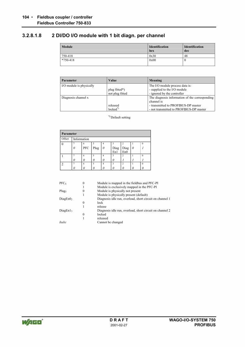
104 Fieldbus coupler / controllerFieldbus Controller 750-833
D R A F T WAGO-I/O-SYSTEM 7502001-02-27 PROFIBUS
3.2.8.1.8 2 DI/DO I/O module with 1 bit diagn. per channel
Module Identificationhex
Identificationdec
750-418 0x30 48*750-418 0x00 0
Parameter Value MeaningI/O module is physically The I/O module process data is:
plug fitted*) - supplied to the I/O modulenot plug fitted - ignored by the controller
Diagnosis channel x The diagnosis information of the correspondingchannel is
released - transmitted to PROFIBUS-DP masterlocked*) - not transmitted to PROFIBUS-DP master
*) Default setting
ParameterOffset Information0 7 6 5 4 3 2 1 0
0 PFC Plug 0 DiagEn1
DiagEn0
0 1
1 7 6 5 4 3 2 1 0
0 0 0 0 0 1 1 12 7 6 5 4 3 2 1 0
0 0 0 0 0 0 0 0
PFC6 01
Module is mapped in the fieldbus and PFC-PIModule is exclusively mapped in the PFC-PI
Plug5 01
Module is physically not presentModule is physically present (default)
DiagEn0201
Diagnosis idle run, overload, short circuit on channel 1lockrelease
DiagEn1301
Diagnosis idle run, overload, short circuit on channel 2lockedreleased
Italic Cannot be changed

Fieldbus coupler / controller 105Fieldbus Controller 750-833
WAGO-I/O-SYSTEM 750 D R A F TPROFIBUS 2001-02-27
3.2.8.1.9 Potential supply modules with diagnosis
Module Identificationhex
Identificationdec
750-610, 750-611 0x00 0
Parameter Value MeaningI/O module is physically The I/O module process data is:
plug fitted*) - supplied by the I/O modulenot plug fitted - set to zero by the controller
Diagnosis field voltage failureDiagnosis fuse blown
The diagnosis information for the correspond-ing case is
released - transmitted to PROFIBUS-DP masterlocked*) - not transmitted to PROFIBUS-DP master
*) Default setting
ParameterOffset Information0 7 6 5 4 3 2 1 0
0 0 Plug 0 DiagEn1
DiagEn0
0 0
1 7 6 5 4 3 2 1 0
0 0 0 0 0 0 0 02 7 6 5 4 3 2 1 0
0 0 0 0 0 0 0 0
Plug5 01
Module is physically not presentModule is physically present (default)
DiagEn02 01
Diagnosis field voltage failure info, lockDiagnosis field voltage failure info., release
DiagEn13 01
Diagnosis fuse failure info. lockDiagnosis fuse failure info. release
Italic Cannot be changed

106 Fieldbus coupler / controllerFieldbus Controller 750-833
D R A F T WAGO-I/O-SYSTEM 7502001-02-27 PROFIBUS
3.2.8.2 Analog I/O modules
All analog I/O modules have 2 byte extendable parameterisation information,which serves for the identification on the internal bus and the structure of themapping table.
With analog inputs 2 bytes follow which are reserved for future options. Mod-ules with diagnosis capability allow the diagnosis message to be suppressed orreleased channel for channel.
Analog outputs contain 4 byte parameterisation data. In this case the substitutevalues are saved for a maximum of 2 channels (2 words).
3.2.8.2.1 2 AI modules
Module Identificationhex
Identificationdec
750-461, 750-462, 750-469, 750-465, 750-466, 750-467,750-472, 750-474, 750-476, 750-478, 750-479, 750-480,750-491
0x51 81
Parameter Value MeaningI/O module is physically The I/O module process data is:
plug fitted*) - supplied by the I/O modulenot plug fitted - set to zero by the controller
Diagnosis channel x The diagnosis information of the correspondingchannel is
released - transmitted to PROFIBUS-DP masterlocked*) - not transmitted to PROFIBUS-DP master
*) Presetting
ParameterOffset Information0 7 6 5 4 3 2 1 0
0 PFC Plug 0 DiagEn1
DiagEn0
0 0
1 7 6 5 4 3 2 1 0
reserved2 15 14 13 12 11 10 9 8
reserved3 7 6 5 4 3 2 1 0
reserved
PFC6 01
Module is mapped in the fieldbus and PFC-PIModule is exclusively mapped in the PFC-PI
Plug5 01
Module is physically not presentModule is physically present (default)
DiagEn02 01
Lock diagnosis channel 1Diagnosis channel 1 released
DiagEn13 01
Diagnosis channel 2 lockedDiagnosis channel 2 released
Italic Cannot be changed

Fieldbus coupler / controller 107Fieldbus Controller 750-833
WAGO-I/O-SYSTEM 750 D R A F TPROFIBUS 2001-02-27
3.2.8.2.2 4 AI module
Module Identificationhex
Identificationdec
750-468 0x53 83
Parameter Value MeaningI/O module is physically The I/O module process data is:
plug fitted*) - supplied by the I/O modulenot plug fitted - set to zero by the controller
Diagnosis channel x The diagnosis information of the correspondingchannel is
released*) - transmitted to PROFIBUS-DP masterlocked - not transmitted to PROFIBUS-DP master
*) Default settings
ParameterOffset Information0 7 6 5 4 3 2 1 0
0 PFC Plug 0 DiagEn1
DiagEn0
0 0
1 7 6 5 4 3 2 1 0
reserved2 15 14 13 12 11 10 9 8
reserved3 7 6 5 4 3 2 1 0
reserved
PFC6 01
Module is mapped in the fieldbus and PFC-PIModule is exclusively mapped in the PFC-PI
Plug5 01
Module is physically not presentModule is physically present (default)
DiagEn02 01
Lock diagnosis channel 1Diagnosis channel 1 released
DiagEn13 01
Diagnosis channel 2 lockedDiagnosis channel 2 released
Italic Cannot be changed

108 Fieldbus coupler / controllerFieldbus Controller 750-833
D R A F T WAGO-I/O-SYSTEM 7502001-02-27 PROFIBUS
3.2.8.2.3 2 AO modules
All analog output modules have 6 bytes of extended parameterised informationand offer the possibility to switch to parameterisable substitute values in caseof a master failure.
Module Identificationhex
Identificationdec
750-550, 750-552, 750-554, 750-556 0x61 97
Parameter Value MeaningI/O module is physically The I/O module process data is:
Plug fitted*) - supplied by the I/O moduleNot plug fitted - ignored by the controller
Diagnosis channel x The diagnosis information of the correspondingchannel is
Released - transmitted to PROFIBUS-DP masterLocked*) - not transmitted to PROFIBUS-DP master
Substitute value channel x0x0000 or 0x80000 or -32767... 0x7FFF... 32767
If, in the case of a PROFIBUS-DP fault, theswitching of substitute values is enabled by thebus controller parameterisation, this data istransmitted to the periphery in the case of afault.
*) Default setting
ParameterOffset Information0 7 6 5 4 3 2 1 0
0 PFC Plug 0 0 0 0 01 7 6 5 4 3 2 1 0
reserved2 15 14 13 12 11 9 8 7
SubVal_Ch1_HB3 7 6 5 4 3 2 1 0
SubVal_Ch1_LB4 15 14 13 12 11 10 9 8
SubVal_Ch2_HB5 7 6 5 4 3 2 1 0
SubVal_Ch2_LB
PFC6 01
Module is mapped in the fieldbus and PFC-PIModule is exclusively mapped in the PFC-PI
Plug5 01
Module is physically not presentModule is physically present (default)
SubVal_Ch1 0x0000:0xFFFF
Substitute value channel 1
SubVal_Ch2 0x0000:0xFFFF
Substitute value channel 2
Italic Cannot be changed

Fieldbus coupler / controller 109Fieldbus Controller 750-833
WAGO-I/O-SYSTEM 750 D R A F TPROFIBUS 2001-02-27
3.2.8.3 Special digital modules
All special digital modules have 2 bytes of extended parameterisation infor-mation which serves for the identification on internal bus and the structure ofthe mapping table.
Input modules (counter) are followed by 2 bytes which are reserved for futureoptions.
For output modules (PWM outputs) are followed by 6 byte of parameterisationdata which serve for the saving of substitute values for a maximum of 2 chan-nels (2 words).
3.2.8.3.1 Counter modules
Module Identificationhex
Identificationdec
750-404, 750-638 0xF2 242
Parameter Value MeaningI/O module is physically The I/O module process data is:
plug fitted*) - supplied by the I/O modulenot plug fitted - set to zero by the controller
*) Default setting
ParameterOffset Information0 7 6 5 4 3 2 1 0
0 PFC Plug 0 0 0 0 01 7 6 5 4 3 2 1 0
reserved2 15 14 13 12 11 9 8 7
reserved3 7 6 5 4 3 2 1 0
reserved
PFC6 01
Module is mapped in the fieldbus and PFC-PIModule is exclusively mapped in the PFC-PI
Plug5 01
Module is physically not presentModule is physically present (default)
Italic Cannot be changed

110 Fieldbus coupler / controllerFieldbus Controller 750-833
D R A F T WAGO-I/O-SYSTEM 7502001-02-27 PROFIBUS
3.2.8.3.2 PWM module
Module Identificationhex
Identificationdec
750-511 0xF2 242
Parameter Wert MeaningI/O module is physically The I/O module process data is:
plug fitted*) - supplied by the I/O module or supplied to the I/O module
not plug fitted - set to zero by the controller or ignored by controller
Substitute value channel x0x0000 *)
... 0x7FFF
If, in the case of a PROFIBUS-DP fault, theswitching of substitute values is enabled by thebus controller parameterisation, this data istransmitted to the periphery in the case of afault.
*) Default setting
ParameterOffset Information0 7 6 5 4 3 2 1 0
0 PFC Plug 0 0 0 0 01 7 6 5 4 3 2 1 0
1 0 1 1 1 1 0 12 15 14 13 12 11 9 8 7
reserved3 7 6 5 4 3 2 1 0
0 0 0 0 0 0 0 04 15 14 13 12 11 9 8 7
SubVal_Ch1_HB5 7 6 5 4 3 2 1 0
SubVal_Ch1_LB6 15 14 13 12 11 10 9 8
SubVal_Ch2_HB7 7 6 5 4 3 2 1 0
SubVal_Ch2_LB
Plug5 01
Module is physically not presentModule is physically present (default)
SubVal_Ch1 0x0000:0xFFFF
Substitute value channel 1
SubVal_Ch2 0x0000:0xFFFF
Substitute value channel 2
Italic Cannot be changed

Fieldbus coupler / controller 111Fieldbus Controller 750-833
WAGO-I/O-SYSTEM 750 D R A F TPROFIBUS 2001-02-27
3.2.8.4 Distance and Angle Messurment Modules
All interface modules for path and angle measurement have 2 bytes of ex-tended parameterisation information which serves for the identification on in-ternal bus and the structure of the mapping table. 2 further bytes follow whichare reserved for future options.
3.2.8.4.1 SSI generator interface
Module Identificationhex
Identificationdec
750-630 (Alternative) 0x93 147750-630 (Standard) 0x95 149
Parameter value MeaningI/O module is physically The I/O module process data is:
plug fitted*) - supplied by the I/O module or supplied to the I/O module
not plug fitted - set to zero by the controller or ignored by the controller
Diagnosis channel x The diagnosis information of the correspondingchannel is
released - transmitted to PROFIBUS-DP masterlocked*) - not transmitted to PROFIBUS-DP master
*) Default setting
ParameterOffset Information0 7 6 5 4 3 2 1 0
0 PFC Plug 0 0 DiagEn0
0 0
1 7 6 5 4 3 2 1 0
1 1 0 0 0 0 0 02 15 14 13 12 11 9 8 7
reserved3 7 6 5 4 3 2 1 0
reserved
PFC6 01
Module is mapped in the fieldbus and PFC-PIModule is exclusively mapped in the PFC-PI
Plug5 01
Module is physically not presentModule is physically present (default)
DiagEn02 01
Diagnosis locked (default)Diagnosis release
Italic Cannot be changed

112 Fieldbus coupler / controllerFieldbus Controller 750-833
D R A F T WAGO-I/O-SYSTEM 7502001-02-27 PROFIBUS
3.2.8.4.2 Incremental encoder interface
Module Identificationhex
Identificationdec
750-631, 750-637 0xB5 181
Parameter Value MeaningI/O module is physically The I/O module process data is:
plug fitted*) - supplied by the I/O module or supplied to the I/O module
not plug fitted - set to zero by the controller or ignored by the controller
Diagnosis channel x The diagnosis information of the correspondingchannel is
released - transmitted to PROFIBUS-DP masterlocked*) - not transmitted to PROFIBUS-DP master
*) Default setting
ParameterOffset Information0 7 6 5 4 3 2 1 0
0 PFC Plug 0 0 DiagEn0
0 0
1 7 6 5 4 3 2 1 0
reserved2 15 14 13 12 11 10 9 8
reserved3 7 6 5 4 3 2 1 0
reserved
PFC6 01
Module is mapped in the fieldbus and PFC-PIModule is exclusively mapped in the PFC-PI
Plug5 01
Module is physically not presentModule is physically present (default)
DiagEn02 01
Diagnosis locked (default)Diagnosis release
Italic Cannot be changed

Fieldbus coupler / controller 113Fieldbus Controller 750-833
WAGO-I/O-SYSTEM 750 D R A F TPROFIBUS 2001-02-27
3.2.8.4.3 Digital impulse interface
Module Identificationhex
Identificationdec
750-635 0xB3 179
Parameter Value MeaningI/O module is physically The I/O module process data is:
plug fitted*) - supplied by the I/O module or supplied to the I/O module
not plug fitted - set to zero by the controller or ignored by the controller
Diagnosis channel x The diagnosis information of the correspondingchannel is
released - transmitted to PROFIBUS-DP masterlocked*) - not transmitted to PROFIBUS-DP master
*) Default setting
ParameterOffset Information0 7 6 5 4 3 2 1 0
0 PFC Plug 0 0 DiagEn0
0 0
1 7 6 5 4 3 2 1 0
1 1 0 0 0 1 0 12 15 14 13 12 11 10 9 8
reserved3 7 6 5 4 3 2 1 0
reserved
PFC6 01
Module is mapped in the fieldbus and PFC-PIModule is exclusively mapped in the PFC-PI
Plug5 01
Module is physically not presentModule is physically present (default)
DiagEn02 01
Diagnosis locked (default)Diagnosis release
Italic Cannot be changed

114 Fieldbus coupler / controllerFieldbus Controller 750-833
D R A F T WAGO-I/O-SYSTEM 7502001-02-27 PROFIBUS
3.2.8.5 Serial interfaces
All serial interface modules have 2 bytes of extended parameter informationwhich serves for the identification on the internal bus and the structure of themapping table. 2 further bytes follow which are reserved for future options.
Module Identificationhex
Identificationdec
750-650, 750-651, 750-653, 750-654 (3 Byte) 0xB3 179750-650, 750-651, 750-653, 750-654 (5 Byte) 0xB5 181
Parameter Value MeaningI/O module is physically The I/O module process data is:
plug fitted*) - supplied by the I/O module or supplied to the I/O module
not plug fitted - set to zero by the controller or ignored by the controller
Diagnosis channel x The diagnosis information of the correspondingchannel is
released - transmitted to PROFIBUS-DP masterlocked*) - not transmitted to PROFIBUS-DP master
*) Default setting
ParameterOffset Information0 7 6 5 4 3 2 1 0
0 PFC Plug 0 0 DiagEn0
0 0
1 7 6 5 4 3 2 1 0
reserved2 15 14 13 12 11 10 9 8
reserved3 7 6 5 4 3 2 1 0
reserved
PFC6 01
Module is mapped in the fieldbus and PFC-PIModule is exclusively mapped in the PFC-PI
Plug5 01
Module is physically not presentModule is physically present (default)
DiagEn0 01
Diagnosis locked (default)Diagnosis release
Italic Cannot be changed

Fieldbus coupler / controller 115Fieldbus Controller 750-833
WAGO-I/O-SYSTEM 750 D R A F TPROFIBUS 2001-02-27
3.2.9 Diagnosis
The slave diagnosis of the bus controller comprises of a 6 byte standard diag-nosis, 9 byte identification based diagnosis, 7 byte device status and up to 42byte channel based diagnosis.
In the reply telegram of the diagnosis selection, in addition to the standard di-agnosis at least the identification based diagnosis and the device status aretransmitted. This could be followed by up to 14 channel based diagnosis mes-sages (3 byte per message).
Byte
0
1 Station status 1 to 3
2
3 PROFIBUS-DP master address
4 Manufacturer Identification
5
6
7 Identification based diagnosis
: :
14 :
15
Device status
21
22
Channel based diagnosis
(3 bytes per channel)
63

116 Fieldbus coupler / controllerFieldbus Controller 750-833
D R A F T WAGO-I/O-SYSTEM 7502001-02-27 PROFIBUS
3.2.9.1 Stations status 1 to 3
see EN 50170
3.2.9.2 PROFIBUS-DP master address
The PROFIBUS-DP master address is located in byte 3 of the slave diagnosisand contains the master address parameterised by the station and to which ithas write and read access.
3.2.9.3 Manufacturer identification
The manufacturer identification is located in byte 4 and 5 and contains a 16 bitcode, intended for the identification of the device or the device class.
3.2.9.4 Identification based diagnosis
The identification based diagnosis comprises of a bit field containing a bit in-formation for each connected module. The individual bit provides informationabout the current operating status. A 0 means no fault, a 1 indicates a faultymodule status. The bus controller can be fitted with up to 63 modules, so thatthe identification based diagnosis including header covers 9 bytes from byte 6to byte 14.
Byte Information Meaning
6 0 1 0 0 1 0 0 1 Header byte(9 byte identification based diagnosisincl. header)
7 7 6 5 4 3 2 1 0
8 15 14 13 12 11 10 9 8
9 23 22 21 20 19 18 17 16 Diagnosis allocation to
10 31 30 29 28 27 26 25 24 I/O module n (n=1 ... 63)
11 39 38 37 36 35 34 33 32 Controller (n=0)
12 47 46 45 44 43 42 41 40
13 55 54 53 52 51 50 49 48
14 63 62 61 60 59 58 57 56

Fieldbus coupler / controller 117Fieldbus Controller 750-833
WAGO-I/O-SYSTEM 750 D R A F TPROFIBUS 2001-02-27
3.2.9.5 Device status
The device status includes the required overhead 7 Byte and transmits internalstatus information as well as information relating to the internal bus,PROFIBUS-DP and the PFC running time system to the master or the higherranking controls.
Byte Information Meaning
15 0 0 0 0 0 1 1 1 Header byte(7 Byte status informationincl. header)
16 1 0 1 0 0 0 0 0 Status type(manufacturer specific device status)
17 0 0 0 0 0 0 0 0 Slot number 0
18 0 0 0 0 0 0 0 0 Status differentiation(none)
19 q q n n n n n n Status messageq Status source
'00' Internal status'01' Internal bus status'10' PROFIBUS DP status'11' PFC-RTS status
n Status number
20 x x x x x x x x Status argument
21 0 0 0 0 0 0 0 0 Reserved

118 Fieldbus coupler / controllerFieldbus Controller 750-833
D R A F T WAGO-I/O-SYSTEM 7502001-02-27 PROFIBUS
3.2.9.5.1 Internal status messages and arguments
Statusmessage
Statusargument
Description
0x00 0x00 no fault
0x01 0x00 EEPROM check sum fault / check sum fault in the flash pa-rameter area
0x01 0x01 Overflow inline code buffer
0x01 0x02 Unknown data type
0x01 0x03 Module type for flash program memory could not be deter-mined / is incorrect
0x01 0x04 Fault when writing in the FLASH memory
0x01 0x05 Fault when deleting the FLASH memory
0x01 0x06 Changed I/O modules configuration determined afterAUTORESET
0x01 0x07 Fault when writing in the serial EEPROM
0x01 0x08 Invalid firmware
0x02 0x00 Incorrect table entry
0x07 n Module at position n (n = 1...63) is not supported
3.2.9.5.2 Internal bus status messages and arguments
Statusmessage
Statusargument
Description
0x63 0xFF At least one module cannot interpret an internal bus command
0x64 0x00 A data fault or a internal bus interruption exists behind thebus controller
0x64 n An internal bus interruption exists behind module n
0x65 n Fault during register communication with module n

Fieldbus coupler / controller 119Fieldbus Controller 750-833
WAGO-I/O-SYSTEM 750 D R A F TPROFIBUS 2001-02-27
3.2.9.5.3 PROFIBUS-DP status messages and arguments
Statusmessage
Statusargument
Description
0x81 0x01 Insufficient parameter data configuration data
0x81 0x02 Excessive parameterisation data
0x82 n Faulty n. parameterisation byte
0x83 0x01 Insufficient configuration data
0x83 0x02 Excessive configuration data
0x84 n Faulty n. configuration byte (module)
0x85 0x01 Maximum input data length exceeded
0x85 0x02 Maximum output data length exceeded
0x86 0x01 Compilate buffer overflow for DP process image
0x86 0x02 Compilate buffer overflow for PFC process image
3.2.9.5.4 PFC-RTS status messages and arguments
Statusmessage
Statusargument
Description
0xC1 0x00 t. b. d.
0xC1 0x01 t. b. d.
0xC2 0x00 t. b. d.

120 Fieldbus coupler / controllerFieldbus Controller 750-833
D R A F T WAGO-I/O-SYSTEM 7502001-02-27 PROFIBUS
3.2.9.6 Channel based diagnosis
The channel based diagnosis serves for detailing the identification based diag-nosis. A structure is added to the device status for each faulty slot. This com-prises of a header byte, a byte, the channel type and the channel number and athird which describes the fault type and the channel organisation.
Byte Information Meaning
22 1 0 x x x x x x Header channel based diagnosis(x: 1 to 63, slots of the module)
23 a a x x x x x x Channel type (a) andchannel number x: 0 to 3
0 1 Input channel
1 0 Output channel
1 1 Input / output channel
24 t t t x x x x x Channel type (t) andfault type (x)
0 0 0 No allocation
0 0 1 1 bit
0 1 0 2 bit
0 1 1 4 bit
1 0 0 1 byte
1 0 1 1 word
1 1 0 2 words
25-27 Next channel based diagnosis message (as byte 22 24)
28-30 Next channel based diagnosis message (as byte 22 24)
... ...
61-63 Last representable channel based diagnosis message (as byte 22 24)
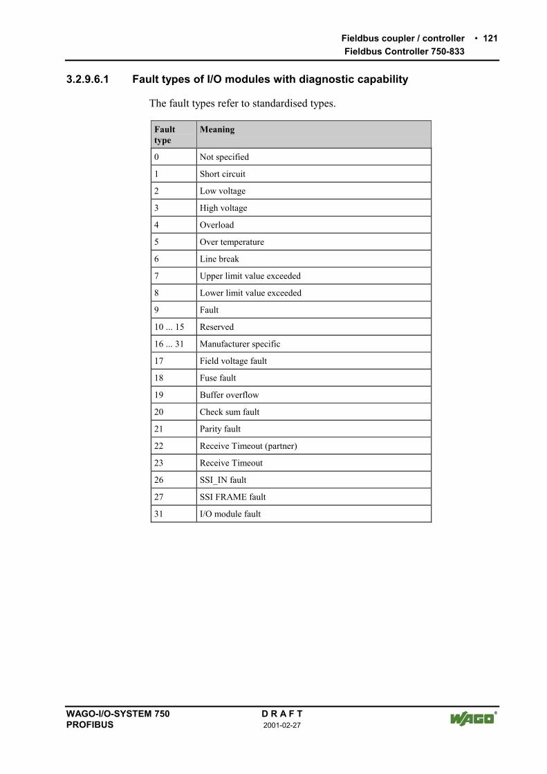
Fieldbus coupler / controller 121Fieldbus Controller 750-833
WAGO-I/O-SYSTEM 750 D R A F TPROFIBUS 2001-02-27
3.2.9.6.1 Fault types of I/O modules with diagnostic capability
The fault types refer to standardised types.
Faulttype
Meaning
0 Not specified
1 Short circuit
2 Low voltage
3 High voltage
4 Overload
5 Over temperature
6 Line break
7 Upper limit value exceeded
8 Lower limit value exceeded
9 Fault
10 ... 15 Reserved
16 ... 31 Manufacturer specific
17 Field voltage fault
18 Fuse fault
19 Buffer overflow
20 Check sum fault
21 Parity fault
22 Receive Timeout (partner)
23 Receive Timeout
26 SSI_IN fault
27 SSI FRAME fault
31 I/O module fault

122 Fieldbus coupler / controllerFieldbus Controller 750-833
D R A F T WAGO-I/O-SYSTEM 7502001-02-27 PROFIBUS
3.2.9.6.2 I/O modules fault cases
Article number Channeltype Fault type Meaning
750-418, 750-419,750-507, 750-522
'001 0.1001' Fault (line break, overload or shortcircuit)
750-506 '001 0.0001'0.0010'0.0110'0.1001'
Short circuitLower voltageLine breakError
750-461, 750-469 '101 0.0110'0.1000'1.0000'1.1111'
Line breakLower limit value gone belowParameterisation faultI/O module fault
750-462, 750-465,750-466, 750-472,750-474, 750-479,750-480
'101 0.0111'0.1000'1.0000'1.1111'
Lower limit value gone belowUpper limit value exceededParameterisation faultI/O module fault
750-610, 750-611, '001 1.0001'1.0010'
Field voltage faultFuse fault
750-630 '110 1.1010'1.1011'1.0000'1.1111'
SSI_IN fault (external fault)SSI FRAME faultParameterisation faultI/O module fault
750-635, 750-637 '110 0.1001'1.0000'1.1111'
ErrorParameterisation faultI/O module fault
750-650, 750-651,750-653, 750-654
'110('000)
0.1001'1.0000'1.1111'
Buffer overflowParameterisation faultI/O module fault

Fieldbus coupler / controller 123Fieldbus Controller 750-833
WAGO-I/O-SYSTEM 750 D R A F TPROFIBUS 2001-02-27
3.2.10 Commissioning (start-up) with WAGO-I/O-PRO
in preparation

124 Fieldbus coupler / controllerFieldbus Controller 750-833
D R A F T WAGO-I/O-SYSTEM 7502001-02-27 PROFIBUS
3.2.11 LED signalling
For the on-site diagnosis the controller has several LED´s, which display theoperating status of the controller or the complete node.
24V 0V
+ +
RUN
BF
DIA
BUS
I/O
USR
PROFIBUS
C
DB
A
Fig. 3-22: Display element 750-833 g012107x
3.2.11.1 Blink code
A blink code displays detailed fault messages. A fault is cyclically displayedusing up to 3 different blink sequences.
• The first blink sequence (approx. 10 Hz) indicates the fault display.
• After a pause a second blink sequence appears (approx. 1 Hz). The numberof blink impulses gives the fault code.
• The third blink sequence (approx. 1 Hz) appears following a further pause.The number of blink pulses indicates the fault argument.

Fieldbus coupler / controller 125Fieldbus Controller 750-833
WAGO-I/O-SYSTEM 750 D R A F TPROFIBUS 2001-02-27
3.2.11.2 Fieldbus status
The upper four LED´s signal the operating status of the PROFIBUS communi-cation.
LED Colour Meaning
RUN green The 'RUN' LED shows the user whether the fieldbus controller isfunctioning correctly.
BF red The 'BF' LED indicates whether the communication is functioningvia the PROFIBUS.
DIA red The 'DIA' LED indicates an external diagnosis.
BUS red The 'BUS' LED signals a projecting fault.
RUN BF DIA BUS Meaning
off off off off The controller is not supplied with operating volt-age (Status LED of the bus controller does not lightup) or a hardware fault exists.
on on * off PROFIBUS interface started, baud rate not yetrecognised.
on blinks * off Baud rate recognised, station is not yet parameter-ised and configured.
on blinks on blinkscycli-cally
Slave was incorrectly projected.Fault message via a blink code
on off * off The controller is exchanging data.
on * on * The controller signals a pending diagnosis.
* Not relevant

126 Fieldbus coupler / controllerFieldbus Controller 750-833
D R A F T WAGO-I/O-SYSTEM 7502001-02-27 PROFIBUS
3.2.11.3 Fault message by means of blink code of the BUS-LED
Fault argument Fault description
Fault code 1: Fault in parameterisation telegram
1 insufficient parameterisation data
2 excessive parameterisation data
Fault code 2: Fault in parameterisation telegram
n Parameterisation byte n is faulty
Fault code 3: Fault in configuration telegram
1 insufficient configuration data
2 excessive configuration data
Fault code 4: Fault in configuration telegram
n Configuration byte (module) n is faulty
Fault code 5: Faulty data length
1 maximum input data length exceeded
2 maximum output data length exceeded
Fault code 6: Compilate buffer overflow
1 Compilate buffer overflow for DP process image
2 Compilate buffer overflow for PFC process image

Fieldbus coupler / controller 127Fieldbus Controller 750-833
WAGO-I/O-SYSTEM 750 D R A F TPROFIBUS 2001-02-27
3.2.11.4 Node status
The 'I/O' LED indicates the node operation and signals the occurrence of afault.
I/O USR Meaning
green * Data cycle on the internal bus
off * No data cycle on the internal bus
red on Bus controller is in bootstrap mode or hardware defect on the controllersystems
redblinks
* During start up: internal bus being initialisedDuring operation: general internal bus fault
redblinks
* Fault message during internal bus reset and internal fault
orange * FLASH access to bus device firmware
* Not relevant
The controller starts up after switching on the supply voltage. The "I/O" LEDblinks. The "I/O" LED has a steady light following a fault free run-up.In the case of a fault the "I/O" LED continues blinking. The fault is cyclicallydisplayed by the blink code.
“I/O”-LED an
Versorgungsspannungeinschalten
Koppler-Hochlauf
“I/O”-LED blinkt
Feldbusstart
JaFehler
Nein
“I/O”-LED1. Blinksequenz(leitet opt. Anzeige eines Fehlers ein)
1. Pause
“I/O”-LED2. BlinksequenzFehlercode (Anzahl Blinkimpulse)
2. Pause
“I/O”-LED3. BlinksequenzFehlerargument (Anz. Blinkimp.)
Fig. 3-23: Signalling the LED node status g012111d
After overcoming a fault restart the controller by switching off the supply volt-age and then on again.

128 Fieldbus coupler / controllerFieldbus Controller 750-833
D R A F T WAGO-I/O-SYSTEM 7502001-02-27 PROFIBUS
3.2.11.5 Fault message via blink code from the I/O-LED
Fault argument Fault description
Fault code 1: Hardware and configuration fault
0 EEPROM check sum fault / check sum fault in the parameter area ofthe flash memory
1 Overflow of the internal buffer memory for the inline code
2 Unknown data type
3 Module type of the flash program memory could not be determined /is incorrect
4 Fault when writing in the FLASH memory
5 Fault when deleting the FLASH memory
6 Changed I/O module configuration determined after AUTORESET
7 Fault when writing in the serial EEPROM
8 Invalid firmware
Fault code 2: Fault in programmed configuration
0 Incorrect table entry
Fault code 3: Internal bus command fault
0 Internal bus(es) has (have) identified internal bus commands as in-correct
Fault code 4: Internal bus data fault
0 Data fault on internal bus orInternal bus interruption on controller
n* (n>0) Internal bus interrupted after I/O module n
Fault code 5: Fault during register communication
n* Internal bus fault during register communication with I/O module n
Fault code 7: I/O module is not supported
n* I/O module at position n is not supported
* The number of blink pulses (n) indicates the position of the I/O module. I/O moduleswithout data are not counted (e.g. supply modules without diagnosis)
Example: The 13th I/O module has been removed.
1. The "I/O" LED starts the fault display with the first blink sequence (approx. 10 Hz).
2. The second blink phase (approx. 1 Hz) follows the first pause. The "I/O" LED blinksfour times and thus signals the fault code 4 (internal bus data fault).
3. The third blink sequence follows the second pause. The "I/O ERR" LED blinks twelvetimes. The fault argument 12 means that the internal bus is interrupted after the 12th
I/O module.
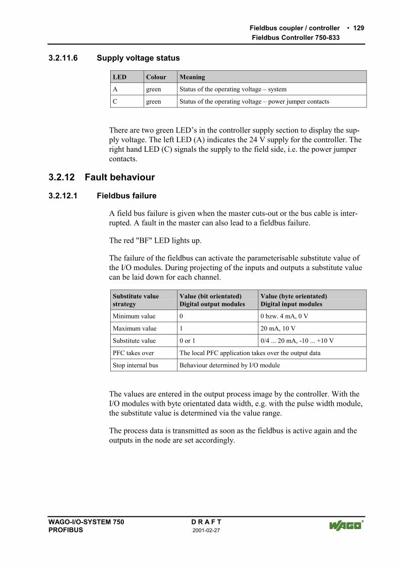
Fieldbus coupler / controller 129Fieldbus Controller 750-833
WAGO-I/O-SYSTEM 750 D R A F TPROFIBUS 2001-02-27
3.2.11.6 Supply voltage status
LED Colour Meaning
A green Status of the operating voltage system
C green Status of the operating voltage power jumper contacts
There are two green LEDs in the controller supply section to display the sup-ply voltage. The left LED (A) indicates the 24 V supply for the controller. Theright hand LED (C) signals the supply to the field side, i.e. the power jumpercontacts.
3.2.12 Fault behaviour
3.2.12.1 Fieldbus failure
A field bus failure is given when the master cuts-out or the bus cable is inter-rupted. A fault in the master can also lead to a fieldbus failure.
The red "BF" LED lights up.
The failure of the fieldbus can activate the parameterisable substitute value ofthe I/O modules. During projecting of the inputs and outputs a substitute valuecan be laid down for each channel.
Substitute valuestrategy
Value (bit orientated)Digital output modules
Value (byte orientated)Digital input modules
Minimum value 0 0 bzw. 4 mA, 0 V
Maximum value 1 20 mA, 10 V
Substitute value 0 or 1 0/4 ... 20 mA, -10 ... +10 V
PFC takes over The local PFC application takes over the output data
Stop internal bus Behaviour determined by I/O module
The values are entered in the output process image by the controller. With theI/O modules with byte orientated data width, e.g. with the pulse width module,the substitute value is determined via the value range.
The process data is transmitted as soon as the fieldbus is active again and theoutputs in the node are set accordingly.

130 Fieldbus coupler / controllerFieldbus Controller 750-833
D R A F T WAGO-I/O-SYSTEM 7502001-02-27 PROFIBUS
3.2.12.2 Internal bus fault
An internal bus fault is created, for example, if an I/O module is removed. Ifthis fault occurs during operation the output modules behave in the same man-ner as an I/O module stop. The input process image is set in accordance withthe projected strategy.
The "I/O" LED blinks red. The slave generates a detailed diagnosis message.
Once the internal bus fault has been overcome the controller starts up againautomatically in accordance with the parameterised restart behaviour. Thetransfer of the process data is then resumed and the node outputs are corre-spondingly set.

Fieldbus coupler / controller 131Fieldbus Controller 750-833
WAGO-I/O-SYSTEM 750 D R A F TPROFIBUS 2001-02-27
3.2.13 Technical data
System data
Number of I/O modules 96 with repeater
Number of I/O points approx. 6000 (master dependent)
Transfer medium Cu cable as per EN 50170
Bus segment length 100 m ... 1200 m(baud rate dependent / cable dependent)
Transmission rate 9.6 kbaud ... 12 Mbaud
Transmission time for 10 moduleseach with 32 DI and 32 DO
type 1 msmax. 3.3 ms
Bus connection 1 x D-SUB 9; socket
ProgrammingIEC 61131-3
WAGO-I/-PROIL, LD, FBD, ST, FSC
Standards and approvals
UL (UL508) E175199
Standard EN 50 170
Conformity symbol CE
Technical data
Number of I/O modules 63
Protocol DP / DPV1
Input process image max. 128 byte
Output process image max. 128 byte
Configuration via PC or controls
Voltage supply DC 24 V (-15 % / + 20 %)
Input currentmax 500 mA at 24 V
Internal system supply module effi-ciency
87 %
Internal current consumption 200 mA at 5 V
Total current for I/O modules 1800 mA at 5 V
Voltage via power jumper contacts DC 24 V (-15 % / + 20 %)
Current via power jumper contactmax DC 10 A
Dimensions (mm) W x H x D 51 x 65* x 100 (*from mounting rail top edge)
Weight ca. 195 g
EMC interference resistance as per EN 50082-2 (95)
EMC interference transmission as per EN 50081-2 (94)

132 I/O ModulesList of Digital Input Modules
D R A F T WAGO-I/O-SYSTEM 7502001-02-27 PROFIBUS
4 I/O Modules4.1 Digital Input Modules
4.1.1 List of Digital Input Modules
4.1.2 750-414 [4 DI 5 V 0,2ms]
4.2 Digital Output Modules
4.2.1 List of Digital Output Modules
4.3 Analog Input Modules
4.3.1 List of Analog Input Modules
4.4 Analog Output Modules
4.4.1 List of Analog Output Modules
4.5 ...
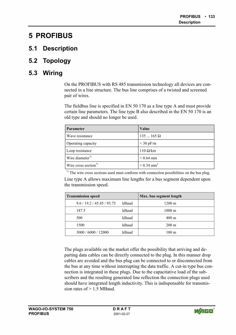
PROFIBUS 133Description
WAGO-I/O-SYSTEM 750 D R A F TPROFIBUS 2001-02-27
5 PROFIBUS5.1 Description
5.2 Topology
5.3 WiringOn the PROFIBUS with RS 485 transmission technology all devices are con-nected in a line structure. The bus line comprises of a twisted and screenedpair of wires.
The fieldbus line is specified in EN 50 170 as a line type A and must providecertain line parameters. The line type B also described in the EN 50 170 is anold type and should no longer be used.
Parameter Value
Wave resistance 135 ... 165 Ω
Operating capacity < 30 pF/m
Loop resistance 110 Ω/km
Wire diameter*) > 0.64 mm
Wire cross section*) > 0.34 mm2
*) The wire cross sections used must conform with connection possibilities on the bus plug.
Line type A allows maximum line lengths for a bus segment dependent uponthe transmission speed.
Transmission speed Max. bus segment length
9.6 / 19.2 / 45.45 / 93.75 kBaud 1200 m
187.5 kBaud 1000 m
500 kBaud 400 m
1500 kBaud 200 m
3000 / 6000 / 12000 kBaud 100 m
The plugs available on the market offer the possibility that arriving and de-parting data cables can be directly connected to the plug. In this manner dropcables are avoided and the bus plug can be connected to or disconnected fromthe bus at any time without interrupting the data traffic. A cut-in type bus con-nection is integrated in these plugs. Due to the capacitative load of the sub-scribers and the resulting generated line reflection the connection plugs usedshould have integrated length inductivity. This is indispensable for transmis-sion rates of > 1.5 MBaud.

134 PROFIBUSWiring
D R A F T WAGO-I/O-SYSTEM 7502001-02-27 PROFIBUS
6 6
3 3
1 1
9 9
8
7
2 2
4 4
7
8
5 5
VP
390
3
90
220
RxD/TxD-PRxD/TxD-P
RxD/TxD-NRxD/TxD-N
DGND
9-pol. D-SUBSteckermit Busabschluss
9-pol. D-SUBStecker
WeitereFeldbusteilnehmer
Pin 3 - B-Leitung
Pin 8 - A-Leitung
Längsinduktivität = 110 nH
Fig. 5-1: Bus connection g012102d
NoteWhen connecting the subscriber ensure that the data lines are not mixed up.The bus termination at the start and end of the bus line must be installed. Thebus connection requires the supply voltage VP from the device. For this rea-son ensure that the slave unit installed on the bus termination, is always sup-plied with voltage.Due to the integrated length inductivity in the connection plug ensure that theplug is installed without connected field devices as the missing capacity ofthe device could cause transmission faults.
In order to achieve a high disturbance resistance of the system against electro-magnetic radiated interference ensure that a screened PROFIBUS cable isused. Where possible connect the screen at both ends with good conductionand using large surface area screen clips. In addition ensure that the cables arelaid separated from all power line cables if possible. With a data rate of ≥1.5Mbit/s ensure that spur lines are avoided.
iFurther informationThe PNO provides further documentation for its members in INTERNET. Ca-ble specification information can be obtained from, for example, the Installa-tion Guideline for PROFIBUS-FMS/DP", 2.112
http://www.profibus.com/
NoteWAGO offers this screen connection system for the optimum connectionbetween fieldbus screening and function earth.

Configuration example 135NETCON
WAGO-I/O-SYSTEM 750 D R A F TPROFIBUS 2001-02-27
6 Configuration example6.1 NETCON
in preparation
6.2 Step 7in preparation
6.3 COM Profibusin preparation

136 Explosive EnvironmentsForeword
D R A F T WAGO-I/O-SYSTEM 7502001-02-27 PROFIBUS
7 Explosive Environments7.1 Foreword
Todays development shows that many chemical and petrochemical companieshave production plants and process automation machines in operation whichuse gas-air, vapor-air and dust-air mixtures which can be explosive. For thisreason, the electrical components used in such plants and systems must notpose a risk of explosion resulting in injury to persons or damage to property.This is backed by law, directives or regulations, on a national and internationalscale. WAGO-I/O-SYSTEM 750 is designed for use in zone 2 explosive envi-ronments, for which reason the following basic explosion protection relatedterms have been defined.
7.2 Protective measuresPrimarily, explosion protection describes how to prevent the formation of anexplosive atmosphere. For instance by avoiding the use of combustible liq-uids, reducing the concentration levels, ventilation measures, to name but afew. But there are a large number of applications, which do not allow the im-plementation of primary protection measures. In such cases, the secondary ex-plosion protection comes into play. Following is a detailed description of suchsecondary measures.
7.3 Classification meeting CENELEC / IECThe specifications outlined here are valid for use in Europe and are based onthe following standards: EN50... of CENELEC (European Committee forElectrotechnical Standardisation) and IEC79-... of IEC (International Electro-technical Commission):
7.3.1 Division into zones
Explosive environments are areas arein which the atmosphere can potentiallybecome explosive. The term explosive means a special mixture of ignitablesubstances existing in the form of air-borne gases, fumes, mist or dust underatmospheric conditions which, when heated beyond a tolerable temperature orsubjected to an electric arc or sparks, can produce explosions. Explosive zoneshave been created to describe the concentrations level of an explosive atmos-phere. This division is based on the probability of an explosion occurring.

Explosive Environments 137Classification meeting CENELEC / IEC
WAGO-I/O-SYSTEM 750 D R A F TPROFIBUS 2001-02-27
Explosive areas resulting from combustible gases, fumes or mist:
• Zone 0 areas are subject to an explosive atmosphere(> 1000 h /year) continuously or for extended periods.
• Zone 1 areas can expect the occasional occurrence of an explosive atmos-phere (> 10 h ≤ 1000 h /year).
• Zone 2 areas can expect the rare or short-term occurrence of an explosiveatmosphere (> 0 h ≤ 10 h /year).
Explosive areas subject to air-borne dust:
• Zone 20 areas are subject to an explosive atmosphere(> 1000 h /year) continuously or for extended periods.
• Zone 21 areas can expect the occasional occurrence of an explosive atmos-phere (> 10 h ≤ 1000 h /year).
• Zone 22 areas can expect the rare or short-term occurrence of an explosiveatmosphere (> 0 h ≤ 10 h /year).
7.3.2 Explosion protection group
In addition, the electrical components for explosive areas are subdivided intotwo groups:
Group I: Group I includes electrical components for use in fire-dampmine structures.
Group II: Group II includes electrical components for use in all otherexplosive environments. The group is further subdivided bypertinent combustible gasesin the environment.Subdivision IIA, IIB and IIC takes into account that differ-ent materials/substances/gases have various ignition energycharacteristic values. For this reason the three sub-groupsare assigned representative types of gases:
• IIA Propane• IIB Ethylene• IIC Hydrogen
Minimal ignition energy of representative types of gases
Explosion group I IIA IIB IIC
Gases Methane Propane Ethylene Hydrogen
Ignition energy (mWs) 0,28 0,25 0,082 0,016

138 Explosive EnvironmentsClassification meeting CENELEC / IEC
D R A F T WAGO-I/O-SYSTEM 7502001-02-27 PROFIBUS
7.3.3 Unit categories
Moreover, the areas of use (zones) and the conditions of use (explosiongroups) are subdivided into categories for the electrical operating means:
Unitcategories
Explosiongroup
Area of use
M1 I Fire-damp protection
M2 I Fire-damp protection
1G II Zone 0 Explosivi environment by gas, fumes or mist
2G II Zone 1 Explosive environment by gas, fumes or mist
3G II Zone 2 Explosive environment by gas, fumes or mist
1D II Zone 20 Explosive environment by dust
2D II Zone 21 Explosive environment by dust
3D II Zone 22 Explosive environment by dust

Explosive Environments 139Classification meeting CENELEC / IEC
WAGO-I/O-SYSTEM 750 D R A F TPROFIBUS 2001-02-27
7.3.4 Temperature classes
The maximum surface temperature for electrical components of explosionprotection group I is 150 °C (danger due to coal dust deposits) or 450 °C (ifthere is no danger of coal dust deposit).
In line with the maximum surface temperature for all ignition protection types,the electrical components are subdivided into temperature classes, as far aselectrical components of explosion protection group II are concerned. Here thetemperatures refer to a surrounding temperature of 40 °C for operation andtesting of the electrical components. The lowest ignition temperature of theexisting explosive atmosphere must be higher than the maximum surface tem-perature.
Temperature classes Maximum surfacetemperature
Ignition temperatureof the combustible materials
T1 450 °C > 450 °C
T2 300 °C > 300 °C ≤ 450 °C
T3 200 °C > 200 °C ≤ 300 °C
T4 135 °C > 135 °C ≤ 200 °C
T5 100 °C >100 °C ≤ 135 °C
T6 85°C > 85 °C ≤ 100 °C
The following table represents the division and attribution of the materials tothe temperature classes and material groups in percent:
Temperature classesT1 T2 T3 T4 T5 T6 Total
28 % 37,6 % 30.5 %96,5 %
3,1 % 0 % 0,3 % 351
Explosion groupIIA IIB IIC Total80,2 % 18,1 % 0,7 % 436
7.3.5 Types of ignition protection
Ignition protection defines the special measures to be taken for electrical com-ponents in order to prevent the ignition of surrounding explosive atmospheres.For this reason a differentiation is made between the following types of igni-tion protection:

140 Explosive EnvironmentsClassification meeting CENELEC / IEC
D R A F T WAGO-I/O-SYSTEM 7502001-02-27 PROFIBUS
Identification CENELEC stan-dard
Explanation Application
EEx o EN 50 015 Oil encapsulation Zone 1 + 2
EEx p EN 50 016 Overpressure encapsulation Zone 1 + 2
EEx q EN 50 017 Sand encapsulation Zone 1 + 2
EEx d EN 50 018 Pressure resistant encapsu-lation
Zone 1 + 2
EEx e EN 50 019 Increased safety Zone 1 + 2
EEx m EN 50 028 Cast encapsulation Zone 1 + 2
EEx i EN 50 020 (Unit)EN 50 039 (System)
Intrinsic safety Zone 0 + 1 + 2
EEx n EN 50 021 Components for zone 2(see below)
Zone 2
Ignition protection n describes exclusively the use of explosion protectedcomponents in zone 2. This zone encompasses three areas where explosiveatmospheres can only be expected to occur rarely or short-term. It representsthe transition between the area of zone 1, which requires an explosion protec-tion and safe area in which for instance welding is allowed at any time.
Regulations covering these electrical components are being prepared on aworld-wide scale. The standard EN 50 021 allows electrical component manu-facturers to obtain certificates from the corresponding authorities for instanceKEMA in the Netherlands or the PTB in Germany, certifying that the testedcomponents meet the above mentioned standards draft.
Type n ignition protection additionally requires electrical components to bemarked , with the following extended identification:
• A non spark generating (function modules without relay /withoutswitches), previously V
• AC spark generating, contacts protected by seals (function modules withrelays / without switches), previously VW
• L limited energy (function modules with switch)
iMore informationFor more detailed information please refer to the national and/or interna-tional standards, directives and regulations!

Explosive Environments 141Classifications meeting the NEC
WAGO-I/O-SYSTEM 750 D R A F TPROFIBUS 2001-02-27
7.4 Classifications meeting the NECThe following classifications according to NEC 500 (National Electric Code)are valid for North America, in contrast to the specifications governing use inEurope:
7.4.1 Division into zones
An indication for the probability of a danger of whatever type it may be issubdivided into Divisions. Here are the following descriptions:
Explosion endangered areas due to combustible gases, fumes, mist and dust:
Division 1 encompasses areas in which explosive atmospheres are to be expectedoccasionally (> 10 h ≤ 1000 h /year) as well as continuously and long-term (> 1000 h /year).
Division 2 encompasses areas in which explosive atmospheres can be expected rarelyand short-term (>0 h ≤ 10 h /year).
7.4.2 Explosion protection groups
Electrical components for explosion endangered areas are subdivided in threedanger categories:
Class I (gases and fumes): Group A (Acetylene)Group B (Hydrogen)Group C (Ethylene)Group D (Methane)
Class II (dust): Group E (Metal dust)Group F (Coal dust)Group G (Flour, starch and cereal dust)
Class III (fibers): No sub-groups
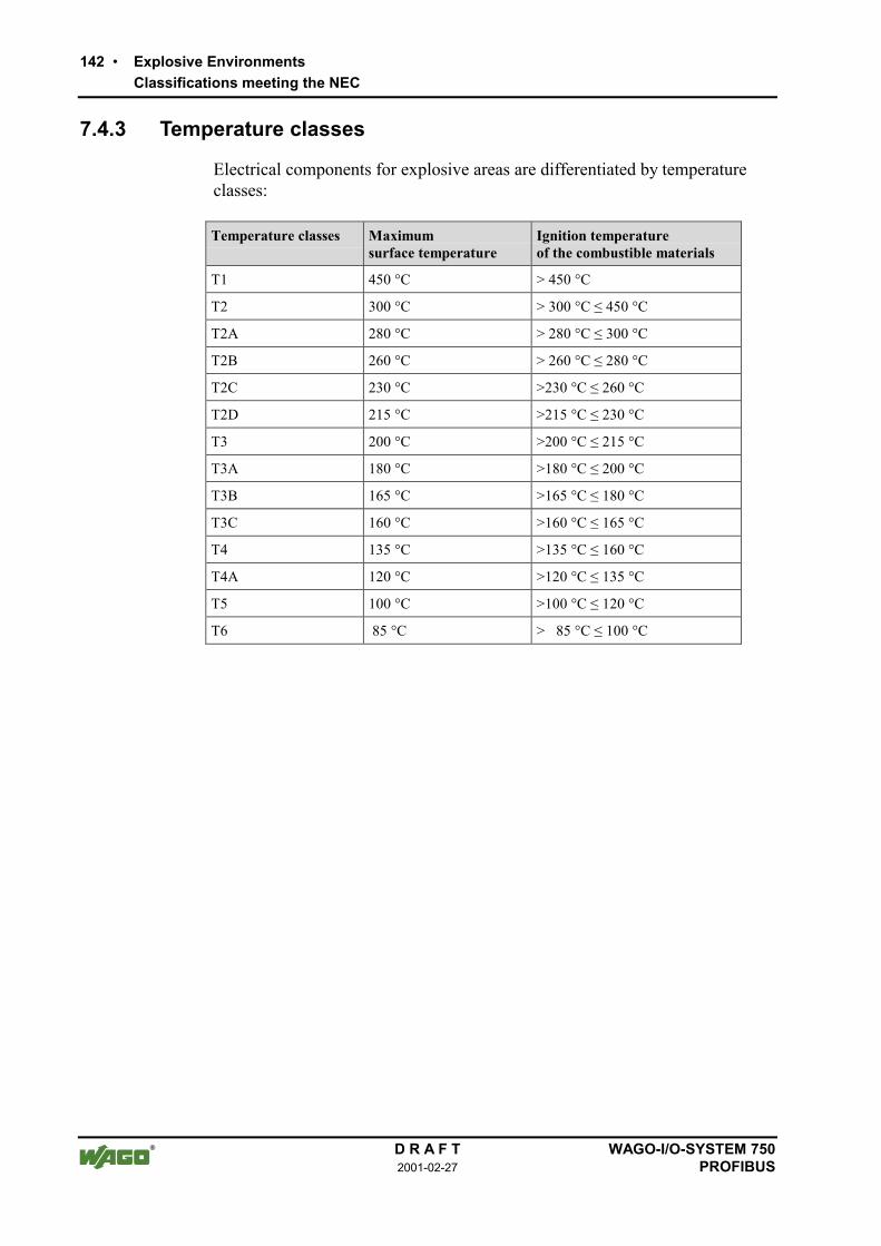
142 Explosive EnvironmentsClassifications meeting the NEC
D R A F T WAGO-I/O-SYSTEM 7502001-02-27 PROFIBUS
7.4.3 Temperature classes
Electrical components for explosive areas are differentiated by temperatureclasses:
Temperature classes Maximumsurface temperature
Ignition temperatureof the combustible materials
T1 450 °C > 450 °C
T2 300 °C > 300 °C ≤ 450 °C
T2A 280 °C > 280 °C ≤ 300 °C
T2B 260 °C > 260 °C ≤ 280 °C
T2C 230 °C >230 °C ≤ 260 °C
T2D 215 °C >215 °C ≤ 230 °C
T3 200 °C >200 °C ≤ 215 °C
T3A 180 °C >180 °C ≤ 200 °C
T3B 165 °C >165 °C ≤ 180 °C
T3C 160 °C >160 °C ≤ 165 °C
T4 135 °C >135 °C ≤ 160 °C
T4A 120 °C >120 °C ≤ 135 °C
T5 100 °C >100 °C ≤ 120 °C
T6 85 °C > 85 °C ≤ 100 °C

Explosive Environments 143Identification acc. to CENELEC, IEC and ATEX 100a
WAGO-I/O-SYSTEM 750 D R A F TPROFIBUS 2001-02-27
7.5 Identification acc. to CENELEC, IEC and ATEX 100a
Hansastr. 27D-32423 Minden
ITEM-NO.:750-400
2DI 24V DC 3.0ms
0.08-2.5mm2
0V 24V DI1
Di2
PATENTS PENDINGII 3 GKEMA 01ATEX1024 XEEx nA II T4
CL
ID
IVG
rp.
AB
CD
opte
mp
code
T4A
24V
DC
AW
G28
-14
55°C
max
ambi
ent
LIS
TE
D22
ZA
AN
D22
XM
24
24
6
09
01
- -0
2- -
- -0
3
II 3 GKEMA 01ATEX1024 X
EEX nA II T4
Explosion protection group Unit category
Community symbol forexplosion protectedelectrical components
Approval body and/or number ofthe examination certificate
E = conforming with European standardsEx = explosion protected component
n = Type of ignition Extended identification
Explosion protection group
Temperature class
Fig. 7-1: Example for lateral labeling of bus modules(750-400, 2 channel digital input module 24 V DC) g01xx03e

144 Explosive EnvironmentsIdentification acc. to NEC 500
D R A F T WAGO-I/O-SYSTEM 7502001-02-27 PROFIBUS
7.6 Identification acc. to NEC 500
Hansastr. 27D-32423 Minden
ITEM-NO.:750-400
2DI 24V DC 3.0ms
0.08-2.5mm2
0V 24V DI1
Di2
PATENTS PENDINGII 3 GKEMA 01ATEX1024 XEEx nA II T4
CL
ID
IVG
rp.
AB
CD
opte
mp
code
T4A
24V
DC
AW
G28
-14
55°C
max
ambi
ent
24
24
6
41
00
- -0
2- -
- -0
3
LIS
TE
D22
ZA
AN
D22
XM
CL I DIV 2Grp. ABCD
optemp code T4AUSC
Explosion group(gas group)
Explosion protection group(condition of use category)
Area of application (zone)
Labeling forUL listingC = CanadaUS = USA
Temperature class
Fig. 7-2: Example for lateral labeling of bus modules(750-400, 2 channel digital input module 24 V DC) g01xx04e

Explosive Environments 145Installation regulations
WAGO-I/O-SYSTEM 750 D R A F TPROFIBUS 2001-02-27
7.7 Installation regulationsIn contrast to the design regulations for electrical components, a standardiza-tion of the design regulations on an international scale is not as advanced.
In the Federal Republic of Germany, various national regulations for the in-stallation in explosive areas must be taken into consideration. The basis beingthe ElexV complemented by the installation regulation DIN VDE 0165/2.91.The following are excerpts from additional VDE regulations:
DIN VDE 0100 installation in power plants with rated voltages up to1000 V
DIN VDE 0101 installation in power plants with rated voltages above1 kV
DIN VDE 0800 installation and operation in tele-communicationplants including information processing equipment
DIN VDE 0185 lightning protection systems
The USA and Canada have their own regulations. The following are excerptsfrom these regulations:
NFPA 70 National Electrical Code Art. 500 Hazordous Loca-tions
ANSI/ISA-RP12.6-1987
Recommended Practice
C22.1 Canadian Electrical Code

146 Explosive EnvironmentsInstallation regulations
D R A F T WAGO-I/O-SYSTEM 7502001-02-27 PROFIBUS
DangerFor components with Ex approval please observe the following informa-tion:
A. This equipment is exclusively suitable for applications in Class I,Part 2, Group A, B, C, D or in non-explosive areas.
B. Explosion risk -The substitution/replacement of components may call the suitabilityfor Class I, Part 2 into question.
C. Only disconnect the equipment when the power supply has beenswitched off or the area is known to be a non-explosive area.
D. The specifications on fuses, voltage and rated current are printed onthe fuse holder of the power supply modules.
Proof of certification is available on request.

Glossary 147
WAGO-I/O-SYSTEM 750 D R A F TPROFIBUS 2001-02-27
8 GlossaryB
Operating systemSoftware, which links the user programs with the hardware.
BitSmallest information unit. Its value can either be 1 or 0.
Bit rateNumber of bits transmitted within a time unit.
BusLine for bit serial or bit parallel, clocked data transfer. A bus for the bit paral-lel data transmission comprises of address, data, control and supply bus. Thewidth of the data bus (8-,16-, 32-, 64 bit) and its clock speed is decisive for thespeed at which data can be transferred. The address bus width limits the possi-ble architecture of a network.
ByteBinary Yoked Transfer Element. A data element greater than one bit andsmaller than a word. Generally a byte contains 8 bits. With a 36 bit computer abyte may contain 9 bits.
BootstrapOperating mode of the fieldbus coupler /controller (750-333 and 750-833) inin which the device awaits a firmware upload.
D
Data bussee Bus.
F
FieldbusSystem for serial information transmission between devices in automationtechnology in field areas close to the process.

148 Glossary
D R A F T WAGO-I/O-SYSTEM 7502001-02-27 PROFIBUS
H
HardwareElectronic, electric and mechanical components of an assembly group.
S
SegmentA network is generally structured by Router or Repeater in various physicalnetwork segments.
ServerServing device within a Client Server System. The service to be provided isrequested by the Client.
Sub-networkSub-division of a network into logical sub-networks.

Literature list 149
WAGO-I/O-SYSTEM 750 D R A F TPROFIBUS 2001-02-27
9 Literature list
iFurther informationThe PNO provides further documentation for its members in INTERNET. Ca-ble specification information can be obtained from, for example, the Installa-tion Guideline for PROFIBUS-FMS/DP", 2.112
http://www.profibus.com/

150 Index
D R A F T WAGO-I/O-SYSTEM 7502001-02-27 PROFIBUS
10 Index
CCAGE CLAMP®.......................................................................... 11carrier rail ...................................................................................... 8Carrier rail ..................................................................................... 9
Grounding.............................................................................. 11Configuring the process data channel.......................................... 38contacts
power ..................................................................................... 15Controller....................................................................................... 5Coupler .......................................................................................... 5Cycle time.................................................................................... 83
Ddata contacts ................................................................................ 10
EElectrical isolation ................................................................. 24, 79end module .................................................................................... 7end module .................................................................................... 5Example application .............................................................. 34, 92
FFault on the fieldbus .................................................................... 80Fault on the fieldbus ................................................ 25, 66, 80, 125Fieldbus failure.................................................................... 71, 129fieldbus interface ......................................................................... 77Fieldbus interface ........................................................................ 83fieldbus nodes................................................................................ 5Fieldbus start ............................................................................... 83Flag........................................................................................ 82, 83Flash memory .............................................................................. 83fuse holder ................................................................................... 12
HHardware reset............................................................................. 82
II/O module..................................................................................... 7Internal bus ...................................................................... 22, 77, 83Internal bus fault.................................................................. 72, 130
LLight diodes.......................................................................... 25, 80Locking disc .................................................................................. 9Loop ............................................................................................ 83
NNode .............................................................................................. 5
OOperating mode
RUN....................................................................................... 82STOP ..................................................................................... 82
Operating mode switch .......................................................... 77, 83
PPLC cycle .............................................................................. 82, 83PLC program ............................................................................... 83power jumper contact
not installed ........................................................................... 15power jumper contacts................................................................. 10power supply
field side ................................................................................ 13System ................................................................................... 13
Process image .............................................................................. 83
RRAM............................................................................................ 83RUN ............................................................................................ 83Run-up......................................................................................... 83
SSTOP ........................................................................................... 83Sub-network .............................................................................. 148
TTimes........................................................................................... 83
Uunlocking lug................................................................................. 9
VVariables...................................................................................... 82
WWAGO-I/O-PRO 32 .................................................................... 82WAGO-I/O-SYSTEM 750............................................................. 5


![833 newman[2]](https://img.dokumen.tips/doc/110x75/55a0aa391a28ab973d8b468b/833-newman2.jpg)
![833 newman[1]](https://img.dokumen.tips/doc/110x75/558ebb981a28ab7b1f8b4634/833-newman1.jpg)