Embed Size (px)
Citation preview

GasSensModular Gas Detector .......
Self Checking Gas SensorsGasSens is a flexible component system providing a
variety of options to meet individual gas detection and
alarm requirements. From chemical and petrochemical
plants to food processors, the GasSens system can be
applied to the simplest or most complex gas detection
application. Economical and low maintenance, this
system is your best choice for reliable leak detection.
GasSens detection systems consist of individual
modules that can be located where required.
Sensor/transmitters, located in the area where gas
leakage or buildup might occur, provide the basic
measurement for the system. Sensor transmitters are
available in either NEMA 4X or explosion-proof versions
and can be supplied with ATI’s exclusive Auto-Test
automatic sensor testing system, greatly reducing
operator testing requirements.
Receiver modules provide the electronic brains for
the detection and alarm system. Each compact module
includes a digital display of gas concentration, isolated
analog output, and 4 relay outputs. Receivers may be
located up to 1000 feet from sensor/transmitters for
remote indication, or can provide local control functions
such as valve shutoff while transmitting a 4-20 mA signal
to remote displays or data loggers.
Universal power supply modules provide DC power
to receivers. The power supply is housed in a compact
module similar to the receiver, and will accept inputs
from 85 to 265 volts, AC or DC, without adjustment. The
power supply also provides a power failure relay and
charging for an optional battery back-up unit.
Applications include: Chemical plants; pulp & paper
mills; semiconductor fabrication; food processing;
water treatment; mineral processing; wastewater
treatment; parking facilities; gas processing; and
petroleum refining.
Self Checking Gas Sensors
Gas & Range AvailabilityGas Minimum Maximum
Range Range
Acid Gases 0-10 PPM 0-100%
Alcohol 0-500 PPM 0-2000 PPM
Ammonia 0-50 PPM 0-500 PPM
Arsine 0-1000 PPB 0-10 PPM
Bromine 0-1 PPM 0-100 PPM
Carbon Monoxide 0-50 PPM 0-500 PPM
Chlorine 0-1 PPM 0-100 PPM
Chlorine Dioxide 0-1 PPM 0-100 PPM
Combustible Gas 0-50% LEL 0-100% LEL
Diborane 0-1000 PPB 0-10 PPM
Ethylene Oxide 0-20 PPM 0-200 PPM
Fluorine 0-1 PPM 0-100 PPM
Formaldehyde 0-20 PPM 0-200 PPM
Germane 0-1000 PPB 0-10 PPM
Hydrogen 0-2000 PPM 0-10%
Hydrogen Chloride 0-10 PPM 0-100 PPM
Hydrogen Cyanide 0-10 PPM 0-100 PPM
Hydrogen Fluoride 0-10 PPM 0-100 PPM
Hydrogen Sulfide 0-10 PPM 0-100 PPM
Hydrogen Peroxide 0-10 PPM 0-100 PPM
Hydrogen Selenide 0-1000 PPB 0-10 PPM
Iodine 0-1 PPM 0-100 PPM
Nitric Oxide 0-20 PPM 0-250 PPM
Nitrogen Dioxide 0-10 PPM 0-100 PPM
Oxygen 0-5% 0-35%
Ozone 0-1 PPM 0-100 PPM
Phosgene 0-2 PPM 0-100 PPM
Phosphine 0-1000 PPB 0-10 PPM
Silane 0-10 PPM 0-50 PPM
Sulfur Dioxide 0-10 PPM 0-100 PPM

Receiver modules provide an interface
between the detection system and
external alarming and data logging
requirements. One module is used with
each sensor/transmitter and includes a
variety of features:
• LED Display: Indicates gas con-
centration directly in PPM, PPB, or
%. The display may be operated in
high intensity (sunlight readable)
mode for outdoor use or in normal
mode for indoor applications.
• Analog Output: An isolated 4-20
mA output is standard. The output
will drive loads up to 1000 ohms
for use in recording, data logging,
or computer input.
• Two Alarm Setpoints: Alarm set-
points are factory adjusted to stan-
dard values but may be set to any
value from 5% to 100% of range.
Front panel LED’s marked
“Warning” and “Alarm” indicate
the status of each alarm setpoint.
A standard alarm delay of 2 sec-
onds or a longer delay of 10 sec-
onds may be selected. In addition,
alarms may be switch pro-
grammed to activate either above
or below the setpoint.
• Three Alarm Relays: Output
relays are SPDT with unpowered
contacts for use in activating
external signaling devices, control
elements, or for input to telemetry
or annunciator systems. Each relay
may be assigned to either alarm
setpoint for application flexibility.
Relays are factory set to energize
on alarm, but may be switch pro-
grammed for fail safe operation.
Relays may also be set for either
latching or non-latching oper-
ation.
• Trouble Alarm & Relay:
Should the sensor/transmitter
input be lost, a trouble light
(LED) on the front panel will
flash and an associated relay
will activate. For those sys-
tems equipped with the sen-
sor Auto-Test feature, this
alarm will also activate if the
sensor does not respond to
the automated gas test.
• Front Panel Reset Switch:
A single front panel switch
marked A/R (Acknowledge/
Reset) serves a number of
functions. When an alarm
occurs, the switch will silence
an audible horn wired to the
module and will change the
alarm lights from flash to
steady on. After the alarm
condition has cleared, the
switch may be used to reset any
latching alarms. The switch will
also activate an electronic module
test, inhibit alarm contacts, and
activate the Auto-Test.
• Remote Reset Input:
Terminals are provided for con-
nection of a remote reset
switch so that alarms can be
acknowledged from a remote
location or through a telemetry
system.
• Pluggable Terminal Blocks:
External electrical connections
are made to plug-in
terminal blocks. Should mod-
ule service ever be needed, mod-
ules can be replaced in minutes.
Receiver Module
Receiver module
Power supply & receiver
DIN rail mounting
Receiver module
Power supply & receiver
DIN rail mounting

Sensor/TransmitterGasSens gas detection systems employ
electrochemical sensors developed
and manufactured by ATI. Expertise in
electrochemistry and sensor design
provides the foundation for leak detec-
tion systems that perform continuously
with minimal maintenance. Sensors are
rated for ambient temperatures from
-25° to +50°C, allowing both indoor
and outdoor applications. Excellent
zero stability and high sensitivity and
selectivity combine to make ATI sen-
sors the best available on the market
today.
Gas sensors are closely coupled to
a digital transmitter for excellent noise
immunity and the ability to transmit
long distances using unshielded cable.
The transmitter is powered from the
receiver module and uses a unique cur-
rent pulse position technique to send
information to the receiver over a two
wire connection. The receiver connec-
tion is not polarity sensitive, virtually
eliminating the possibility of incorrect
transmitter wiring. Sensor/transmitters
can be located up to 1000 feet from
receiver modules.
Sensor/transmitters are housed in
shielded NEMA 4X enclosures for use in
almost any industrial environment and
are designed to meet intrinsic safety
standards. An explosion-proof version
of the transmitter is also available for
applications where this type of protec-
tion is preferred. Combustible gas trans-
mitters are always explosion-proof.
Sensor Auto-TestA major expense in gas detection
systems is the cost of regular
testing to ensure that sensors are
responding. This requires a tech-
nician to inspect sensors weekly
and apply a small amount of gas
manually to check response. ATI
has developed a unique system
to reduce this maintenance
requirement.
Available on most ATI digital sen-
sor/transmitters is an option called
“Auto-Test.” This option consists of an
electrochemical gas generator closely
coupled to the sensor. Every 24
hours, the receiver automatically
activates the generator, producing a
small amount of gas that diffuses into
the sensor, just as it would if a gas
leak occurred. The microcomputer in
the receiver analyzes the output of the
transmitter to determine that the sen-
sor is responding normally. When
proper sensor response is detected, the
generator is turned off and the system
goes back to normal operation. If no
sensor response is detected, the TROU-
BLE light on the receiver will flash and
the trouble relay will activate. During
testing, alarm relays are inhibited so
that external alarms are not activated.
The Auto-Test feature ensures that
each sensor is regularly tested with
gas. Premature sensor failure or block-
age of the sensor membrane is quickly
detected. In addition, self-testing will
alert maintenance personnel when a
sensor has reached the end of its useful
life. Since sensors normally last any-
where from 12 months to over 3 years,
this feature allows users to determine
when sensor replacement is needed.
Standard sensor/transmitter
Explosion-proofsensor/transmitter
Electrochemical sensor
Transmitter with auto-test
Standard sensor/transmitter
Explosion-proofsensor/transmitter
Transmitter with auto-test
Electrochemical sensor

Power Supply Module
Battery Back-Up
Horn/Strobe Options
To meet the needs of users throughout
the world, ATI has developed a com-
pact universal power supply in a DIN
rail module similar to the receiver. The
power supply will accept any AC or DC
input from 85 to 265 volts, without
adjustment. No jumper changes or
selection switches are required, and
large variations in input voltage do not
affect power supply operation. This
power supply is suitable for operation
of one or two receiver modules.
The power supply provides three
12 VDC output connections, two of
which are designated for receiver mod-
ule connection. A third connection is
provided to automatically charge
the optional external battery back-
up system. The power supply mod-
ule is protected by a fuse conve-
niently located in a removable
holder accessible from outside the
module. For external power failure
indication, the power supply con-
tains a SPDT relay. The relay is nor-
mally energized, and de-energizes
on power failure.
Battery back-up systems are used in
gas detection applications to ensure
that detectors remain operable, even
when AC power fails. ATI offers a sepa-
rate battery back-up unit that main-
tains power to detection equipment in
the event of a power interruption. The
battery back-up system consists of a
rechargeable sealed lead acid battery
housed in a NEMA 4X enclosure. An
electronic circuit attached to the bat-
tery controls the charging rate and will
disconnect the battery from the system
if the battery voltage drops to a level
where battery damage might occur.
Charging is provided by the power
supply module.
Battery back-up units will oper-
ate a single point detector for a mini-
mum of 12 hours and an average of
24 hours. Two point systems will be
maintained for 6 hours minimum and
an average of 12 hours. The actual
battery back-up time depends on
whether the LED display is operated
in high intensity mode and whether
relays are in fail-safe mode (normally
energized).
A weatherproof piezoelectric audible
horn is available for all gas detectors.
The horn operates from 12 VDC sup-
plied by the power supply module and
can be activated from single or multi-
ple receiver modules. The horn mounts
easily in one of the enclosure knock-
outs, and produces an 85 dB signal for
local alarming.
A 12 VDC strobe is available for
enhanced visual alarm indication. The
strobe uses a xenon lamp with a
bright 1/2-million CP flash firing 70
times/minute. Strobe housing is
weatherproof lexan with red lens,
and mounts to 1/2" conduit.

Receiver & Power Supply EnclosuresA variety of NEMA 4X enclosures are
available to house receiver and power
supply modules. ATI offers standard
enclosures to house up to 6 modules,
and can supply large enclosures for
systems requiring more points of
detection. System integrators can use
standard 35 mm DIN rail mounting
modules in their own enclosure.
Single Module Enclosure: Houses a
single receiver module for use in DC
powered applications where the user
supplies the DC power to the system.
Two Module Enclosure: Houses two
receivers or one receiver and one
power supply. Normally used for single
point AC powered detectors.
Three Module Enclosure:
Accommodates two receivers and
power supply or three receivers. Used
mainly for two point detection systems.
Six Module Enclosure: Suitable for
two power supplies and four receivers
or six receivers. This enclosure is used
primarily for four point gas detection
systems.
Special Enclosure: Custom enclosures
are available to handle systems of any
size. Your ATI representative can assist
with system designs for larger applica-
tions.

Receiver Module
Module Enclosures
Specifications
Construction Display: 4 digit LED, sunlight readable
Input: Digital signal, 2 wire connection to remotesensor/transmitter
Output: Isolated 4-20 mA DC, 1000 ohms maximum load
Alarms: Two adjustable concentration alarms, setpoints adjustable from 5-100% of range
Alarm Indicators: High intensity LED bars for WARNING (low set-point) and ALARM (high setpoint)
Indicator Function: WARNING indicator non-latching, ALARM latching
Alarm Relays: Three assignable alarm relays, 10 A, 120 VAC (5 A,250 VAC) resistive Alarm relays assignable to eitheralarm set point
Relay Function: Configurable for normal/fail-safe, latching/non-latching, and fast/slow operation
Relay & Indicator Reset: Activated from front panel switch or throughremote reset
Trouble Alarm: Front panel LED indicator and SPDT, 10 A, 120 VAC(5A, 250 VAC) resistive relay; Relay factory set tofail-safe operation
Trouble Function: Indicates loss of sensor/transmitter input or failureof sensor Auto-Test (if in use)
Gas Indicator: LED bar on front panel with gas symbol overlay
Mounting: Module mounts to 35 x 7.5 mm DIN rail
Electrical Connection: Quick disconnect plug-in terminal blocks
Module Enclosure: Noryl
Size: 2.8"W x 3.6"L x 2.3"D (70 mm x 90 mm x 58 mm)
Operating Temperature: -40° to +55°C
Humidity: 0-99% non-condensing
Power: 9-15 VDC, 300 mA maximum
Single Module Enclosure: NEMA 4X polystyrene, 4.33"W x 7.09"H x 4.33"D (110 x 180 x 110 mm)
Two Module Enclosure: NEMA 4X polystyrene, 7.17"W x 7.09"H x 4.33"D (182 x 180 x 110 mm)
Three Module Enclosure: NEMA 4X polystyrene, 10.0"W x 7.09"H x 4.33"D (254 x 180 x 110 mm)
Six Module Enclosure: NEMA 4X polystyrene, 10.0"W x 14.21"H x 4.33"D (254 x 361 x 110 mm)

Battery Back-Up
Battery: 12 VDC, 4 Ampere hour
Charge Control: Current limited to .75 Amax.
Low Voltage Cutoff: Relay disconnect at 10 VDC
Fault Protection: Relay disconnect on short-ed charger wiring
Enclosure: NEMA 4X polystyrene
Size: 4.33”W x 7.09”L x 3.54”D (110 mm x 180 mm x 90mm)
Sensor/Transmitter
Power Supply Module
Measurement: Gas type and range cus-tomer specified
Transmitter Type: Two wire system, current pulse position signal
Sensor: Electrochemical gas diffu-sion type (manufacturedby ATI)
Accuracy: Generally ±5% of value,but limited by availablecalibration of gas accuracy.
Zero Drift: Sensor dependent butnormally less than 2% permonth, non-cumulative
Enclosure: NEMA 4X polystyrene
Optional Enclosure: Explosion-proof cast alu-minum, Class I, Division I,Group B, C, & D
Electrical Connection: Quick disconnect terminalblocks (two wires withoutpolarity)
Connection Distance: Up to 1000 feet (300 m) toreceiver
Operating Temperature: -25° to +55°C (-5° for oxy-gen)
Humidity: 0-95% non-condensing
Option: Sensor Auto-Test (avail-able for most gases)
Size (Sensor Transmit-
ter with Auto-Test): 3.7"L x 6.5"W x 2.2"D (94mm x 163 mm x 57 mm)
Power: 12 VDC from receivermodule
Input Voltage: 85-265 VAC, 50/60 Hz, or85-265 VDC, self regulating
Output Voltage: Regulated 13.7 VDC, 1A
Output Connection: 3 separate connections,two for receiver modules,and one for external bat-tery back-up
Alarm: Loss of input power alarmrelay, SPDT 10 A, 120 VAC(5A, 250 VAC) resistive
Operating Temperature: -40° to +55°C
Humidity: 0-99% non-condensing
Module Enclosure: Noryl
Size: 2.8"W x 3.6"L x 2.3"D (70mm x 90 mm x 58 mm)
Electrical Connection: Quick disconnect terminalblocks
Mounting: Module mounts to 35 x 7.5mm DIN rail
Analytical Technology, Inc.6 Iron Bridge Drive • Collegeville, PA 19426Phone: 610/917-0991• Toll-Free: 800/959-0299Fax: 610/917-0992E-Mail: [email protected]: www.analyticaltechnology.com
ATI (UK) LimitedBank Chambers, 33 Stamford StreetMossley, Aston-u-Lyne OL5 0LLPhone: +44 (0) 1457 832800 Fax: +44 (0) 1457 83950E-Mail: [email protected]
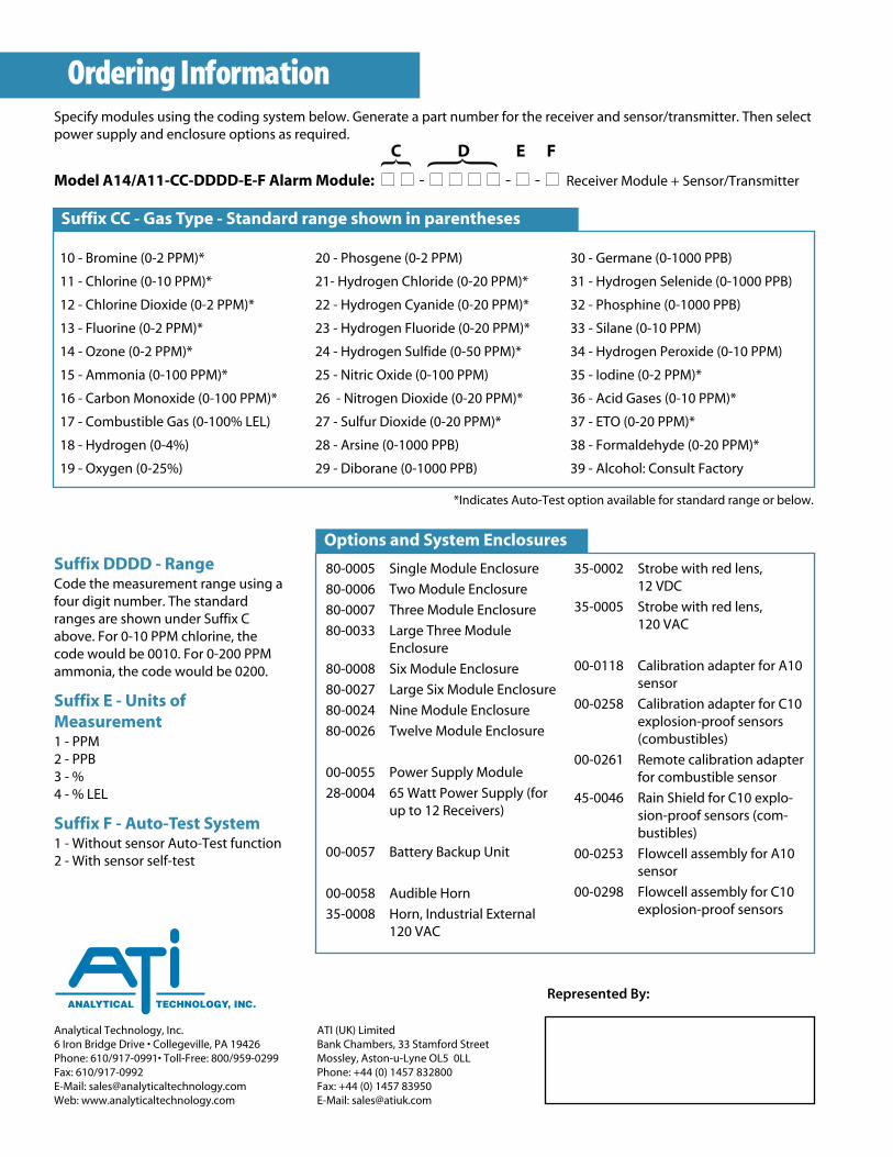
Specify modules using the coding system below. Generate a part number for the receiver and sensor/transmitter. Then selectpower supply and enclosure options as required.
Model A14/A11-CC-DDDD-E-F Alarm Module: ■■ ■■ - ■■ ■■ ■■ ■■ - ■■ - ■■ Receiver Module + Sensor/Transmitter
10 - Bromine (0-2 PPM)*
11 - Chlorine (0-10 PPM)*
12 - Chlorine Dioxide (0-2 PPM)*
13 - Fluorine (0-2 PPM)*
14 - Ozone (0-2 PPM)*
15 - Ammonia (0-100 PPM)*
16 - Carbon Monoxide (0-100 PPM)*
17 - Combustible Gas (0-100% LEL)
18 - Hydrogen (0-4%)
19 - Oxygen (0-25%)
20 - Phosgene (0-2 PPM)
21- Hydrogen Chloride (0-20 PPM)*
22 - Hydrogen Cyanide (0-20 PPM)*
23 - Hydrogen Fluoride (0-20 PPM)*
24 - Hydrogen Sulfide (0-50 PPM)*
25 - Nitric Oxide (0-100 PPM)
26 - Nitrogen Dioxide (0-20 PPM)*
27 - Sulfur Dioxide (0-20 PPM)*
28 - Arsine (0-1000 PPB)
29 - Diborane (0-1000 PPB)
30 - Germane (0-1000 PPB)
31 - Hydrogen Selenide (0-1000 PPB)
32 - Phosphine (0-1000 PPB)
33 - Silane (0-10 PPM)
34 - Hydrogen Peroxide (0-10 PPM)
35 - Iodine (0-2 PPM)*
36 - Acid Gases (0-10 PPM)*
37 - ETO (0-20 PPM)*
38 - Formaldehyde (0-20 PPM)*
39 - Alcohol: Consult Factory
Suffix DDDD - RangeCode the measurement range using afour digit number. The standardranges are shown under Suffix Cabove. For 0-10 PPM chlorine, thecode would be 0010. For 0-200 PPMammonia, the code would be 0200.
Suffix E - Units ofMeasurement1 - PPM2 - PPB3 - %4 - % LEL
Suffix F - Auto-Test System1 - Without sensor Auto-Test function2 - With sensor self-test
Ordering Information
Suffix CC - Gas Type - Standard range shown in parentheses
Options and System Enclosures
80-0005 Single Module Enclosure
80-0006 Two Module Enclosure
80-0007 Three Module Enclosure
80-0033 Large Three ModuleEnclosure
80-0008 Six Module Enclosure
80-0027 Large Six Module Enclosure
80-0024 Nine Module Enclosure
80-0026 Twelve Module Enclosure
00-0055 Power Supply Module
28-0004 65 Watt Power Supply (forup to 12 Receivers)
00-0057 Battery Backup Unit
00-0058 Audible Horn
35-0008 Horn, Industrial External 120 VAC
35-0002 Strobe with red lens, 12 VDC
35-0005 Strobe with red lens, 120 VAC
00-0118 Calibration adapter for A10sensor
00-0258 Calibration adapter for C10explosion-proof sensors(combustibles)
00-0261 Remote calibration adapterfor combustible sensor
45-0046 Rain Shield for C10 explo-sion-proof sensors (com-bustibles)
00-0253 Flowcell assembly for A10sensor
00-0298 Flowcell assembly for C10explosion-proof sensors
C D E F
*Indicates Auto-Test option available for standard range or below.
Represented By:


![DDS C ,bc ]^ - NEDO · DDS ˘ˇˆ ... DSBL 3.70 ppm DSBL 1.23 ppm BC 100.00 ppm BC 33.33 ppm BC 11.11 ppm BC 3.70 ppm BC 1.23 ppm DMCBL 100.00 ppm DMCBL 33.33 ppm DMCBL 11.11 ppm](https://img.dokumen.tips/doc/110x75/5ad6c02a7f8b9a6d708e8ad8/dds-c-bc-dsbl-370-ppm-dsbl-123-ppm-bc-10000-ppm-bc-3333-ppm.jpg)


 ②0.000~0.7[ppm]( 検出下限値:0.065) ポータブル型](https://img.dokumen.tips/doc/110x75/5fecdf9984c5493c976b486c/gas-detector-foec-midas-t-004-eee-a0000i04ppmi.jpg)


![DDS C ,bc ]^ · 17 % cell growth DMBL 100.00 ppm DMBL 33.33 ppm DMBL 11.11 ppm control DMBL 3.70 ppm DMBL 1.23 ppm DPBL 100.00 ppm DPBL 33.33 ppm DPBL 11.11 ppm DPBL 3.70 ppmDPBL](https://img.dokumen.tips/doc/110x75/5e775a5ea36baa321a57d8d8/dds-c-bc-17-cell-growth-dmbl-10000-ppm-dmbl-3333-ppm-dmbl-1111-ppm-control.jpg)