Embed Size (px)
Citation preview

Modular F.R.L.Pressure Control Equipment
AC-A
AC-B
ACG
AF10-A to AF60-A
AFM20-A to AFM40-A
AFD20-A to AFD40-A
AR10-A to AR40-A
AR20-B to AR60-B
AR20K-B to AR60K-B
AL10-A to AL60-A
AW10-A to AW40-A
AW20-B to AW60-B
AW20K-B to AW60K-B
AWM20 to AWM40
AWD20 to AWD40
ARG20(K)/30(K)/40(K)
AWG20/30/40
AWG20K/30K/40K
AR425 to 935
AMR3000 to 6000
ARM5A
ARM5B
ARM5S
ARM10
ARM11A
ARM11B
ARM11A/B
Air Combination
Air Combination
Air Combination
Air Filter
Mist Separator
Micro Mist Separator
Regulator
Regulator
Regulator with Backflow Function
Lubricator
Filter Regulator
Filter Regulator
Filter Regulator with Backflow Function
Mist Separator Regulator
Micro Mist Separator Regulator
Regulator with Built-in Pressure Gauge
Filter Regulator with Built-in Pressure Gauge
Filter Regulator with Built-in Pressure Gauge with Backflow Function
Pilot Operated Regulator
MR Unit (Regulator with Mist Separator)
Compact Manifold Regulator/Centralized Supply Type
Compact Manifold Regulator/Individual Supply Type
Regulator/Single Unit Type
Regulator/Single Unit Type
Compact Manifold Regulator/Common Supply Type
Compact Manifold Regulator/Individual Supply Type
Compact Manifold Regulator/Options
p. 249p. 250p. 251p. 253p. 254p. 254p. 255p. 256p. 256p. 257p. 258p. 259p. 259p. 260p. 260p. 261p. 262p. 263p. 264p. 265p. 266p. 267p. 268p. 269p. 270p. 271p. 272
p. 431——
p. 434p. 445p. 447p. 449p. 454p. 456p. 461p. 469p. 485p. 488p. 497p. 503p. 509p. 515
—p. 522p. 526p. 527p. 527p. 527p. 531p. 531p. 531p. 531
3 Details of replacement parts
1 Indication of replacement of elements, inspection items p. 245
2 Troubleshooting p. 246
ReplacementParts
ReplacementProcedure
244
Act
uat
ors
Modu
lar F.R
.L.Pre
ssure
Contr
ol Eq
uipme
nt A
ir P
rep
arat
ion
Eq
uip
men
tIn
dust
rial
Filt
ers
Repl
acem
ent
Proc
edur
eA
ctu
ato
rsMo
dular
F.R.L.
Pressu
re Co
ntrol
Equip
ment
Indu
stri
al F
ilter
s

<Element replacement>The differential pressure (pressure drop) between the primary side and secondary side reaches 0.1 MPa.Even when any pressure differential does not occur, replace the element every two years.
Modular F.R.L. Pressure Control Equipment
The following describes the general contents of the element replacement and regular check.
1 Indication of replacement of elements, inspection items
Indication of replacement of air filter, inspection itemsReplacement standards
Check the set pressure level before starting up the equipment. If the set pressure level is beyond the speci-fied range, locate the cause.(Be sure to locate the cause before starting the readjustment.) Additionally, check the following points dur-ing periodic inspection.1) Functional inspection and grease-up of the valve body (including the valve guide)2) Functional inspection and grease-up of the valve spring
Check for rust, breakage, or permanent settling.3) Checking of setting function and relief function (Check the functions by increasing or decreasing
the setting.)
Regulator inspection itemsInspection items
q Inspection of dripping volume: Inspect this item when starting the equipment operation.w Check the oil status inside the case. Check for drain entry.e Check for air leak inside the case or air backflow on the secondary side.
Lubricator inspection itemsInspection items
Refer to the "Troubleshooting" for air filter/auto drain. (p. 246)
Probable troubles (Reference)
Refer to the "Troubleshooting" for regulator. (p. 247)
Probable troubles (Reference)
Refer to the "Troubleshooting" for lubricator. (p. 248)
Probable troubles (Reference)
1) Checking of external leak or case crack.If the case is cracked, this may lead to a serious accident, such as case rupture. So, replace the case im-mediately and locate the cause. If the case is contaminated significantly and the internal status cannot be checked, clean the case with neutral detergent. At this time, never use solvent or machine cleaning solu-tion.
2) Functional inspection of drain discharge mechanismCheck that the drain mechanism functions correctly without fail and that the drain is discharged periodi-cally for manual type.If the drain is produced excessively, a trouble may occur in the purification equipment on the upstream side.
Inspection items
245

[Air filter/Auto drain]Corrective actionCauseTrouble (Symptom)
1. Replace the element.1. The element is clogged.
1. Replace the bowl O-ring.Apply the grease to the bowl O-ring, and then assemble it into the bowl.
1. The bowl O-ring is damaged.
1. Replace the bowl assembly or replace the bowl with a metallic bowl.
1. The bowl is damaged.
1. Open the drain cock for several sec-onds to blow out the foreign object.
2. Replace the bowl assembly.
1. Replace the bowl assembly.
1. Open the drain cock to discharge the drain, and then replace the element.
1. A foreign object is caught in the valve of the drain cock.
2. The drain cock seat is damaged.
1. The discharge port of the drain cock is clogged with solid foreign object.
1. The drain level exceeds the baffle.
The pressure drop is large and the specified flow rate cannot be obtained.
The air leaks from the portion between the bowl and body.
The air leaks from the bowl.
The air leaks from the drain cock.
The drain is not dis-charged even when the drain cock is opened.
An excessive amount of drain is discharged to the pipe at the outlet.
The following describes the general contents of the troubleshooting.
2 Troubleshooting
246
Act
uat
ors
Modu
lar F.R
.L.Pre
ssure
Contr
ol Eq
uipme
nt A
ir P
rep
arat
ion
Eq
uip
men
tIn
dust
rial
Filt
ers
Repl
acem
ent
Proc
edur
eA
ctu
ato
rsMo
dular
F.R.L.
Pressu
re Co
ntrol
Equip
ment
Indu
stri
al F
ilter
s
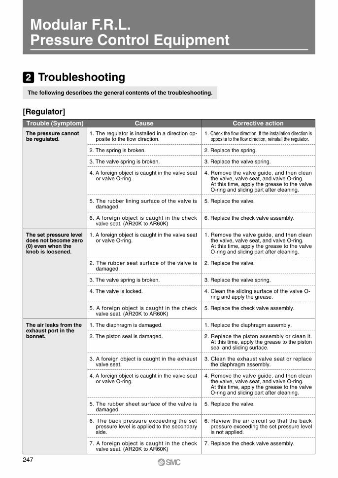
Corrective actionCauseTrouble (Symptom)
1. Check the flow direction. If the installation direction is opposite to the flow direction, reinstall the regulator.
2. Replace the spring.
3. Replace the valve spring.
4. Remove the valve guide, and then clean the valve, valve seat, and valve O-ring.At this time, apply the grease to the valve O-ring and sliding part after cleaning.
5. Replace the valve.
6. Replace the check valve assembly.
1. The regulator is installed in a direction op-posite to the flow direction.
2. The spring is broken.
3. The valve spring is broken.
4. A foreign object is caught in the valve seat or valve O-ring.
5. The rubber lining surface of the valve is damaged.
6. A foreign object is caught in the check valve seat. (AR20K to AR60K)
1. Remove the valve guide, and then clean the valve, valve seat, and valve O-ring.At this time, apply the grease to the valve O-ring and sliding part after cleaning.
2. Replace the valve.
3. Replace the valve spring.
4. Clean the sliding surface of the valve O-ring and apply the grease.
5. Replace the check valve assembly.
1. A foreign object is caught in the valve seat or valve O-ring.
2. The rubber seat surface of the valve is damaged.
3. The valve spring is broken.
4. The valve is locked.
5. A foreign object is caught in the check valve seat. (AR20K to AR60K)
1. Replace the diaphragm assembly.
2. Replace the piston assembly or clean it. At this time, apply the grease to the piston seal and sliding surface.
3. Clean the exhaust valve seat or replace the diaphragm assembly.
4. Remove the valve guide, and then clean the valve, valve seat, and valve O-ring.At this time, apply the grease to the valve O-ring and sliding part after cleaning.
5. Replace the valve.
6. Review the air circuit so that the back pressure exceeding the set pressure level is not applied.
7. Replace the check valve assembly.
1. The diaphragm is damaged.
2. The piston seal is damaged.
3. A foreign object is caught in the exhaust valve seat.
4. A foreign object is caught in the valve seat or valve O-ring.
5. The rubber sheet surface of the valve is damaged.
6. The back pressure exceeding the set pressure level is applied to the secondary side.
7. A foreign object is caught in the check valve seat. (AR20K to AR60K)
The pressure cannot be regulated.
The set pressure level does not become zero (0) even when the knob is loosened.
The air leaks from the exhaust port in the bonnet.
[Regulator]
The following describes the general contents of the troubleshooting.
2 Troubleshooting
Modular F.R.L.Pressure Control Equipment
247

[Lubricator]Corrective actionCauseTrouble (Symptom)
1. Check the “IN”, “OUT”, and arrow marks on the equipment. If any incorrect connection is found, connect the equipment again.
2. Supply the oil.
3. Select an appropriate lubricator with a minimum dripping flow rate suitable for the flow rate to be used.
4. Replace the damper (assembly).
5. Open the oil adjustment valve.
6. Replace the case O-ring or lubrication plug assembly.
7. Replace the damper pushing air assembly.
8. Replace the sight dome assembly.
1. The equipment is not connected correctly.
2. The oil volume inside the bowl is insuffi-cient.
3. The air consumption flow rate is insuffi-cient.
4. The damper is damaged.
5. The oil adjustment valve is closed.
6. The air leaks from the bowl or lubrication plug.
7. The element is clogged.
8. The air leaks from the sight dome.
1. Replace the damper retainer air assembly.
2. Supply the oil.
1. The oil passage pipe seal is damaged.
2. The oil volume inside the bowl is insufficient.
1. Replace the sight dome assembly.
2. Replace the sight dome assembly.
1. Replace the lubrication plug assembly.
1. Replace the bowl O-ring.Apply the grease to the bowl O-ring and assemble it into the bowl.
1. Replace the bowl assembly or replace the bowl with a metallic bowl.
1. The sight dome is damaged.
2. The O-ring is damaged.
1. The O-ring is damaged.
1. The bowl O-ring is damaged.
1. The bowl is damaged.
The oil does not drop even when the air flows.
Air bubbles are mixed in the oil drop.
The air or oil leaks from the sight glass.
The air leaks from the lubrication plug.
The air leaks from the portion between the bowl and body.
The air leaks from the bowl
[Regulator]Corrective actionCauseTrouble (Symptom)
1. Retighten the bonnet screw.
2. Replace the diaphragm assembly.
1. The bonnet screw is loose.
2. The diaphragm is damaged.
The air leaks from the portion between the bonnet and body.
1. Replace the check valve assembly.
2. Replace the check valve assembly.
1. A foreign object is caught in the sliding part of the check valve, causing malfunc-tion. (AR20K to AR60K)
2. The check valve is locked. (AR20K to AR60K)
The air does not flow backward.
248
Act
uat
ors
Modu
lar F.R
.L.Pre
ssure
Contr
ol Eq
uipme
nt A
ir P
rep
arat
ion
Eq
uip
men
tIn
dust
rial
Filt
ers
Repl
acem
ent
Proc
edur
eA
ctu
ato
rsMo
dular
F.R.L.
Pressu
re Co
ntrol
Equip
ment
Indu
stri
al F
ilter
s

Air Combination
AC-A Seriesp. 431
TheReplacement
Procedure is on
Air Filter + Regulator + Lubricator
Note 1) in round pressure gauge part numbers indicates a pipe thread type. No indication is necessary for R; however, indicate N for NPT.Please contact SMC regarding the pipe thread type NPT and the supply of pressure gauge with psi unit display specifications.
Note 2) Standard pressure gaugeNote 3) For F.R.L. units, port sizes without ( ) are standard specifications.Note 4) Separate spacers are required for modular unit.
Options/Attachments Part No.
Sec
tion
Type
Model
Options/Attachments part no.AC10-A AC20-A AC25-A AC30-A AC40-A AC40-06-A
AC10A-A AC20A-A — AC30A-A AC40A-A AC40A-06-AAC10B-A AC20B-A AC25B-A AC30B-A AC40B-A AC40B-06-A
— AC20C-A AC25C-A AC30C-A AC40C-A AC40C-06-A— AC20D-A — AC30D-A AC40D-A AC40D-06-A
Opt
ion
Pressu
re gaug
eNote
1)
Round type Standard G27-10-R1 G36-10-01 G46-10-010.02 to 0.2 MPa setting G27-10-R1 Note 2) G36-4-01 G46-4-01
Round type(with color zone)
Standard — G36-10-01-L G46-10-01-L0.02 to 0.2 MPa setting — G36-4-01-L G46-4-01-L
Atta
chm
ent
Spacer Y100-A Y200-A Y300-A Y400-A Y500-ASpacer with bracket Y100T-A Y200T-A Y300T-A Y400T-A Y500T-A
Check valve Note 3, 4) — AKM2000-01-A(02)-A
AKM3000-(01)-A02-A
AKM4000-(02)-A03-A
—
Pressure switch Note 4) — IS10M-20-A IS10M-30-A IS10M-40-A IS10M-50-A
T-spacer Note 3, 4) Y110-M5-A Y210-01-A(02)-A
Y310-(01)-A02-A
Y410-(02)-A03-A
Y510-(02)-A03-A
Pressure relief 3 port valve Note 4) — VHS20-01A
02AVHS30-02A
03A
02AVHS40-03A
04AVHS40-06A
Piping adapter Note 4) E100-M5-A01-A
E200-02-A03-A
02-AE300-03-A
04-A
02-AE400-03-A
04-A06-A
E500-06-A
Pressure switch with piping adapter Note 4) —
01-AIS10E-2002-A
03-A
02-AIS10E-3003-A
04-A
02-AIS10E-4003-A
04-A06-A
—
Cross spacer Note 4) Y14-M5-A Y24-01-A02-A
Y34-01-A02-A
Y44-02-A03-A
Y54-03-A04-A
AC10-A to AC40-A
249

Air Combination
AC-B SeriesS
ectio
n Model
Type
Options/Attachments part no.AC20-B AC25-B AC30-B AC40-B AC40-06-B AC50-B AC55-B AC60-B
AC20A-B — AC30A-B AC40A-B AC40A-06-B AC50A-B — AC60A-BAC20B-B AC25B-B AC30B-B AC40B-B AC40B-06-B AC50B-B AC55B-B AC60B-BAC20C-B AC25C-B AC30C-B AC40C-B AC40C-06-B — — —AC20D-B — AC30D-B AC40D-B AC40D-06-B — — —
Opt
ion
Pres
sure
gau
geNo
te 1
)
Round typeStandard G36-10-01 G46-10-01
0.02 to 0.2 MPa setting G36-4-01 G46-4-01Round type(with color zone)
Standard G36-10-01-L G46-10-01-L0.02 to 0.2 MPa setting G36-4-01-L G46-4-01-L
Square embedded type Note 2)
Standard GC3-10AS [GC3P-010AS (Pressure gauge cover only)]0.02 to 0.2 MPa setting GC3-4AS [GC3P-010AS (Pressure gauge cover only)]
Digital pressure switch
NPN output, Wiring bottom entry ISE35-N-25-MLA [ISE35-N-25-M (Switch body only)] Note 3)
NPN output, Wiring top entry ISE35-R-25-MLA [ISE35-R-25-M (Switch body only)] Note 3)
PNP output, Wiring bottom entry ISE35-N-65-MLA [ISE35-N-65-M (Switch body only)] Note 3)
PNP output, Wiring top entry ISE35-R-65-MLA [ISE35-R-65-M (Switch body only)] Note 3)
Float type auto drain Note 4)
N.O. — AD38-A AD48-AN.C. AD27-A AD37-A AD47-A
Atta
chm
ent
Spacer Y200-A Y300-A Y400-A Y500-A Y600-ASpacer with bracket Y200T-A Y300T-A Y400T-A Y500T-A Y600T-A
Check valve Note 5, 6) AKM2000-01-A(02)-A
AKM3000-(01)-A02-A
AKM4000-(02)-A03-A
— — — —
Pressure switch Note 6) IS10M-20-A IS10M-30-A IS10M-40-A IS10M-50-A IS10M-60-A
T-spacer Note 5, 6) Y210-01-A(02)-A
Y310-(01)-A02-A
Y410-(02)-A03-A
Y510-(02)-A03-A
Y610-03-A(04)-A
Y610-(03)-A04-A
Pressure relief 3 port valve Note 6) VHS20-01A02A
VHS30-02A03A
02AVHS40-03A
04AVHS40-06A
VHS50-06A10A
— —
Piping adapter Note 6)01-A
E200-02-A03-A
02-AE300-03-A
04-A
02-AE400-03-A
04-A06-A
E500-06-AE600-06-A
10-A
Pressure switch with piping adapter Note 6)
01-AIS10E-2002-A
03-A
02-AIS10E-3003-A
04-A
02-AIS10E-4003-A
04-A06-A
— — — —
Cross spacer Note 6) Y24-01-A02-A
Y34-01-A02-A
Y44-02-A03-A
Y54-03-A04-A
— — —
Options/Attachments Part No.
Note 1) in part numbers for a round type pressure gauge indicates a pipe thread type. No indication is necessary for R; however, indicate N for NPT. Please contact SMC regarding the connection thread NPT and pressure gauge supply for psi unit specifications.
Note 2) Including one O-ring and 2 mounting screwsNote 3) Lead wire with connector (2 m), adapter, lock pin, O-ring (1 pc.), mounting
screw (2 pcs.) are attached. [ ]: Switch body only.Also, regarding how to order the digital pressure switch, refer to the Web Catalog.
Note 4) Minimum operating pressure: N.O. type–0.1 MPa; N.C. type–0.1 MPa (AD27-A) and 0.15 MPa (AD37-A/AD47-A). Please consult with SMC separately for psi and °F unit display specifications.
Note 5) For F.R.L. units, port sizes without ( ) are standard specifications.Note 6) Separate spacers are required for modular unit.
Air Filter + Regulator + LubricatorAC20-B to AC60-B
250
Act
uat
ors
Modu
lar F.R
.L.Pre
ssure
Contr
ol Eq
uipme
nt A
ir P
rep
arat
ion
Eq
uip
men
tIn
dust
rial
Filt
ers
Repl
acem
ent
Proc
edur
eA
ctu
ato
rsMo
dular
F.R.L.
Pressu
re Co
ntrol
Equip
ment
Indu
stri
al F
ilter
s

Air Filter + Regulator + LubricatorACG20/30/40
Options/Attachments part no.
GB2-10ASGB2-3AS
AD27−
Y200Y200T
AKM2000-01, (02)IS10M-20
VHS20-01, 02
GB3-10ASGB3-3AS
AD37AD38Y300
Y300TAKM3000-(01), 02
IS10M-30VHS30-02, 03
GB4-10ASGB4-3AS
AD47AD48Y400
Y400TAKM4000-(02), 03
IS10M-40VHS40-02, 03, 04
Options/Attachments Part No.
ACG20 ACG30 ACG40
Note 1) Contact SMC regarding pressure gauge supply for psi unit specifications.Note 2) Minimum operating pressure: 0.1 MPa for N.O. type, 0.1 MPa for N.C. type (AD27) and 0.15 MPa for N.C. type (AD37 and 47). Contact SMC for psi
and °F specifications.Note 3) For F.R.L. units, port sizes not in ( ) are for standard application.Note 4) Separate spacers are required for modular unit.Note 5) Pressure switch cannot be mounted on the inlet and outlet sides of an ARG with an upward facing knob (optional specification: -Y).
ModelDescription
SpacerSpacer with bracketCheck valve Note 3, 4)
Pressure switch Note 4, 5)
Residual pressure relief 3 port valve Note 4)
Float type auto drain Note 2)
0 to 1.0 MPa0 to 0.3 MPa
StandardOptional
N.C.N.O.
Pressure gauge Note 1)
Atta
chm
ents
Optio
ns
ACG20B/30B/40B
Options/Attachments part no.
GB2-10ASGB2-3AS
AD27−
Y200Y200T
IS10M-20VHS20-01, 02
GB3-10ASGB3-3AS
AD37AD38Y300
Y300TIS10M-30
VHS30-02, 03
GB4-10ASGB4-3AS
AD47AD48Y400
Y400TIS10M-40
VHS40-02, 03, 04
ACG20B ACG30B ACG40BModelDescription
SpacerSpacer with bracketPressure switch Note 3, 4)
Residual pressure relief 3 port valve Note 3)
Float type auto drain Note 2)
0 to 1.0 MPa0 to 0.3 MPa
StandardOptional
N.C.N.O.
Pressure gauge Note 1)
Atta
chm
ents
Note 1) Contact SMC regarding pressure gauge supply for psi unit specifications.Note 2) Minimum operating pressure: 0.1 MPa for N.O. type, 0.1 MPa for N.C. type (AD27) and 0.15 MPa for N.C. type (AD37 and 47). Contact SMC for psi
and °F specifications.Note 3) Separate spacers are required for modular unit.Note 4) Pressure switch cannot be mounted on the inlet and outlet sides of an ARG with an upward facing knob (optional specification: -Y).
Air Filter + Regulator
Options/Attachments Part No.
Optio
ns
Note 1) Contact SMC regarding pressure gauge supply for psi unit specifications.Note 2) Minimum operating pressure: 0.1 MPa for N.O. type, 0.1 MPa for N.C. type (AD27) and 0.15 MPa for N.C. type (AD37 and 47). Contact SMC for psi
and °F specifications.Note 3) For F.R.L. units, port sizes not in ( ) are for standard application.Note 4) Separate spacers are required for modular unit.
Filter Regulator + LubricatorACG20A/30A/40A
Options/Attachments part no.
GB2-10ASGB2-3AS
AD27−
Y200Y200T
AKM2000-01, (02)VHS20-01, 02
GB3-10ASGB3-3AS
AD37AD38Y300
Y300TAKM3000-(01), 02
VHS30-02, 03
GB4-10ASGB4-3AS
AD47AD48Y400
Y400TAKM4000-(02), 03
VHS40-02, 03, 04
Options/Attachments Part No.
ACG20A ACG30A ACG40AModelDescription
Spacer Note 3, 4)
Spacer with bracketCheck valveResidual pressure relief 3 port valve Note 4)
Float type auto drain Note 2)
0 to 1.0 MPa0 to 0.3 MPa
StandardOptional
N.C.N.O.
Pressure gauge Note 1)
Atta
chm
ents
Optio
ns
ACG SeriesAir Combination
251

ACG20C/30C/40C
Options/Attachments part no.
GB2-10ASGB2-3AS
AD27−
Y200Y200T
IS10M-20VHS20-01, 02
GB3-10ASGB3-3AS
AD37AD38Y300
Y300TIS10M-30
VHS30-02, 03
GB4-10ASGB4-3AS
AD47AD48Y400
Y400TIS10M-40
VHS40-02, 03, 04
ACG20C ACG30C ACG40CModelDescription
SpacerSpacer with bracketPressure switch Note 3, 4)
Residual pressure relief 3 port valve Note 3)
Float type auto drain Note 2)
0 to 1.0 MPa0 to 0.3 MPa
StandardOptional
N.C.N.O.
Pressure gauge Note 1)
Atta
chm
ents
Note 1) Contact SMC regarding pressure gauge supply for psi unit specifications.Note 2) Minimum operating pressure: 0.1 MPa for N.O. type, 0.1 MPa for N.C. type (AD27) and 0.15 MPa for N.C. type (AD37 and 47). Contact SMC for psi
and °F specifications.Note 3) Separate spacers are required for modular unit.Note 4) Pressure switch cannot be mounted on the inlet and outlet sides of an ARG with an upward facing knob (optional specification: -Y).
Air Filter + Mist Separator + Regulator
Options/Attachments Part No.
Options/Attachments part no.
GB2-10ASGB2-3AS
AD27−
Y200Y200T
VHS20-01, 02
GB3-10ASGB3-3AS
AD37AD38Y300
Y300TVHS30-02, 03
GB4-10ASGB4-3AS
AD47AD48Y400
Y400TVHS40-02, 03, 04
ACG20D ACG30D ACG40DModelDescription
SpacerSpacer with bracketResidual pressure relief 3 port valve Note 3)
Float type auto drain Note 2)
0 to 1.0 MPa0 to 0.3 MPa
StandardOptional
N.C.N.O.
Pressure gauge Note 1)
Attach
ments
Note 1) Contact SMC regarding pressure gauge supply for psi unit specifications.Note 2) Minimum operating pressure: 0.1 MPa for N.O. type, 0.1 MPa for N.C. type (AD27) and 0.15 MPa for N.C. type (AD37 and 47). Contact SMC for psi
and °F specifications.Note 3) Separate spacers are required for modular unit.
Filter Regulator + Mist SeparatorACG20D/30D/40DOptions/Attachments Part No.
Optio
nsOp
tions
Air Combination
ACG Series
252
Act
uat
ors
Modu
lar F.R
.L.Pre
ssure
Contr
ol Eq
uipme
nt A
ir P
rep
arat
ion
Eq
uip
men
tIn
dust
rial
Filt
ers
Repl
acem
ent
Proc
edur
eA
ctu
ato
rsMo
dular
F.R.L.
Pressu
re Co
ntrol
Equip
ment
Indu
stri
al F
ilter
s

OUTIN
Drain
w
e
t
r
OUTIN
Drain
w
e
t
r
OUTIN
r
w
e
t
Drain
AF10-A to AF60-AAir Filter
p. 434
TheReplacement
Procedure is on
Bowl Assembly Part No.
Bowl material
Drain discharge
mechanismDrain port Other
Model
AF10-A AF20-A AF30-A AF40-A AF40-06-A AF50-A AF60-A
Polycarbo-nate
Manualdischarge
With drain cock— C1SF-A C2SF-A — —
With bowl guard — C2SF-C-A C3SF-A C4SF-A
Drain cock with barb fitting With bowl guard — — C3SF-W-A C4SF-W-A
With drain guide(without valve function)
— — C2SF-J-A — —
With bowl guard — C2SF-CJ-A C3SF-J-A C4SF-J-A
Note)Automatic discharge
(Auto drain)
Normally closed (N.C.)— AD17-A AD27-A — —
With bowl guard — AD27-C-A AD37-A AD47-A
Normally open (N.O.) With bowl guard — — AD38-A AD48-A
Nylon
Manualdischarge
With drain cock— C1SF-6-A C2SF-6-A — —
With bowl guard — C2SF-6C-A C3SF-6-A C4SF-6-A
Drain cock with barb fitting With bowl guard — — C3SF-6W-A C4SF-6W-A
With drain guide(without valve function)
— — C2SF-6J-A — —
With bowl guard — C2SF-6CJ-A C3SF-6J-A C4SF-6J-A
Note)Automatic discharge
(Auto drain)
Normally closed (N.C.)— AD17-6-A AD27-6-A — —
With bowl guard — AD27-6C-A AD37-6-A AD47-6-A
Normally open (N.O.) With bowl guard — — AD38-6-A AD48-6-A
Metal
Manualdischarge
With drain cock— C1SF-2-A C2SF-2-A C3SF-2-A C4SF-2-A
With level gauge — — C3LF-8-A C4LF-8-A
With drain guide(without valve function)
— — C2SF-2J-A C3SF-2J-A C4SF-2J-A
With level gauge — — C3LF-8J-A C4LF-8J-A
Note)Automatic discharge
(Auto drain)
Normally closed (N.C.)— AD17-2-A AD27-2-A AD37-2-A AD47-2-A
With level gauge — — AD37-8-A AD47-8-A
Normally open (N.O.)— — — AD38-2-A AD48-2-A
With level gauge — — AD38-8-A AD48-8-A
Note) Minimum operating pressure: N.O. type–0.1 MPa (AD38-A, AD48-A); N.C. type–0.1 MPa (AD17-A, AD27-A) and 0.15 MPa (AD37-A, AD47-A).Bowl assembly for the AF20-A to AF60-A models comes with a bowl seal. in bowl assembly part numbers indicates a pipe thread type (applicable tubing for auto drain).No indication is necessary for Rc thread; however, indicate N for NPT thread, and F for G thread. (For auto drain, Nil: ø10, N: ø3/8")Please consult with SMC separately for psi and °F unit display specifications.
Replacement Parts
No. Description MaterialPart no.
AF10-A AF20-A AF30-A AF40-A AF40-06-A AF50-A AF60-Aw Filter element Non-woven fabric AF10P-060S AF20P-060S AF30P-060S AF40P-060S AF50P-060S AF60P-060S
e Baffle PBT AF10P-040S Note 2) AF22P-040S AF32P-040S AF42P-040S AF50P-040S AF60P-040S
r Bowl seal NBR C1SFP-260S C2SFP-260S C32FP-260S C42FP-260S
t Bowl assembly Note 1) Polycarbonate C1SF-A C2SF-A C3SF-A C4SF-A
Note 1) Bowl seal is included for the AF20-A to AF60-A. Please contact SMC regarding the supply of bowl assembly with psi and °F unit display specifications.
Note 2) The baffle material for the AF10-A (AF10P-040S) only is polyacetal.
Options/Part No.
Optional specificationsModel
AF10-A AF20-A AF30-A AF40-A AF40-06-A AF50-A AF60-ABracket assembly
Note) — AF22P-050AS AF32P-050AS AF42P-050AS AF42P-070AS AF52P-050AS
Note) Assembly of a bracket and 2 mounting screws
Construction
AF10-A/AF20-A
AF30-A to AF40-06-A
AF50-A/AF60-A
* The numbers correspond with those in the “Construction” of the AF series in the Best Pneumatics catalog.
253
e
w
r
OUTIN
Drain
e
w
r
OUTIN
Drain
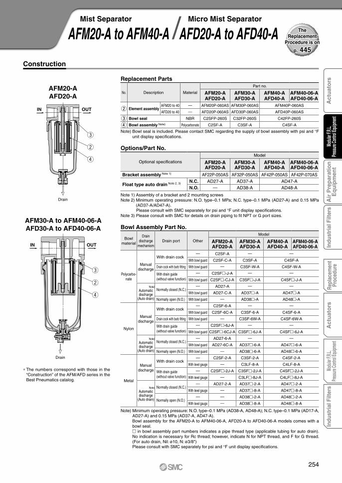
AFM20-A to AFM40-AMist Separator
AFD20-A to AFD40-AMicro Mist Separator/
p. 445
TheReplacement
Procedure is on
Bowl Assembly Part No.
Bowl material
Draindischarge
mechanismDrain port Other
Model
AFM20-AAFD20-A
AFM30-AAFD30-A
AFM40-AAFD40-A
AFM40-06-AAFD40-06-A
Polycarbo-nate
Manualdischarge
With drain cock— C2SF-A — —
With bowl guard C2SF-C-A C3SF-A C4SF-A
Drain cock with barb fitting With bowl guard — C3SF-W-A C4SF-W-A
With drain guide(without valve function)
— C2SF-J-A — —
With bowl guard C2SF-CJ-A C3SF-J-A C4SF-J-A
Note) Automatic discharge
(Auto drain)
Normally closed (N.C.)— AD27-A — —
With bowl guard AD27-C-A AD37-A AD47-A
Normally open (N.O.) With bowl guard — AD38-A AD48-A
Nylon
Manualdischarge
With drain cock— C2SF-6-A — —
With bowl guard C2SF-6C-A C3SF-6-A C4SF-6-A
Drain cock with barb fitting With bowl guard — C3SF-6W-A C4SF-6W-A
With drain guide(without valve function)
— C2SF-6J-A — —
With bowl guard C2SF-6CJ-A C3SF-6J-A C4SF-6J-A
Note) Automatic discharge
(Auto drain)
Normally closed (N.C.)— AD27-6-A — —
With bowl guard AD27-6C-A AD37-6-A AD47-6-A
Normally open (N.O.) With bowl guard — AD38-6-A AD48-6-A
Metal
Manualdischarge
With drain cock— C2SF-2-A C3SF-2-A C4SF-2-A
With level gauge — C3LF-8-A C4LF-8-A
With drain guide(without valve function)
— C2SF-2J-A C3SF-2J-A C4SF-2J-A
With level gauge — C3LF-8J-A C4LF-8J-A
Note)Automatic discharge
(Auto drain)
Normally closed (N.C.)— AD27-2-A AD37-2-A AD47-2-A
With level gauge — AD37-8-A AD47-8-A
Normally open (N.O.)— — AD38-2-A AD48-2-A
With level gauge — AD38-8-A AD48-8-A
Note) Minimum operating pressure: N.O. type–0.1 MPa (AD38-A, AD48-A); N.C. type–0.1 MPa (AD17-A, AD27-A) and 0.15 MPa (AD37-A, AD47-A).Bowl assembly for the AFM20-A to AFM40-06-A, AFD20-A to AFD40-06-A models comes with a bowl seal. in bowl assembly part numbers indicates a pipe thread type (applicable tubing for auto drain). No indication is necessary for Rc thread; however, indicate N for NPT thread, and F for G thread. (For auto drain, Nil: ø10, N: ø3/8")Please consult with SMC separately for psi and °F unit display specifications.
Options/Part No.
Optional specifications
Model
AFM20-AAFD20-A
AFM30-AAFD30-A
AFM40-AAFD40-A
AFM40-06-AAFD40-06-A
Bracket assembly Note 1) AF22P-050AS AF32P-050AS AF42P-050AS AF42P-070AS
Float type auto drain Note 2, 3) N.C. AD27-A AD37-A AD47-A
N.O. — AD38-A AD48-A
Note 1) Assembly of a bracket and 2 mounting screwsNote 2) Minimum operating pressure: N.O. type–0.1 MPa; N.C. type–0.1 MPa (AD27-A) and 0.15 MPa
(AD37-A/AD47-A).Please consult with SMC separately for psi and °F unit display specifications.
Note 3) Please consult with SMC for details on drain piping to fit NPT or G port sizes.
Note) Bowl seal is included. Please contact SMC regarding the supply of bowl assembly with psi and °F unit display specifications.
Replacement Parts
No. Description Material
Part no.
AFM20-AAFD20-A
AFM30-AAFD30-A
AFM40-AAFD40-A
AFM40-06-AAFD40-06-A
w Element assemblyAFM20 to 40 — AFM20P-060AS AFM30P-060AS AFM40P-060AS
AFD20 to 40 — AFD20P-060AS AFD30P-060AS AFD40P-060AS
e Bowl seal NBR C2SFP-260S C32FP-260S C42FP-260S
r Bowl assembly Note) Polycarbonate C2SF-A C3SF-A C4SF-A
Construction
AFM20-AAFD20-A
AFM30-A to AFM40-06-AAFD30-A to AFD40-06-A
* The numbers correspond with those in the “Construction” of the AFM/AFD series in the Best Pneumatics catalog.
254
Act
uat
ors
Modu
lar F.R
.L.Pre
ssure
Contr
ol Eq
uipme
nt A
ir P
rep
arat
ion
Eq
uip
men
tIn
dust
rial
Filt
ers
Repl
acem
ent
Proc
edur
eA
ctu
ato
rsMo
dular
F.R.L.
Pressu
re Co
ntrol
Equip
ment
Indu
stri
al F
ilter
s

t
e
te
r
IN OUT
IN OUT
r
AR10-A to AR40-ARegulator
p. 449
TheReplacement
Procedure is on
AR10-A
AR20-A to 40-06-A
Note) The AR10-A is a piston type. Assembly of a piston and a seal (KSYP-13).
Replacement Parts
No. Description MaterialPart no.
AR10-A AR20-A AR25-A AR30-A AR40-A AR40-06-Ae Valve assembly Stainless steel/HNBR AR10P-090S AR22P-060AS AR32P-060AS AR42P-060AS
r Diaphragm assembly Weatherable NBR AR10P-150AS Note) AR22P-150AS AR32P-150AS AR42P-150AS
t Valve guide assembly Polyacetal 131329 AR22P-050AS AR32P-050AS AR42P-050AS
Construction
Note 1) Assembly of a bracket and set nutsNote 2) in round pressure gauge part numbers indicates a pipe thread type. No indication is necessary
for R; however, indicate N for NPT.Please contact SMC regarding the pipe thread type NPT and the supply of pressure gauge with psi unit display specifications.
Note 3) Standard pressure gauge
Options/Part No.
Optional specificationsModel
AR10-A AR20-A AR25-A AR30-A AR40-A AR40-06-ABracket assembly Note 1) AR12P-270AS AR22P-270AS AR27P-270AS AR32P-270AS AR42P-270AS AR42P-270AS
Set nut AR12P-260S AR22P-260S AR22P-260S AR32P-260S AR42P-260S AR42P-260S
Pressure gauge
Round type Note 2)
Standard G27-10-R1 G36-10-01 G46-10-01
0.02 to 0.2 MPa setting G27-10-R1 Note 3) G36-4-01 G46-4-01
Round type (with color zone) Note 2)
Standard — G36-10-01-L G46-10-01-L
0.02 to 0.2 MPa setting — G36-4-01-L G46-4-01-L
* The numbers correspond with those in the “Construction” of the AR series in the Best Pneumatics catalog.
255

t
e
r
IN OUT
t
e
r
IN OUT
t
e
r
IN OUT
A-AyA
CSM
2O
UT
1I N
A
AR20-B to AR60-BRegulator /AR20K-B to AR60K-B
Regulator with Backflow Function
p. 454
TheReplacement
Procedure is on
AR20(K)-B/AR25(K)-B AR30(K)-B/AR40(K)-B
AR20K-B to AR60K-B (Regulator with Backflow Function)
AR50(K)-B/AR60(K)-B
No. Description MaterialPart no.
AR20(K)-B AR25(K)-B AR30(K)-B AR40(K)-B AR40(K)-06-B AR50(K)-B AR60(K)-B
e Valve Brass/HNBR AR20P-410S AR25P-410S AR30P-410S AR40P-410S AR50P-410S AR60P-410S
r Diaphragm assembly Weatherable NBR AR20P-150AS AR25P-150AS AR30P-150AS AR40P-150AS AR50P-150AS
t Valve guide assembly Polyacetal AR20P-050AS AR25P-050AS AR30P-050AS AR40P-050AS AR50P-050AS AR60P-050AS
y Check valve assembly Note) — AR23KP-020AS
Note) Check valve assembly is applicable for a regulator with backflow function (AR20K-B to AR60K-B) only. Assembly of a check valve cover, check valve body assembly and 2 mounting screws
Construction
Note 1) Assembly of a bracket and set nuts. Including 2 mounting screws for the AR50(K)-B and AR60(K)-BNote 2) Please consult with SMC regarding the set nuts for the AR50(K)-B and AR60(K)-B.Note 3) in part numbers for a round pressure gauge indicates a pipe thread type. No indication is necessary for R; however, indicate N for NPT.
Please contact SMC regarding the pressure gauge supply for psi unit specifications.Note 4) Including one O-ring and 2 mounting screws. [ ]: Pressure gauge cover onlyNote 5) In addition to the pressure switch body, lead wire with connector (2 m), adapter, lock pin, O-ring (1 pc.), mounting screw (2 pcs.) are attached.
[ ]: Switch body only. (Regarding how to order the digital pressure switch, refer to the Web Catalog.)
Options/Part No.
Replacement Parts
Option Model AR20(K)-B AR25(K)-B AR30(K)-B AR40(K)-B AR40(K)-06-B AR50(K)-B AR60(K)-B
Bracket assembly Note 1) AR23P-270AS AR28P-270AS AR33P-270AS AR43P-270AS AR52P-270AS
Set nut AR23P-260S AR28P-260S AR33P-260S AR43P-260S — Note 2)
Pre
ssu
re g
aug
e Round type Note 3)Standard G36-10-01 G46-10-01
0.02 to 0.2 MPa setting G36-4-01 G46-4-01
Round type (with color zone) Note 3)
Standard G36-10-01-L G46-10-01-L
0.02 to 0.2 MPa setting G36-4-01-L G46-4-01-L
Squareembedded type Note 4)
Standard GC3-10AS [GC3P-010AS (Pressure gauge cover only)]
0.02 to 0.2 MPa setting GC3-4AS [GC3P-010AS (Pressure gauge cover only)]
Digital pressure switch Note 5)
NPN output, Wiring bottom entry ISE35-N-25-MLA [ISE35-N-25-M (Switch body only)]
NPN output, Wiring top entry ISE35-R-25-MLA [ISE35-R-25-M (Switch body only)]
PNP output, Wiring bottom entry ISE35-N-65-MLA [ISE35-N-65-M (Switch body only)]
PNP output, Wiring top entry ISE35-R-65-MLA [ISE35-R-65-M (Switch body only)]
* The numbers correspond with those in the “Construction” of the AR series in the Best Pneumatics catalog.
256
Act
uat
ors
Modu
lar F.R
.L.Pre
ssure
Contr
ol Eq
uipme
nt A
ir P
rep
arat
ion
Eq
uip
men
tIn
dust
rial
Filt
ers
Repl
acem
ent
Proc
edur
eA
ctu
ato
rsMo
dular
F.R.L.
Pressu
re Co
ntrol
Equip
ment
Indu
stri
al F
ilter
s

w
t
e
y
u
IN OUT
w
t e
ryu
IN OUT
r
w
t
yru
e
OUTIN
w
yu
OUTIN
AL10-A to AL60-ALubricator
p. 461
TheReplacement
Procedure is on
Bowl Assembly Part No.
Bowl material
Lubricantexhaust port
Other
Model
AL10-A AL20-A AL30-A AL40-A AL40-06-A AL50-A AL60-A
Polycarbo-nate
Without drain cock— C1SL-A C2SL-A — —
With bowl guard — C2SL-C-A C3SL-A C4SL-A
With drain cock— C1SL-3-A C2SL-3-A — —
With bowl guard — C2SL-3C-A C3SL-3-A C4SL-3-A
Drain cock with barb fitting With bowl guard — — C3SL-3W-A C4SL-3W-A
Nylon
Without drain cock— C1SL-6-A C2SL-6-A — —
With bowl guard — C2SL-6C-A C3SL-6-A C4SL-6-A
With drain cock— C1SL-36-A C2SL-36-A — —
With bowl guard — C2SL-36C-A C3SL-36-A C4SL-36-A
Drain cock with barb fitting With bowl guard — — C3SL-36W-A C4SL-36W-A
Metal
Without drain cock— C1SL-2-A C2SL-2-A C3SL-2-A C4SL-2-A
With level gauge — — C3LL-8-A C4LL-8-A
With drain cock— C1SL-23-A C2SL-23-A C3SL-23-A C4SL-23-A
With level gauge — — C3LL-38-A C4LL-38-A
Note) · Bowl seal is included for the AL20-A to AL60-A.· Please consult with SMC separately for psi and °F unit display specifications.
Note) Assembly of a bracket and 2 mounting screws
Options/Part No.
Optional specificationsModel
AL10-A AL20-A AL30-A AL40-A AL40-06-A AL50-A AL60-ABracket assembly
Note) — AF22P-050AS AF32P-050AS AF42P-050AS AF42P-070AS AF52P-050AS
Note) · Bowl seal is included for the AL20-A to AL60-A. Please consult with SMC separately for psi and °F unit display specifications.
· Bowl assembly for the AL30-A to AL60-A models comes with a bowl guard (Material: Polycarbonate).
Replacement Parts
No. Description MaterialPart no.
AL10-A AL20-A AL30-A AL40-A AL40-06-A AL50-A AL60-Aw Sight dome assembly Polycarbonate AL10P-080AS AL20P-080AS
e Lubrication plug assembly — — AL22P-060AS AL32P-060AS AL42P-060AS
r Bumper retainer assembly — — AL20P-030AS AL30P-030AS AL40P-030AS AL50P-030AS AL60P-030AS
t Bumper (assembly) Synthetic resin — AL20P-040S AL30P-040S AL40P-040S AL50P-040AS AL60P-040AS
y Bowl seal NBR C1SFP-260S C2SFP-260S C32FP-260S C42FP-260S
u Bowl assembly Note) Polycarbonate C1SL-A C2SL-A C3SL-A C4SL-A
AL10-A
AL20-A
AL30-A/AL40-A
AL50-A/AL60-A
Construction
* The numbers correspond with those in the “Construction” of the AL series in the Best Pneumatics catalog.
257

t
yeru
IN OUT
Drain
t
y
e
r
u
IN OUT
Drain
t
i
y
r
u
IN OUT
Drain
AW10-A to AW40-AFilter Regulator
p. 469
TheReplacement
Procedure is on
Replacement Parts
No. Description MaterialPart no.
AW10-A AW20-A AW30-A AW40-A AW40-06-Ae Valve assembly Stainless steel/HNBR AR10P-090S AW22P-060AS AW32P-060AS AW42P-060AS
r Filter element Non-woven fabric AF10P-060S AF20P-060S AF30P-060S AF40P-060S
t Diaphragm assembly Weatherable NBR AR10P-150AS Note 1) AR22P-150AS AR32P-150AS AR42P-150AS
y Bowl seal NBR C1SFP-260S C2SFP-260S C32FP-260S C42FP-260S
u Bowl assembly Note 2) Polycarbonate C1SF-A C2SF-A C3SF-A C4SF-A
Note 1) The AW10-A is a piston type. Assembly of a piston and a seal (KSYP-13).Note 2) Bowl seal is included for the AW20-A to AW40-06-A. Please contact SMC regarding the supply
of bowl assembly with psi and °F unit display specifications.
AW10-A
AW30-A to AW40-06-A
Bowl Assembly Part No.
Bowl material
Draindischarge
mechanismDrain port Other
Model
AW10-A AW20-A AW30-A AW40-A AW40-06-A
Polycarbo-nate
Manualdischarge
With drain cock— C1SF-A C2SF-A — —
With bowl guard — C2SF-C-A C3SF-A C4SF-A
Drain cock with barb fitting With bowl guard — — C3SF-W-A C4SF-W-A
With drain guide(without valve function)
— — C2SF-J-A — —
With bowl guard — C2SF-CJ-A C3SF-J-A C4SF-J-A
Note)Automatic discharge
(Auto drain)
Normally closed (N.C.)— AD17-A AD27-A — —
With bowl guard — AD27-C-A AD37-A AD47-A
Normally open (N.O.) With bowl guard — — AD38-A AD48-A
Nylon
Manualdischarge
With drain cock— C1SF-6-A C2SF-6-A — —
With bowl guard — C2SF-6C-A C3SF-6-A C4SF-6-A
Drain cock with barb fitting With bowl guard — — C3SF-6W-A C4SF-6W-A
With drain guide(without valve function)
— — C2SF-6J-A — —
With bowl guard — C2SF-6CJ-A C3SF-6J-A C4SF-6J-A
Note)Automatic discharge
(Auto drain)
Normally closed (N.C.)— AD17-6-A AD27-6-A — —
With bowl guard — AD27-6C-A AD37-6-A AD47-6-A
Normally open (N.O.) With bowl guard — — AD38-6-A AD48-6-A
Metal
Manualdischarge
With drain cock— C1SF-2-A C2SF-2-A C3SF-2-A C4SF-2-A
With level gauge — — C3LF-8-A C4LF-8-A
With drain guide(without valve function)
— — C2SF-2J-A C3SF-2J-A C4SF-2J-A
With level gauge — — C3LF-8J-A C4LF-8J-A
Note)Automatic discharge
(Auto drain)
Normally closed (N.C.)— AD17-2-A AD27-2-A AD37-2-A AD47-2-A
With level gauge — — AD37-8-A AD47-8-A
Normally open (N.O.)— — — AD38-2-A AD48-2-A
With level gauge — — AD38-8-A AD48-8-A
Note) Minimum operating pressure: N.O. type–0.1 MPa (AD38-A, AD48-A); N.C. type–0.1 MPa (AD17-A, AD27-A) and 0.15 MPa (AD37-A, AD47-A).Bowl assembly for the AW10-A to AW40-06-A models comes with a bowl seal. in bowl assembly part numbers indicates a pipe thread type (applicable tubing for auto drain).No indication is necessary for Rc thread; however, indicate N for NPT thread, and F for G thread. (For auto drain, Nil: ø10, N: ø3/8")Please consult with SMC separately for psi and °F unit display specifications.
Construction
AW20-A
* The numbers correspond with those in the “Construc-tion” of the AW series in the Best Pneumatics catalog.
Options/Part No.
Optional specificationsModel
AW10-A AW20-A AW30-A AW40-A AW40-06-ABracket assembly
Note 1) AR12P-270AS AR22P-270AS AR32P-270AS AR42P-270AS
Set nut AR12P-260S AR22P-260S AR32P-260S AR42P-260S
Note 2)
Pressure gauge
Round type
Standard G27-10-R1 G36-10-01 G46-10-01
0.02 to 0.2 MPa setting G27-10-R1 Note 3) G36-4-01 G46-4-01
Round type(with color zone)
Standard — G36-10-01-L G46-10-01-L
0.02 to 0.2 MPa setting — G36-4-01-L G46-4-01-L
Note 1) Assembly of a bracket and set nutsNote 2) in round pressure gauge part numbers indicates a pipe thread type. No indication is
necessary for R; however, indicate N for NPT.Please contact SMC regarding the pipe thread type NPT and the supply of pressure gauge with psi unit display specifications.
Note 3) Standard pressure gauge
258
Act
uat
ors
Modu
lar F.R
.L.Pre
ssure
Contr
ol Eq
uipme
nt A
ir P
rep
arat
ion
Eq
uip
men
tIn
dust
rial
Filt
ers
Repl
acem
ent
Proc
edur
eA
ctu
ato
rsMo
dular
F.R.L.
Pressu
re Co
ntrol
Equip
ment
Indu
stri
al F
ilter
s
Drain
IN OUT
y
urti
Drain
IN OUT
y
urti
ot
K
COLHSU
P
SMC
A-A
A
A
o
Drain
IN OUT
y
t
u
i
r
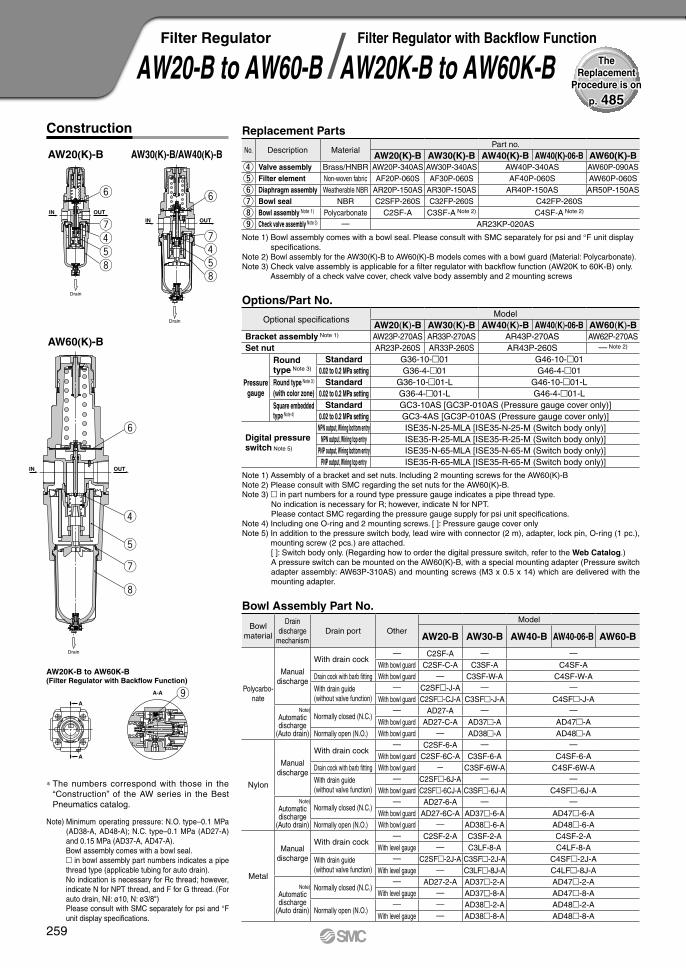
AW20-B to AW60-BFilter Regulator
AW20K-B to AW60K-BFilter Regulator with Backflow Function/
p. 485
TheReplacement
Procedure is on
Options/Part No.
Optional specificationsModel
AW20(K)-B AW30(K)-B AW40(K)-B AW40(K)-06-B AW60(K)-BBracket assembly Note 1) AW23P-270AS AR33P-270AS AR43P-270AS AW62P-270ASSet nut AR23P-260S AR33P-260S AR43P-260S — Note 2)
Pressure gauge
Round type Note 3)
Standard G36-10-01 G46-10-010.02 to 0.2 MPa setting G36-4-01 G46-4-01
Round type Note 3 )
(with color zone)Standard G36-10-01-L G46-10-01-L
0.02 to 0.2 MPa setting G36-4-01-L G46-4-01-LSquare embedded type Note 4)
Standard GC3-10AS [GC3P-010AS (Pressure gauge cover only)]0.02 to 0.2 MPa setting GC3-4AS [GC3P-010AS (Pressure gauge cover only)]
Digital pressure switch Note 5)
NPN output, Wiring bottom entry ISE35-N-25-MLA [ISE35-N-25-M (Switch body only)]NPN output, Wiring top entry ISE35-R-25-MLA [ISE35-R-25-M (Switch body only)]
PNP output, Wiring bottom entry ISE35-N-65-MLA [ISE35-N-65-M (Switch body only)]PNP output, Wiring top entry ISE35-R-65-MLA [ISE35-R-65-M (Switch body only)]
Note 1) Assembly of a bracket and set nuts. Including 2 mounting screws for the AW60(K)-BNote 2) Please consult with SMC regarding the set nuts for the AW60(K)-B.Note 3) in part numbers for a round type pressure gauge indicates a pipe thread type.
No indication is necessary for R; however, indicate N for NPT.Please contact SMC regarding the pressure gauge supply for psi unit specifications.
Note 4) Including one O-ring and 2 mounting screws. [ ]: Pressure gauge cover onlyNote 5) In addition to the pressure switch body, lead wire with connector (2 m), adapter, lock pin, O-ring (1 pc.),
mounting screw (2 pcs.) are attached.[ ]: Switch body only. (Regarding how to order the digital pressure switch, refer to the Web Catalog.)A pressure switch can be mounted on the AW60(K)-B, with a special mounting adapter (Pressure switch adapter assembly: AW63P-310AS) and mounting screws (M3 x 0.5 x 14) which are delivered with the mounting adapter.
Bowl Assembly Part No.
Bowl material
Draindischarge
mechanismDrain port Other
Model
AW20-B AW30-B AW40-B AW40-06-B AW60-B
Polycarbo-nate
Manual discharge
With drain cock— C2SF-A — —
With bowl guard C2SF-C-A C3SF-A C4SF-ADrain cock with barb fitting With bowl guard — C3SF-W-A C4SF-W-A
With drain guide(without valve function)
— C2SF-J-A — —
With bowl guard C2SF-CJ-A C3SF-J-A C4SF-J-ANote)
Automatic discharge
(Auto drain)
Normally closed (N.C.)— AD27-A — —
With bowl guard AD27-C-A AD37-A AD47-ANormally open (N.O.) With bowl guard — AD38-A AD48-A
Nylon
Manual discharge
With drain cock— C2SF-6-A — —
With bowl guard C2SF-6C-A C3SF-6-A C4SF-6-ADrain cock with barb fitting With bowl guard — C3SF-6W-A C4SF-6W-A
With drain guide(without valve function)
— C2SF-6J-A — —
With bowl guard C2SF-6CJ-A C3SF-6J-A C4SF-6J-ANote)
Automatic discharge
(Auto drain)
Normally closed (N.C.)— AD27-6-A — —
With bowl guard AD27-6C-A AD37-6-A AD47-6-ANormally open (N.O.) With bowl guard — AD38-6-A AD48-6-A
Metal
Manual discharge
With drain cock— C2SF-2-A C3SF-2-A C4SF-2-A
With level gauge — C3LF-8-A C4LF-8-A
With drain guide(without valve function)
— C2SF-2J-A C3SF-2J-A C4SF-2J-AWith level gauge — C3LF-8J-A C4LF-8J-A
Note)Automatic discharge
(Auto drain)
Normally closed (N.C.)— AD27-2-A AD37-2-A AD47-2-A
With level gauge — AD37-8-A AD47-8-A
Normally open (N.O.)— — AD38-2-A AD48-2-A
With level gauge — AD38-8-A AD48-8-A
Note) Minimum operating pressure: N.O. type–0.1 MPa (AD38-A, AD48-A); N.C. type–0.1 MPa (AD27-A) and 0.15 MPa (AD37-A, AD47-A).Bowl assembly comes with a bowl seal. in bowl assembly part numbers indicates a pipe thread type (applicable tubing for auto drain).No indication is necessary for Rc thread; however, indicate N for NPT thread, and F for G thread. (For auto drain, Nil: ø10, N: ø3/8")Please consult with SMC separately for psi and °F unit display specifications.
Replacement Parts
No. Description MaterialPart no.
AW20(K)-B AW30(K)-B AW40(K)-B AW40(K)-06-B AW60(K)-Br Valve assembly Brass/HNBR AW20P-340AS AW30P-340AS AW40P-340AS AW60P-090AS
t Filter element Non-woven fabric AF20P-060S AF30P-060S AF40P-060S AW60P-060S
y Diaphragm assembly Weatherable NBR AR20P-150AS AR30P-150AS AR40P-150AS AR50P-150AS
u Bowl seal NBR C2SFP-260S C32FP-260S C42FP-260S
i Bowl assembly Note 1) Polycarbonate C2SF-A C3SF-A Note 2) C4SF-A Note 2)
o Check valve assembly Note 3) — AR23KP-020AS
Note 1) Bowl assembly comes with a bowl seal. Please consult with SMC separately for psi and °F unit display specifications.
Note 2) Bowl assembly for the AW30(K)-B to AW60(K)-B models comes with a bowl guard (Material: Polycarbonate).Note 3) Check valve assembly is applicable for a filter regulator with backflow function (AW20K to 60K-B) only.
Assembly of a check valve cover, check valve body assembly and 2 mounting screws
Construction
AW60(K)-B
AW20(K)-B
AW20K-B to AW60K-B(Filter Regulator with Backflow Function)
AW30(K)-B/AW40(K)-B
* The numbers correspond with those in the “Construction” of the AW series in the Best Pneumatics catalog.
259

AWM20AWD20
t
e
y
r
u
IN OUT
Drain
t
e
y
r
u
IN OUT
Drain
AWM30/40AWD30/40
————————————————
——————————————————
Construction
∗ The numbers correspond with those in the “Construction” of the AW series in the Best Pneumatics catalog.
No. Description
Valve assembly
Element assembly
Diaphragm assemblyBowl O-ringBowl assembly Note 1)
Material
Brass, HNBR——
Weather resistant NBRNBR
Polycarbonate
Part no.
AWM20AWD20
AWM30AWD30
AWM40AWD40
AWM20P-090ASAFM20P-060ASAFD20P-060ASAR20P-150ASC2SFP-260S
C2SF
AWM30P-090ASAFM30P-060ASAFD30P-060ASAR30P-150ASC3SFP-260SC3SF Note 2)
AWM40P-090ASAFM40P-060ASAFD40P-060ASAR40P-150ASC4SFP-260SC4SF Note 2)
e
r
t
y
u
Replacement Parts
Note 1) Bowl O-ring is included. Please contact SMC regarding the bowl assembly supply for psi and °F unit specifications.
Note 2) Bowl assembly for the AWM30/40, AWD30/40 comes with a bowl guard (steel band material).
AWM20 to AWM40
AWD20 to AWD40
Options/Part No.Model
Optional specifications AWM20AWD20
AWM30AWD30
AW20P-270ASAR20P-260S
AD27—
G36-10-01G36-2-01
G36-10-01-LG36-2-01-L
AR30P-270ASAR30P-260S
GC3-10AS [GC3P-010AS (Pressure gauge cover only)]GC3-2AS [GC3P-010AS (Pressure gauge cover only)]ISE35-N-25-MLA [ISE35-N-25-M (Switch body only)]ISE35-R-25-MLA [ISE35-R-25-M (Switch body only)]ISE35-N-65-MLA [ISE35-N-65-M (Switch body only)]ISE35-R-65-MLA [ISE35-R-65-M (Switch body only)]
AD37AD38
AR40P-270ASAR40P-260SG46-10-02G46-2-02
G46-10-02-LG46-2-02-L
AD47AD48
AWM40AWD40
Semi-standard/Bowl Assembly Part No.
———————————————
———————————————————
———————————————
ModelSemi-standard specifications
AWM30AWD30
AWM20AWD20
C2SF-CAD27-CC2SF-J
—C2SF-CJC2SF-6
C2SF-6CAD27-6
—AD27-6CC2SF-6J
—C2SF-6CJ
C2SF-2AD27-2
—C2SF-2J
————
——
C3SF-JC3SF-W
—C3SF-6
—AD37-6AD38-6
—C3SF-6JC3SF-6W
—C3SF-2AD37-2AD38-2
C3SF-2JC3LF-8AD37-8AD38-8C3LF-8J
——
C4SF-JC4SF-W
—C4SF-6
—AD47-6AD48-6
—C4SF-6JC4SF-6W
—C4SF-2AD47-2AD48-2
C4SF-2JC4LF-8AD47-8AD48-8C4LF-8J
AWM40AWD40
Bracket assembly Note 1)
Set nut
Pressuregauge
Digital pressureswitch Note 4)
Float type auto drain Note 5) Note 6)
Round type Note 2)
Standard0.02 to 0.2 MPa setting
Standard0.02 to 0.2 MPa setting
Standard0.02 to 0.2 MPa settingNPN output /Wiring bottom entryNPN output /Wiring top entryPNP output /Wiring bottom entryPNP output /Wiring top entry
N.C.N.O.
Square embeddedtype Note 3)
Round type Note 2)
(with color zone)
N.C. N.O.
Withbowlguard
Withbarbfitting
Bowl material
Polycarbonate
Nylon
Metal
Metal bowl withlevel gauge
Withdrainguide
Note 6)
Float typeauto drain
Note 5) Note 6)
Note 1) Assembly of a bracket and set nutsNote 2) in part numbers for a round pressure
gauge indicates a type of connection thread. No indication is necessary for R; however, indicate N for NPT. Please contact SMC regarding the connection thread NPT and pressure gauge supply for psi unit specifications.
Note 3) Including one O-ring and 2 mounting screws. [ ]: Pressure gauge cover only
Note 4) Lead wire with connector (2 m), adapter, lock pin, O-ring (1 pc.), mounting screw (2 pcs.) are attached. [ ]: Switch body only. Also, regarding how to order the digital pressure switch, refer to the Best Pneumatics catalog.A separate pressure switch adapter assembly (AW60P-310AS) is required only for AW60(K). For mounting, please use the included mounting screws (M3 x 0.5 x 14).The mounting screw (M3 x 0.5 x 7)
attached to the digital pressure switch assembly will not be required.Note 5) Minimum operating pressure: N.O. type–0.1 MPa; N.C. type–0.1 MPa (AD27) and 0.15 MPa
(AD37/47). Please contact SMC for psi and °F unit specifications.Note 6) Please consult SMC for details on drain piping to fit NPT or G port sizes.Note) • Including O-ring.
• Bowl assembly for the AWM30/40, AWD30/40 comes with a bowl guard (steel band material). (except when the bowl material is metal)
AWM(D)20 to AWM(D)40Mist Separator Regulator/Micro Mist Separator Regulator
p. 497, 503
TheReplacement
Procedure is on
260
Act
uat
ors
Modu
lar F.R
.L.Pre
ssure
Contr
ol Eq
uipme
nt A
ir P
rep
arat
ion
Eq
uip
men
tIn
dust
rial
Filt
ers
Repl
acem
ent
Proc
edur
eA
ctu
ato
rsMo
dular
F.R.L.
Pressu
re Co
ntrol
Equip
ment
Indu
stri
al F
ilter
s

B
B
AA
KCOLtoHSUP
y
r
t
i
u
o
B-BA-A
IN OUT
B-B
!0
o
Construction
ARG20/30/40 ARG20K/30K/40K
No. Description
45678910
ValveDiaphragm assemblyValve guide assemblyPressure gauge coverPressure gauge Note 1)
ClipCheck valve assembly Note 2)
Material
Brass, HNBRWeather resistant NBR
POM, NBRPC—
Stainless steel—
Qty.
1111111
Part no.
ARG20(K)AR20P-410S
AR20P-150ASAR20P-050ASARG20P-400S
GB2-10ASARG20P-420S
AR20KP-020AS ARG20K, 30K, 40K
ARG30(K)AR30P-410S
AR30P-150ASAR30P-050ASARG30P-400S
GB3-10ASARG30P-420S
ARG40(K)AR40P-410S
AR40P-150ASAR40P-050ASARG40P-400S
GB4-10ASARG40P-420S
Replacement Parts
Note
∗ The numbers correspond with those in the “Construction” of the ARG series in the Best Pneumatics catalog.
Note 1) Only the standard part numbers are listed for the pressure gauges.Note 2) Check valve assembly contains check valve, check valve cover and its screws (2 pcs).
OptionBracket assembly Note 1)
Set nut
Applicable modelARG40(K)ARG30(K)ARG20(K)
0 to 1.0 MPa0 to 0.3 MPa0 to 150 psi0 to 45 psi
Pressuregaugedisplayrange
Optional
Standard
ARG20P-270ASARG20P-260S
GB2-10ASGB2-3AS
GB2-P10ASGB2-P3AS
ARG30P-270ASARG30P-260S
GB3-10ASGB3-3AS
GB3-P10ASGB3-P3AS
ARG40P-270ASARG40P-260S
GB4-10ASGB4-3AS
GB4-P10ASGB4-P3AS
Options/Part No.
Note 1) Assembly includes a bracket and set nuts.
Pressuregauge
ARG20(K) /30(K) /40(K)Regulator with Built-in Pressure Gauge
p. 509
TheReplacement
Procedure is on
261
D
D
CC KCOLtoHSU
P
B
B
AAKCOLtoHSUP
D-DC-CB-BA-A
!0
o
y
q
u
r
t
i
!1
!0
o
y
u
r
t
i
!1
IN OUT IN OUT
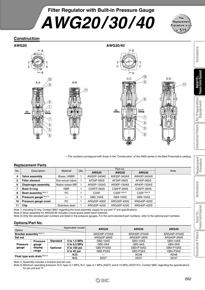
Construction
AWG20 AWG30/40
Note 1) Including O-ring. Contact SMC regarding the bowl assembly supply for psi and °F unit specifications.Note 2) Bowl assembly for AWG30/40 includes a bowl guard (steel band material).Note 3) Only the standard part numbers are listed in the pressure gauges. For the semi-standard part numbers, refer to the optional part numbers.
Note 1) Assembly includes a bracket and set nuts.Note 2) Minimum operating pressure: N.O. type–0.1 MPa; N.C. type–0.1 MPa (AD27) and 0.15 MPa (AD37/47). Contact SMC regarding the specifications
for psi unit and °F.
OptionBracket assembly Note 1)
Set nut
Float type auto drain Note 2)
Applicable model AWG40AWG30AWG20
0 to 1.0 MPa0 to 0.3 MPa0 to 150 psi0 to 45 psi
Pressuregaugedisplayrange
Optional
Standard
ARG20P-270ASARG20P-260S
GB2-10ASGB2-3AS
GB2-P10ASGB2-P3AS
—AD27
ARG30P-270ASARG30P-260S
GB3-10ASGB3-3AS
GB3-P10ASGB3-P3AS
AD38AD37
ARG40P-270ASARG40P-260S
GB4-10ASGB4-3AS
GB4-P10ASGB4-P3AS
AD48AD47
Options/Part No.
Pressuregauge
AW20P-340AS
AF20P-060S
AR20P-150AS
C2SFP-260S
C2SF
GB2-10AS
ARG20P-400S
ARG20P-420S
∗ The numbers correspond with those in the “Construction” of the AWG series in the Best Pneumatics catalog.
Replacement Parts
Description Material Qty. NotePart no.
No.
Brass, HNBR
Non-woven fabric
Weather resistant NBR
NBR
PC
—
PC
Stainless steel
1
1
1
1
1
1
1
1
Valve assembly
Filter element
Diaphragm assembly
Bowl O-ring
Bowl assembly Note 1)
Pressure gauge Note 3)
Pressure gauge cover
Clip
4
5
6
7
8
9
10
11
AW30P-340AS
AF30P-060S
AR30P-150AS
C3SFP-260S
C3SF Note 2)
GB3-10AS
ARG30P-400S
ARG30P-420S
AW40P-340AS
AF40P-060S
AR40P-150AS
C4SFP-260S
C4SF Note 2)
GB4-10AS
ARG40P-400S
ARG40P-420S
AWG20 AWG30 AWG40
N.O.N.C.
AWG20/30 /40Filter Regulator with Built-in Pressure Gauge
p. 515
TheReplacement
Procedure is on
262
Act
uat
ors
Modu
lar F.R
.L.Pre
ssure
Contr
ol Eq
uipme
nt A
ir P
rep
arat
ion
Eq
uip
men
tIn
dust
rial
Filt
ers
Repl
acem
ent
Proc
edur
eA
ctu
ato
rsMo
dular
F.R.L.
Pressu
re Co
ntrol
Equip
ment
Indu
stri
al F
ilter
s

D
D
CC KCOLtoHSUP
B
B
AA KCOLtoHSUP
D-DC-C
A-A B-B!0o
y
urti
!1
!2
!0o
y
!1
!2
urti
IN OUTIN OUT
Construction
AWG20K AWG30K/40K
Note 1) Including O-ring. Contact SMC regarding the bowl assembly supply for psi and °F unit specifications.Note 2) Bowl assembly (AWG30K/40K) includes a bowl guard (steel band material).Note 3) Only the standard part numbers are listed for the pressure gauges. For the semi-standard part numbers, refer to the optional part numbers.
Note 1) Assembly includes a bracket and set nuts.Note 2) Minimum operating pressure: N.O. type–0.1 MPa; N.C. type–0.1 MPa (AD27) and 0.15 MPa (AD37/47). Contact SMC regarding the specifications
for psi unit and °F.
AWG40KAWG30KAWG20K
ARG20P-270ASARG20P-260S
GB2-10ASGB2-3AS
GB2-P10ASGB2-P3AS
—AD27
ARG30P-270ASARG30P-260S
GB3-10ASGB3-3AS
GB3-P10ASGB3-P3AS
AD38AD37
ARG40P-270ASARG40P-260S
GB4-10ASGB4-3AS
GB4-P10ASGB4-P3AS
AD48AD47
Options/Part No.
AW20P-340AS
AF20P-060S
AR20P-150AS
C2SFP-260S
C2SF
GB2-10AS
ARG20P-400S
ARG20P-420S
∗ The numbers correspond with those in the “Construction” of the AWG series in the Best Pneumatics catalog.
Replacement Parts
Description Material Qty. NotePart no.
No.
Brass, HNBR
Non-woven fabric
Weather resistant NBR
NBR
PC
—
PC
Stainless steel
—
1
1
1
1
1
1
1
1
1
Valve assembly
Filter element
Diaphragm assembly
Bowl O-ring
Bowl assembly Note 1)
Pressure gauge Note 3)
Pressure gauge cover
Clip
Check valve assembly
4
5
6
7
8
9
10
11
12
AW30P-340AS
AF30P-060S
AR30P-150AS
C3SFP-260S
C3SF Note2)
GB3-10AS
ARG30P-400S
ARG30P-420S
AR20KP-020AS
AW40P-340AS
AF40P-060S
AR40P-150AS
C4SFP-260S
C4SF Note2)
GB4-10AS
ARG40P-400S
ARG40P-420S
AWG20K AWG30K AWG40K
OptionBracket assembly Note 1)
Set nut
Float type auto drain Note 2)
Applicable model
0 to 1.0 MPa0 to 0.3 MPa0 to 150 psi0 to 45 psi
Pressuregaugedisplayrange
Optional
StandardPressuregauge
N.O.N.C.
AWG20K/30K/40KFilter Regulator with Built-in Pressure Gauge with Backflow Function
263

Construction
Note 1) Diaphragm is included.
Note 1) • In the gauge part no. (e.g. G46-10- 02), indicate kind of the connecting thread. Put nothing for Rc and “N” for NPT thread.• Please consult with SMC for NPT pressure gauge.
Note 2) Use caution not to tighten excessively when mounting a pressure gauge, otherwise it may result in a breakdown. Use a pipe tape for sealing.Recommended torque: 12 to 14 N·m.
132586A
132581A
132572A
135053(AR425)
135025(AR435)
135211
∗ The numbers correspond with those in the “Construction” of the AR series in the Best Pneumatics catalog.
Replacement Parts
Description Material Qty. NotePart no.
No.
—
—
—
Steel wire
Stainless steel
ABS
1
1
1
1
1
1
Exhaust valve assembly Note 1)
Main valve side diaphragm assembly
Valve assembly
Adjusting spring
Valve spring
Knob
5, 11
6
7
8
9
10
132586A
132659A
132653A
135053(AR625)
135025(AR635)
132656
13414
132586A
13275A
132752A
135053(AR825)
135025(AR835)
132713
132586A
13285A
132829A
135053(AR925)
135025(AR935)
13289
AR425/435 AR625/635 AR825/835 AR925/935
o
i
!1
!0
y
t
u
Bleed port
Knob locking screw
Relief port
OUTIN
Options/Part No.Part no.
AR4 5 AR6 5 AR8 5 AR9 5Description Model
Bracket
Pressure gauge with limit indicator Note 1)
B24P B25P
G46-10- 02 (Max. 1.0 MPa), G46-2- 02 (Max. 0.2 MPa)
AR425 to 935Pilot Operated Regulator
p. 522
TheReplacement
Procedure is on
264
Act
uat
ors
Modu
lar F.R
.L.Pre
ssure
Contr
ol Eq
uipme
nt A
ir P
rep
arat
ion
Eq
uip
men
tIn
dust
rial
Filt
ers
Repl
acem
ent
Proc
edur
eA
ctu
ato
rsMo
dular
F.R.L.
Pressu
re Co
ntrol
Equip
ment
Indu
stri
al F
ilter
s

Construction
Note) The MC cartridge element and the separation element are integrated.
13573A
1349161A
13579
135711A
135011
KA00064
135714
1349167
∗ The numbers correspond with those in the “Construction” of the AMR series in the Best Pneumatics catalog.
Replacement Parts
Description Material Qty NotePart no.
No.
Aluminum die-casted
Weather resistant NBR
—
Brass, HNBR
Stainless steel
NBR
Fiber
POM
1
1
1
1
1
1
1
1
Bowl assembly
Diaphragm assembly
Element Note)
Valve assembly
Valve spring
O-ring
Gasket
Knob
4
5
6
7
8
9
10
11
13553A
131515A
135511
13154A
131514
KA00466
635327
131534
13583A
131515A
13589
135811A
131613
KA00452
635327
131534
13563A
131614A
13569
135614-1A
135413
KA00455
63555
131634
AMR3000 AMR4000 AMR5000 AMR6000
Model nameModel AMR3000 AMR4000 AMR5000 AMR6000
Accessory (Standard)/Part No.
Note 5) • in the gauge part number (e.g. G36-10-01) indicates thread. Specify no symbol for “Rc”, and “N” for “NPT”.• Please consult with SMC if “NPT” gauge is required.
Note 6) Use caution not to tighten excessively when mounting a pressure gauge, otherwise it may result in a breakdown. Use a pipe tape for sealing.Recommended tightening torque for pressure regulator: R 1/8 = 7 to 9 N·m, R 1/4 = 12 to 14 N·m
Note 7) Piping adapter, O-ring, Hexagon socket bolt, Hexagon socket bolt assembly. These are shipped together with products. “” in the gauge part number indicates thread type. Specify no symbol for “RC”, “N” for “NPT”, and “G” for “F”.
Note 8) Min. operating pressure = 0.1 MPaNote 9) If a compact pressure switch is mounted later on, an elbow (R x Rc) is necessary.
13576Bracket 13556 13587 13568G36-10-011.0MPaPressure gauge Note 5, 6) G46-10-02
Model nameModel AMR3000 AMR4000 AMR5000 AMR6000
Accessory (Option)/Part No.
AD33-X203 AD33-X202IS10-01 (0.4 MPa setting)
AD33-X210 AD33-X201
135510 135613
Adapter assembly Note 7)
Float type auto drain (AMR100) Note 8)
Compact pressure switchElbow (R x Rc) Note 9)
!1
!0
t
u
i
r
Flow hole A
Drain
MC cartridgeelement
Separationelement
Port size 1/4
OUTIN
Drain
y Auto-drain type
o
AMR3000 to 6000MR Unit (Regulator with Mist Separator)
38
: E3-02 : E3-03
14
34
: E5-04: E5-06
12: E4-02
: E4-03: E4-04
1 43 81 2
: E6-06: E6-10
34
1
p. 526
TheReplacement
Procedure is on
265
X
X
HS
UP
KC
OL
A-A
A A
B
D
C
IN (Centralized supply)
OUT
A
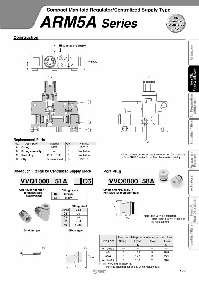
Construction
Replacement PartsDescription Material Part no.No.
NBR
—
PBT, HNBR
Stainless steel
Qty.1
1
1
3
136019
See below
See below
136010
O-ring
Fitting assembly
Port plug
Clip
A
B
C
D
∗ The numbers correspond with those in the “Construction”of the ARM5A series in the Best Pneumatics catalog.
One-touch Fittings for Centralized Supply Block
VVQ1000 51A C6Fitting type
Fitting size
One-touch fittingsfor centralized
supply blockNilL1
StraightElbow
SymbolC6C8N7N9
Sizeø6ø8
ø1/4ø5/16
Straight type Elbow type
T
S
R
U
ø4, ø5/32ø6
ø1/4ø8, ø5/16
Fitting sizeOne-touch fittings for centralized supply block
StraightR—335
ElbowS—
12.512.513.5
ElbowT—191921
ElbowU—
35.535.538.5
Note) The O-ring is attached.Refer to page 528 for details of the replacement.
Port Plug
Single unit regulator/Port plug for regulator block
10
ø10
VVQ0000 58A
Note) The O-ring is attached.Refer to page 527 for details of the replacement.
ARM5A SeriesCompact Manifold Regulator/Centralized Supply Type
p. 527
TheReplacement
Procedure is on
266
Act
uat
ors
Modu
lar F.R
.L.Pre
ssure
Contr
ol Eq
uipme
nt A
ir P
rep
arat
ion
Eq
uip
men
tIn
dust
rial
Filt
ers
Repl
acem
ent
Proc
edur
eA
ctu
ato
rsMo
dular
F.R.L.
Pressu
re Co
ntrol
Equip
ment
Indu
stri
al F
ilter
s

HS
UP
KC
OL
A-A
C
A A
A
OUTIN
B
Single unit regulator/Port plug for regulator block
Construction
Replacement PartsDescription Material Part no.No.
—
PBT, HNBR
Stainless steel
Qty.2
1
3
See below
See below
136010
Fitting assembly
Port plug
Clip
A
B
C
∗ The numbers correspond with those in the “Construction”of the ARM5B series in the Best Pneumatics catalog.
VVQ0000 58A
One-touch Fittings for Regulator Block
VVQ1000 50A C4Fitting type
Fitting size
One-touch fittingsfor regulator block Nil
L1StraightElbow
SymbolC4C6N3N7
Sizeø4ø6
ø5/32ø1/4
Straight type Elbow type
XW
V
Y
ø4, ø5/32ø6
ø1/4ø8, ø5/16
Fitting sizeOne-touch fittings for regulator block
StraightV
2.53 6.5—
ElbowW6 6.56 —
ElbowX
11 11 11.5—
ElbowY
35.536 38.5—
Note) The O-ring is attached.Refer to page 528 for details of the replacement.
Port Plug
10
ø10
Note) The O-ring is attached.Refer to page 527 for details of the replacement.
ARM5B SeriesCompact Manifold Regulator/Individual Supply Type
p. 527
TheReplacement
Procedure is on
267
B
CA
HS
UP
KC
OL
A
OUT
A
IN
A-A
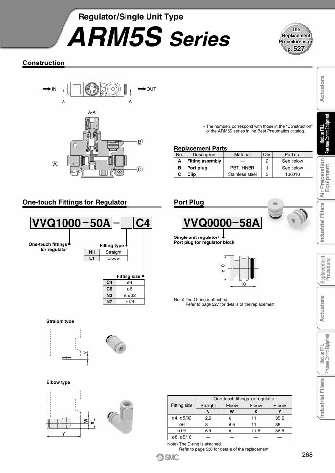
One-touch Fittings for Regulator
VVQ1000 50A C4
Fitting typeOne-touch fittingsfor regulator Straight
ElbowNilL1
Fitting sizeC4C6N3N7
ø4ø6
ø5/32ø1/4
Straight type
V
Elbow type
XW
Y
ø4, ø5/32ø6
ø1/4ø8, ø5/16
Fitting sizeOne-touch fittings for regulator
StraightV
2.53 6.5—
ElbowW6 6.56 —
ElbowX
11 11 11.5—
ElbowY
35.536 38.5—
Note) The O-ring is attached.Refer to page 528 for details of the replacement.
Construction
Replacement PartsDescription Material Part no.No.
—
PBT, HNBR
Stainless steel
Qty.2
1
3
See below
See below
136010
Fitting assembly
Port plug
Clip
A
B
C
∗ The numbers correspond with those in the “Construction” of the ARM5S series in the Best Pneumatics catalog.
Port Plug
Single unit regulator/Port plug for regulator block
10
ø10
VVQ0000 58A
Note) The O-ring is attached.Refer to page 527 for details of the replacement.
ARM5S SeriesRegulator/Single Unit Type
p. 527
TheReplacement
Procedure is on
268
Act
uat
ors
Modu
lar F.R
.L.Pre
ssure
Contr
ol Eq
uipme
nt A
ir P
rep
arat
ion
Eq
uip
men
tIn
dust
rial
Filt
ers
Repl
acem
ent
Proc
edur
eA
ctu
ato
rsMo
dular
F.R.L.
Pressu
re Co
ntrol
Equip
ment
Indu
stri
al F
ilter
s

ARM10 ARM10F
A
E
D
C
F
G
B
F
A
E
D
B
C
G
Construction
Replacement PartsDescription NoteMaterial Part no.No.
Weather resistant
NBR, POM
HNBR,
Aluminum alloy
Stainless steel
NBR
HNBR
NBR
HNBR
NBR
HNBR
NBR
HNBR
—
136126A
136126-1A
136127-30#1
136131
136146
136146-30
136147
136147-30
136148
136148-30
KA01731
KA01613
The right reference
Relieving type
Non-relieving type
Standard model
Oil-free specification
Standard model
Oil-free specification
Standard model
Oil-free specification
Valve
Valve spring
O-ring
O-ring
O-ring
Fitting assembly
A
B
C
D
E
F
G
∗ The numbers correspond with those in the “Construction”of the ARM10 series in the Best Pneumatics catalog.
Diaphragmassembly
Standard model fordigital pressure switch
Oil-free spec. fordigital pressure switch
One-touch Fittings for Regulator
X
VVQ1000-50A C4Fitting typeOne-touch fittings
for regulator SymbolNilL1
TypeStraightElbow
SymbolC4C6N3N7
Sizeø4ø6
ø5/32ø1/4
Fitting size
X10.510.510.5
Y21.522 24.5
Fitting sizeø4, ø5/32
ø6ø1/4
X15.515.515.5
Y21.522 24.5
Fitting sizeø4, ø5/32
ø6ø1/4
X 7 711
Fitting sizeø4, ø5/32
ø6ø1/4
OptionSymbol
NilX17
DescriptionNone
Oil-free
Straight type
Elbow type Elbow type
Y
5.5
X
ARM10Straight type
ARM10F
X10
.5
Y
X
X226
Fitting sizeø4, ø5/32
ø6ø1/4
ARM10 SeriesRegulator/Single Unit Type
p. 531
TheReplacement
Procedure is on
269

A-AA
OUTIN
KCOLHSUP
SMC
SMC
A
K
H
J
G
C
B
E
F
A
D
Construction
Replacement PartsDescription NoteMaterial Part no.No.
Weather resistant NBR, POM
HNBR, Aluminum alloy
Stainless steel
HNBR
NBR
HNBR
NBR
HNBR
NBR
HNBR
NBR
HNBR
NBR
HNBR
—
PBT/HNBR
136126A
136126-1A
136127-30#1
136131
136137-30
136146
136146-30
136147
136147-30
136148
136148-30
KA01731
KA01613
136149
136149-30
Refer to page 272.
Refer to page 272.
Relieving type
Non-relieving type
Standard model
Oil-free specification
Standard model
Oil-free specification
Standard model
Oil-free specification
Standard model for digital pressure switch
Oil-free spec. for digital pressure switch
Standard model
Oil-free specification
Diaphragm assembly
Valve
Valve spring
Gasket
O-ring
O-ring
O-ring
O-ring
Fitting assembly
Port plug
A
B
C
D
E
F
G
H
J
K
∗ The numbers correspond with those in the “Construction” of the ARM11A series in the Best Pneumatics catalog.
ARM11A SeriesCompact Manifold Regulator/Common Supply Type
p. 531
TheReplacement
Procedure is on
270
Act
uat
ors
Modu
lar F.R
.L.Pre
ssure
Contr
ol Eq
uipme
nt A
ir P
rep
arat
ion
Eq
uip
men
tIn
dust
rial
Filt
ers
Repl
acem
ent
Proc
edur
eA
ctu
ato
rsMo
dular
F.R.L.
Pressu
re Co
ntrol
Equip
ment
Indu
stri
al F
ilter
s

A-A
A
A
OUTIN
KCOLHSUP
SMC
SMC
K
H
F
E
B
C
G
A
D
J
Construction
Replacement PartsDescription NoteMaterial Part no.No.
Weather resistant NBR, POM
HNBR, Aluminum alloy
Stainless steel
HNBR
NBR
HNBR
NBR
HNBR
NBR
HNBR
NBR
HNBR
NBR
HNBR
—
PBT/HNBR
136126A
136126-1A
136127-30#1
136131
136137-30
136146
136146-30
136147
136147-30
136148
136148-30
KA01731
KA01613
136149
136149-30
Refer to page 272.
Refer to page 272.
Relieving type
Non-relieving type
Standard model
Oil-free specification
Standard model
Oil-free specification
Standard model
Oil-free specification
Standard model for digital pressure switch
Oil-free spec. for digital pressure switch
Standard model
Oil-free specification
Diaphragm assembly
Valve
Valve spring
Gasket
O-ring
O-ring
O-ring
O-ring
Fitting assembly
Port plug
A
B
C
D
E
F
G
H
J
K
∗ The numbers correspond with those in the “Construction” of the ARM11B series in the Best Pneumatics catalog.
ARM11B SeriesCompact Manifold Regulator/Individual Supply Type
p. 531
TheReplacement
Procedure is on
271

VVQ1000 50A C4One-touchfittings for
regulator block
VVQ2000 51A C6One-touch fittings
for regulatorX
Straight type
X
Straight type
X 12.5
Y
Elbow type
Y
X
Elbow type
6.5
One-touch Fittings for Regulator Block
One-touch Fittings for Common Supply Block
SymbolC4C6N3N7
Sizeø4ø6
ø5/32ø1/4
Fitting size
SymbolC6C8C10N7N9N11
Sizeø6ø8
ø10ø1/4
ø5/16ø3/8
Fitting size
Semi-standardSymbol
NilX17
DescriptionNone
Oil-free
Semi-standardSymbol
NilX17
DescriptionNone
Oil-free
X11.511.511.5
Y19 19.522
Fitting sizeø4, ø5/32
ø6ø1/4
X19202219
Y20 23 26 20.5
Fitting sizeø6
ø8, ø5/16ø10, ø3/8
ø1/4
X337
Fitting sizeø4, ø5/32
ø6ø1/4
X5 5 5.55
Fitting sizeø6
ø8, ø5/16ø10, ø3/8
ø1/4
Fitting typeSymbol
NilL1
TypeStraightElbow
Fitting typeSymbol
NilL1
TypeStraightElbow
VVQ0000 58ASingle unit regulator/Port plug for regulator block
10
ø10
Port Plug
Semi-standardSymbol
NilX17
DescriptionNone
Oil-free
ARM11A/B SeriesCompact Manifold Regulator
Optionsp. 531
TheReplacement
Procedure is on
272
Act
uat
ors
Modu
lar F.R
.L.Pre
ssure
Contr
ol Eq
uipme
nt A
ir P
rep
arat
ion
Eq
uip
men
tIn
dust
rial
Filt
ers
Repl
acem
ent
Proc
edur
eA
ctu
ato
rsMo
dular
F.R.L.
Pressu
re Co
ntrol
Equip
ment
Indu
stri
al F
ilter
s