Embed Size (px)
Citation preview
1
Modular contact-free conveyors for handling planarfragile objects
Valerian Guelpa, Guillaume J. Laurent, Bassem Dahroug and Nadine Le Fort-Piat
Abstract—Recent studies show that the handling of thin wafersin the photovoltaic industry can lead to unacceptable yieldsdue to cell scratching and breaking. This paper presents theconcept and design of a novel modular conveyor, intended forhandling planar fragile objects at high speed without contact.Each element of the conveyor is a square block able to generatetilted air jets that lift and push the object in a single direction.Various handling functions can thus be achieved by the assemblyof several blocks. To manage the complexity of assemblingsystems composed of hundreds of blocks, an automatized designmethodology is proposed. This process gives the best topologyof the conveyor that meets expected specifications (trajectory,speed, travel time, etc.). The optimization relies on the physicalmodel of the modular system describing the motion of the objectpushed by directed air-jets. Experimental comparisons show thatthe simulation predicts accurately the motion of a glass waferaccording to the arrangement of the blocks and the volume of airflow. A maximal speed of 0.3 m/s was experimentally observed,and on larger simulated conveyors, the speed of the wafer couldtheoretically reach 2.9 m/s.
Index Terms—Contactless handling, wafer handling, modulardesign, air film manipulation, distributed manipulation
I. INTRODUCTION
Today, the vast majority of photovoltaic (PV) solar cellsare still based on crystalline silicon wafers. This technologyis expected to remain dominant for at least 10 years [1]. As rawsilicon is expensive and in short supply, the main challengesfor the PV industry are to improve the efficiency and effective-ness of resource consumption through raw materials reduction,improved cell concepts and automation of manufacturing [2].This has led the PV industry to follow the semiconductorindustry in finding ways of making thinner substrates [3].
But recent industrial studies have shown that the use of thinwafers can lead to unacceptable yields arising from wafer andcell breakage due to handling during production [4]. Indeed,as wafer thickness decreases, wafers are less stable and morevulnerable to stresses, and dies can be prone to breaking andscratching especially during handling between machines [5].
Conventional wafer-transfer systems use comb pairs to liftwafers out of carriers and comb assemblies to retain thewafers. The low thickness of the wafers and their sharpedges make it difficult to consistently position the combs,which ultimately can cause wafer breakage [3]. Bernoulli
This work was supported in part by the Smart Blocks project (ANR-251-2011-BS03-005), by the Labex ACTION project (ANR-11-LABX-01-01) andby the Franche-Comte region.
V. Guelpa, G. J. Laurent, B. Dahroug and N. Le Fort-Piat arewith the FEMTO-ST Institute, Univ. Bourgogne Franche-Comte,UFC/ENSMM/CNRS, Besancon, France, corresponding author:[email protected]
grippers are also widely used as non-contact end effectorsfor “gentle handling”. But Bernoulli grippers still need somemeans of holding the wafer so it doesn’t drift around as thegripper moves it. Moreover when handling thin wafers, thelow pressure tends to deform the wafer and can lead to cracksand wafer breakage [4].
Low-cost thin wafer handling has been identified as one ofthe difficult challenges in the 2013 International TechnologyRoadmap For Semiconductors Roadmap [6]. To address thesechallenges new wafer handling technologies have to be devel-oped.
An alternative solution is to levitate the substrate. Forinstance, air bearings are widely used to transport large,thin and heavy products like glass and LCD panels [7], [8].Instead of pressurized air fed through orifices or porous media,ultrasound bearings can also be used to lift a substrate overa vibrating plate [9], [10], [11], [12]. But air bearing andvibrating tables realize only the levitation of product; thelateral motion is still realized by another principle (gravity,wheels, belt conveyors).
To move wafers, a set of inclined holes can create an air flowin addition to the air cushion under the object. Combinationof several nozzles with different orientations can producedifferent functions such as transfer track, position controltrack, orientation control track, etc.
This paper presents a novel concept of a contact-free con-veyor for transporting planar fragile objects like silicon wafers,solar cells, glass and LCD panels, paper sheets, etc. This con-veyor is intended to fulfill various functions such as moving,capturing, guiding, centering, rotating, etc. As opposed to verycomplex devices dedicated to one task and motion, we proposea modular approach based on simple unidirectional blocks thatcan be assembled together to perform the desired function.This concept, covering all the handling functions in a singledesign, allows cost reduction and the making of various andlarge conveyors.
To manage the complexity of assembling such modularsystems, we also propose a general and automatized method-ology that gives the topology of the conveyor according togiven industrial specifications. To this end, we express theblock arrangement problem into an optimization problem. Thisplanning phase is carried offline during the design of theproduction line and before its implementation. This optimaldesign methodology relies on an accurate physical model oftilted air jet levitation and propulsion.
The main contributions of this paper are: (i) the conceptand design of a contact-free modular conveyor, (ii) a completephysical model of the dynamics of the object propelled by
2
air jets, the proposed model being carefully validated withexperiments, (iii) an automatic design methodology able tofind the best topology addressing a given set of specifications.
This paper is organized as follows. The modular conceptis presented in section II. Section III presents the physicalmodeling, its software implementation and its experimentalvalidation. In section IV, we propose a method to automaticallydesign conveyors based on a optimization procedure. SectionV concludes the paper.
II. MODULAR CONVEYOR
This section introduces the modular concept after a shortpresentation of related works. An exhaustive survey on airfilm transportation has been published previously in [13].
A. Air Film Wafer Transportation
The first attempts to use air films to transport and positionwafers were carried out at Texas Instruments Corporation byHagler et al. [14] and at IBM by Hassan and Paivanas [15],[16]. Toda et al. [17], [18] improved the concept and made atransfer system for 300 mm wafer. The wafer track consists ofa perforated plate with 0.5 mm-diameter tilted holes. Transporttimes of less than 15 sec, from wafer moving at 0.12 m.s− 1
to wafer stopping, were achieved in the 0.8 m-long wafertransport track.
Similar systems have been investigated by Moon andHwang [19] and by Kim and Shin [20], [21]. Kim and Shinproposed some methods to compute the precise position on thewafer with cheap photo proximity sensors but no experimentalperformances are reported. Arrays of tilted air-jets have beenused to transport various thin products. For instance, the XeroxPARK handling system [22], [23] uses 1,152 directed air-jetsin a 12 in. × 12 in. array to levitate paper sheets. The systemhas demonstrated closed-loop trajectory tracking with typicalvelocity about 30 mm.s− 1.
In [24], [25], Wesselingh et al. introduced a new concept ofwafer positioning based on an array of cells able to generatean air film for both suspension and motion. Their device isdedicated to wafer micro-positioning. A servo error of 20 µ m(P-P) and a positioning repeatability of 3 µ m (STD) werereported with low cost optical sensors that detect the edge ofthe wafer [26].
Luntz and Moon [27], [28], [29], [30] proposed anotherprinciple based on potential air flow to move an object onan air-hockey table. Their method allows the movement ofan object to a unique final pose using airflow fields withoutsensors. Laurent et al. [31], [32], [33] used a similar tractionprinciple to move a product using an array of vertical air jets toinduce desired potential air flow over the surface. This deviceis able to move centimeter-sized objects up to 0.2 m.s− 1 withmillimeter closed-loop positioning accuracy.
The proposed solutions are often too slow to meet industrialhigh throughput demands. For example, recent PV processingmachines can reach throughput rates of 15 000 wafers per hour,leading to velocities up to 2 m.s − 1 in a serial flux (with twowafers by meter in the line).
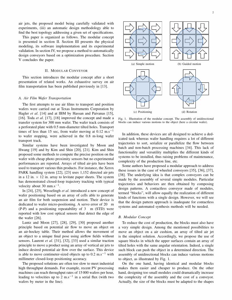
(a) Simple motion (b) Guided motion
(c) Positioning (d) Rotation
Fig. 1. Illustration of the modular concept. The assembly of unidirectionalblocks can induce various motions to the object (here a circular wafer).
In addition, these devices are all designed to achieve a ded-icated task whereas wafer handling requires a lot of differenttrajectories to sort, serialize or parallelize the flow betweenbatch and non-batch processing machines [34]. This lack offunctionality and versatility multiplies the different kinds ofsystems to be installed, thus raising problems of maintenance,complexity of the production line, etc.
Some authors have proposed a modular approach to addressthese issues in the case of wheeled conveyors [35], [36], [37],[38]. The underlying idea is that complex conveyors can bemade by the assembly of several simple modules. Particulartrajectories and behaviors are then obtained by composingdesign patterns. A contactless conveyor made of modules,termed “blocks”, will allow equally the realization of differentkinds of functions with a single design. However, we will seethat the design pattern approach is inadequate for contactlesssystems and automated synthesis methods will be needed.
B. Modular Concept
To reduce the cost of production, the blocks must also havea very simple design. Among the mentioned possibilities tomove an object on a air cushion, an array of tilted air jetis the simplest solution. Accordingly, we propose the use ofsquare blocks in which the upper surfaces contain an array oftilted holes with the same angular orientation. Indeed, a singlesuch block can push the object in a determined direction. Theassembly of unidirectional blocks can induce various motionsto object, as illustrated by Fig. 1.
On the one hand, having identical and modular blocksmakes them easier and cheaper to produce. On the otherhand, designing too small modules could dramatically increasethe complexity of the assembly and the cost of a conveyor.Actually, the size of the blocks must be adapted to the shapes
3
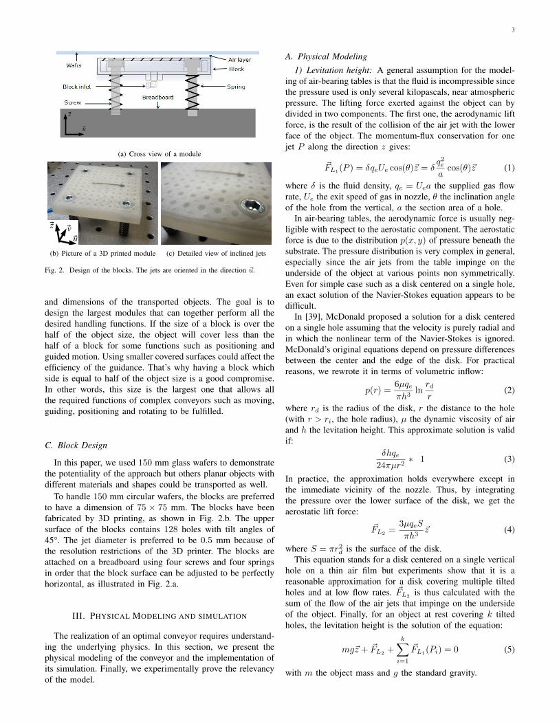
u
z
(a) Cross view of a module
uvz
(b) Picture of a 3D printed module (c) Detailed view of inclined jets
Fig. 2. Design of the blocks. The jets are oriented in the direction ~u.
and dimensions of the transported objects. The goal is todesign the largest modules that can together perform all thedesired handling functions. If the size of a block is over thehalf of the object size, the object will cover less than thehalf of a block for some functions such as positioning andguided motion. Using smaller covered surfaces could affect theefficiency of the guidance. That’s why having a block whichside is equal to half of the object size is a good compromise.In other words, this size is the largest one that allows allthe required functions of complex conveyors such as moving,guiding, positioning and rotating to be fulfilled.
C. Block Design
In this paper, we used 150 mm glass wafers to demonstratethe potentiality of the approach but others planar objects withdifferent materials and shapes could be transported as well.
To handle 150 mm circular wafers, the blocks are preferredto have a dimension of 75 75 mm. The blocks have beenfabricated by 3D printing, as shown in Fig. 2.b. The uppersurface of the blocks contains 128 holes with tilt angles of45°. The jet diameter is preferred to be 0:5 mm because ofthe resolution restrictions of the 3D printer. The blocks areattached on a breadboard using four screws and four springsin order that the block surface can be adjusted to be perfectlyhorizontal, as illustrated in Fig. 2.a.
III. PHYSICAL MODELING AND SIMULATION
The realization of an optimal conveyor requires understand-ing the underlying physics. In this section, we present thephysical modeling of the conveyor and the implementation ofits simulation. Finally, we experimentally prove the relevancyof the model.
A. Physical Modeling
1) Levitation height: A general assumption for the model-ing of air-bearing tables is that the fluid is incompressible sincethe pressure used is only several kilopascals, near atmosphericpressure. The lifting force exerted against the object can bydivided in two components. The first one, the aerodynamic liftforce, is the result of the collision of the air jet with the lowerface of the object. The momentum-flux conservation for onejet P along the direction z gives:
~FL1(P ) = δqeUe cos()~z = δ
q2ea
cos()~z (1)
where δ is the fluid density, qe = Uea the supplied gas flowrate, Ue the exit speed of gas in nozzle, the inclination angleof the hole from the vertical, a the section area of a hole.
In air-bearing tables, the aerodynamic force is usually neg-ligible with respect to the aerostatic component. The aerostaticforce is due to the distribution p(x; y) of pressure beneath thesubstrate. The pressure distribution is very complex in general,especially since the air jets from the table impinge on theunderside of the object at various points non symmetrically.Even for simple case such as a disk centered on a single hole,an exact solution of the Navier-Stokes equation appears to bedifficult.
In [39], McDonald proposed a solution for a disk centeredon a single hole assuming that the velocity is purely radial andin which the nonlinear term of the Navier-Stokes is ignored.McDonald’s original equations depend on pressure differencesbetween the center and the edge of the disk. For practicalreasons, we rewrote it in terms of volumetric inflow:
p(r) =6qeh3
lnrdr
(2)
where rd is the radius of the disk, r the distance to the hole(with r > ri, the hole radius), the dynamic viscosity of airand h the levitation height. This approximate solution is validif:
δhqe24r2
∗ 1 (3)
In practice, the approximation holds everywhere except inthe immediate vicinity of the nozzle. Thus, by integratingthe pressure over the lower surface of the disk, we get theaerostatic lift force:
~FL2=
3qeS
h3~z (4)
where S = r2d is the surface of the disk.This equation stands for a disk centered on a single vertical
hole on a thin air film but experiments show that it is areasonable approximation for a disk covering multiple tiltedholes and at low flow rates. ~FL2
is thus calculated with thesum of the flow of the air jets that impinge on the undersideof the object. Finally, for an object at rest covering k tiltedholes, the levitation height is the solution of the equation:
mg~z + ~FL2 +kXi=1
~FL1(Pi) = 0 (5)
with m the object mass and g the standard gravity.
4
Wafer
Block
V (G)
Ue ,qe
h
a
F P (Pi)
u
z
u
v
Block Wafer
V (G)
V (Pi)
UeU eU eU e
F P (Pi)
UeU eU eU e
Ω(G)
F L1(Pi)
F D1+F D2
F L2
F D 2
F D1
Θ
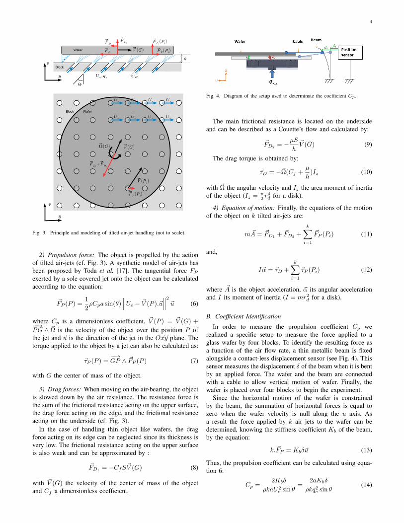
Fig. 3. Principle and modeling of tilted air-jet handling (not to scale).
2) Propulsion force: The object is propelled by the actionof tilted air-jets (cf. Fig. 3). A synthetic model of air-jets hasbeen proposed by Toda et al. [17]. The tangential force FPexerted by a sole covered jet onto the object can be calculatedaccording to the equation:
FP (P ) =1
2ρCpa sin(θ)
∥∥∥Ue − V (P ).u∥∥∥2 u (6)
where Cp is a dimensionless coefficient, V (P ) = V (G) +−−→PG∧Ω is the velocity of the object over the position P ofthe jet and u is the direction of the jet in the Oxy plane. Thetorque applied to the object by a jet can also be calculated as:
τP (P ) =−−→GP ∧FP (P ) (7)
with G the center of mass of the object.
3) Drag forces: When moving on the air-bearing, the objectis slowed down by the air resistance. The resistance force isthe sum of the frictional resistance acting on the upper surface,the drag force acting on the edge, and the frictional resistanceacting on the underside (cf. Fig. 3).
In the case of handling thin object like wafers, the dragforce acting on its edge can be neglected since its thickness isvery low. The frictional resistance acting on the upper surfaceis also weak and can be approximated by :
FD1= −CfSV (G) (8)
with V (G) the velocity of the center of mass of the objectand Cf a dimensionless coefficient.
Fig. 4. Diagram of the setup used to determinate the coefficient Cp.
The main frictional resistance is located on the undersideand can be described as a Couette’s flow and calculated by:
FD2= − µ S
hV (G) (9)
The drag torque is obtained by:
τD = −Ω(Cf +µ
h)Iz (10)
with Ω the angular velocity and Iz the area moment of inertiaof the object (Iz = π
2 r4d for a disk).
4) Equation of motion: Finally, the equations of the motionof the object on k tilted air-jets are:
mA = FD1+ FD2
+
k∑i=1
FP (Pi) (11)
and,
Iα = τD +
k∑i=1
τP (Pi) (12)
where A is the object acceleration, α its angular accelerationand I its moment of inertia (I = mr2d for a disk).
B. Coefficient Identification
In order to measure the propulsion coefficient Cp werealized a specific setup to measure the force applied to aglass wafer by four blocks. To identify the resulting force asa function of the air flow rate, a thin metallic beam is fixedalongside a contact-less displacement sensor (see Fig. 4). Thissensor measures the displacement δ of the beam when it is bentby an applied force. The wafer and the beam are connectedwith a cable to allow vertical motion of wafer. Finally, thewafer is placed over four blocks to begin the experiment.
Since the horizontal motion of the wafer is constrainedby the beam, the summation of horizontal forces is equal tozero when the wafer velocity is null along the u axis. Asa result the force applied by k air jets to the wafer can bedetermined, knowing the stiffness coefficient Kb of the beam,by the equation:
k.FP = Kbδu (13)
Thus, the propulsion coefficient can be calculated using equa-tion 6:
Cp =2Kbδ
ρkaU2e sin θ
=2aKbδ
ρkq2e sin θ(14)
5
0 5 10 15 20 25 30 350
0.005
0.01
0.015
Mass flow rate (Ls/min)
Fo
rce (
N)
Model
mass1=11.69g
mass2=13.77g
mass3=20.38g
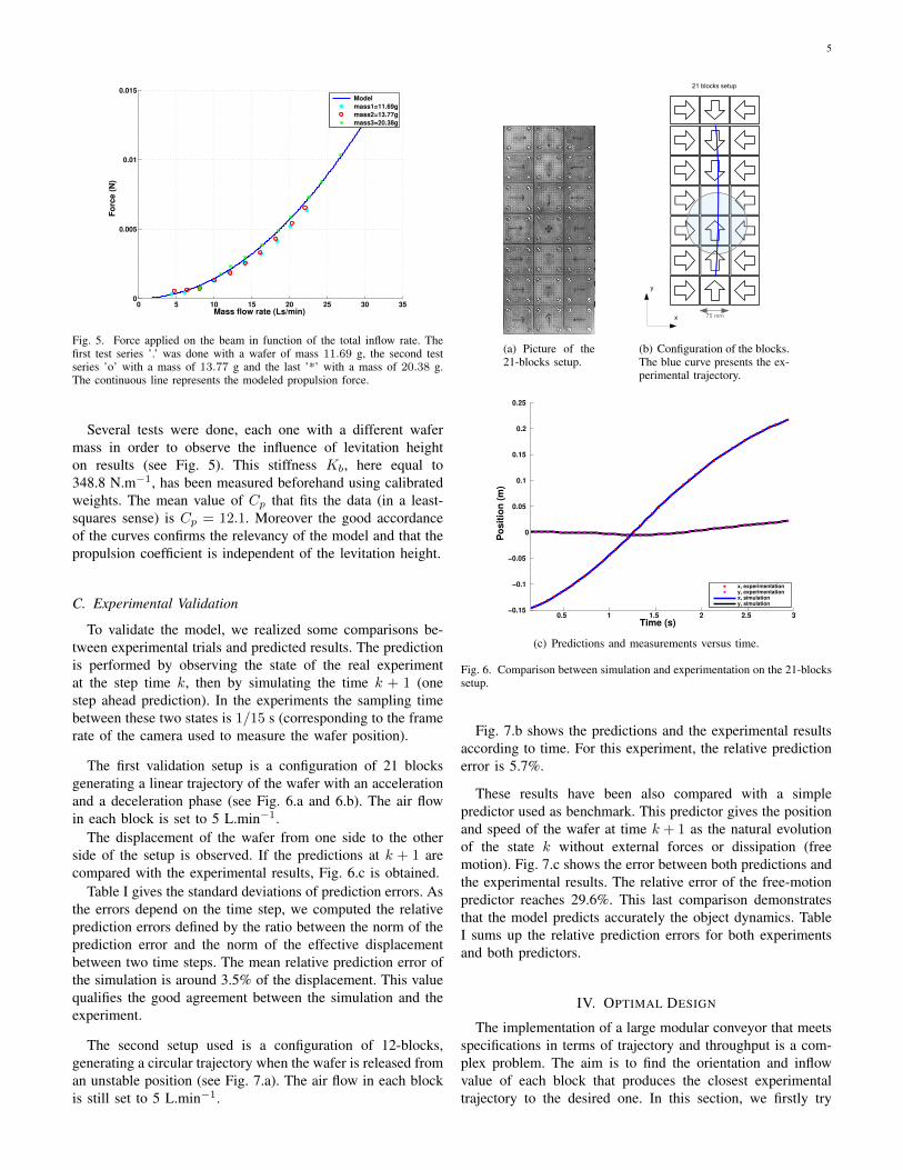
Fig. 5. Force applied on the beam in function of the total inflow rate. Thefirst test series ’.’ was done with a wafer of mass 11. 69 g, the second testseries ’o’ with a mass of 13. 77 g and the last ’*’ with a mass of 20. 38 g.The continuous line represents the modeled propulsion force.
Several tests were done, each one with a different wafermass in order to observe the influence of levitation heighton results (see Fig. 5). This stiffness Kb, here equal to348.8 N.m− 1, has been measured beforehand using calibratedweights. The mean value of Cp that fits the data (in a least-squares sense) is Cp = 12.1. Moreover the good accordanceof the curves confirms the relevancy of the model and that thepropulsion coefficient is independent of the levitation height.
C. Experimental Validation
To validate the model, we realized some comparisons be-tween experimental trials and predicted results. The predictionis performed by observing the state of the real experimentat the step time k, then by simulating the time k + 1 (onestep ahead prediction). In the experiments the sampling timebetween these two states is 1/15 s (corresponding to the framerate of the camera used to measure the wafer position).
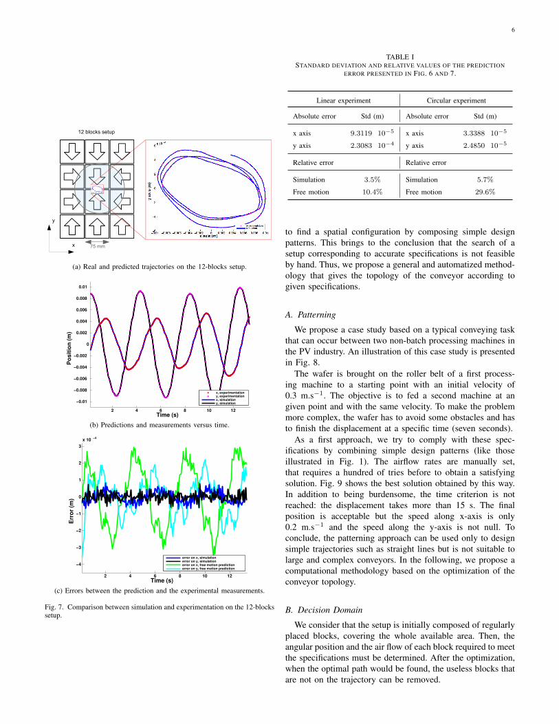
The first validation setup is a configuration of 21 blocksgenerating a linear trajectory of the wafer with an accelerationand a deceleration phase (see Fig. 6.a and 6.b). The air flowin each block is set to 5 L.min− 1.
The displacement of the wafer from one side to the otherside of the setup is observed. If the predictions at k + 1 arecompared with the experimental results, Fig. 6.c is obtained.
Table I gives the standard deviations of prediction errors. Asthe errors depend on the time step, we computed the relativeprediction errors defined by the ratio between the norm of theprediction error and the norm of the effective displacementbetween two time steps. The mean relative prediction error ofthe simulation is around 3.5% of the displacement. This valuequalifies the good agreement between the simulation and theexperiment.
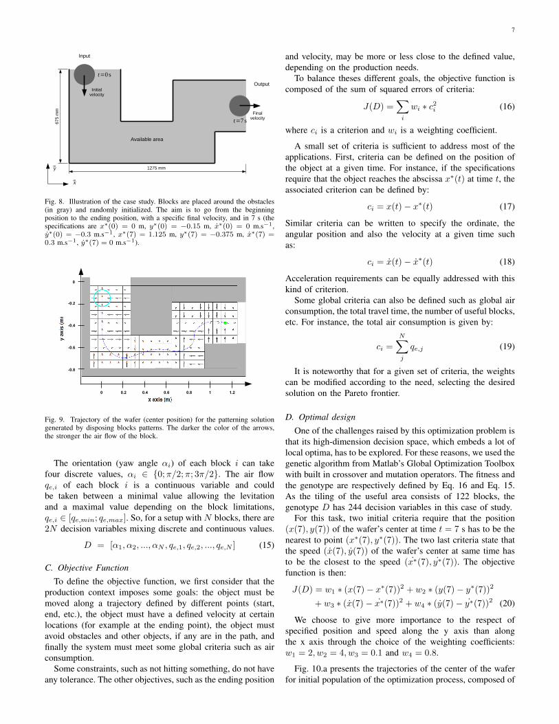
The second setup used is a configuration of 12-blocks,generating a circular trajectory when the wafer is released froman unstable position (see Fig. 7.a). The air flow in each blockis still set to 5 L.min − 1.
(a) Picture of the21-blocks setup.
y
x
21 blocks setup
75 mm
(b) Configuration of the blocks.The blue curve presents the ex-perimental trajectory.
0.5 1 1.5 2 2.5 3−0.15
−0.1
−0.05
0
0.05
0.1
0.15
0.2
0.25
Po
sit
ion
(m
)
Time (s)
x, experimentationy, experimentationx, simulationy, simulation
(c) Predictions and measurements versus time.
Fig. 6. Comparison between simulation and experimentation on the 21-blockssetup.
Fig. 7.b shows the predictions and the experimental resultsaccording to time. For this experiment, the relative predictionerror is 5.7%.
These results have been also compared with a simplepredictor used as benchmark. This predictor gives the positionand speed of the wafer at time k + 1 as the natural evolutionof the state k without external forces or dissipation (freemotion). Fig. 7.c shows the error between both predictions andthe experimental results. The relative error of the free-motionpredictor reaches 29.6%. This last comparison demonstratesthat the model predicts accurately the object dynamics. TableI sums up the relative prediction errors for both experimentsand both predictors.
IV. OPTIMAL DESIGN
The implementation of a large modular conveyor that meetsspecifications in terms of trajectory and throughput is a com-plex problem. The aim is to find the orientation and inflowvalue of each block that produces the closest experimentaltrajectory to the desired one. In this section, we firstly try
6
y
x
12 blocks setup
75 mm
(a) Real and predicted trajectories on the 12-blocks setup.
2 4 6 8 10 12
−0.01
−0.008
−0.006
−0.004
−0.002
0
0.002
0.004
0.006
0.008
0.01
Po
sit
ion
(m
)
Time (s)
x, experimentationy, experimentationx, simulationy, simulation
(b) Predictions and measurements versus time.
2 4 6 8 10 12
−4
−3
−2
−1
0
1
2
3
x 10−4
Err
or
(m)
Time (s)
error on x, simulationerror on y, simulationerror on x, free motion predictionerror on y, free motion prediction
(c) Errors between the prediction and the experimental measurements.
Fig. 7. Comparison between simulation and experimentation on the 12-blockssetup.
TABLE ISTANDARD DEVIATION AND RELATIVE VALUES OF THE PREDICTION
ERROR PRESENTED IN FIG. 6 AND 7.
Linear experiment Circular experiment
Absolute error Std (m) Absolute error Std (m)
x axis 9. 3119 · 10 − 5 x axis 3. 3388 · 10 − 5
y axis 2. 3083 · 10 − 4 y axis 2. 4850 · 10 − 5
Relative error Relative error
Simulation 3. 5% Simulation 5. 7%
Free motion 10. 4% Free motion 29. 6%
to find a spatial configuration by composing simple designpatterns. This brings to the conclusion that the search of asetup corresponding to accurate specifications is not feasibleby hand. Thus, we propose a general and automatized method-ology that gives the topology of the conveyor according togiven specifications.
A. Patterning
We propose a case study based on a typical conveying taskthat can occur between two non-batch processing machines inthe PV industry. An illustration of this case study is presentedin Fig. 8.
The wafer is brought on the roller belt of a first process-ing machine to a starting point with an initial velocity of0.3 m.s − 1. The objective is to fed a second machine at angiven point and with the same velocity. To make the problemmore complex, the wafer has to avoid some obstacles and hasto finish the displacement at a specific time (seven seconds).
As a first approach, we try to comply with these spec-ifications by combining simple design patterns (like thoseillustrated in Fig. 1). The airflow rates are manually set,that requires a hundred of tries before to obtain a satisfyingsolution. Fig. 9 shows the best solution obtained by this way.In addition to being burdensome, the time criterion is notreached: the displacement takes more than 15 s. The finalposition is acceptable but the speed along x-axis is only0.2 m.s− 1 and the speed along the y-axis is not null. Toconclude, the patterning approach can be used only to designsimple trajectories such as straight lines but is not suitable tolarge and complex conveyors. In the following, we propose acomputational methodology based on the optimization of theconveyor topology.
B. Decision Domain
We consider that the setup is initially composed of regularlyplaced blocks, covering the whole available area. Then, theangular position and the air flow of each block required to meetthe specifications must be determined. After the optimization,when the optimal path would be found, the useless blocks thatare not on the trajectory can be removed.
7
675
mm
1275 mm
Available area
Input
OutputInitial
velocity
Finalvelocity
t=0s
y
x
t=7s
Fig. 8. Illustration of the case study. Blocks are placed around the obstacles(in gray) and randomly initialized. The aim is to go from the beginningposition to the ending position, with a specific final velocity, and in 7 s (thespecifications are x(0) = 0 m, y(0) = −0.15 m, x(0) = 0 m.s1,y(0) = −0.3 m.s1, x(7) = 1.125 m, y(7) = −0.375 m, x(7) =0.3 m.s1, y(7) = 0 m.s1).
0 0.2 0.4 0.6 0.8 1 1.2
0
-0.2
-0.4
-0.6
-0.8
Fig. 9. Trajectory of the wafer (center position) for the patterning solutiongenerated by disposing blocks patterns. The darker the color of the arrows,the stronger the air flow of the block.
The orientation (yaw angle i) of each block i can takefour discrete values, i 2 f0;=2;; 3=2g. The air flowqe;i of each block i is a continuous variable and couldbe taken between a minimal value allowing the levitationand a maximal value depending on the block limitations,qe;i 2 [qe;min; qe;max]. So, for a setup with N blocks, there are2N decision variables mixing discrete and continuous values.
D = [1; 2; :::; N ; qe;1; qe;2; :::; qe;N ] (15)
C. Objective Function
To define the objective function, we first consider that theproduction context imposes some goals: the object must bemoved along a trajectory defined by different points (start,end, etc.), the object must have a defined velocity at certainlocations (for example at the ending point), the object mustavoid obstacles and other objects, if any are in the path, andfinally the system must meet some global criteria such as airconsumption.
Some constraints, such as not hitting something, do not haveany tolerance. The other objectives, such as the ending position
and velocity, may be more or less close to the defined value,depending on the production needs.
To balance theses different goals, the objective function iscomposed of the sum of squared errors of criteria:
J(D) =Xi
wi c2i (16)
where ci is a criterion and wi is a weighting coefficient.
A small set of criteria is sufficient to address most of theapplications. First, criteria can be defined on the position ofthe object at a given time. For instance, if the specificationsrequire that the object reaches the abscissa x(t) at time t, theassociated criterion can be defined by:
ci = x(t) x(t) (17)
Similar criteria can be written to specify the ordinate, theangular position and also the velocity at a given time suchas:
ci = _x(t) _x(t) (18)
Acceleration requirements can be equally addressed with thiskind of criterion.
Some global criteria can also be defined such as global airconsumption, the total travel time, the number of useful blocks,etc. For instance, the total air consumption is given by:
ci =NXj
qe;j (19)
It is noteworthy that for a given set of criteria, the weightscan be modified according to the need, selecting the desiredsolution on the Pareto frontier.
D. Optimal design
One of the challenges raised by this optimization problem isthat its high-dimension decision space, which embeds a lot oflocal optima, has to be explored. For these reasons, we used thegenetic algorithm from Matlab’s Global Optimization Toolboxwith built in crossover and mutation operators. The fitness andthe genotype are respectively defined by Eq. 16 and Eq. 15.As the tiling of the useful area consists of 122 blocks, thegenotype D has 244 decision variables in this case of study.
For this task, two initial criteria require that the position(x(7); y(7)) of the wafer’s center at time t = 7 s has to be thenearest to point (x(7); y(7)). The two last criteria state thatthe speed ( _x(7); _y(7)) of the wafer’s center at same time hasto be the closest to the speed ( _x(7); _y(7)). The objectivefunction is then:
J(D) = w1 (x(7) x(7))2 + w2 (y(7) y(7))2
+ w3 ( _x(7) _x(7))2 + w4 ( _y(7) _y(7))2 (20)
We choose to give more importance to the respect ofspecified position and speed along the y axis than alongthe x axis through the choice of the weighting coefficients:w1 = 2; w2 = 4; w3 = 0:1 and w4 = 0:8.
Fig. 10.a presents the trajectories of the center of the waferfor initial population of the optimization process, composed of
8
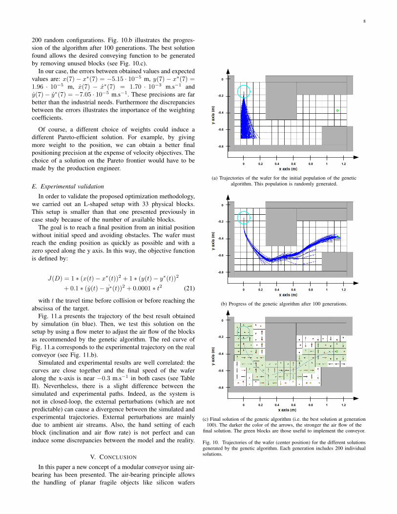
200 random configurations. Fig. 10.b illustrates the progres-sion of the algorithm after 100 generations. The best solutionfound allows the desired conveying function to be generatedby removing unused blocks (see Fig. 10.c).
In our case, the errors between obtained values and expectedvalues are: x(7) − x∗ (7) = −5.15 · 10 − 5 m, y(7) − x ∗ (7) =1.96 · 10 − 5 m, x(7) − x ∗ (7) = 1.70 · 10 − 3 m.s− 1 andy(7)− y ∗ (7) = −7.05 · 10− 5 m.s− 1. These precisions are farbetter than the industrial needs. Furthermore the discrepanciesbetween the errors illustrates the importance of the weightingcoefficients.
Of course, a different choice of weights could induce adifferent Pareto-efficient solution. For example, by givingmore weight to the position, we can obtain a better finalpositioning precision at the expense of velocity objectives. Thechoice of a solution on the Pareto frontier would have to bemade by the production engineer.
E. Experimental validation
In order to validate the proposed optimization methodology,we carried out an L-shaped setup with 33 physical blocks.This setup is smaller than that one presented previously incase study because of the number of available blocks.
The goal is to reach a final position from an initial positionwithout initial speed and avoiding obstacles. The wafer mustreach the ending position as quickly as possible and with azero speed along the y axis. In this way, the objective functionis defined by:
J(D) = 1∗(x(t)− x∗ (t))2 + 1∗(y(t)− y ∗ (t))2
+ 0.1∗(y(t)− y ∗ (t))2 + 0.0001∗t2 (21)
with t the travel time before collision or before reaching theabscissa of the target.
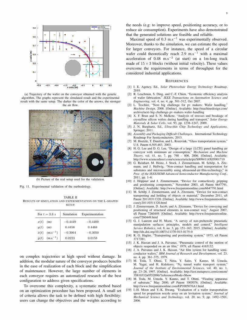
Fig. 11.a presents the trajectory of the best result obtainedby simulation (in blue). Then, we test this solution on thesetup by using a flow meter to adjust the air flow of the blocksas recommended by the genetic algorithm. The red curve ofFig. 11.a corresponds to the experimental trajectory on the realconveyor (see Fig. 11.b).
Simulated and experimental results are well correlated: thecurves are close together and the final speed of the waferalong the x-axis is near −0.3 m.s− 1 in both cases (see TableII). Nevertheless, there is a slight difference between thesimulated and experimental paths. Indeed, as the system isnot in closed-loop, the external perturbations (which are notpredictable) can cause a divergence between the simulated andexperimental trajectories. External perturbations are mainlydue to ambient air streams. Also, the hand setting of eachblock (inclination and air flow rate) is not perfect and caninduce some discrepancies between the model and the reality.
V. CONCLUSION
In this paper a new concept of a modular conveyor using air-bearing has been presented. The air-bearing principle allowsthe handling of planar fragile objects like silicon wafers
0 0.2 0.4 0.6 0.8 1 1.2
0
-0.2
-0.4
-0.6
-0.8
(a) Trajectories of the wafer for the initial population of the geneticalgorithm. This population is randomly generated.
0 0.2 0.4 0.6 0.8 1 1.2
0
-0.2
-0.4
-0.6
-0.8
(b) Progress of the genetic algorithm after 100 generations.
0 0.2 0.4 0.6 0.8 1 1.2
0
-0.2
-0.4
-0.6
-0.8
(c) Final solution of the genetic algorithm (i.e. the best solution at generation100). The darker the color of the arrows, the stronger the air flow of the
final solution. The green blocks are those useful to implement the conveyor.
Fig. 10. Trajectories of the wafer (center position) for the different solutionsgenerated by the genetic algorithm. Each generation includes 200 individualsolutions.
9
(a) Trajectory of the wafer on the conveyor obtained with the geneticalgorithm. The graphs represent the simulated result and the experimental
result with the same setup. The darker the color of the arrows, the strongerthe air flow.
(b) Picture of the real setup used for the validation.
Fig. 11. Experimental validation of the methodology.
TABLE IIRESULTS OF SIMULATION AND EXPERIMENTATION ON THE L-SHAPED
SETUP.
For t = 3.8 s Simulation Experimentation
x(t) (m) −0.4449 −0.4400y(t) (m) 0.4456 0.4468
x(t) (m.s1) −0.3064 −0.3050y(t) (m.s1) 0.0223 0.0158
on complex trajectories at high speed without damage. Inaddition, the modular nature of the conveyor produces benefitsin the ease of realization of each block and the simplificationof maintenance. However, the large number of elements ineach conveyor requires an automatized research of the bestconfiguration to address given specifications.
To overcome this complexity, a systematic method basedon an optimization procedure has been proposed. A small setof criteria allows the task to be defined with high flexibility:users can change the objectives and the weights according to
the needs (e.g: to improve speed, positioning accuracy, or toreduce air consumption). Experiments have also demonstratedthat the generated solutions are feasible and reliable.
Maximal speed of 0.3 m.s1 was experimentally observed.Moreover, thanks to the simulation, we can estimate the speedfor larger conveyors. For instance, the speed of a circularwafer could theoretically reach 2.9 m.s1 with a maximalacceleration of 0.48 m.s2 (at start) on a 1m-long trackmade of 15 3 blocks (without initial velocity). These valuesovercome the requirements in terms of throughput for theconsidered industrial applications.
REFERENCES
[1] I. E. Agency, Ed., Solar Photovoltaic Energy Technology Roadmap,2010.
[2] R. Leachman, S. Ding, and C.-F. Chien, “Economic efficiency analysisof wafer fabrication,” IEEE Transactions on Automation Science andEngineering, vol. 4, no. 4, pp. 501–512, Oct 2007.
[3] L. Teschler, “Next big challenge for pv makers: Wafer handling,”Machine Design, 2008. [Online]. Available: http://machinedesign.com/archive/next-big-challenge-pv-makers-wafer-handling
[4] X. F. Brun and S. N. Melkote, “Analysis of stresses and breakage ofcrystalline silicon wafers during handling and transport,” Solar EnergyMaterials & Solar Cells, vol. 93, pp. 1238–1247, 2009.
[5] J. N. Burghartz, Ed., Ultra-thin Chip Technology and Applications.Springer, 2011.
[6] Assembly and Packaging Difficult Challenges. International TechnologyRoadmap For Semiconductors, 2013.
[7] M. Hoetzle, T. Dunifon, and L. Rozevink, “Glass transportation system,”U.S. Patent 6,505,483, 2003.
[8] H. G. Lee and D. G. Lee, “Design of a large LCD panel handling airconveyor with minimum air consumption,” Mechanism and MachineTheory, vol. 41, no. 7, pp. 790 – 806, 2006. [Online]. Available:http://www.sciencedirect.com/science/article/pii/S0094114X05001710
[9] G. Reinhart, M. Heinz, J. Stock, J. Zimmermann, M. Schilp, A. Zitz-mann, and J. Hellwig, “Non-contact handling and transportation forsubstrates and microassembly using ultrasound-air-film-technology,” inProc. of the IEEE/SEMI Advanced Semiconductor Manufacturing Conf.,2011, pp. 1–6.
[10] J. Hoppner and J. Zimmermann, “Device for contactlessly grippingand positioning components,” November 2003, uS Patent 6647791.[Online]. Available: http://www.freepatentsonline.com/6647791.html
[11] M. Schilp, J. Zimmermann, and A. Zitzmann, “Device for non-contacttransporting and holding of objects or material,” December 2011, uSPatent 2011/0311320. [Online]. Available: http://www.freepatentsonline.com/y2011/0311320.html
[12] J. Zimmermann, D. Jacob, and A. Zitzmann, “Device for conveying andpositioning of structural elements in non-contact way,” August 2007,uS Patent 7260449. [Online]. Available: http://www.freepatentsonline.com/7260449.html
[13] G. J. Laurent and H. Moon, “A survey of non-prehensile pneumaticmanipulation surfaces: principles, models and control,” IntelligentService Robotics, vol. 8, no. 3, pp. 151–163, 2015. [Online]. Available:http://dx.doi.org/10.1007/s11370-015-0175-0
[14] R. G. Hagler, “Transporting and positioning system,” 1973, uS Patent3717381.
[15] J. K. Hassan and J. A. Paivanas, “Pneumatic control of the motion ofobjects suspended on an air film,” 1979, uS Patent 4165132.
[16] J. A. Paivanas and J. K. Hassan, “Air film system for handling semi-conductor wafers,” IBM Journal of Research and Development, vol. 23,no. 4, pp. 361–375, 1979.
[17] M. Toda, T. Ohmi, T. Nitta, Y. Saito, Y. Kanno, M. Umeda,M. Yagai, and H. Kidokoro, “N2 tunnel wafer transport system,”Journal of the Institute of Environmental Sciences, vol. 40, no. 1,pp. 23–28, 1997. [Online]. Available: http://iest.metapress.com/content/35810332n0552006/?referencesMode=Show
[18] M. Toda, M. Umeda, Y. Kanno, and T. Ohmi, “Floating apparatusof substrate,” May 2000, eP Patent 1005076. [Online]. Available:http://www.freepatentsonline.com/EP1005076A1.html
[19] I.-H. Moon and Y.-K. Hwang, “Evaluation of a wafer transportationspeed for propulsion nozzle array on air levitation system,” Journal ofMechanical Science and Technology, vol. 20, no. 9, pp. 1492–1501,2006.

10
[20] Y.-J. Kim and D. H. Shin, “Wafer position sensing and motion controlin the clean tube system,” in Proc. of the IEEE Int. Conf. on IndustrialTechnology, 2006, pp. 1315–1319.
[21] D. H. Shin, H. G. Lee, and H. S. Kim, “Wafer positioning control ofclean tube system,” in Proc. of the ACSE Conf., 2005.
[22] A. Berlin, D. Biegelsen, P. Cheung, M. Fromherz, D. Goldberg, W. Jack-son, B. Preas, J. Reich, and L.-E. Swartz, “Motion control of planarobjects using large-area arrays of mems-like distributed manipulators,”in Micromechatronics, 2000.
[23] D. K. Biegelsen, A. Berlin, P. Cheung, M. P. Fromherz, D. Goldberg,W. B. Jackson, B. Preas, J. Reich, and L.-E. Swartz, “Air-jet papermover: An example of meso-scale mems,” in SPIE Int. Symposium onMicromachining and Microfabrication, 2000.
[24] J. Wesselingh, R. van Ostayen, J. Spronck, R. Schmidt, and J. vanEijk, “Actuator for contactless transport and positioning of large flatsubstrates,” in Proc. of the EUSPEN Int. Conf., 2008.
[25] J. van Rij, J. Wesselingh, R. A. J. van Ostayen, J. Spronck, R. M.Schmidt, and J. van Eijk, “Planar wafer transport and positioning onan air film using a viscous traction principle,” Tribology International,vol. 42, pp. 1542–1549, 2009.
[26] J. Wesselingh, J. Spronck, R. van Ostayen, and J. van Eijk, “Contactless6 dof planar positioning system utilizing an active air film,” in Proc. ofthe EUSPEN Int. Conf., 2010.
[27] J. Luntz and H. Moon, “Distributed manipulation with passive air flow,”in Proc. of the IEEE/RSJ Int. Conf. on Intelligent Robots and Systems,2001, pp. 195–201.
[28] H. Moon and J. Luntz, “Distributed manipulation of flat objects withtwo airflow sinks,” IEEE Transactions on robotics, vol. 22, no. 6, pp.1189–1201, 2006.
[29] K. Varsos and J. Luntz, “Superposition methods for distributed manip-ulation using quadratic potential force fields,” IEEE Transactions onrobotics, vol. 22, no. 6, pp. 1202–1215, 2006.
[30] K. Varsos, H. Moon, and J. Luntz, “Generation of quadratic potentialforce fields from flow fields for distributed manipulation,” IEEE Trans-actions on robotics, vol. 22, no. 1, pp. 108–118, 2006.
[31] G. J. Laurent, A. Delettre, and N. L. Fort-Piat, “A new aerodynamictraction principe for handling products on an air cushion,” IEEE Trans-actions on robotics, vol. 27, no. 2, pp. 379–384, 2011.
[32] A. Delettre, G. J. Laurent, Y. Haddab, and N. L. Fort-Piat, “Robustcontrol of a planar manipulator for flexible and contactless handling,”Mechatronics, vol. 22, no. 6, pp. 852–861, 2012.
[33] A. Delettre, G. J. Laurent, N. L. Fort-Piat, and C. Varnier, “3-dofpotential air flow manipulation by inverse modeling control,” in Proc.of the IEEE Int. Conf. on Automation Science and Engineering, 2012,pp. 926–931.
[34] L. Li, Z. Sun, M. Zhou, and F. Qiao, “Adaptive dispatching rulefor semiconductor wafer fabrication facility,” IEEE Transactions onAutomation Science and Engineering, vol. 10, no. 2, pp. 354–364, April2013.
[35] J. E. Luntz, W. Messner, and H. Choset, “Distributed manipulationusing discrete actuator arrays,” The International Journal of RoboticsResearch, vol. 20, no. 7, pp. 553–583, 2001.
[36] M. Bedillion and W. Messner, “Control for actuator arrays,” TheInternational Journal of Robotics Research, vol. 28, no. 7, pp. 868–882, 2009.
[37] K. Furmans, C. Nobbe, and M. Schwab, “Future of material handling–modular, flexible and efficient,” in Proc. of the IEEE/RSJ Int. Conf. onIntelligent Robots and Systems, 2011.
[38] T. Kruhn, M. Radosavac, N. Shchekutin, and L. Overmeyer, “Decen-tralized and dynamic routing for a cognitive conveyor,” in AdvancedIntelligent Mechatronics (AIM), 2013 IEEE/ASME International Con-ference on. IEEE, 2013, pp. 436–441.
[39] K. T. McDonald, “Radial viscous flow between two parallel annularplates,” arXiv:physics/0006067, 2000.
Valerian Guelpa is a graduate of the NationalSchool of Mechanics and Microtechnologies (EN-SMM) of Besancon in France and received his Mas-ter degree of Mechatronics, Microsystems and Em-bedded Electronics from the University of Franche-Comte in 2013. As a Ph.D. student at the AS2M(Automatic Control and MicroMechatronic Systems)department of FEMTO-ST Institute, his researchinvolves microrobotics and visual measurements.
Guillaume J. Laurent is associate professor at theNational School of Mechanics and Microtechnology(ENSMM) in Besancon, France. He received theengineer degree in mechanics in 1999 and his Ph.D.in control systems and computer sciences from theUniversity of Franche-Comte in 2002. He is memberof the Automatic Control and Micro-MechatronicSystems Department of FEMTO-ST Institute. Hisexpertise and interests are in the field of micro-robotics, micromanipulation, distributed manipula-tion, and vision for microrobotics.
Bassem Dahroug received the Bsc degree inmechanical engineering from AAST (Alexandria,Egypt) in 2011 and the Msc degree in mechatron-ics and micro-mechatronics system from ENSMM(Besancon, France) and EPI (Gjon, Spain) in 2014.He is currently a PhD student at the AS2M depart-ment at the FEMTO-ST Institut where his researcharea is mainly centered on design and control ofmicro-robot for middle ear surgery.
Nadine Le Fort-Piat received her Ph.D. in ControlSystems and Signal Processing at the Universityof Technology of Compiegne (UTC) in 1984. Shebecame associate professor in 1984 at UTC andprofessor in 1998 at the National Engineering Schoolof Mechanics and Microtechnologies (ENSMM) inBesancon. She is a member of the Automatic Controland Micro-Mechatronic Systems Department of theFEMTO-ST Institute. Her research areas concernperception and advanced control strategies based onvisual servoing for micro and nanomanipulation.