Embed Size (px)
Citation preview

Modular C0NTR0L systemKS vario
CAN openINTERFACE protoCol
9499 040 69911VALID FR0M 09/2005

KSvario CANopen interface protocol
2 9499 040 69911 Preliminary
BlueControl® is a registered trademark ofPMA Prozeß- und Maschinen-Automation GmbH
©PMA Prozeß- und Maschinen-Automation GmbH. Printed in Germany.All rights reserved. No part of this document may be reproducedor published in any form or by any means without prior written
permission by the copyright owner.
This is a publication of PMA Prozeß- und Maschinen-Automation GmbH.
Data is subject to change without notice.
PMA Prozeß- und Maschinen-Automation GmbHP.O. Box 31 02 29
D 34058 KasselGermany
Limitation of warranty:No warranty is given for the absolute correctness of this manual, because despite utmost care,errors can never be avoided entirely. Hints are always welcome and will be gratefully accepted.
KSvario CANopen interface protocol
Preliminaryg 9499 040 69918 3
Table of contents Page
1. Introduction........................................................................................................................................................ 41.1 General ......................................................................................................................................................... 41.2 Technical data............................................................................................................................................... 41.3 Predefined Master/Slave Connection Set ..................................................................................................... 51.4 Commissioning the KSvario in the CANbus .................................................................................................. 6
2. Service Data Objects (SDO).............................................................................................................................. 73. Process Data Objects (PDO)............................................................................................................................. 9
3.1 Application .................................................................................................................................................... 93.2 Setting the communication parameters for ‘Receive PDOs’.......................................................................... 93.3 Setting the communication parameters for ‘Transmit PDOs’....................................................................... 103.4 Adjusting the mapping parameters of the PDOs ......................................................................................... 133.5 Reading the mapping parameters via CANbus ........................................................................................... 18
4. NMT services .................................................................................................................................................. 195. SYNC .............................................................................................................................................................. 206. LSS services ................................................................................................................................................... 21
6.1 Switch mode protocols ................................................................................................................................ 216.2 Configuration protocols ............................................................................................................................... 226.3 Inquiry protocols.......................................................................................................................................... 236.4 Identification Protocols ................................................................................................................................ 24
7. Saving and loading parameters (Store/Restore) ............................................................................................. 257.1 Non-volatile saving of parameters (Index 0x1010)...................................................................................... 257.2 Loading saved parameters (Index 0x1011)................................................................................................. 25
8. Heartbeat......................................................................................................................................................... 258.1 Configuration as Heartbeat Producer (Index 0x1017): ................................................................................ 258.2 Configuration as Heartbeat Consumer (Index 0x1016): .............................................................................. 25
9. Configuration and parametrising via the CANbus............................................................................................ 2610. CAN physical layer...................................................................................................................................... 28
10.1 ISO 11898-2 nodes ..................................................................................................................................... 2810.2 Bitrates and bus lengths.............................................................................................................................. 2910.3 Practical bus lengths ................................................................................................................................... 2910.4 Cable parameters........................................................................................................................................ 30

KSvario CANopen interface protocol
4 9499 040 69911 Preliminary
1. Introduction
1.1 GeneralThe KSvario is fitted with a CAN interface that is used to transmit all the data required for thecontroller's operation (parameters and configuration data). Similarly, a corresponding masterdevice (PLC or industrial PC) can be given access to all process data.In accordance with the CANopen standard, data transmission is structured in SDO (Service DataObjects) and PDO (Process Data Objects). Hereby, SDOs are intended for configuring andparametrizing bus subscribers, whilst PDOs are used for the usual operating values.
The communication services implemented in the KSvario are based on the CANopen ApplicationLayer and Communication Profile (CiA Draft Standard 301).
1.2 Technical data
• 2 SDO channels
• 4 Transmit PDOs (TPDO), synchronous/asynchronous
• 4 Receive PDOs (RPDO), asynchronous
• Mapping of PDOs• Standard operation• Multiplex operation with channel-wise transmission• Multiplex operation with indexed transmission
• Data format: Float, Fixpoint 1, and Integer
• Transmission speeds from 10 kbit/s up to 1 Mbit/s
• NMT services
• LSS services
• Heartbeat
• Store/Restore
• Predefined Master/Slave Connection Set

KSvario CANopen interface protocol
Preliminaryg 9499 040 69918 5
1.3 Predefined Master/Slave Connection SetThe Communication Object Identifiers (COB-IDs) in the KSvario are assigned in accordance withthe Predefined Master/Slave Connection Set. Exceptions hereby are the PDOs – specialsettings permit deviations from the Connection Set.
Object Function code COB-ID range Index in Object directory
Broadcast messages
NMT 0000 0 -
Sync 0001 0x80 0x1005h
Point-to-point messages
TPDO1 0011 0x181-0x0x1FF 0x1800
RPDO1 0100 0x201-0x27F 0x1400
TPDO2 0101 0x281-0x2FF 0x1801
RPDO2 0110 0x301-0x37F 0x1401
TPDO3 0111 0x381-0x3FF 0x1802
RPDO3 1000 0x401-0x47F 0x1402
TPDO4 1001 0x481-0x4FF 0x1803
RPDO4 1010 0x501-0x57F 0x1403
Default TSDO 1011 0x581-0x5FF 0x1200
Default RSDO 1100 0x601-0x67F 0x1200
LSS 1111 0x7E4/0x7E5
KSvario CANopen interface protocol
6 9499 040 69911 Preliminary
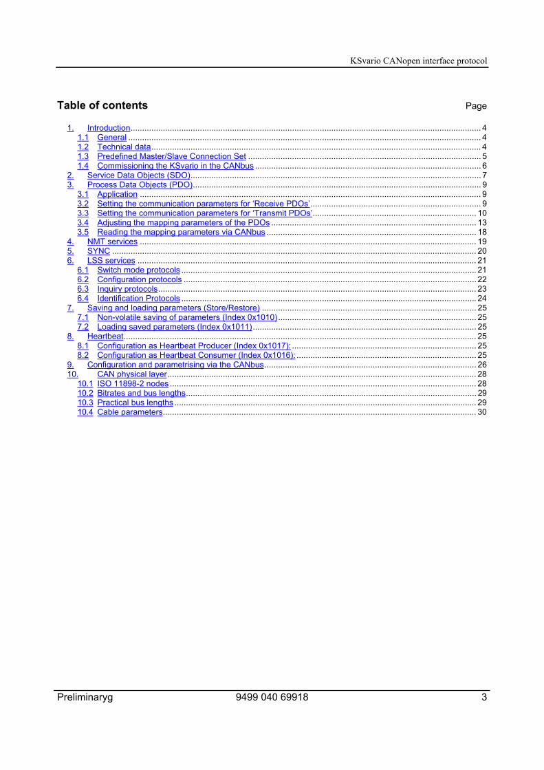
1.4 Commissioning the KSvario in the CANbusWhen delivered, the device node address is 255, and the bitrate is set to 20 kbit/s. The nodeaddress 255 starts the device in the LSS mode. If this not desired, any node address in therange from 1 to 127 can be selected. These settings can be carried out with the help of theBlueControl® via the BlueControl® interface, or by means of the LSS services via the CANbus.
When the KSvario has been started (with valid node address), it enters the "pre-operationalmode". Communication is possible via the CAN interface by means of SDOs. After configuringthe bus and the device, the Master must switch the KSvario into the "operating mode" (NMTstart), so that PDOs can also be used.The manner, in which PDOs are to be used, must be configured in advance. Hereby, adistinction is made between "asynchronous PDOs" and "synchronous PDOs".Asynchronous PDOs are transmitted in case of changed process values.Synchronous PDOs are transmitted on demand by the Master. For this, the Master transmits aSYNC frame.
KSvario CANopen interface protocol
Preliminaryg 9499 040 69918 7
2. Service Data Objects (SDO)
An SDO is defined logically for exactly two partners: 1 Master and 1 Slave. As the KSvario hastwo SDO channels, it is possible to access the KSvario simultaneously from two different SDOMasters. Data transmission via SDO is a confirmed service.
By means of the SDOs, controller configuration and parametrising can be done using singleaccesses. But also all operating data, which are usually transmitted via PDOs, can be addressedvia SDOs.
The COB-ID used is determined by the selected device address:For the Transmit SDO, this value lies in the range of 1409 – 1535 (0x581 – 0x5FF).For the Receive SDO, it lies in the range of 1537 – 1663 (0x601 – 0x67F)
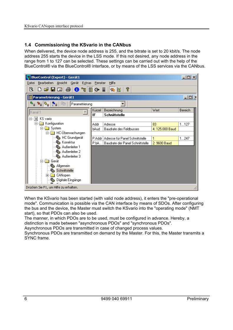
The 2nd SDO channel can be adjusted by means of BlueControl®. In the example shown, the 2nd
SDO channel is activated, and the CANbus address 112 is used, so that the COB-IDs 1520(0x5f0) and 1648 (0x670) are used. The addresses of both SDO channels must be different.The COB-ID of the 1st SDO channel is defined by the selected node address (predefinedconnection set).
Alternatively, a configuration via CANbus is possible. It is carried out using the objects with theIndex/Subindex 0x1201/1 and 0x1201/2 respectively.
Device-specific commands, such as change of operating mode (pre-operational mode, operatingmode, etc.), can only be executed via the 1st SDO channel.
KSvario CANopen interface protocol
8 9499 040 69911 Preliminary
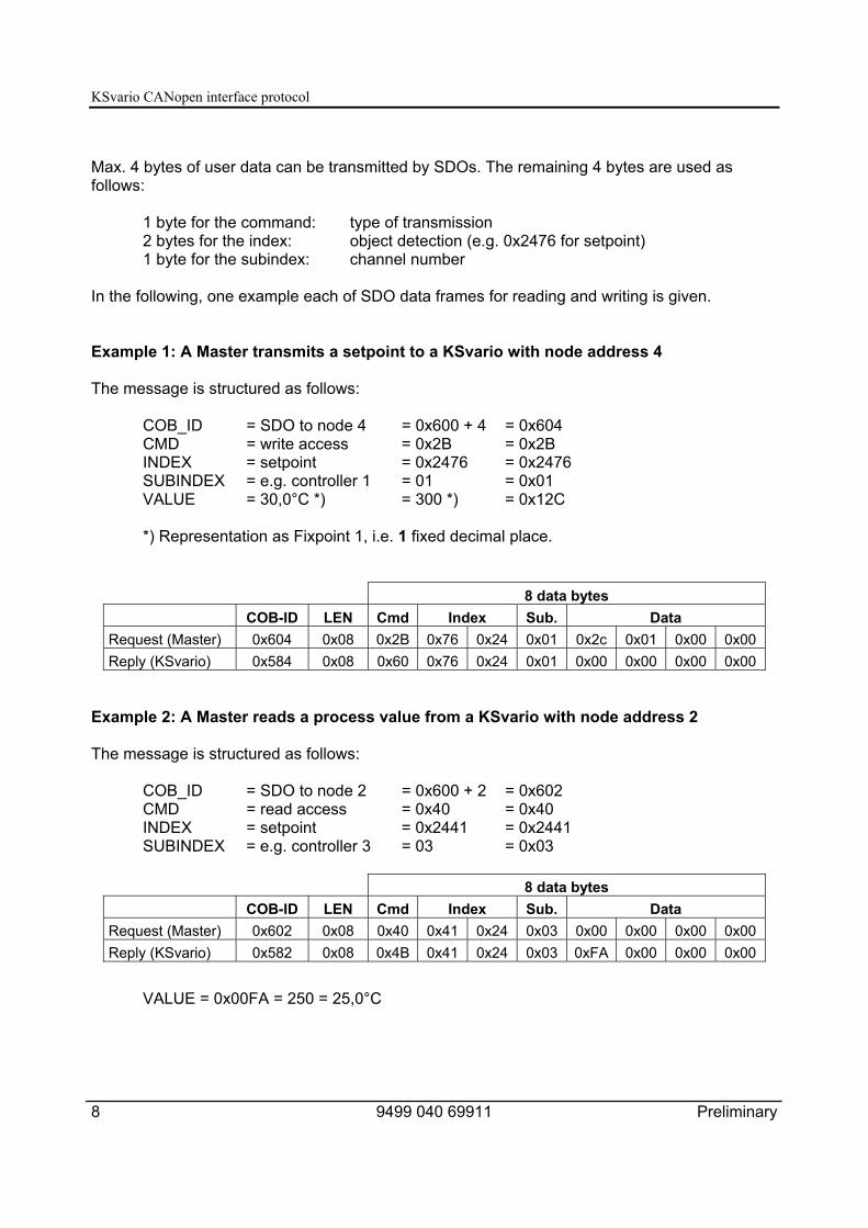
Max. 4 bytes of user data can be transmitted by SDOs. The remaining 4 bytes are used asfollows:
1 byte for the command: type of transmission2 bytes for the index: object detection (e.g. 0x2476 for setpoint)1 byte for the subindex: channel number
In the following, one example each of SDO data frames for reading and writing is given.
Example 1: A Master transmits a setpoint to a KSvario with node address 4
The message is structured as follows:
COB_ID = SDO to node 4 = 0x600 + 4 = 0x604CMD = write access = 0x2B = 0x2BINDEX = setpoint = 0x2476 = 0x2476SUBINDEX = e.g. controller 1 = 01 = 0x01VALUE = 30,0°C *) = 300 *) = 0x12C
*) Representation as Fixpoint 1, i.e. 1 fixed decimal place.
8 data bytesCOB-ID LEN Cmd Index Sub. Data
Request (Master) 0x604 0x08 0x2B 0x76 0x24 0x01 0x2c 0x01 0x00 0x00Reply (KSvario) 0x584 0x08 0x60 0x76 0x24 0x01 0x00 0x00 0x00 0x00
Example 2: A Master reads a process value from a KSvario with node address 2
The message is structured as follows:
COB_ID = SDO to node 2 = 0x600 + 2 = 0x602CMD = read access = 0x40 = 0x40INDEX = setpoint = 0x2441 = 0x2441SUBINDEX = e.g. controller 3 = 03 = 0x03
8 data bytesCOB-ID LEN Cmd Index Sub. Data
Request (Master) 0x602 0x08 0x40 0x41 0x24 0x03 0x00 0x00 0x00 0x00Reply (KSvario) 0x582 0x08 0x4B 0x41 0x24 0x03 0xFA 0x00 0x00 0x00
VALUE = 0x00FA = 250 = 25,0°C
KSvario CANopen interface protocol
Preliminaryg 9499 040 69918 9
3. Process Data Objects (PDO)
The KSvario provides 4 ‘Receive PDOs’ (RPDOs) and 4 ‘Transmit PDOs’ (TPDOs).PDOs are unconfirmed services with max. 8 bytes of user data.All incoming messages are processed in the sequence of their arrival. Preferential treatment ofspecial messages is not possible.Transmitting and receiving of PDOs is only possible in the operating mode.
3.1 ApplicationFor example, data transfer via PDOs makes sense if the process values and status values fromthe controller are to be updated continuously in the Master. In this case, asynchronous PDOswill be used, which automatically transmit any changed values from the controller to therespective Master. Another example would be the cyclical request for process values from anoperating unit. In this case, the KSvario can transmit PDOs that are synchronized with ameasuring cycle (SYNC EVENT).
3.2 Setting the communication parameters for ‘Receive PDOs’Only the COB-ID needs to be adjusted for the Receive PDO (RPDO). In general, a COB-ID fromthe range 385 – 1407 (0x181 – 0x57F) can be used for the PDO.In the predefined connection set, the selected device address is used to define the COB-ID.With a device address 5, the following COB-IDs apply:• RPDO1 517 (0x205)• RPDO2 773 (0x305)• RPDO3 1029 (0x405)• RPDO4 1285 (0x505)
The KSvario can only receive PDOs asynchronously.
3.2.1. Settings for ‘Receive PDO’ via CANbusSettings via CANbus are executed by means of the following objects:
• RPDO1 via Index 0x1400 and Subindex 1.• RPDO2 via Index 0x1401 and Subindex 1.• RPDO3 via Index 0x1402 and Subindex 1.• RPDO4 via Index 0x1403 and Subindex 1.
If the most significant bit of the 32-bit datum is set, the RPDO is not active.

KSvario CANopen interface protocol
10 9499 040 69911 Preliminary
3.2.2. Settings for ‘Receive PDO’ via the BlueControl® Engineering ToolIn the example shown, RPDO 1 is activated. Because the COB-ID is disabled, the device usesthe predefined connection set, which is 517 (0x205) in this case for a selected device address 5.
If an own COB-ID is to be selected, the corresponding entry must be activated with a tick in thecolumn ‘on’. Subsequently, a number in the range of 385 – 1407 must be entered in the column‘Value’.
3.3 Setting the communication parameters for ‘Transmit PDOs’The following values must be entered for the Transmit PDO (TPDO):
• COB-IDUsually, a COB-ID from the range 385 – 1407 (0x181 – 0x57F) can be used for the PDO.In the predefined connection set, the selected device address is used to define the COB-ID.The following COB-IDs are valid for a device address 5:
- TPDO1 389 (0x185)- TPDO2 645 (0x285)- TPDO3 901 (0x385)- TPDO4 1157 (0x485)
KSvario CANopen interface protocol
Preliminaryg 9499 040 69918 11
• Synchronous / asynchronous operation– 1 – 240 synchronous. The device generates a TPDO after receiving the 1st or 240th
SYNC signal.– 255 asynchronous. The device generates a TPDO if a value has changed in the
TPDO to be transmitted.
• Inhibit TimeDetermines the minimum time before the next TPDO can be generated. To prevent verymany messages being generated in case of fast changes of the values in the TPDO, theInhibit Time can be used to define a delay time. Adjustment is done in increments of 0,1 ms.If the value is set to 0, there is no delay.
• Event TimerDetermines the maximum delay time before the next TPDO is generated, also if there hasbeen no change of value. Adjustment is done in increments of 1 ms. If the value is set to 0,automatic transmission is disabled. If multiplexed data are transmitted (channel-wise or perIndex), the Event Timer is not active.
3.3.1. Settings for ‘Transmit PDO’ via CANbusSettings via CANbus are executed by means of the following objects:
• COB-ID- TPDO1 via Index 0x1800 and Subindex 1.- TPDO2 via Index 0x1801 and Subindex 1.- TPDO3 via Index 0x1802 and Subindex 1.- TPDO4 via Index 0x1803 and Subindex 1.
If the most significant bit of the 32-bit datum is set, the TPDO is not active.
• Synchronous / asynchronous operation- TPDO1 via Index 0x1800 and Subindex 2.- TPDO2 via Index 0x1801 and Subindex 2.- TPDO3 via Index 0x1802 and Subindex 2.- TPDO4 via Index 0x1803 and Subindex 2.
• Inhibit Time- TPDO1 via Index 0x1800 and Subindex 3.- TPDO2 via Index 0x1801 and Subindex 3.- TPDO3 via Index 0x1802 and Subindex 3.- TPDO4 via Index 0x1803 and Subindex 3.
• Event Timer- TPDO1 via Index 0x1800 and Subindex 5.- TPDO2 via Index 0x1801 and Subindex 5.- TPDO3 via Index 0x1802 and Subindex 5.- TPDO4 via Index 0x1803 and Subindex 5.
Subindex 4 is not used.

KSvario CANopen interface protocol
12 9499 040 69911 Preliminary
3.3.2. Adjustment for ‘Transmit PDO’ via BlueControl®In the example shown, TPDO 2 is activated.The fixed address 385 (0x181) has been assigned as COB-ID.This is an asynchronous PDO. The Inhibit Time has been set to 1 second, so the next TPDOcannot be generated before this delay time has elapsed.The Event Timer is set to 25 sec. Therefore, a TPDO is generated after 25 seconds at the latest,even if no value has changed.

KSvario CANopen interface protocol
Preliminaryg 9499 040 69918 13
3.4 Adjusting the mapping parameters of the PDOs
3.4.1. General information on adjustment of mapping parametersThe mapping parameters define which data are to be communicated in the PDOs. Theseparameters can only be adjusted via BlueControl®. Reading via the CANbus is possible.Only parameters and signals can be used. The data of RPDOs must be writable data. By meansof the selection options, BlueControl® ensures that these conditions are fulfilled.
Data can be transmitted both in the Integer as well as the Float format. Data that are transmittedin the Integer format, but are processed in the device as Float values, are transmitted as Fixpoint1 data (value is multiplied with factor 10).
The quantity of data that can be transmitted in a PDO depends on the data type (Integer or Floatformat) as well as the transmission method (standard or multiplex operation). If too many dataare selected, their entries are marked in red colour. These selected data will not be transmittedto the device by BlueControl®.
There are various possibilities of transmitting data in a PDO.
3.4.2. Standard operationIn this mode, fixed SDO parameters are assigned to the PDO. They are determined by the SDOparameter, and in addition by the subindex, if the data originates from the channel area. Thedata length depends on whether they have been selected from the Integer range 0x2000 (2bytes) or from the Float range 0x3000 (4 bytes). A combination of 2-byte and 4-byte data ispossible. Therefore, max. 4 items of data can be transmitted in the 8 bytes provided by a PDO.Not all the bytes of the PDO must be used.
Integer 1 Low
Integer 1 HighDatum 1: Defined as Integer in the controller, and is
read as an Integer value
Fixpoint 2 Low
Fixpoint 2 HighDatum 2: Defined as Float in the controller, and is
read as an Integer value
Float 3 bytes 1
Float 3 bytes 2
Float 3 bytes 3
Float 3 bytes 4
Datum 3: Defined as Float in the controller, and isread as a Float value

KSvario CANopen interface protocol
14 9499 040 69911 Preliminary
Which data are to be used is determined in BlueControl® by means of the mode “MappingTransmit-PDO1 – 4” or “Mapping Receive PDO1 – 4”.
In the above example, the following data are assigned to the TPDO1:• Effective process value of control loop 4• Status of the digital outputs 1...16• Output value of control loop 2
As the process value is transmitted in the Float format, the 4th value cannot be allocated.
In addition, it is possible to transmit the PDO data in multiplex operation, whereby there are twoalternatives:

KSvario CANopen interface protocol
Preliminaryg 9499 040 69918 15
3.4.3. Multiplex operation with channel-wise transmissionIt is possible to transmit the data by channel-wise multiplexing. Max. 3 items of data are defined,which are transmitted for every control loop in the device. The first 2 bytes of the PDO are usedto indicate the channel (control loop) for which the subsequent data apply. Data can betransmitted both in the Integer as well as the Float format.
Channel number
must always be “0”1 – 30 (if the value ‘0’ is transmitted, the data
cannot be used)
Fixpoint 1 Low
Fixpoint 1 HighDatum 1: Defined as Float in the controller, and is
read as an Integer value
Float 2 bytes 1
Float 2 bytes 2
Float 2 bytes 3
Float 2 bytes 4
Datum 2: Defined as Float in the controller, and isread as a Float value
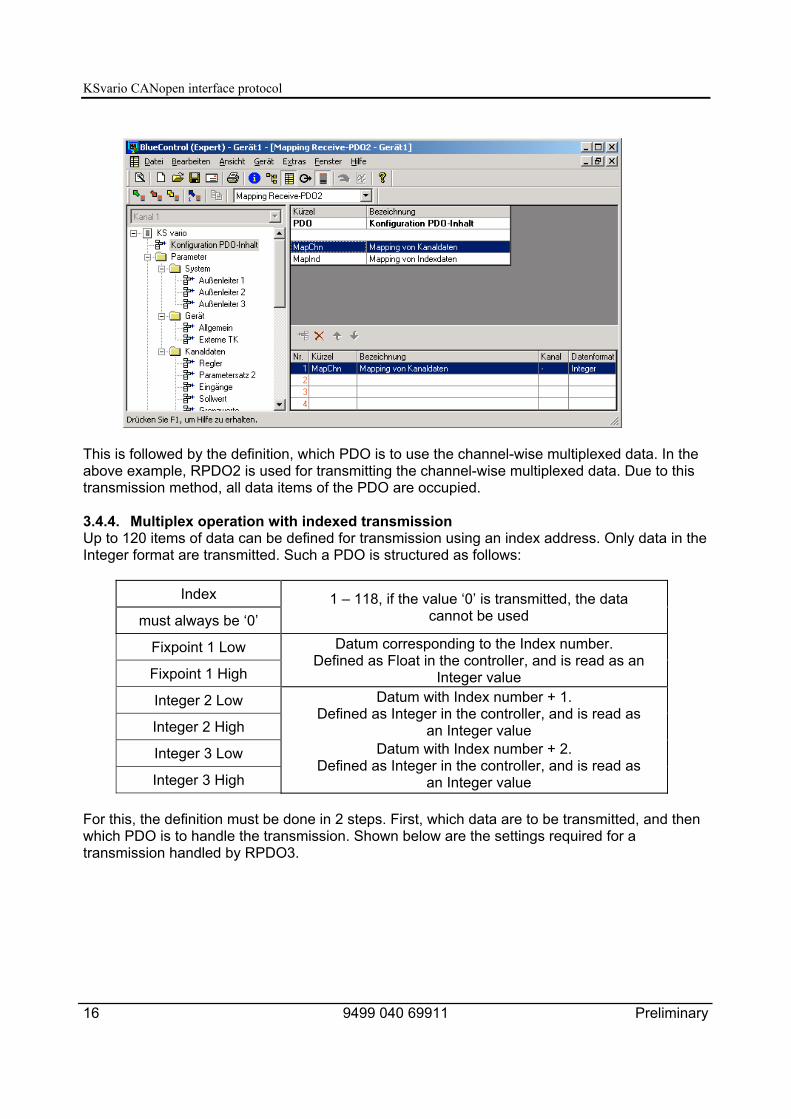
For this, the definition must be done in 2 steps. First, which data are to be transmitted, and thenwhich PDO is to handle the transmission.Shown below are the settings required for a transmission handled by RPDO2.
The data to be transmitted are defined. The 1st datum to be transmitted to the KSvario is themanual actuating value. The 2nd datum contains the setpoint. As the setpoint is transmitted in theFloat format, the 3rd datum is not available. The column ‘Channel’ indicates that settings can bemade for channels 1 – 12. These control loops are defined in BlueControl®. If data aretransmitted for other control loops, the values will not be accepted.
KSvario CANopen interface protocol
16 9499 040 69911 Preliminary
This is followed by the definition, which PDO is to use the channel-wise multiplexed data. In theabove example, RPDO2 is used for transmitting the channel-wise multiplexed data. Due to thistransmission method, all data items of the PDO are occupied.
3.4.4. Multiplex operation with indexed transmissionUp to 120 items of data can be defined for transmission using an index address. Only data in theInteger format are transmitted. Such a PDO is structured as follows:
Index
must always be ‘0’1 – 118, if the value ‘0’ is transmitted, the data
cannot be used
Fixpoint 1 Low
Fixpoint 1 High
Datum corresponding to the Index number.Defined as Float in the controller, and is read as an
Integer valueInteger 2 Low
Integer 2 High
Datum with Index number + 1.Defined as Integer in the controller, and is read as
an Integer valueInteger 3 Low
Integer 3 High
Datum with Index number + 2.Defined as Integer in the controller, and is read as
an Integer value
For this, the definition must be done in 2 steps. First, which data are to be transmitted, and thenwhich PDO is to handle the transmission. Shown below are the settings required for atransmission handled by RPDO3.
KSvario CANopen interface protocol
Preliminaryg 9499 040 69918 17
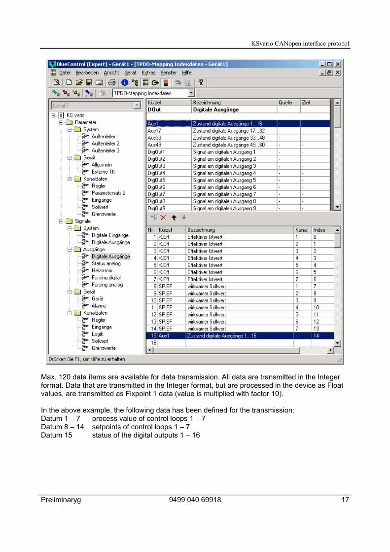
Max. 120 data items are available for data transmission. All data are transmitted in the Integerformat. Data that are transmitted in the Integer format, but are processed in the device as Floatvalues, are transmitted as Fixpoint 1 data (value is multiplied with factor 10).
In the above example, the following data has been defined for the transmission:Datum 1 – 7 process value of control loops 1 – 7Datum 8 – 14 setpoints of control loops 1 – 7Datum 15 status of the digital outputs 1 – 16

KSvario CANopen interface protocol
18 9499 040 69911 Preliminary
This is followed by the definition, which PDO is to use the indexed multiplexed data. In theabove example, TPDO3 is used for transmitting the indexed multiplexed data. Due to thistransmission method, all data items of the PDO are occupied.
The definition of the data for channel-wise or indexed access is always transmitted byBlueControl®, independent of the check box "Transmitted interface parameters".
3.5 Reading the mapping parameters via CANbusThe mapping parameters can be read via CANbus, whereby the following indices are used:
• RPDO1 via Index 1600 and Subindex 1 - 3.• RPDO2 via Index 1601 and Subindex 1 - 3.• RPDO3 via Index 1602 and Subindex 1 - 3.• RPDO4 via Index 1603 and Subindex 1 - 3.• TPDO1 via Index 1A00 and Subindex 1 - 3.• TPDO2 via Index 1A01 and Subindex 1 - 3.• TPDO3 via Index 1A02 and Subindex 1 - 3.• TPDO4 via Index 1A03 and Subindex 1 - 3.
The value 0x2FFF is transmitted for mapping index data, and the value 0x2FFE is transmittedfor mapping channel data.

KSvario CANopen interface protocol
Preliminaryg 9499 040 69918 19
4. NMT services
The following NMT services (COB-ID 0x00) are supported:
• Change to the operating mode (command code 0x01)• Change to the stop mode (command code 0x02)• Change to the pre-operational mode (command code 0x80)• Reset communication interface (command code 0x82)• Reset node (command code 0x81)
When the CAN network has been started, the KSvario is in the pre-operational mode. Thismeans that it can only be addressed via SDOs. If the KSvario is set into the operating mode,communication is also possible via the enabled PDOs.
Setting the KSvario into the operating mode:
2 data bytesCOB-ID LEN Command Node
0x00 2 0x01 <Number>
Setting the KSvario into the stop mode:
2 data bytesCOB-ID LEN Command Node
0x00 2 0x02 <Number>
Setting the KSvario into the pre-operational mode:
2 data bytesCOB-ID LEN Command Node
0x00 2 0x80 <Number>
Reset node:
2 data bytesCOB-ID LEN Command Node
0x00 2 0x81 <Number>
Caution: The reset node command executes a hardware reset of the KSvario, i.e. the device isnot addressable via the CANbus for a few seconds. All command parameters are reset to theirdefault values.

KSvario CANopen interface protocol
20 9499 040 69911 Preliminary
Reset communication:
2 data bytesCOB-ID LEN Command Node
0x00 2 0x82 <Number>
With a node ID ‘0’, this command is executed by all nodes; with any other node ID, only theaddressed subscriber will execute the command.Following the commands “Reset communications interface” and “Reset node”, the device is inthe pre-operational mode. This is also the status when the device is powered up. To permitcommunication via the PDOs, the device must be switched into the operating mode.
5. SYNC
As already described, the KSvario evaluates and transmits synchronous PDO data by means ofSYNC messages. For this, the corresponding KSvario controllers must be in the operatingmode, and synchronous PDOs must be configured.
SYNC messages are so-called "broadcasts" (messages to all subscribers in the network), andare transmitted by the Master as follows:
2 data bytesCOB-ID LEN Command Node
0x80 2

KSvario CANopen interface protocol
Preliminaryg 9499 040 69918 21
6. LSS services
LSS services in accordance with CiA/DS305 Version 1.1.1 are available. Restrictions andspecial extensions are detailed in the following service description.The associated COB IDs are 2021 (Master → Slave) and 2020 (Slave → Master), whereby theKSvario is always the Slave. With a node address of 255 (delivery condition) the device starts inthe LSS mode.
6.1 Switch mode protocols
6.1.1. Global switch-over into the operating/configuration modeM → S
0 1 2 3 4 5 6 7cs = 04 mode r r r r r r
cs LSS command specifiermode 0: switches to operating mode
1: switches to configuration moder reserved
6.1.2. Selective switch-over into the operating/configuration modeThe LSS status is toggled, whereby suitable subscribers on the bus are detected automatically.
M → S0 1 2 3 4 5 6 7
cs = 64 vendor ID r r r
M → S0 1 2 3 4 5 6 7
cs = 65 product ID r r r
M → S0 1 2 3 4 5 6 7
cs = 66 revision number r r r
M → S0 1 2 3 4 5 6 7
cs = 67 serial number r r r
S → M0 1 2 3 4 5 6 7
cs = 68 r r r r r r r
KSvario CANopen interface protocol
22 9499 040 69911 Preliminary
6.2 Configuration protocols
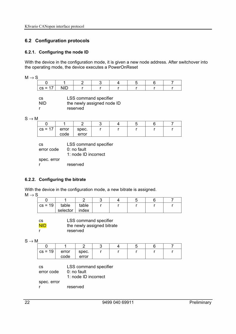
6.2.1. Configuring the node ID
With the device in the configuration mode, it is given a new node address. After switchover intothe operating mode, the device executes a PowerOnReset
M → S0 1 2 3 4 5 6 7
cs = 17 NID r r r r r r
cs LSS command specifierNID the newly assigned node IDr reserved
S → M0 1 2 3 4 5 6 7
cs = 17 errorcode
spec.error
r r r r r
cs LSS command specifiererror code 0: no fault
1: node ID incorrectspec. errorr reserved
6.2.2. Configuring the bitrate
With the device in the configuration mode, a new bitrate is assigned.M → S
0 1 2 3 4 5 6 7cs = 19 table
selectortableindex
r r r r r
cs LSS command specifierNID the newly assigned bitrater reserved
S → M0 1 2 3 4 5 6 7
cs = 19 errorcode
spec.error
r r r r r
cs LSS command specifiererror code 0: no fault
1: node ID incorrectspec. errorr reserved

KSvario CANopen interface protocol
Preliminaryg 9499 040 69918 23
6.3 Inquiry protocols
6.3.1. Inquiry of Vendor ID
M → S0 1 2 3 4 5 6 7
cs = 90 r r r r r r r
S → M0 1 2 3 4 5 6 7
cs = 90 vendor ID r r r
cs LSS command specifierr reserved
6.3.2. Inquiry of Product Code
M → S0 1 2 3 4 5 6 7
cs = 91 r r r r r r r
S → M0 1 2 3 4 5 6 7
cs = 91 product code r r r
cs LSS command specifierr reserved
6.3.3. Inquiry of Revision Number
M → S0 1 2 3 4 5 6 7
cs = 92 r r r r r r r
S → M0 1 2 3 4 5 6 7
cs = 92 revision number r r r
cs LSS command specifierr reserved
KSvario CANopen interface protocol
24 9499 040 69911 Preliminary
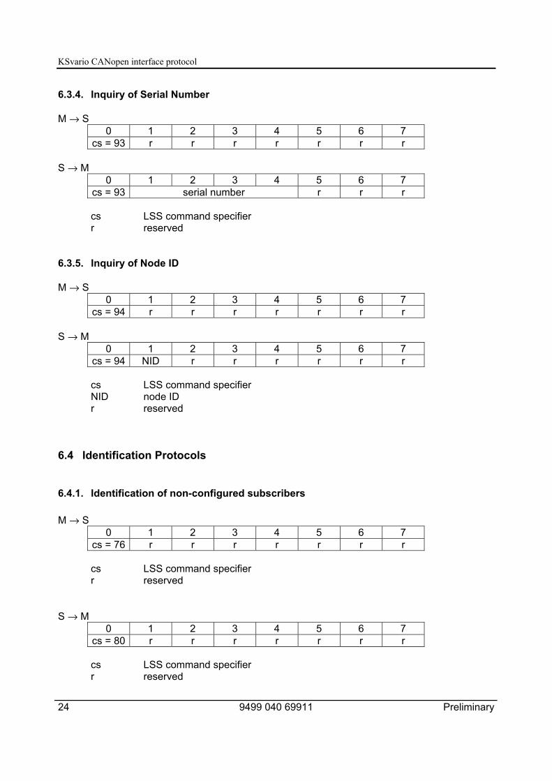
6.3.4. Inquiry of Serial Number
M → S0 1 2 3 4 5 6 7
cs = 93 r r r r r r r
S → M0 1 2 3 4 5 6 7
cs = 93 serial number r r r
cs LSS command specifierr reserved
6.3.5. Inquiry of Node ID
M → S0 1 2 3 4 5 6 7
cs = 94 r r r r r r r
S → M0 1 2 3 4 5 6 7
cs = 94 NID r r r r r r
cs LSS command specifierNID node IDr reserved
6.4 Identification Protocols
6.4.1. Identification of non-configured subscribers
M → S0 1 2 3 4 5 6 7
cs = 76 r r r r r r r
cs LSS command specifierr reserved
S → M0 1 2 3 4 5 6 7
cs = 80 r r r r r r r
cs LSS command specifierr reserved

KSvario CANopen interface protocol
Preliminaryg 9499 040 69918 25
7. Saving and loading parameters (Store/Restore)
7.1 Non-volatile saving of parameters (Index 0x1010)The following options are supported:
• All parameters (Subindex 1)• Communication parameters (Subindex 2)
There is no difference in behaviour, as only the communication parameters of the PDOs and the2nd SDO channel are stored in non-volatile EEPROM. After a Reset node or on power up, thedevice starts with these selected data.
7.2 Loading saved parameters (Index 0x1011)The following options are supported:
• All parameters (Subindex 1)• Communication parameters (Subindex 2)
There is no difference in behaviour, as only the communication parameters of the PDOs and the2nd SDO channel are reloaded. If changes that have been made to the communicationparameters of the PDOs or the 2nd SDO are to be cancelled, this command reloads theparameters stored in the non-volatile EEPROM. The command “Reset communicationsinterface” re-initializes the CANbus interface with the stored configuration.
8. Heartbeat
8.1 Configuration as Heartbeat Producer (Index 0x1017):For this purpose, the time in which a heartbeat signal is to be generated is entered in 1 mssteps. If the value ‘0’ is entered, no signals are generated.
8.2 Configuration as Heartbeat Consumer (Index 0x1016):Two monitoring values can be entered (Subindex 1 or Subindex 2):The time to be monitored is entered in 1 ms steps. The adjusted time must be significantlylonger (at least 100 ms longer) than the time adjusted at the Producer.The Producer's node ID is entered in the upper part of the time to be monitored.If the value ‘0’ is entered, there is no monitoring.

KSvario CANopen interface protocol
26 9499 040 69911 Preliminary
9. Configuration and parametrising via the CANbusThe simplest way to configure the KSvario is by means of the BlueControl® Engineering Tooland the BlueControl® interface. However, a configuration directly via the CANbus is alsopossible. For this, BlueControl® offers an export function for a complete list of parameters andconfiguration data. This download list contains the identical set of data that BlueControl® alsotransmits to the controller.
In this way, a download list (*.csv) can be stored in BlueControl® by means of <File>, <Export>,<Download list>.
It is possible to select whether the controller's internal Float data are to be stored as Float valuesor as Fixpoint 1 values in the download list.
The following printout shows a download list in the Float format:
Name;Index;Subindex;WertConfig;8193;0;1ConF_othr_UseStatErr;8203;0;0ConF_othr_Unit;8204;0;1ConF_othr_PowerOnContrOff;8205;0;0ConF_othr_IntMasterMod1;8207;0;0ConF_othr_IntMasterMod2;8208;0;0ConF_othr_IntMasterMod3;8209;0;0ConF_othr_IntMasterMod4;8210;0;0...PArA_SEtP_tSt.2;13424;2;10.0PArA_SEtP_Gefuehrt.2;9329;2;0PArA_Cntr_Pb1.2;13462;2;14.095582PArA_Cntr_Pb2.2;13463;2;14.095582PArA_Cntr_ti1.2;13464;2;1.9706573PArA_Cntr_ti2.2;13465;2;1.9706573PArA_Cntr_td1.2;13466;2;1.9706573PArA_Cntr_td2.2;13467;2;1.9706573PArA_Cntr_t1.2;13468;2;0.40000001PArA_Cntr_t2.2;13469;2;0.40000001...PArA_Lim3_L.30;13597;30;-10.0PArA_Lim3_H.30;13598;30;10.0PArA_Lim3_HYS.30;13599;30;1.0PArA_Out1_HcLim.30;13628;30;-32000.0PArA_Out2_HcLim.30;13658;30;-32000.0Config;8193;0;0

KSvario CANopen interface protocol
Preliminaryg 9499 040 69918 27
A datum is described in every line. Name, Index, Subindex, and the value are separated bysemicolons.At the start of transmission, the KSvario is switched into the configuration mode, and theconfiguration data and parameters are transmitted subsequently. At the end of transmission, theconfiguration mode is switched off again, and the controller re-initializes itself. Re-initializationtakes about 5 seconds before the controller starts working with the new data.

KSvario CANopen interface protocol
28 9499 040 69911 Preliminary
10. CAN physical layerThere are several standards concerning the CAN physical layer. The most important standardfor general application is the "CAN high-speed standard ISO 11898-2". The recommendationsgiven below are based mainly on this standard, and are valid regardless of the CAN protocolused (CANopen / DeviceNet).
10.1 ISO 11898-2 nodesA node that conforms to ISO 11898-2 consists of a µC with CAN controller (possibly integrated)that is connected with a CAN transceiver via Rx and Tx lines. In turn, the transceiver isconnected to the CANbus via the differential CAN-H and CAN-L leads. On the KSvario, this(transceiver) connection is galvanically isolated.
The nominal CANbus signal levels are called "Recessive" (nominal voltage of 2,5 V for CAN-Hand CAN-L) and "Dominant" (nominal 3,5 V for CAN-H, and 1,5 V for CAN-L).
KSvario CANopen interface protocol
Preliminaryg 9499 040 69918 29
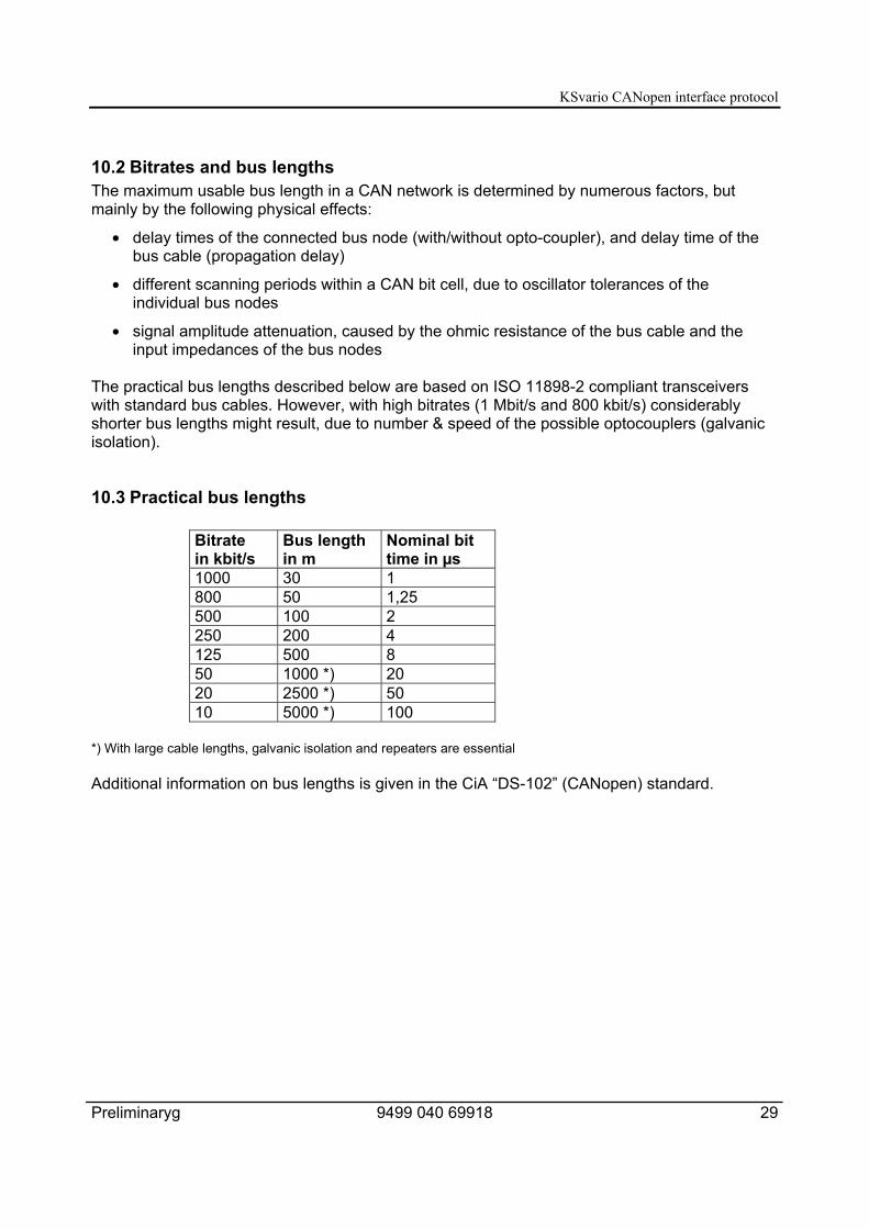
10.2 Bitrates and bus lengthsThe maximum usable bus length in a CAN network is determined by numerous factors, butmainly by the following physical effects:
• delay times of the connected bus node (with/without opto-coupler), and delay time of thebus cable (propagation delay)
• different scanning periods within a CAN bit cell, due to oscillator tolerances of theindividual bus nodes
• signal amplitude attenuation, caused by the ohmic resistance of the bus cable and theinput impedances of the bus nodes
The practical bus lengths described below are based on ISO 11898-2 compliant transceiverswith standard bus cables. However, with high bitrates (1 Mbit/s and 800 kbit/s) considerablyshorter bus lengths might result, due to number & speed of the possible optocouplers (galvanicisolation).
10.3 Practical bus lengths
Bitratein kbit/s
Bus lengthin m
Nominal bittime in µs
1000 30 1800 50 1,25500 100 2250 200 4125 500 850 1000 *) 2020 2500 *) 5010 5000 *) 100
*) With large cable lengths, galvanic isolation and repeaters are essential
Additional information on bus lengths is given in the CiA “DS-102” (CANopen) standard.

KSvario CANopen interface protocol
30 9499 040 69911 Preliminary
10.4 Cable parameters
ISO 11898-2 defines several DC and AC parameters for cables used in CANbus networks(typically, twisted cable pairs with defined electrical properties are used). The most important ACparameters are 120Ω cable impedance and a nominal propagation delay of 5 ns/m.Recommendations for bus cables and terminating resistors are given in the table below:
Bus cable (Z: 120 Ω, tp: 5 ns/m)Bus lengthSpecific
resistance Cable cross-section Terminating resistor Max. bitrate
0...40 m 70 mΩ/m 0,25 mm², 0,34 mm²AWG 23, AWG 22
124 Ω, 1% 1 Mbit/s@ 40 m
40...300 m <60 mΩ/m 0,34 mm², 0,6 mm²AWG 22, AWG 20
127 Ω, 1% *) > 500 kbit/s@ 100 m
300...600 m <40 mΩ/m 0,5 mm², 0,6 mm²AWG 20
127 Ω, 1% *) > 100 kbit/s@ 500 m
600 m...1 km <26 mΩ/m 0,75 mm², 0,8 mm²AWG 18
127 Ω, 1% *) > 50 kbit/s@ 1 km
*) With large cable lengths, a higher value for the terminating resistor (150...300 Ω) helps to reduce attenuation.
Further recommendations for CAN networks (especially with extended networks):
• Galvanic isolation is necessary with large lengths (e.g. 400 m of bus cable)
• Separate ground lead is advisable
• The voltage drop (potential difference) between the ground potentials of transceiversshould be kept low (less than 2 V). If necessary, the supply voltage should be connectedat the mid-point of the cable length.
• The overall input impedance of the bus nodes should be > 500 Ω
• If drop lines are used, they should be kept as short as possible in order to prevent/reducereflections.
More detailed information is available from CiA (CANopen), the relevant chip manufacturers, andin the Internet.

KSvario CANopen interface protocol
Preliminaryg 9499 040 69918 31

Subject to alterations without notice. © PMA Prozeß- and Maschinen-Automation GmbHBei Änderungen erfolgt keine Mitteilung. Postfach 310 229, D - 34058 KasselSous réserve de modifications sans avis préalable Printed in Germany 9499 040 69911 (08/2005)