Embed Size (px)
Citation preview

Product Catalog
Modular Assembly Systems

0.3
Accessories 8
Cabinets 1
Housings 2
Subracks 3 and Subrack Accessories
Industrial PCs 5
Wiring and Accessories 7
Power Supplies 6
Cassettes 4

0.4
SystemModule CompactPCI 6 U+1 URear I/O 3.33SystemModule CompactPCI 4 URear I/O 3.33SystemModule Configuration 3.34
Subrack Accessories
Single Parts
Side Panel Fi 3.36Side Panel Fs 3.37Side Panel RFI without Flange 3.38Side Panel InterRail® SNCF 3.40Flange F 3.41Flange without Nose 3.41Flange RFI 3.42Flange FP 3.43Flange for Wall Mounting 3.43Closing Profiles F and RFIF3 3.44Handle 3.44Side Panel Extender 3.45Side Panel Connector 3.45Horizontal Rails 3.46Cover Plates 3.54Rear Cover 3.56
Configurations
Subrack Divider 3.58 Horizontal Mounting Frame 3.59Partition Wall 3.60Separating Wall 3.60Wall and Door Installation Profiles 3.60Labelling Rail 3.61Locking Rail 3.61Label Strip 3.61Threaded Strips 3.62ZRail A 3.64Mounting Rail B 3.64Insulating Parts 3.65Card Guide ECONOMY 3.66Card Guide UNIVERSAL 3.67Card Guide with integrated push and pull assist 3.68Card Guide CONN 3.69Card Guide VIB 3.70Card Guide VARIO 3.71Card Guide IEEE 3.72Accessories for Card Guides 3.73PCB Locking 3.75
Index
The ”19-inch-Assembly System“
Cabinets
System Cabinet InterRack® 1.2Configuration 1.4Rack Versions 1.5System Cabinets 1.6Single Parts InterRack® 1.7
Housings
InterMeZo Housing 2.2Configuration 2.4Accessories 2.6, 2.9InterCase Desktop Housing 2.8InterLock Housing 2.9Foot Kit 2.9DiVar Housing 2.10
Intermas Subracks
Systematics of the Intermas Subracks 3.2Subrack FLEXIBLE 3.4Subrack FLEXIBLE Fi 3.6Subrack FLEXIBLE Fs 3.8Subrack RFISHIELDED 3.10 Measurement Configuration, Tests 3.12 Tests, Measurement Results 3.13 Implementation of the Shielding 3.14Subrack RFISHIELDED 3.15Subrack RFISHIELDED with Rear Cover 3.17Subrack RFISHIELDED IEEE 3.18Subrack RFISHIELDED Rear I/O 3.19Subrack InterRail® 3.20 Tests in accordance with SNCF NF standards and DIN EN 50155 3.22Subrack InterRail® 3.23Subrack InterRail® RFI 3.25Subrack InterRail® RFI with Rear Cover or for Front Panel in the Rear 3.26Subrack InterRail® RFIIEEE with Rear Cover or for Front Panel in the Rear 3.27Subrack InterRail® SNCF 3.28 and InterRail® SNCF RFI 3.29SystemModules CompactPCI 3.30SystemModule CompactPCI 3 URear I/O 3.32SystemModule CompactPCI 6 URear I/O 3.32

0.5
Front Panels and Handles
Blind Front Panels 3.78Blind Front Panels RFI 3.80Front Panels plugin, hinged 3.81Front Panels with Handle 3.82Handle and Handle Strip 3.85Front Panels with Ejector Handle 3.86Front Panels RFI with Ejector Handle 3.88Ejector Handle 4 HP 3.89Front Panels RFI with IEEE Handle 3.90 gray without hotswap 3.91 black with hotswap 3.92 Plastic Front Panel 3.93Snapin Handle 3.93Front Connector 3.94Front Connector FEE 3.95 Front Panel Support 3.95Screw Retainer, Grounding Bushing,Quick Lock E 3.96
Cassettes
Cassette with Extruded Side Walls 4.4Cassette with four Depth Profiles 4.5Cassette with Cover Hood 4.6Individual Parts of the Cassette 4.7Accessories for Cassettes 4.11Cassette with Heat Sink 4.14
Industrial PCs
Industrial PC Wallmount 5.2Industrial PC Box 5.3Industrial PC 19” 4 U Rackmount 5.4Industrial PC 19” 2 U Rackmount 5.5Industrial PCs customer specific electronic systems 5.6
Power Supplies
Power supplies PKSeries MONOVOLT 6.2Power supplies PKSeries BIVOLT 6.4Power supplies PKSeries TRIVOLT 6.6Power supplies VPSeries, 40 and 50 6.8Power supplies VPSeries, 80 and 150 6.10Power supplies ECSeries MONOVOLT 6.12Power supplies ECSeries TRIVOLT 6.13Power supplies GKSeries TRIVOLT 6.14
Index
Wiring and Accessories
Connectors Coding Key 7.2 Connectors Styles B, C, D and E 7.3 Connectors Styles F, H and R 7.4CrimpSnapInContacts 7.5CrimpPliers 7.5Accessories for Connectors 7.5Cover for Euroboards 7.7Plastic Interface Housings 7.8Plastic Guide Components 7.10Accessories for Plastic Interface Housings 7.13Metal Interface Housings 7.14Metal Interface Housings RFI 7.15Metallized Guide Components 7.16Metal Guide Components 7.17Accessories for Metal Interface Housings 7.18Insulated Bus Bar 7.20
Accessories
19” CrossFlow Fan 8.219” Fan Unit 1 U 8.3UFanRail® cooling solution for railway applications 8.4PCBA monitoring board 8.5RFI Springs 8.6RFI Fabric Gasket 8.9
Appendix
List of OrderNumbers 9.2Glossary 9.9

0.6
The ”19-inch-Assembly System“
The socalled 19inch assembly system consists of a wide range of mechanical and electromechanical components matched to each other in terms of their dimensions and can be regarded as a „mechanical construction kit“ for assembling electronic devices and systems.
The ”19inch assembly system“ was first presented in 1970 at the Hanover Trade Fair by AEG Telefunken (Intermas Modular Assembly Systems). The first application areas of this revolutionary development were industrial electronics followed by power station control engineering and traffic engineering. Today the system is in use worldwide in almost all areas of industrial electronics such as telecommunications, military technology, medical technology, measurement and control technology etc.
The 19 inches originated in the width of equipment frontpanels in accordance with the USA standard C839. In view of the frequent need to combine European and American equipment in a single system the width and
(cp.: ”The Modular 19”System“, Hesse, 1991, side 43)
the height increments of the 19inch front panel became the starting point for the DIN 41494 and IEC 60 2971 standards. Although the 19inch (482.6 mm) dimension is only used once as the width specification for the front panels of plugin units and subracks, it has given its name to the modular assembly system. All system dimensions are defined in mm. The correct designation should therefore more correctly be 482.6 mm technology, a term which is also used in DIN 41 494, the German standard for the 19” assembly system.
All necessary dimensions were defined in the German DIN 41 494 standard, in IEC Publication 60 297 and in the USA standard ANSI/IEEE 1101.
The aim of the standardization was to make it possible to combine different system components without problems and to ensure compatibility between different devices and modules as the basis for the specialization of individual manufacturers which resulted from global division of labor.
DIN standards and IEC publications
System levelDINstandards
IECpublications
DINstandards
IECpublications
DINstandards
IECpublications
Level 4Racks
Table Top Housings Racks Cabinets
DIN 41494 IEC 602971/2 DIN 41494 IEC 602971/2 DIN 41494 IEC 602971/2
Level 319”Front and rear pane and subracks
19”front panel 19”subracks 19”rear panel
DIN 41494 IEC 602973 DIN 41494 IEC 602973 DIN 41494 IEC 602973
Level 2Subassembly
PCB Plug in block Plug in unit
DIN 41494 IEC 602973 DIN 41494 IEC 602973 DIN 41494 IEC 602973
Level 1Components
Subassemblys at front panel Cards Connectors
DIN 41494 IEC 602973 DIN 41494 IEC 602973 DIN 41494 IEC 603033

0.7
The modular structure
The modular structure of the socalled 19” assembly system allows components of one level to be freely combined with one another without problems and used in assemblies of the next higher level.
In addition to the 19” front panel, the dimensions of the Euroboard (100 x 160 mm), the componentfitting and wiring grid on the PCB (2.54 mm) and the external dimensions for cabinets formed the initial dimensions for the modular ”19” assembly system“.
(Cp.: ”The Modular 19”System“, Hesse, 1991, side 17)
The ”19-inch-Assembly System“
�����������������������
���������������������
���������������������
�������
����
����������������� � ��������������������
�������
������������
� �� �����
��������������������
� �����
�������������
���������������������
� ����������
���������������������
���
����������������� � ����
����������������� � ����
�� ������������������ ������ ���

0.8
The protection requirements depend on sensitivity of the installed electronics and on the interference levels at the installation location.
Protection Requirements
2. Protection of the modules against external influences such as mechanical stresses as a result of vibration or shock, or infiltration of foreign bodies and humidity and also highfrequency interference signals.
EMI protection
Electromagnetic interference basically results from three different types of signals:√ sinusoidal permanent signals of fixed frequency√ broadband permanent signals(fundamental frequency with harmonics)√ transient signals(short period impulse)
In order to adequately counteract such interference factors the paneling elements are conductively connected to one another or bonded to one another using appropriate RFI gaskets.
The protection requirements can be divided into:
1. Protection of the surrounding environment against interference, for example RF radiation, emitted by the device or protection against contact with live components.
(Cp.: ”The Modular 19”System“, Hesse, 1991, side 127)
(Cp.: ”The Modular 19”System“, Hesse, 1991, side 127)

0.9
IP-Protection Classes (IP-Code) IEC 60 529 / EN 60 529
�����������������������������������������������������
� ���������������������
� � ��������� ������������
��� ������� �������������������
� � ��������� ���
����������������� ������������������������
� � ��������������������������������
����������� ������������������������
� � �������������������������������
������������� �����������������������
�������������������
���������������� �������������������
�������������������
����������
������ ���������
�������������
� ���������������������
� � ������������������ ����������
� � ������������������ ��������� ��������������������������
� � ������������������������������������ ������������������
� � �����������������
� ����������������
� ����������� ����������
� � ���������������
� � ����������������

0.10
Our ultimate goal is achieving a competitive advantage through competent advisory services combined with high quality and environmental awareness of our employees.
Quality policy
Quality and competitiveness of Intermas products and services are driven by customer requirements and expectations as well as international market standards. Therefore, every Intermas employee is dedicated to fulfil these requirements constantly and entirely.
Customer orientation and customer satisfaction
In order to improve the customer satisfaction consultation services are offered at any stage of the product life cycle. Our management informs customers about technical innovations.Intermas offers expertise in developing technical solutions through a dialogue with customers. A certified quality management system according to DIN EN ISO 9001 is in place.
DIN EN ISO 9001:2008

1.1This catalog contains stock and standard parts. Other products and sizes on request.
Cab
inet
s
System Cabinet InterRack®
System Cabinet InterRack
A sophisticated, systematically constructed cabinet system for electrical engineering applications, e.g. as:√ a universal 19” cabinet√ a lowvoltage cabinet√ a data and network cabinet
Also excellently suitable for your own designs or special solutions, e.g. as:√ a training cabinet√ for patch panels or in√ maintenance and control engineering√ military technology√ traffic engineering
In short: This cabinet meets all your requirements and desires.

This catalog contains stock and standard parts. Other products and sizes on request.1.2
Cab
inet
s
System Cabinet InterRack®
DescriptionThe InterRack system cabinet is made of steel and is easy to assemble using screws. Profiles and paneling elements are galvanized. The customer can choose between two colors of paint finish. The rack variants and assembly elements provide the capability for individual configuration.Protection classes IP 40 and IP 54 are achieved thanks to the use of siliconfree seals.
This cabinet stands out due to its enormous flexibility of the configuration and extension options.
√ Consistent assembly in the 25mmspace grid enables appropriate graduation in terms of width, height and depth.
√ Easily incorporated into CAE and CADsupported development projects.
√ Each level can be used for assembly using only a few system elements.
√ Selftapping screws allow simple and fast assembly and dismantling and ensure tight and electrically conductive connections.
√ Conducting surfaces and the replaceable system elements ensure excellent EMC characteristics.
DeliveryAs a completely assemled and painted cabinet. Unassembled components on request.
Technical DataStandards compliant with DIN 41 488, IEC 60 2971 and 2, IEC 60 917
Width grid assembly in a 25 mm grid
Depth grid assembly in a 25 mm grid
Materialloading profiles and corner connectors: aluminumother parts: galvanized steel
Finish standard: RAL 7032 or as required by the customer
Protection class compliant with DIN 40 050 IP 40 and IP 54contact protection in accordance with VDE 0160
Utilization category 25 °C, +70 °C, 75% relative humidity
Protective groundingall metal parts are electrically bonded to one another following assembly in accordance with VDE 100/12.65, § 6 Nb

1.3This catalog contains stock and standard parts. Other products and sizes on request.
Cab
inet
s
Sytem Cabinet InterRack®
Cabinet example√ Rack A√ Mounting plate√ Frontdoor, right opening√ Rear panel√ Base panel√ Top panel closed√ Swing handle√ 130° hinges
√ With side panel protection class IP 40
Sealing of the system cabinet InterRack to protection class IP 54
Sealing of the door Sealing of the paneling parts
RFI-shielding of the door of the system cabinet InterRack

This catalog contains stock and standard parts. Other products and sizes on request.1.4
Cab
inet
s
Configuration System Cabinet InterRackCabinet pieces __________
Rack version A version B version C version Dheight: ___________ mmwidth: ___________ mmdepth: ___________ mm
Color rackColor paneling parts
RAL __________RAL __________
Side panel adding:
left left
right right
Rear panel
Door opening
front rear
left left
right right
Double door front rear
Hinges 130 degree 180 degree
Door lock swing handle key plate
dummy element double bit 3 mm short cylinder keyed alike
square double bit 5 mm
Top panel closed labyrinth perforated raised
Base panel closed divided
Mounting plate galvanized color RAL ______________
Hinged frame opening: left 130 degree
right 180 degree
19” unit support front rear
Protection class IP ______
RFI-shielded
Accessories Adaptor Document box U-strut piece______
Logo strip Universal angle piece______ Lifting eye (kit with 4 pieces)
Base
Notes _______________________________________________________________________________
_______________________________________________________________________________
_______________________________________________________________________________
_______________________________________________________________________________
Configuration
Please ask your local representative for yourindividual configuration.
You find your contact person on our homepage:www.intermas-el.com
Hei
ght 2
50
240
0 m
min
25
mm
spa
ce g
rid
Width 250 2400 mm
in 25 mm space grid
Depth 250 2400 mm
in 25 mm space grid

1.5This catalog contains stock and standard parts. Other products and sizes on request.
Cab
inet
s
Rack version Afor stand alone cabinets with front door.
Rack version Bfor stand alone cabinets with front and rear door.
Rack version Cfor protected and separated regions, all sides prepared for covering panels.
Rack version Dfor frame type switchboards and distribution jumper rings.
Rack Versions
Rack constructionThe rail profiles are rolled from galvanized sheet steel. This ensures optimal corrosion protection, including the cut edges.Two versions of rail profiles are available, rail profile W and rail profile V. Plugin corner connectors made of diecast aluminum ensure stable connection in all three axes. The rail profiles are then screwed to the gusset plate.
This method of construction allows assembly of any cabinet rack with an edge length of 250 to 2400 mm. Individual switch racks or patch panels can also be constructed just as easily.

This catalog contains stock and standard parts. Other products and sizes on request.1.6
Cab
inet
s
System Cabinet InterRack®
Ordering details system cabinet
height[mm]
width [mm]
depth[mm]
1 front door order no. 409.
1 front door 1 rear door order no. 409.
double door order no.409.
InterRack 1200 x1000 x 400 1200 1000 400 166 261InterRack 2000 x 600 x 500 2000 600 500 166 262 166 263 166 264InterRack 2200 x 900 x 600 2200 900 600 166 265 166 266
Deliveryquantityper kit1 door
quantity per kit 2 doors
quantity per kitdouble door
Rack 1 1 1Door front/rear (130°)Hinges 130°, left opening 1 2 1
Side panels 2 2 2Rear panel 1 1Top panel closed 1 1 1Swing handle 1 2 2

1.7This catalog contains stock and standard parts. Other products and sizes on request.
Cab
inet
s
Rail Profiles
��
�����������
��������������������
����
�
�� ����
�
�
����� �� ��
��
�����������
�����������������
����
���
�� ���
�
�
�
����� �� ��
Rail ProfilesThe rail profiles are rolled from galvanized sheet steel. This ensures optimal protection against corrosion including the cut edges. Two Versions of rail profiles are available.Rail profile VRail profile W
Material: steelFinish: galvanized
Rail Profile WFor use as height, depth, width profile and dividing profile.
Length: 6360 mm
order no.: 409. 074 057
Rail Profile VFor use as height profile and dividing profile.
Length: 6360 mm
order no.: 409. 074 056
Finished length for rail profilesrack nom. width[mm]
length [mm]
m = number spacegrid
400 299 12 500 399 16 600 499 20 900 799 321000 899 361200 1099 442000 1899 762200 2099 84

This catalog contains stock and standard parts. Other products and sizes on request.1.8
Cab
inet
s
Corner Connector, Gusset Plate A and B,19”-Unit Support
19”-Unit SupportAre mounted vertically, depth variable in 25mmspace grid. For mounting of 19”equipment.
Material: steelFinish: galvanized, colorless chromated
Corner ConnectorFor connecting the rear profiles.
Material: aluminum die castingFinish: untreated
order no.: 409. 050 688
Gusset Plate AFor fastening the rack corner.
Material: steelFinish: galvanized, colorless chromated
order no.: 409. 131 354
Accessories
Cylinder head screw M 8 x 14(Torx T40) DIN 7500
Minimum order quantity: 10 pieces
order no.: 409. 132 778
Gusset Plate BFor fastening the rack corner.To get maximum free space for assemblies and for fastening with screws M 8.
Material: steelFinish: galvanized, colorless chromated
order no.: 409. 167 416
Ordering details for cabinet height[mm]
length [mm]
order no. 409.
19”unit support 2000 2000 1866.45 078 64119”unit support 2200 2200 2044.70 078 646

1.9This catalog contains stock and standard parts. Other products and sizes on request.
Cab
inet
s
U-Strut, Universal Angle, Door Hinge 180°
U-StrutAs support for unit support and fixturesin 25mmspace grid. 2 versions are available:1. For mounting from outside the cabinet.2. For mounting from inside the cabinet.This version is especially suitable for later installations.
Material: steel, 3 mm thickFinish: galvanized, colorless chromated
Accessories
Hexagon Head Screw M 6 x 12
Minimum order quantity: 10 pieces
order no.: 409. 050 567
Ordering details
for cabinet depth/width [mm]
outside order no. 409.
insideorder no. 409.
UStrut 400 400 049 677 132 601UStrut 500 500 049 679 132 603UStrut 600 600 049 680 132 604UStrut 800 800 049 681 132 605UStrut 900 900 049 682 132 606
Universal AngleTo fastening of 19”unit support and accessories.
Material: steel, 3 mm thickFinish: galvanized, colorless chromated
order no.: 409. 132 240
Accessory
Hexagon Head Screw M 6 x 12
Minimum order quantity: 10 Pieces
order no.: 409. 131 550
Door Hinge 180°≠For fixing all types of cabinet doors with a 180° opening angle.
Material: aluminumFinish: black anodized
Delivery: 3 hinges, 3 hinge pinsMounting parts
order no.: 409. 069 369

This catalog contains stock and standard parts. Other products and sizes on request.1.10
Cab
inet
s
Standard Adaptor KitTo bolt together additional cabinets.
Material: steelFinish: galvanized, colorless chromated
Delivery: 8 threaded spacers Mounting parts
order no.: 409. 132 464
Lifting Eye Kit
Material: steelFinish: galvanized, colorless chromated
Delivery: 4 lifting eyes Mounting parts
order no.: 409. 132 735
Document BoxDIN A4, upright, self adhesive
Material: Polystyrene, shock resistentFinish: RAL 9002
order no.: 409. 068 760
Custom Logo StripFor the rack above the door.Self adhesive
Material: aluminum 2 mm thickFinish: anodized (paintable and printable)
Standard Adaptor, Lifting Eye,Document Box, Custom Logo Strip for Cabinets
Ordering detailslength [mm]
order no. 409.
Custom logo strip 600 594 049 668Custom logo strip 900 894 049 670Custom logo strip 1000 994 069 302

2.1This catalog contains stock and standard parts. Other products and sizes on request.
Hou
sing
s
InterMeZo Housing
√ Design front√ Functional front√ Variable in three dimensions√ Can be RFIshielded√ Mechanical protection up to IP 54
InterCase Desktop Housing
√ Easy construction√ Service friendly√ Variable dimensions√ Can be RFIshielded
DiVar Housing
√ 19” rack mounted for customized housing√ Unrestricted configuration and installation √ Cover plates removable
Housings
InterLock Housing
√ Covering of subracks√ Easy mounting without screws

This catalog contains stock and standard parts. Other products and sizes on request.2.2
Hou
sing
s
2. Easy to accessFor quick access to the installed electronics the cover plates are pressed into profiled grooves and secured with two screws.
3. RFI shieldingThe side walls are pressed into profile grooves; contact elements ensure RFIshielded bonding.To achieve effective protection of the housing against dust and water the cover panels, the rear wall and the door can all be fitted with seals.
InterMeZo Housing
RequirementsA modern housing flexible in its applications, with a modular design, can be RFIshielded and ventilated, in an attractive design and at a reasonable price: InterMeZo
Construction1. Housing frameThe InterMeZo housing is based on a framework construction consisting of profiles and corner connectors. This flexible design also enables fast and costeffective assembly of individual housing sizes

2.3This catalog contains stock and standard parts. Other products and sizes on request.
Hou
sing
s
InterMeZo Housing
2. Functional frontFor higher protection against dust and water as well as EMC shielding.
VersionsThe InterMeZo housings are available to assembly 19” or metric subracks. Alternatively, any dimensions for variable applications are possible.For all versions the possibility exists to choose between the following types.
1. Design frontThis version has been constructed in terms of a harmonic front design for use with a wide range of applications.
4. Mechanical sealingTo achieve effective protection of the housing against dust and water the cover panels, the rear wall and the door can all be fitted with seals.
5. Recessed gripsGrips for easy transportation are formed by the recessed mounting of the side walls.
6. Equipment supportsSubracks can be installed variably as the housing depth permits.
7. Chassis panelsThe depth profiles are provided with grooves in which chassis panels or similar can be fitted at any depth with the aid of spring nuts.
SummaryThe InterMeZo housing from Intermas is a modular and costeffective housing solution for highquality industrial electronics in a visually attractive design, developed for the highest possible flexibility and simplest possible assembly, with expansion capabilities for more demanding needs, compliant with stringent EMI/ESD protection specifications, and with extensive configuration options to fulfil applicationspecific requirements.
Technical data
Materials
casing: aluminum profilescorner connectors: diecast zincfeet: ABSother parts: 0.8 mm galvanized sheet steel
Finish
standard for rear wall and cover panels: painted dark gray (RAL DS 5500)standard for casing and side walls: painted light gray (RAL DS 7000)feet: dark gray

This catalog contains stock and standard parts. Other products and sizes on request.2.4
Hou
sing
s
Configuration InterMeZo HousingHousing pieces __________
Dimension
height:width:depth:
3 U 84 HP 300 mm 400 mm 500 mm
6 U 42 HP
other:height: ____ U or _________ mmwidth: ____ HP or _________ mmdepth: _________ mm
Design
design front front rear
functional front front rear
Color casing, side wall RAL DS 7000 RAL____________
Color rear wall, panels RAL DS 5500 RAL____________
Louvers in bottom panel top panel rear panel
Front Casing door Plexiglass door Front panel anodized RAL ____________
19” unit support front rear
Protection class IP _______
RFI-shielding
Accessories
Rear panel Side bars
Wheels Subplate
Carry handles
Mounting material for subrack and front panels kit______ pieces
Notes
________________________________________________________________________________
________________________________________________________________________________
________________________________________________________________________________
________________________________________________________________________________
InterMeZo HousingConfiguration
Please ask your local representative for yourindividual system configuration.
You find your contact person on our homepage: www.intermas-el.com
Depth 140 600 m
m
in mm
increments
Hei
ght
120
70
0 m
min
mm
incr
emen
ts
Width 120 600 mm
in mm increments

2.5This catalog contains stock and standard parts. Other products and sizes on request.
Hou
sing
s
InterMeZo Housing
bottom
top
�����
�����
�����
���
�����
�
���������
�����
�����
��
����
�
Ordering details for assembled InterMeZo housings
nom. height [U]
height[mm]
width[mm]
depth [mm]
design front order no. 409.
functional front order no. 409.
3 165.60 531.50 300 166 208 3 165.60 531.50 400 166 209 166 2174 210.05 531.50 400 166 210 6 298.95 531.50 400 166 211 166 2186 298.95 531.50 500 166 212 7 343.40 531.50 400 166 213 9 432.30 531.50 400 166 214 166 2199 432.30 531.50 500 166 215 12 565.65 531.50 500 166 216 166 220
Delivery:Housing frame with side panels, top closed, bottom panel with louvers 4 feet,2 unit supports
Delivery:The housing is delivered assembled and painted.

This catalog contains stock and standard parts. Other products and sizes on request.2.6
Hou
sing
s
InterMeZo Housing Accessories
19” Front Panels
Material: aluminum 3 mm thickFinish: anodized
Rear Panel, closed
Material: aluminum 2.5 mm thick
Finish: front side anodized,rear side conductive
19” Casing DoorKit consists of:1 casing door with plexiglass pane1 lock2 hingesInstallation hardware
Delivery: As complete assembled casing door.
Accessories
Taptite screw M4x10
Minimum order quantity 100 pieces orderno.: 409. 110 395
Rear Panel with Louvers
Material: steel 0.8 mm thickFinish: front side RAL DS 5500,rear side conductive
Slide BarsKit consists of:2 slide barsInstallation hardware
Material: 1.5 mm galvanized sheet steel
Finish: colorless chromated
Ordering details for19” front panelsnom. height [U]
order no. 409.
3 086 513 4 086 514 6 086 516 7 086 517 9 086 51912 086 522
Ordering details for 19” casing doornom. height [U]
order no.409.
3 110 452 4 110 453 6 110 454 7 110 455 9 110 45612 110 457
Ordering details rear panel
nom. height [U]
closed order no. 409.
with louvers order no. 409.
3 109 984 111 556 4 109 985 111 557 6 109 986 111 559 7 109 987 111 560 9 109 988 111 56112 110 392 111 562
Ordering details kitfor housing depth [mm]
order no. 409.
slide bar 300 111 285slide bar 400 111 286slide bar 500 111 287

2.7This catalog contains stock and standard parts. Other products and sizes on request.
Hou
sing
s
InterMeZo Housing Accessories
CastorsKit consists of:2 mounting angles4 castorsInstallation hardware
Carry HandlesKit consists of:2 handlesInstallation hardware
Color: RAL DS 7000
order no.: 409. 112 507
Mounting material for subracks and front panels in housing
Screw Locking M6Color: blackMaterial: POMMinimum order quantity 10 pieces
order no.: 409. 074 387
Oval Head ScrewM6 x 16 DIN 7985steel, nickel platedMinimum order quantity 10 pieces
order no.: 409. 013 919
Cage Nut
steel, galvanizedMinimum order quantity 10 pieces
order no.: 409. 131 652
Ordering details for castor kithousing depth [mm]
order no. 409.
castors 300 300 112 092castors 400 400 112 093castors 500 500 112 094
Castors are not retrofit. Please order with housing.
RFI-Shielding
Material: stainless steel
Ordering detailsRFI-shielding-kitfor rear/front panelnom. height[U]
order no.409.
3 110 3606 110 3619 110 36612 110 367
Ordering detailsRFI-shielding-kitfor cover platesdepth[mm]
order no. 409.
300 110 368400 110 370500 110 372
Ordering details forunit support kitnom. height [U]
order no. 409.
3 110 375 4 110 376 6 110 378 7 110 379 9 110 38112 110 382
Unit SupportKit consists of: 2 unit supports and Installation hardware
This catalog contains stock and standard parts. Other products and sizes on request.2.8
Hou
sing
s
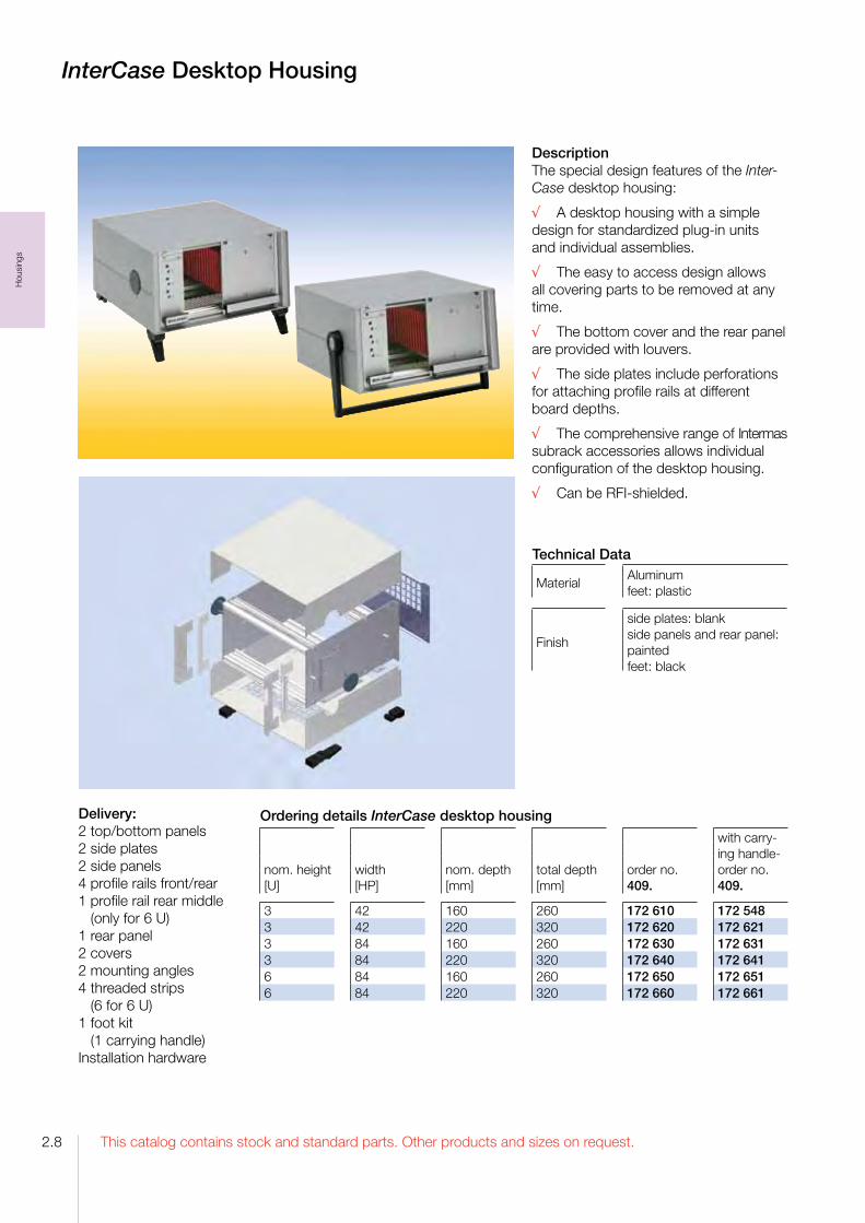
InterCase Desktop Housing
DescriptionThe special design features of the Inter-Case desktop housing:
√ A desktop housing with a simple design for standardized plugin units and individual assemblies.
√ The easy to access design allows all covering parts to be removed at any time.
√ The bottom cover and the rear panel are provided with louvers.
√ The side plates include perforations for attaching profile rails at different board depths.
√ The comprehensive range of Intermas subrack accessories allows individual configuration of the desktop housing.
√ Can be RFIshielded.
Technical Data
MaterialAluminum feet: plastic
Finish
side plates: blankside panels and rear panel:paintedfeet: black
Ordering details InterCase desktop housing
nom. height[U]
width[HP]
nom. depth[mm]
total depth[mm]
order no.409.
with carrying handleorder no.409.
3 42 160 260 172 610 172 5483 42 220 320 172 620 172 6213 84 160 260 172 630 172 6313 84 220 320 172 640 172 6416 84 160 260 172 650 172 6516 84 220 320 172 660 172 661
Delivery:2 top/bottom panels2 side plates2 side panels4 profile rails front/rear1 profile rail rear middle (only for 6 U)1 rear panel2 covers2 mounting angles4 threaded strips (6 for 6 U)1 foot kit (1 carrying handle)Installation hardware

2.9This catalog contains stock and standard parts. Other products and sizes on request.
Hou
sing
s
InterLock Desktop Housing
DescriptionThe InterLock desktop housing has been designed to cover subracks. Also System-Module can be dressed up.
The special design features of the InterLock desktop housing:
√ The covering elements are formed from recyclable polystyrene plate-material warmly and the joints are welded together by means of a chlorine carbon soluti-on coldly.
√ Material strength of 4 to 10 mm can be processed according to demand of the device.
√ Easy assembly or disassembly of the case shells. Both case shells are locked by a clamp groove without screws.
√ The case is upgradeable by feet and handles.
√ However, on account of an economic manufactu-ring technology special dimensions or special colors can be also already realised for small quantities at a reasonable price.
√ Extensive range of accessories is available.
Ordering details kit - InterLock desktop housingnom. height[U]
width[HP]
nom. depth[mm]
order no.409.
3 42 220 168 9353 84 220 168 9366 84 220 168 937
Ordering details for compatible subrack kits
nom. height[HE]
width[HP]
PCB depth/ nom. depth[mm]
order no.409.
Subrack FLEXIBLE Fi-alpha prepared for RFI 3 42 160/220 133 306Subrack FLEXIBLE Fi-alpha prepared for RFI 3 84 160/220 133 307Subrack FLEXIBLE Fi-alpha prepared for RFI 6 84 160/220 133 308
Material: Polystyrene 6 mm thickColor: black
Delivery:The InterLock desktop housing is delivered in single parts.
Set consists of:1 top-shell1 bottom-shell
Accessories InterLockFoot kit: 2 feet without tip-up 2 feet with tip-up 4 lens head screws with nut
Material: UltramidColor: black
Foot kit
order-no.: 409. 133 305
Accessories other housingsFoot kit: 2 feet without tip-up 2 feet with tip-up 4 self-tapping screws
Material: UltramidColor: black
Foot kit
order-no.: 409. 059 640

This catalog contains stock and standard parts. Other products and sizes on request.2.10
Hou
sing
s
DescriptionThe special design features of the DiVar housing:
√ It consists of profiles into which aluminum, sheet steel, stainless steel or plastic panels with a thickness of 1.5 to 2.5 mm are inserted and, if desired, secured with screws. A wall panel at the rear and a panel at the front are screwed to the profiles.
√ The flexible design allows variable configuration of the housing geometry in all three axes, this allowing adaptation of the housing to customerspecific requirements.
√ Different surfaces can be selected for an individual appearance.
√ The proven RFI contact spring concept ensures optimum RFI shielding.
√ Rails with threaded holes can be pressed into the profile grooves, for example to screw in PCBs or mounting plates.
√ The extensive range of Intermas accessories allows unrestricted configuration and installation of both standardized and nonstandard components.
The housing can be supplied in 4 versions:
1. Customized housing2. 19“ rack mounted3. Desktop housing with a keyboard area4. Desktop housing with a continuous slanting surface
DiVar Housing
DiVar housing as individual housing
Painting examples of the DiVar housing
DeliveryThe DiVar housing is delivered unassembled as individual parts or as a kit
Multifunctional Profile DiVar
Material: aluminumFinish: blank
Length: 1000 mm
order no.: 409. 121 808
Accessories
RFI-spring F3Length: 399.64 mm
order no.: 409. 111 774
Technical DataMaterial aluminum
Finishprofiles: blankcover plates, front panel and side plates:front: anodized, rear: conductive

2.11This catalog contains stock and standard parts. Other products and sizes on request.
Hou
sing
s
DiVar Housing as rack mounted version
Delivery4 profiles4 cover plates1 19“ front panel1 rear panelAssembly hardware
DiVar Desktop Housing
Delivery4 profiles4 cover plates2 side platesAssembly hardware
DiVar Desktop Housing with keyboard area
Delivery4 profiles4 cover plates2 side platesAssembly hardware
DiVar Housing
Ordering details DiVar housing as rack mounted versionnom. height [U]
width [HP]
depth[mm]
order no. 409.
1 84 250 122 3562 84 350 122 3573 84 450 122 358
Ordering details DiVar desktop housingheight [mm]
width [mm]
depth[mm]
order no. 409.
50/100 400 250 122 359
Ordering details DiVar desktop housing with keyboard areaheight [mm]
width [mm]
depth[mm]
order no. 409.
50/120 450 250/150 122 360

This catalog contains stock and standard parts. Other products and sizes on request.2.12
Hou
sing
s
Please ask your local representative for your individual configuration.
You find your contact person on our homepage:www.intermas-el.com
DiVar Housing Examples
DiVar housing as covered subrack 3 U - 84 HP - 160 mm depth DiVar housing as covered cassette 3 U - 8 HP - 160 mm depth
DiVar housing for instrumentation

This catalog contains stock and standard parts. Other products and sizes on request.
Sub
rack
s
3.1
Intermas Subracks
Subrack FLEXIBLE
√ Simple and fast assembly√ Allpurpose√ RFI shielding can be added later
Subrack RFI-SHIELDED
√ High shielding effectiveness√ Individual internal layout√ Complies with the latest IEEE standards√ For VME / VME64x
Subrack InterRail®
√ For tough physical demands√ Vibrationproof√ For use e.g. in railway engineering, traffic engineering, power station engineering
System-Modules CompactPCI
√ Integrated bus board√ Integrated power supply unit√ Wired and tested√ Optionally with active cooling

This catalog contains stock and standard parts. Other products and sizes on request.
Sub
rack
s
3.2
Systematics of the Intermas Subracks
��� ��
� ��� ��
� ��� ��
�
���� ��
� ��� ��� ��
�
�����
�����
���� ��
������
���
������
�������
������
������
����
������
�����
��
��������������������� ������������� �����
���
���
����������������
Systematics
The illustration shows the systematics of the height, depth and width pitches of the Intermassubracks.
The height of the subracks are in Units [U].1 U is aquivalent to 44.45 mm.
The nominal depth of the subracks is derived from the euroboard depth. Front inserted PCB’s are generally specified in 60 mmsteps and for rear stucked PCB’s in 20 mmsteps. For Intermas subracks depths in 10 mmsteps can be realized.
The width pitch is stated in horizontal pitches [HP].1 HP is aquivalent to 5.08 mm.
Busboards are specified in slots.1 Slot is aquivalent to 4 HP = 20.32 mm.

This catalog contains stock and standard parts. Other products and sizes on request.
Sub
rack
s
3.3
3. Type delta
The rear profiles are 2.6 mm deeper than in the type alpha, permitting direct mounting of multilayer backplanes and/or connector securing devices for mounting of DINconnectors.
2. Type betaThe rear profiles with integral Zrail are suitable for the direct mounting of connectors to DIN 41 612.
1. Type alpha
The rear profiles are suitable for mounting any appropriate wiring carrier, e. g. bus and connector securing devices, used with insulation strips or Zrails for mounting connectors according to DIN 41 612.
Structual Shapes of Subracks
There are three structural shapes, different in the wiring field.
Intermas Subracks
Please ask your local representative for your individual system configuration.
You can find your contact person at our homepage: www.intermas-el.com

This catalog contains stock and standard parts. Other products and sizes on request.
Sub
rack
s
3.4
DescriptionThe special design features of the subrack FLEXIBLE:
√ For mounting of the profile rails the side wall is perforated with a grid of 10 mm to allow installation of modules in depth steps of 10 mm. This results in a flexible amount of free space behind the wiring level or in front of the operating level.
√ The profile rails are connected to the side wall at the front using a special screw which ensures electrical bonding of the parts via a ring cutter under the head.
√ The front and rear profile rails can be interchanged such that the wiring level which is normally at the rear can be implemented at the front of the subrack.
√ The extensive range of accessories allows individual configuration.
√ Fast and simple assembly:Easy positioning of the profile rails thanks to raised embossing on the side wall.
√ There are 2 versions of this subrack:
1. The FLEXIBLE Fi subrack (with an integrated flange) The combination of the side wall and mounting flange form a single unit. This is the simple and costeffective version. This standard version can not be shielded.
2. The FLEXIBLE Fs subrack (with a separate flange)The side wall and flange are separate components so the flange can be screwed to the side panel at the front or the rear.
Subrack FLEXIBLE
Advantages:• Even if the flange is detached and repositioned from the front to the rear the subrack remains a physical unit and is thus also suitable for direct wall mounting.
• This version can be converted to an RFIshielded subrack with little effort.
Mixed formsFor vertical mounting PCB’s of varying heights, divider kits are available.
DeliverySupplied as unassembled kits. These are either packed as a kit of parts for one unit or as individual components, whereby parts of similar type are packed together.
On request, delivered as assembled and wired subrack according your requirements.

This catalog contains stock and standard parts. Other products and sizes on request.
Sub
rack
s
3.5
Subrack FLEXIBLE
�������� �������� �����
����
�
���
����
�
����������
�����
����
�
����������������� ���������
Front of subrack 6 UFront of subrack 3 U
Dimensions
�������� ��������
����
��
��������
����
��
�����
����
��
����
�
����������
����������������� ���������
Technical dataStandards compliant with DIN 41 494 D IEC 60 297
width / horizontal pitch 84 usable HP / 5.08 mm
Depth of the inserted board 160, 220, 280 mm (nom. depth)
Depth incrementside panel 10 mm
Connector mountingM 2.5 in increments of 5.08 mm for DIN 41 612,VG 95 324 and EC 60 6032 connectors
Materialsscrews: steelother parts: aluminum
Finishscrews: galvanized and chromatedsubrack Fi: colorless anodized; cut areas: blanksubrack Fs: colorless chromated
Protection classDIN 40 050 IP 00, IP 20 with cover panelscontact protection in accordance with VDE 0160
Utilization category 25 °C, +70 °C, 75% relative humidity
Protective groundingall metal parts are electrically bonded to one another following assembly in accordance with VDE 100 D 12.65, § 6 Nb.

This catalog contains stock and standard parts. Other products and sizes on request.
Sub
rack
s
3.6
Subrack FLEXIBLE Fi
Subrack FLEXIBLE Fi
Depth dimensions type alpha 3 U and 6 U
�������� �������� �����
����
�
���
����
�
����������
�����
����
�
����������������� ���������
�������� ��������
����
��
��������
����
��
�����
����
��
����
�
����������
����������������� ���������
�������� ��������
����
��
��������
����
��
�����
����
��
����
�
����������
����������������� ���������
Depth dimensions type beta 3 U and 6 U
�����
����
�
�������������������
�����������
����
�
����������
�����
����
�
���������������
Depth dimensions type delta 3 U and 6 U
�������� �����
����
�
�����������
�����������
����
�
����������
�����
����
�
���������������
���������������� ��������
����
��
����
��
�����
����
��
����
�
����������
����������������� ���������
160220280160
160220280160
160220280160

This catalog contains stock and standard parts. Other products and sizes on request.
Sub
rack
s
3.7
Subrack FLEXIBLE Fi
Ordering details for kits
nom. depth[mm]
typealphaorder no.409.
typebetaorder no.409.
typedeltaorder no.409.
3 U subrackFLEXIBLE Fi 843160 160 087 340 087 440 087 388FLEXIBLE Fi 843220 220 087 341 087 441 087 389FLEXIBLE Fi 843280 280 087 342 087 442 087 3906 U subrackFLEXIBLE Fi 846160 160 087 364 087 446 087 462FLEXIBLE Fi 846220 220 087 365 087 447 087 463FLEXIBLE Fi 846280 280 087 366 087 448 087 464
Accessoriesorder no.409.
Threaded strip 84 x M 2.5 091 255Insulating strip 84 HP 051 981
Kits with 2 cover plate ø 8.5 mm and mounting parts
Cover plates kit slidein 160 162 700Cover plates kit slidein 220 162 701Cover plates kit screwon 160 162 703Cover plates kit screwon 220 162 704Cover plates kit screwon 280 162 705
Further details and possibilities of other applications are in the chapter SubrackAccessories.
Deliverypiecesper kitalpha3 HE
piecesper kitalpha6 HE
piecesper kitbeta3 HE
piecesper kitbeta6 HE
piecesper kitdelta3 HE
piecesper kitdelta6 HE
Side panel Fi, anodized 2 2 2 2 2 2Front profile VE185 2 2 2 2 2 2Rear profile HE185 2 2 Rear profile HZE85 2 2 Rear profile HE285 2 2Center profile ME185 1 Center profile MZE85 1 Center profile ME285 1Mounting parts kit 1 1 1 1 1 1Threaded strip 2 2 2 2 2 2

This catalog contains stock and standard parts. Other products and sizes on request.
Sub
rack
s
3.8
Subrack FLEXIBLE Fs
Subrack FLEXIBLE Fs
Depth dimensions Fs type alpha 3 U and 6 U
Depth dimensions Fs type beta 3 U and 6 U
Depth dimensions Fs type delta 3 U and 6 U
����
��
����� �������� ���
����
��
����������
�����
����
��
����
�
������������� ��������� ������
�����
����� ����� ����������
�����
�����
�����
��� ���
������������������� ���������
����� �������� ���
����
��
������
����������
�����
����
��
����
�
������������
����
��
���������
����� �������� ���
����
��
������
����������
�����
����
��
����
�
�������������
����
��
���������
����
�
����� ����� ����������
����
�
�����
����
�
��� ���
������������������� ���������
����� ����� ����������
����
�
�����
����
�
��� ���
������������������� ���������
����
�
220280220280
220280220280
220280220280

This catalog contains stock and standard parts. Other products and sizes on request.
Sub
rack
s
3.9
Subrack FLEXIBLE Fs
Ordering details for kits
nom. depth[mm]
typealphaorder no.409.
typebetaorder no.409.
typedeltaorder no.409.
3 U subrackFLEXIBLE Fs 843220 220 094 700 094 704 094 708FLEXIBLE Fs 843280 280 094 701 094 705 094 7096 U subrackFLEXIBLE Fs 846220 220 094 702 094 706 094 710FLEXIBLE Fs 846280 280 094 703 094 707 094 711
Deliverypiecesper kitalpha3 U
piecesper kitalpha6 U
piecesper kitbeta3 U
piecesper kitbeta6 U
piecesper kitdelta3 U
piecesper kitdelta6 U
Side panel Fs, chromated 2 2 2 2 2 2Flange separated, anodized 2 2 2 2 2 2Front profile VE1285 2 2 2 2 2 2Rear profile HE185 2 2 Rear profile HZE85 2 2 Rear profile HE285 2 2Center profile ME185 1 Center profile MZE85 1 Center profile ME285 1Mounting parts kit 1 1 1 1 1 1Threaded strip 2 2 2 2 2 2
Accessoriesorder no.409.
Threaded strip 84 x M 2.5 091 255Insulating strip 84 HP 051 981
Kits with 2 cover plates ø 8.5 mm and mounting parts
Cover plates kit screwon 220 162 704Cover plates kit screwon 280 162 705
Further details and possibilities of other applications are in the chapter SubrackAccessories.

This catalog contains stock and standard parts. Other products and sizes on request.
Sub
rack
s
3.10
DescriptionThe system dimensions of the RFISHIELDED subrack are based on those of the FLEXIBLE subrack as a logical further development to produce the perfectly shielded subrack. This allows unrestricted use of the extensive and complete range of accessories.
The special design features of the RFISHIELDED subrack:
√ The refined RFI shielding concept enables high shielding effectiveness.
√ The stable stainless steel contact springs ensure permanent and reliable bonding, even after a large number of plugin cycles.
√ The perforated RFI cover plates guarantee optimal air flow for improved heat dissipation.
√ The use of highquality, seawaterresistant aluminum alloys and stainless steel materials removes, for the most part, the need for unnecessary, environmentally harmful surface treatment.
√ There are three versions of this subrack:
1. Subrack RFISHIELDEDThe standard RFIshielded version.
2. Subrack RFISHIELDED IEEEThe front is in accordance with IEEE 1101.10. The special profile rail is designed for the use of insertion and removal handles (optionally with a hotswap function) for overcoming high insertion and removal resistance.
The card guides are fitted with mechanical coding systems and special bonding for electrostatic discharge.
3. Subrack RFISHIELDED IEEE / Rear I/OThe front and the rear are in accordance with IEEE 1101.10/11. This enables insertion and removal of modules with a front panel from both the front and the rear of the subrack.
Mixed formsFor vertical mounting PCB’s of varying heights, divider kits are available.
DeliverySupplied as unassembled kits. These are either packed as a kit of parts for one unit or as individual components, whereby parts of similar type are packed together.
On request, delivered as assambled and wired subrack according your requirements.
Subrack RFI-SHIELDED

This catalog contains stock and standard parts. Other products and sizes on request.
Sub
rack
s
3.11
Subrack RFI-SHIELDED
Front of subrack 3 U Front of subrack 6 U
�������� ��������
����
��
��������
����
��
�����
����
��
����
�
����������
����������������� ���������
�������� �������� �����
����
�
���
����
�
����������
�����
����
�
����������������� ���������
Dimensions
Technical dataStandards compliant with DIN 41 494 D IEC 60 2973, IEEE 1101.10
Width / horizontal pitch 84 usable HP / 5.08 mm
Depth of the inserted board 160, 220, 280 mm (nom. depth), 80 mm at the rear
Depth incrementside panel 10 mm
Connector mountingM 2.5 in increments of 5.08 mm for DIN 41 612,VG 95 324 and EC 60 6032 connectors
Materialsscrews: steelcontact springs: stainless steelother parts: aluminum
Finishscrews: galvanized und chromatedside panels and cover plates: blank (seawaterresistant) other parts: chromated
Protection classDIN 40 050 IP 00, IP 20 with cover panelscontact protection in accordance with VDE 0160
Utilization category 25 °C, +70 °C, 75% relative humidity
Protective groundingall metal parts are electrically bonded to one anotherfollowing assembly in accordance with VDE 100 D 12.65, § 6 Nb.
This catalog contains stock and standard parts. Other products and sizes on request.
Sub
rack
s
3.12
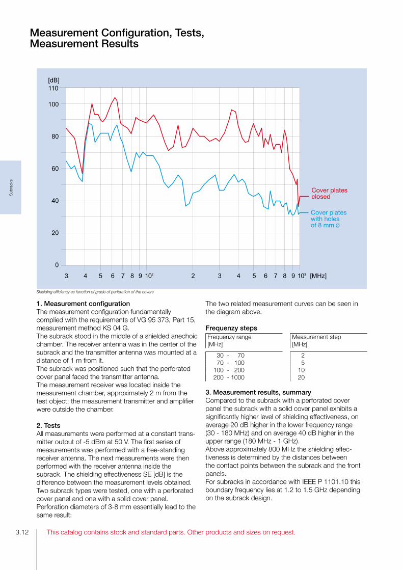
1. Measurement configurationThe measurement configuration fundamentally complied with the requirements of VG 95 373, Part 15, measurement method KS 04 G.The subrack stood in the middle of a shielded anechoic chamber. The receiver antenna was in the center of the subrack and the transmitter antenna was mounted at a distance of 1 m from it.The subrack was positioned such that the perforated cover panel faced the transmitter antenna.The measurement receiver was located inside the measurement chamber, approximately 2 m from the test object; the measurement transmitter and amplifier were outside the chamber.
2. TestsAll measurements were performed at a constant transmitter output of 5 dBm at 50 V. The first series of measurements was performed with a freestanding receiver antenna. The next measurements were then performed with the receiver antenna inside the subrack. The shielding effectiveness SE [dB] is the difference between the measurement levels obtained.Two subrack types were tested, one with a perforated cover panel and one with a solid cover panel. Perforation diameters of 38 mm essentially lead to the same result:
The two related measurement curves can be seen in the diagram above.
Frequenzy stepsFrequenzy range [MHz]
Measurement step[MHz]
30 70 2 70 100 5100 200 10200 1000 20
3. Measurement results, summaryCompared to the subrack with a perforated cover panel the subrack with a solid cover panel exhibits a significantly higher level of shielding effectiveness, on average 20 dB higher in the lower frequency range (30 180 MHz) and on average 40 dB higher in the upper range (180 MHz 1 GHz). Above approximately 800 MHz the shielding effectiveness is determined by the distances between the contact points between the subrack and the front panels. For subracks in accordance with IEEE P 1101.10 this boundary frequency lies at 1.2 to 1.5 GHz depending on the subrack design.
Measurement Configuration, Tests, Measurement Results
Shielding efficiency as function of grade of perforation of the covers

This catalog contains stock and standard parts. Other products and sizes on request.
Sub
rack
s
3.13
Shielding effectiveness
Shielding effectivenessThe shielding effectiveness of the empty subrack was determined in accordance with VG 95 373, Part 15.
Testing organisationThe measurements were performed in the Siemens Institute for Quality Engineering, Testing and Certification in Munich, Germany.
Test objectTwo subracks with a height of 6 U, a width of 84 HP and a depth of 320 mm were tested:
Test specimen 1Subrack 1 was closed at the top and bottom with perforated cover panels (Ø 4/5 x 4 mm), at the rear with an 85 HP front panel and at the front with twentyone 4 HP profile front panels. The elements were bonded to each other via stainless steel RFI gaskets.
Test specimen 2Subrack 2 was closed at the top and bottom with solid cover panels and at the front and the rear with an 85 HP front panel. The elements were bonded to each other via stainless steel RFI gaskets.
Advice on useTo achieve optimal shielding the subrack must be closed at all sides using RFI gaskets, i.e. it must be fitted at the front and the rear with front panels or subassemblies.
Tests, Measurement Results

This catalog contains stock and standard parts. Other products and sizes on request.
Sub
rack
s
3.14
Implementation of the Shielding
The RFISHIELDED subrack is fitted with stainless steel springs on all sides for defined bonding of all individual elements to each other. The only exceptions are the transitions of the cover plates to the side panel. In this case the bonding is performed using multiple screw connections at short distances from one another. The use of RFI front panels with bonding points at the side and bonding areas in the case of the extruded profile front panel results in a shielded subrack with shielding effectiveness levels as shown in the diagram below.
The details of the technical implementation using stainless steel springs:
1. Bonding of the cover panel to the profile channel via the RFI spring A2 which is inserted into the groove of the profile.
2. The RFI spring P2 is snapped onto the profile channel at both the front and the rear and at its front face creates the bonding to the front panels and the rear wall.
3. The RFI spring F3 is used in the subrack flange. This spring is also used at the sides of the RFI front panels and creates the bonding between the front panels and between the front panel and the flange or side panel.
4. The cover panel is screwed directly to the side panel; springs are thus not necessary here.
The subrack, its paneling elements and the cover panels are made of highquality seawaterresistant aluminum alloys. The spring strips are made of stainless steel. This wellbalanced combination of materials and surface treatment ensures high corrosion and ageing resistance and achievement of the necessary low contact resistance between the individual elements.
Sealing of the vertical splices between the front panels and between front panel und flange
Flat front panel Extruded front panel
Side panel
Flange
RFIspring F3
Cover plate,fixed with self tapping screw
RFIspring A2
Bonding with RFIsprings
RFIspring P2
Front panel / Rear panel
This catalog contains stock and standard parts. Other products and sizes on request.
Sub
rack
s
3.15
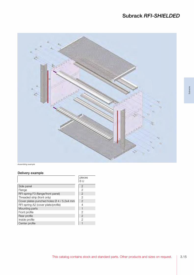
Subrack RFI-SHIELDED
Assembling example
Delivery examplepieces6 U
Side panel 2Flange 2RFIspring F3 (flange/front panel) 2Threaded strip (front only) 2Cover plates punched holes Ø 4 / 5.2x4 mm 2RFIspring A2 (cover plate/profile) 4Mounting parts 1Front profile 2Rear profile 2Inside profile 2Center profile 1

This catalog contains stock and standard parts. Other products and sizes on request.
Sub
rack
s
3.16
Subrack RFI-SHIELDED
Depth dimensions type alpha 3 U and 6 U Depth dimensions type delta 3 U and 6 U
���������� �����
�����
160/220 220/280
���������� �����
�����
160/220 220/280
Ordering details for kits
PCB depth/nom. depth[mm]
type alpha order no. 409.
type delta order no. 409.
3 U subrackRFISHIELDED 843220 160/220 162 708 162 710RFISHIELDED 843280 220/280 162 709 162 7116 U subrackRFISHIELDED 846220 160/220 162 712 162 714RFISHIELDED 846280 220/280 162 713 162 715
Accessoriesorder no. 409.
Threaded strip 84 x M 2.5 091 255Insulating strip 84 HP 051 981RFIspring P2 84 (profile/front panel) 106 547
Further details and possibilities of other applications are in the chapter SubrackAccessories.
Deliverypieces per kitalpha3 U
piecesper kitalpha6 U
piecesper kitdelta3 U
piecesper kitdelta6 U
Side panel 2 2 2 2Flange 2 2 2 2RFIspring F3 (flange/front panel) 2 2 2 2Threaded strip (front only) For your custom subrack please order threaded strips separately. 2 2 2 2
Cover plate punched holes Ø 4 / 5.2 x 4 mm 2 2 2 2RFIspring A2 (cover plate/profile) 4 4 4 4Mounting parts kit 1 1 1 1Front profile/rear V12RFI85 4 4 4 4Inside profileHE185 2 2 Center profile ME185 1 Inside profileHE285 2 2Center profile ME285 1

This catalog contains stock and standard parts. Other products and sizes on request.
Sub
rack
s
3.17
Subrack RFI-SHIELDEDwith Rear Cover
Depth dimensions type delta 3 U and 6 U
����������
160 220
Ordering details for kits
PCB depth[mm]
typedeltaorder no.409.
3 U subrackRFISHIELDED 843160 160 162 716RFISHIELDED 843220 220 162 7176 U subrackRFISHIELDED 846160 160 162 718RFISHIELDED 846220 220 162 719
Accessoriesorder no. 409.
Threaded strip 84 x M 2.5 091 255Insulating strip 84 HP 051 981RFIspring P2 84 (profile/front panel) 106 547
Further details and possibilities of other applications are in the chapter SubrackAccessories.
Deliverypiecesper kitdelta3 U
piecesper kitdelta6 U
Side panel 2 2Flange 2 2Cover 1 1RFIspring F3 (flange/front panel) 2 2Threaded strip (front only) For your custom subrack please order threaded strips separately. 2 2
Cover plates punched holes Ø 4 / 5.2 x 4 mm 2 2RFIspring A2 (cover plate/profile) 4 4Mounting parts kit 1 1Front profile V12RFI85 2 2Rear profile H22RFI85 for screw on cover 2 2Center profile ME285 1

This catalog contains stock and standard parts. Other products and sizes on request.
Sub
rack
s
3.18
Subrack RFI-SHIELDED IEEE
Depth dimensions IEEE type alpha 3 U and 6 U Depth dimensions IEEE type delta 3 U and 6 U
���������� �����
�����
160/220 220/280
���������� �����
�����
160/220 220/280
Ordering details for kits
PCB depth/nom. depth[mm]
type alpha order no. 409.
type delta order no. 409.
3 U subrackRFISHIELDED IEEE 843220 160/220 162 720 162 722RFISHIELDED IEEE 843280 220/280 162 721 162 7236 U subrackRFISHIELDED IEEE 846220 160/220 162 724 162 726RFISHIELDED IEEE 846280 220/280 162 725 162 727
Deliverypieces per kitalpha3 U
piecesper kitalpha6 U
piecesper kitdelta3 U
piecesper kitdelta6 U
Side panel 2 2 2 2Flange 2 2 2 2RFIspring F3 (flange/front panel) 2 2 2 2Threaded strip (front only) For your custom subrack please order threaded strips separately. 2 2 2 2
Cover plates punched holes Ø 4 / 5.2 x 4mm 2 2 2 2RFIspring A2 (cover plate/profile) 4 4 4 4Mounting parts kit 1 1 1 1Front profile/rear V12IEEE85 1 2 1 2Front profile/rear V12RFI85 3 2 3 2Inside profileHE185 2 2 Center profile inside ME185 1 Inside profileHE285 2 2Center profile inside ME285 1
Accessoriesorder no. 409.
Threaded strip 84 x M 2.5 091 255Insulating strip 84 HP 051 981RFIspring P2 84 (profile/front panel) 106 547
Further details and possibilities of other applications are in the chapter SubrackAccessories.

This catalog contains stock and standard parts. Other products and sizes on request.
Sub
rack
s
3.19
Depth dimensions Rear I/O type alpha 3 U and 6 U Depth dimensions Rear I/O type delta 3 U and 6 U
Subrack RFI-SHIELDED Rear I/O
���������� �����
����� ���������� �����
�����
260 260 260 260
Ordering details for kits
nom. depth[mm]
type alpha order no. 409.
type delta order no. 409.
3 U subrackRFISHIELDED Rear I/O843160+80 260 162 728 162 7296 U subrackRFISHIELDED Rear I/O846160+80 260 116 484 161 034
Deliverypieces per kitalpha3 U
piecesper kitalpha6 U
piecesper kitdelta3 U
piecesper kitdelta6 U
Side panel 2 2 2 2Flange 2 2 2 2RFIspring F3 (flange/front panel) 2 2 2 2Threaded strip (front only) For your custom subrack please order threaded strips separately. 2 2 2 2
Cover plates punched holes Ø 4 / 5.2 x 4mm 2 2 2 2RFIspring A2 (cover plate/profile) 4 4 4 4Mounting parts kit 1 1 1 1Front profile V12IEEE85 1 2 1 2Front profile V12RFI85 1 1 Rear profileV1HUCKIEEE85 1 2 1 2Rear profileV1HUCK85 1 1 Inside profileHE185 2 2 Inside profileHE285 2 2Support profile for card guide 2 2 2 2
Accessoriesorder no. 409.
Threaded strip 84 x M 2.5 091 255Insulating strip 84 HP 051 981RFIspring P2 84 (profile/front panel) 106 547
Further details and possibilities of other applications are in the chapter SubrackAccessories.

This catalog contains stock and standard parts. Other products and sizes on request.
Sub
rack
s
3.20
DescriptionThe system dimensions of the InterRail subrack are based on those of the FLEXIBLE Fi as a logical further development to produce a subrack for heavyduty use. This allows unrestricted use of the extensive range of accessories.
The special design features of the InterRail subrack:
√ Profile rails with a high section modulus guarantee resistance to vibrations.
√ The refined RFIshielding concept enables high shielding effectiveness (see the RFISHIELDED chapter).
√ There are four versions of this subrack:
1. Subrack InterRailShielding is not possible for the unsealed version.
2. Subrack InterRail RFIThe RFIshielded version.
3. Subrack InterRail RFI IEEEThe front is in accordance with IEEE 1101.10. The special profile rail is designed for the use of insertion and removal handles (optionally with a hotswap function) for overcoming high insertion and removal resistance. The card guides are fitted with mechanical coding systems and special bonding for electrostatic discharge.
4. Subrack InterRail SNCFThe special subrack with certification from the French Railways.
Mixed formsFor vertical mounting PCB’s of varying heights, divider kits are available.
DeliverySupplied as unassembled kits. These are either packed as a kit of parts for one unit or as individual components, whereby parts of similar type are packed together.
On request, delivered as assembled and wired subrack according your requirements.
Subrack InterRail®

This catalog contains stock and standard parts. Other products and sizes on request.
Sub
rack
s
3.21
Front of subrack 3 U Front of subrack 6 U
Dimensions
�������� ��������
����
��
��������
����
��
�����
����
��
����
�
����������
����������������� ���������
�������� �������� �����
����
�
���
����
�
����������
�����
����
�
����������������� ���������
Subrack InterRail®
Technical data
StandardsIEC 60 297, DIN 41 494, IEEE 1101.10, DIN EN 50 155NF F 60002, NF F 61012, NF F 67012
Width / horizontal pitch 84 usable HP / 5.08 mm ( 36 HP at SNCF)
Depth of the inserted board 160, 220, 280 mm (nom. depth)
Connector mountingM 2.5 in increments of 5.08 mm for connectors, DIN 41 612, VG 95 324 and EC 60 6032
Materialsscrews: steelcontact springs: stainless steel or tinplatedother parts: aluminum
Finishscrews: galvanized und chromated other parts: chromated
Protection classDIN 40 050 IP 20 (with cover plates)contact protection in accordance to VDE 0160
Utilization category 25 °C, +70 °C, 75% relative humidity
Protective groundingall metal parts are electrically bonded to one anotherfollowing assembly in accordance with VDE 100 D 12.65, § 6 Nb.

This catalog contains stock and standard parts. Other products and sizes on request.
Sub
rack
s
3.22
Testing in accordance with DIN EN 50 155The tests are passed if no damage or malfunctions are determined.The tests are performed from 5 to 150 Hz with the assigned accelerations and amplitudes.
Tests in accordance with SNCF NF standardsThe tests are passed if the maximum resonance sharpness of ca. 10 g is not exceeded in any axis.
CertificationBased on development and manufacture certified in accordance with DIN ISO 9001 this SNCFtested subrack complies with the SNCF standards NF F 60002 (testing standard), NF F 61005 (dimensions standard), NF F 67012 (test boards) and DIN EN 50 155. In addition to being certified for railway applications the InterRail subrack is also approved for use with the French National Railways.
Test specimenSubrack with dimensions H = 6 U, W = 84 HP, D = 220 mm
Test sequenceThe following tests were performed in the 3 axes X, Y and Z on the subrack with the PCB configurations listed below:a) Determination of the critical resonance frequencyb) An endurance test at the resonance frequencyThe vibration excitation was performed between 7 and 70 Hz at a constant acceleration of 1 g in 12 cycles each lasting 10 minutes. In total the subrack was vibrated for eight hours,2 hours each with the following alternating board configuration:1. In the Xaxis 21 x 420 g boards2. In the Zaxis 21 x 420 g boards3. In the Yaxis 21 x 240 g boards4. In the Zaxis 4 x 420 g boards plus a 6.22 kg cassette installed in the center.
Subrack InterRail®Tests in accordance with SNCF NF standards and DIN EN 50155
Measurement results with non-stiffened boardsExcerpt from the results of the measurements in the Yaxis, measurement on the front profile rail:Maximum resonancesharpness 10.8 g at 52.5 Hz.Measurement at the rearon the side panel extension: Maximum resonancesharpness 9.6 g at 52.5Hz(see the measurement curve).
Measurement results with stiffened boardsThese measurements are not demanded by the testing standard but were nonetheless also performed.Excerpt from the results of the measurement in the Yaxis, measured on the front profile rail:Maximum resonance sharpness 7.6 g at 47.1 Hz.
Measurement at the rear on the side panel extension:Maximum resonance sharpness 6.5 g at 47.1 Hz.
Test result Following vibration for a total of 8 hours the test specimen showed no signs of damage.

This catalog contains stock and standard parts. Other products and sizes on request.
Sub
rack
s
3.23
Subrack InterRail®
Delivery examplepieces6 U
Side panel 2Cover 1Threaded strip (front only) 2Cover plates punched holes Ø 4 / 5.2x4 mm 2RFIspring A2 (cover plate/profile) 4Mounting parts 1Front profile 2Rear profile 2Inside profile 2Center profile 1

This catalog contains stock and standard parts. Other products and sizes on request.
Sub
rack
s
3.24
����� ����� �����
Depth dimensions type alpha 3 U and 6 U
Subrack InterRail®
160 220 280220
Ordering details for kits
nom. depth[mm]
typealphaorder no.409.
3 U subrackInterRail 843160 160 162 610InterRail 843220 220 162 611InterRail 843280 280 162 6126 U subrackInterRail 846160 160 162 613InterRail 846220 220 162 614
Deliverypiecesper kitalpha3 U
piecesper kitalpha6 U
Side panel 2 2Threaded strip (front only) For your custom subrack please order threaded strips separately. 2 2
Mounting parts kit 1 1Front profile V12SRFI85 2 2Rear profile H12S85 2 2Center profile M1S85 1
Accessoriesorder no.409.
Threaded strip 84 x M 2.5 091 255Insulating strip 84 HP 051 981
Further details and possibilities of other applications are in the chapter SubrackAccessories.

This catalog contains stock and standard parts. Other products and sizes on request.
Sub
rack
s
3.25
Subrack InterRail® RFI
Depth dimensions type delta 3 U and 6 U
����������
160/220 220/280
Ordering details for kits
PCB depth/nom. depth[mm]
typedeltaorder no.409.
3 U subrackInterRail RFI843220 160/220 162 730InterRail RFI843280 220/280 162 7316 U subrackInterRail RFI 846220 160/220 162 732InterRail RFI 846280 220/280 162 733
Deliverypiecesper kitdelta3 U
piecesper kitdelta6 U
Side panel with flange 2 2Threaded strip (front only) For your custom subrack please order threaded strips separately. 2 2
Cover plates punched holes Ø 4 / 5.2 x 4mm 2 2RFIspring A2 (cover plate/profile) 4 4Mounting parts kit 1 1Front profile V12SRFI85 2 2Rear profile H22SRFI85 2 2Center profile M2S85 1
Accessoriesorder no.409.
Threaded strip 84 x M 2.5 091 255RFIspring P2 84 (profile/front panel) 106 547Shielding kit F1 3 U (side panel/front panel) 093 605Shielding kit F1 6 U (side panel/front panel) 093 606Shielding kit 3 U (side panel/backplane) 108 274Shielding kit 6 U (side panel/backplane) 108 275
Further details and possibilities of other applications are in the chapter SubrackAccessories.

This catalog contains stock and standard parts. Other products and sizes on request.
Sub
rack
s
3.26
Subrack InterRail® RFIwith Rear Cover or for Front Panel in the Rear
Depth dimensions type delta 3 U and 6 U with cover Depth dimensions type alpha 3 U and 6 U for front panel
����������
160220
����������
160/220 160/220
Deliverypieces per kitalpha3 U
piecesper kitalpha6 U
piecesper kitdelta3 U
piecesper kitdelta6 U
Side panel with flange 2 2 2 2Threaded strip (front only) For your custom subrack please order threaded strips separately. 2 2 2 2
Cover plates punched holes Ø 4 / 5.2 x 4mm 2 2 2 2RFIspring A2 (cover plate/profile) 4 4 4 4Mounting parts kit 1 1 1 1Cover 1 1 Front profile/rear V12S85 2 2 4 4Rear profile H22RFI85 screw on cover 2 2 Center profile M2S85 1 Rear profile H12S85 2 2Center profile M1S85 1
Ordering details for kits
nom. depth[mm]
typedeltawith coverorder no.409.
f. front panel
PCB depth/nom. depth[mm]
typealphaf. front panelorder no.409.
3 U subrackInterRail RFI 843160 160 162 734 -InterRail RFI 843220 220 162 735 160/220 162 7386 U subrackInterRail RFI 846160 160 162 736 -InterRail RFI 846220 220 162 737 160/220 162 739
Accessoriesorder no.409.
Threaded strip 84 x M 2.5 091 255Insulating strip 84 HP 051 981RFIspring P2 84 (profile/front panel) 106 547Shielding kit F1 3 U (side panel/front panel) 093 605Shielding kit F1 6 U (side panel/front panel) 093 606
Further details and possibilities of other applications are in the chapter SubrackAccessories.

This catalog contains stock and standard parts. Other products and sizes on request.
Sub
rack
s
3.27
Subrack InterRail® RFI-IEEE
Depth dimensions IEEE type delta 3 U and 6 U with cover Depth dimensions IEEE type alpha 3 U and 6 U for front panel
����������
160/220 160/220
����������
160220
Deliverypieces per kitwith cover3 U
piecesper kitwith cover6 U
piecesper kitf. front panel3 U
piecesper kitf. front panel6 U
Side panel with flange 2 2 2 2Threaded strip (front only) For your custom subrack please order threaded strips separately. 2 2 2 2
Cover plates punched holes Ø 4 / 5.2 x 4mm 2 2 2 2RFIspring A2 (cover plate/profile) 4 4 4 4Mounting parts kit 1 1 1 1Cover 1 1 Front profile V12IEEE85 1 2 1 2Front profile/rear V12S85 1 3 2Rear profile H22RFI f. Cover 85 2 2 Center profile M2S85 1 Inside profile H12S85 2 2Center profile inside M1S85 1
Ordering details for kits
nom. depth[mm]
typedeltawith coverorder no.409.
f. front panel
PCB depth/nom. depth[mm]
typealphaf. front panelorder no.409.
3 U subrackInterRail RFI 843160 160 162 740 -InterRail RFI 843220 220 162 741 160/220 162 7446 U subrackInterRail RFI 846160 160 162 742 -InterRail RFI 846220 220 162 743 160/220 162 745
Accessoriesorder no.409.
Threaded strip 84 x M 2.5 091 255Insulating strip 84 HP 051 981RFIspring P2 84 (profile/front panel) 106 547Shielding kit F1 3 U (side panel/front panel) 093 605Shielding kit F1 6 U (side panel/front panel) 093 606
Further details and possibilities of other applications are in the chapter SubrackAccessories.
This catalog contains stock and standard parts. Other products and sizes on request.
Sub
rack
s
3.28
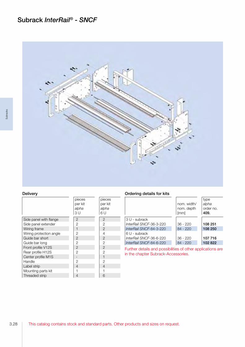
Subrack InterRail® - SNCF
Ordering details for kits
nom. width/nom. depth[mm]
typealphaorder no.409.
3 U subrackInterRail SNCF363220 36 220 108 251InterRail SNCF843220 84 220 108 2506 U subrackInterRail SNCF366220 36 220 107 716InterRail SNCF846220 84 220 102 822
Further details and possibilities of other applications are in the chapter SubrackAccessories.
Deliverypieces per kit alpha 3 U
pieces per kit alpha 6 U
Side panel with flange 2 2Side panel extender 2 2Wiring frame 1 2Wiring protection angle 2 4Guide bar short 2 2Guide bar long 2 2Front profile V12S 2 2Rear profile H12S 2 2Center profile M1S 1Handle 2 2Label strip 4 4Mounting parts kit 1 1Threaded strip 4 6

This catalog contains stock and standard parts. Other products and sizes on request.
Sub
rack
s
3.29
Ordering details for kits
nom. width/nom. depth[mm]
typedeltaorder no.409.
3 U subrackInterRail SNCF RFI363220 36 220 108 255InterRail SNCF RFI843220 84 220 108 2546 U subrackInterRail SNCF RFI366220 36 220 108 253InterRail SNCF RFI846220 84 220 108 252
Deliverypieces per kit delta 3 U
pieces per kit delta 6 U
Side panel with flange 2 2Side panel extender 2 2Wiring frame 1 2Wiring protection angle 2 4Guide bar short 2 2Guide bar long 2 2Front profile V12S 2 2Rear profile H22S 2 2Center profile M2S 1Cover plates with punched holes Ø 8 mm
2 2
RFIspringn A2 (cover plates/profile)
4 4
Handle 2 2Label strip 4 4Mounting parts kit 1 1Threaded strip 4 6
Accessoriesorder no.409.
Card guide VIB 1.6220 without nut 058 944Screw M 3.2 x 12 for card guide SNCF 102 432RFIspring P2 84 (profile/front panel) 106 547Shielding kit F1 3 U (side panel/front panel) 093 605Shielding kit F1 6 U (side panel/front panel) 093 606
Further details and possibilities of other applications are in the chapter SubrackAccessories.
Subrack InterRail® - SNCF RFI

This catalog contains stock and standard parts. Other products and sizes on request.
Sub
rack
s
3.30
System-Module CompactPCI
DescriptionThe special design features of the CompactPCI system modules:
√ The refined RFIshielding concept enables high shielding effectiveness (see the RFISHIELDED chapter).
√ The construction offers additional space for drives and hard disks.
√ They are fitted with an ATX 300 W power supply unit with a widerange input and PFC.
√ CPCI backplane in accordance with specification 2.0 Rev. 3.0, with or without rear I/O
√ Convection or active ventilation
DeliveryThe subrack is delivered assembled.
Other systems on request.
Technical data
Standardscompliant with DIN 41 494, IEC 60 2973, IEEE 1101.10IEC 61 0764101, CPCI Specification 2.0, Revision 3.0
Width / horizontal pitch 84 usable HP/ 5.08 mm
Depth of the inserted board 160 mm at the front, 80 mm at the rear
Depth increment side panel 10 mm
Materials
screws: steelcontact springs: stainless steel card guide: plasticother parts: aluminum
Finishscrews: galvanized und chromated side panels and cover plates: blank (seawater resistance)other parts: chromated
Protection classDIN 40 050 IP 20 (with cover plates)contact protection in accordance with VDE 0160
Utilization category 25 °C, +70 °C, 75% relative humidity
Protective groundingall metal parts are electrically bonded to one anotherfollowing assembly in accordance with VDE 100 D 12.65, § 6 Nb.

This catalog contains stock and standard parts. Other products and sizes on request.
Sub
rack
s
3.31
System-Module CompactPCI
Consists of:1 Subrack RFISHIELDED CPCI / REAR I/O 84 HP, 260 mm nom. depth (160 mm at the front, 80 mm at the rear)1 Backplane 8 Slot, 3 U, 32 Bit, system slot right1 ATX 300W power supply unit with a widerange input and PFC, with assembled front panel.1 Blind front panel 16 HP at the front.1 Blind front panel 4 HP at the front.1 Blind front panel 48 HP at the rear.1 Blind front panel 8 HP at the rear.1 Pair of card guides red 160 mm (CPU) including IEEEcoding and ESDspring in the bottom card guide.1 Pair of card guides red 80 mm (CPU) including IEEEcoding and 7 Pair of card guides black 160 mm (CPU) including IEEEcoding and ESDspring in the bottom card guide.7 Pair of card guides black 80 mm (CPU) including IEEEcoding and ESDspring in the bottom card guide.

This catalog contains stock and standard parts. Other products and sizes on request.
Sub
rack
s
3.32
System-Module CompactPCI- 3 U-Rear I/O and 6 U-Rear I/O
System-Module CompactPCI-6 U-Rear I/O
order no.: 409. 122 297
Consists of:1 Subrack RFISHIELDED CPCI / REAR I/O 84 HP, 260 mm nom. depth (160 mm at the front, 80 mm at the rear)1 Backplane 8 Slot, 6 U, 64 Bit, system slot right1 ATX 300W power supply unit with a widerange input and PFC, with assembled front panel. (optional front panel for a drive over the power supply).1 Blind front panel 16 HP at the front.1 Blind front panel 4 HP at the front.1 Blind front panel 48 HP at the rear.1 Blind front panel 8 HP at the rear.1 Pair of card guides red 160 mm (CPU) including IEEEcoding and ESDspring in the bottom card guide.1 Pair of card guides red 80 mm (CPU) including IEEEcoding and ESDspring in the bottom card guide.7 Pair of card guides black 160 mm (CPU) including IEEEcoding and ESDspring in the bottom card guide.7 Pair of card guides black 80 mm (CPU) including IEEEcoding and ESDspring in the bottom card guide.
System-Module CompactPCI-3 U-Rear I/O
order no.: 409. 122 295
Consists of:1 Subrack RFISHIELDED CPCI / REAR I/O 84 HP, 260 mm nom. depth (160 mm at the front, 80 mm at the rear)1 Backplane 8 Slot, 3 U, 32 Bit, system slot right1 ATX 300W power supply unit with a widerange input and PFC, with assembled front panel.1 Blind front panel 16 HP at the front.1 Blind front panel 4 HP at the front.1 Blind front panel 48 HP at the rear.1 Blind front panel 8 HP at the rear.1 Pair of card guides red 160 mm (CPU) including IEEEcoding and ESDspring in the bottom card guide.1 Pair of card guides red 160 mm (CPU) including IEEEcoding and ESDspring in the bottom card guide.7 Pair of card guides black 160 mm (CPU) including IEEEcoding and ESDspring in the bottom card guide.7 Pair of card guides black 80 mm (CPU) including IEEEcoding and ESDspring in the bottom card guide.

This catalog contains stock and standard parts. Other products and sizes on request.
Sub
rack
s
3.33
System-Module CompactPCI -6+3 U-Rear I/O and 4 U-Rear I/O
System-Module CompactPCI-4 U-Rear I/O
order no.: 409. 122 300
Consists of:1 subrack RFISHIELDED CPCI / REAR I/O 84 HP, 260 mm nom. depth (160 mm at the front, 80 mm at the rear) for horizontal embedded 6 U PCB’s1 Backplane 4 Slot, 6 U, 64 Bit, system slot right (1 Slot free e. g. for hard disk or driver)2 Front panels 6 U 4 HP (1 at the front, 1 at the rear)1 ATX 300 W power supply unit with a widerange input and PFC, with integrated 32 HP Front panel at the front.1 Fan1 Pair of card guides red 160 mm (CPU) including IEEEcoding and ESDspring in the bottom card guide.1 Pair of card guides red 80 mm (CPU) including IEEEcoding and ESDspring in the bottom card guide.4 Pair of card guides black 160 mm (CPU) including IEEEcoding and ESDspring in the bottom card guide.4 Pair of card guides black 80 mm (CPU) including IEEEcoding and ESDspring in the bottom card guide.
System-Module CompactPCI-6 +1U-Rear I/O
order no.: 409. 122 301
Consists of:1 subrack RFISHIELDED CPCI / REAR I/O 84 HP, 260 mm nom. depth (160 mm at the front, 80 mm at the rear)1 Backplane 8 Slot, 6 U, 64 Bit, system slot right1 ATX 300W power supply unit with a widerange input and PFC, with assembled front panel. (optional front panel for a drive over the power supply).1 Blind front panel 16 HP at the front.1 Blind front panel 4 HP at the front.1 Blind front panel 48 HP at the rear.1 Blind front panel 8 HP at the rear.1 Fan drawer with integrated fan.1 Pair of card guides red 160 mm (CPU) including IEEEcoding and ESDspring in the bottom card guide.1 Pair of card guides red 80 mm (CPU) including IEEEcoding and ESDspring in the bottom card guide.7 Pair of card guides black 160 mm (CPU) including IEEEcoding and ESDspring in the bottom card guide.7 Pair of card guides black 80 mm (CPU) including IEEEcoding and ESDspring in the bottom card guide.

This catalog contains stock and standard parts. Other products and sizes on request.
Sub
rack
s
3.34
System-ModuleConfiguration
Please ask your local representative for yourindividual system-module-configuration.
You find your contact person on our homepage: www.intermas-el.com
Configuration System-Module CompactPCI
Housing Subrack
pieces ________pieces ________
Dimensionsheight: 3 U 6 U other _____ Uwidth: 84 HP 42 HP other _____ HPdepth: 260 mm other _____ mm
Backplane
CPU number of slots ________
J1 VME number of slots ________
J1/J2 Monilithic VME number of slots ________
VME64x number of slots ________Rear I/O: 80 mm other _____ mm
CPCI number of slots ________System slot: right left Width system slot: 4 HP 8 HP Rear I/O : 80 mm other _____ mm
Mounting position PCB horizontal vertical
Depth of the PCB 160 mm other_____ mm
Power supply / PSU
AC / DC DC / DC ATX 300 Watt 400 Watt 19“ 300 Watt 400 Watt other Watt ________ active ventilation of the system
Accessories Harddisc CDROM Keypad
Notes
______________________________________________________________________________
______________________________________________________________________________
______________________________________________________________________________
______________________________________________________________________________
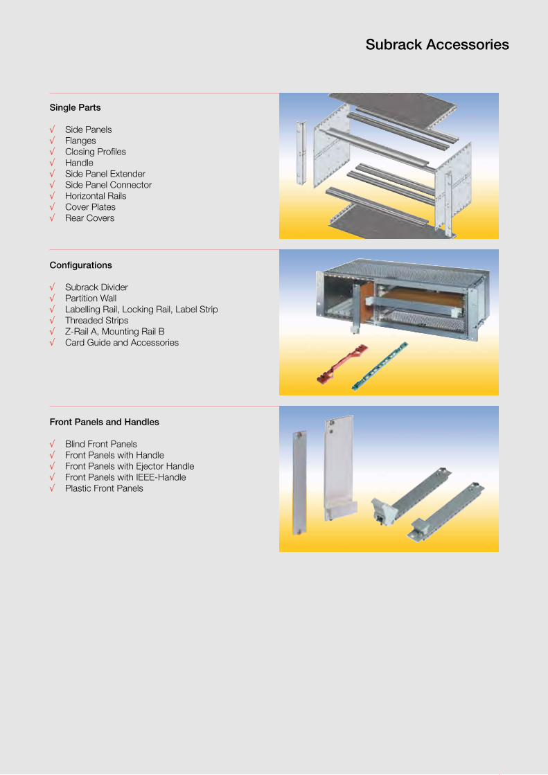
3.35This catalog contains stock and standard parts. Other products and sizes on request.
Sub
rack
Acc
esso
ries
Subrack Accessories
Single Parts
√ Side Panels√ Flanges√ Closing Profiles√ Handle√ Side Panel Extender√ Side Panel Connector√ Horizontal Rails√ Cover Plates√ Rear Covers
Configurations
√ Subrack Divider√ Partition Wall√ Labelling Rail, Locking Rail, Label Strip√ Threaded Strips√ ZRail A, Mounting Rail B√ Card Guide and Accessories
Front Panels and Handles
√ Blind Front Panels√ Front Panels with Handle√ Front Panels with Ejector Handle√ Front Panels with IEEEHandle√ Plastic Front Panels

This catalog contains stock and standard parts. Other products and sizes on request.3.36
Sub
rack
Acc
esso
ries
Side Panel Fi
for subrack FLEXIBLE Fi and InterRail (not for InterRail SNCF)
Side Panel Fi (flange integrated)The side panel and the flange are extruded in one piece.
Material: aluminum, extrudedFinish: colorless anodized or colorless chromated
Accessories
Hexagonal cupped point head screw M 4 x 16, Torx T 20For assembly of the side panel to the horizontal rails.Minimumm order quantity 100 pieces
order no.: 409. 052 156
����
��
���
���
����
�
�����
����
����
����
����
�
����
�
Self tapping hexagonal cupped point head screw M 4 x 16, Torx T 20For assembly of the side panel to the horizontal rails for subrack InterRail.Minimumm order quantity 100 pieces
order no.: 409. 078 693
Ordering details
nom. height [U]
nom. depth [mm]
depth [mm]
anodized order no. 409.
chromated order no. 409.
Side panel Fi 3 160 3 160 175.4 085 001 110 248Side panel Fi 3 220 3 220 235.4 085 002 110 234Side panel Fi 3 280 3 280 295.4 085 003 110 249Side panel Fi 6 160 6 160 175.4 085 095 110 201Side panel Fi 6 220 6 220 235.4 085 096 110 238Side panel Fi 6 280 6 280 295.4 085 097 110 202

3.37This catalog contains stock and standard parts. Other products and sizes on request.
Sub
rack
Acc
esso
ries
Side Panel Fs
for subrack FLEXIBLE Fs
Side Panel Fs (flange separate)
Material: aluminum, extrudedFinish: colorless chromated
Accessories
Hexagonal cupped point head screw M 4 x 16, Torx T 20For assembly of the side panel to the horizontal rails.
Minimumm order quantity 100 pieces
order no.: 409. 052 156
����
�
���
����
�
�����
����
����
����
����
��
����
�
30863326086335
Ordering detailsnom. height [U]
nom. depth [mm]
depth [mm]
order no. 409.
Side panel Fs 3 160 3 160 174.2 106 750Side panel Fs 3 220 3 220 234.2 086 333Side panel Fs 3 280 3 280 294.2 086 334Side panel Fs 6 160 6 160 174.2 097 286Side panel Fs 6 220 6 220 234.2 086 336Side panel Fs 6 280 6 280 294.2 086 337
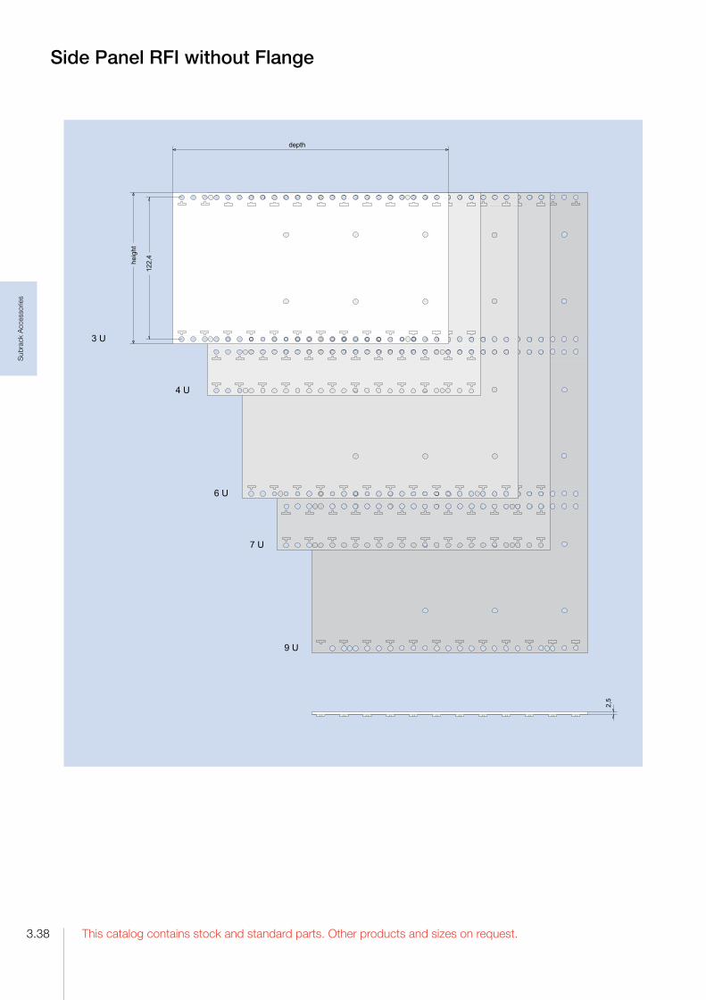
This catalog contains stock and standard parts. Other products and sizes on request.3.38
Sub
rack
Acc
esso
ries
Side Panel RFI without Flange
�����
���
������
����
�
���
���
���
���
���
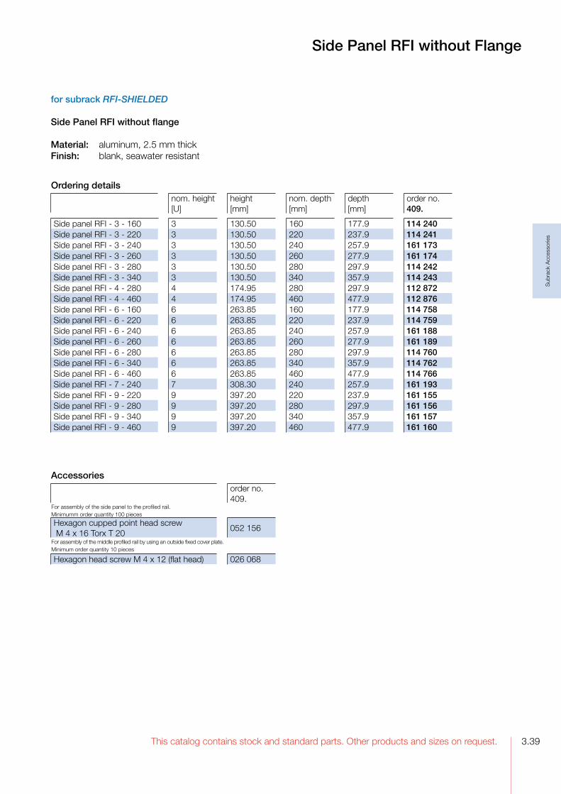
3.39This catalog contains stock and standard parts. Other products and sizes on request.
Sub
rack
Acc
esso
ries
for subrack RFI-SHIELDED
Side Panel RFI without flange
Material: aluminum, 2.5 mm thickFinish: blank, seawater resistant
Side Panel RFI without Flange
Ordering detailsnom. height [U]
height [mm]
nom. depth [mm]
depth [mm]
order no. 409.
Side panel RFI 3 160 3 130.50 160 177.9 114 240Side panel RFI 3 220 3 130.50 220 237.9 114 241Side panel RFI 3 240 3 130.50 240 257.9 161 173Side panel RFI 3 260 3 130.50 260 277.9 161 174Side panel RFI 3 280 3 130.50 280 297.9 114 242Side panel RFI 3 340 3 130.50 340 357.9 114 243Side panel RFI 4 280 4 174.95 280 297.9 112 872Side panel RFI 4 460 4 174.95 460 477.9 112 876Side panel RFI 6 160 6 263.85 160 177.9 114 758Side panel RFI 6 220 6 263.85 220 237.9 114 759Side panel RFI 6 240 6 263.85 240 257.9 161 188Side panel RFI 6 260 6 263.85 260 277.9 161 189Side panel RFI 6 280 6 263.85 280 297.9 114 760Side panel RFI 6 340 6 263.85 340 357.9 114 762Side panel RFI 6 460 6 263.85 460 477.9 114 766Side panel RFI 7 240 7 308.30 240 257.9 161 193Side panel RFI 9 220 9 397.20 220 237.9 161 155Side panel RFI 9 280 9 397.20 280 297.9 161 156Side panel RFI 9 340 9 397.20 340 357.9 161 157Side panel RFI 9 460 9 397.20 460 477.9 161 160
Accessoriesorder no.409.
For assembly of the side panel to the profiled rail. Minimumm order quantity 100 pieces
Hexagon cupped point head screw M 4 x 16 Torx T 20
052 156
For assembly of the middle profiled rail by using an outside fixed cover plate.Minimum order quantity 10 pieces
Hexagon head screw M 4 x 12 (flat head) 026 068

This catalog contains stock and standard parts. Other products and sizes on request.3.40
Sub
rack
Acc
esso
ries
for subrack InterRail SNCF
Side Panel InterRail SNCF
Material: aluminum, extrudedFinish: colorless chromated
31077186105601
Side Panel InterRail® SNCF
Accessories
Self tapping hexagonal cupped point head screw M 4 x 16, Torx T 20For assembly of the side panel to the horizontal rails.
Minimumm order quantity 100 pieces
order no.: 409. 087 639
�����
������
���
�����
����
�
���
����
��
����
�
����
�
Ordering detailsnom. height [U]
nom. depth [mm]
depth [mm]
order no. 409.
Side panel InterRail SNCF 3 220 3 220 237.9 107 719Side panel InterRail SNCF 6 220 6 220 237.9 105 602

3.41This catalog contains stock and standard parts. Other products and sizes on request.
Sub
rack
Acc
esso
ries
for subrack FLEXIBLE Fs
Flange FThe flange can be mounted to the side panel by means of the mounting screws for the horizontal rails.
Material: aluminum, extrudedFinish: anodized
Flange FFlange without Nose
����
��
�������������
�����
����
�
Flange without NoseThis flange can be mounted at various depth on the side panel grid.
Material: aluminum, extrudedFinish: anodized
����
�
����
�
�������������
����
����
��
�������������
����
�
����
����
�
����
�
�������������
Ordering detailsorder no. 409.
Flange F 3 U 086 787Flange F 6 U 086 791
Ordering detailsorder no. 409.
Flange without nose 3 U 087 802Flange without nose 6 U 087 824

This catalog contains stock and standard parts. Other products and sizes on request.3.42
Sub
rack
Acc
esso
ries
for subrack RFI-SHIELDED
Flange RFIThe flange can be mounted to the side panel by means of the mounting screws for the horizontal rails.With slits in the side edges for insertion of RFI springs.
Material: aluminum, extrudedFinish: colorless chromated
�����������
�����
����
�
����
�
���
�����������
�����
����
������
�
����
�
���
������������
�����
����
��
���
������������
�����
����
�
����
���
���
����
��
���
������������
�����
����
�
����
���
���
����
�
���
Flange RFI
Ordering detailsnom. height [U]
order no. 409.
Flange RFI 3 3 112 202Flange RFI 4 4 114 612Flange RFI 6 6 112 205Flange RFI 7 7 114 618Flange RFI 9 9 112 234
Accessories
order no.409.
RFIspring F3 2 U 112 386RFIspring F3 3 U 111 636RFIspring F3 4 U 112 387RFIspring F3 6 U 111 637

3.43This catalog contains stock and standard parts. Other products and sizes on request.
Sub
rack
Acc
esso
ries
Flange RFI - FPThis flange is suitable for mounting of a continous front panel of 85 HP and a hinged front panel of 85 HP in a subrack. The flange will be mounted to the side panelby means of the mounting screws for the horizontal rails.
Material: aluminum, extrudedFinish: colorless chromated
Flange RFI - FP,Flange for Wall Mounting
Flange for Wall MountingFor mounting of a subrack on a wall.
Material: aluminumFinish: blank, seawater resistant
����
��
�������������
����
�
����
���
����
�
�������������
�����
���
����
�
����
�
�������������
����
��
�������������
����
����
�
Ordering details
order no.409.
Flange RFI FP 3 U 114 708Flange RFI FP 6 U 114 715
Ordering details
order no.409.
Flange for wall mounting 3 U 161 110Flange for wall mounting 6 U 161 113

This catalog contains stock and standard parts. Other products and sizes on request.3.44
Sub
rack
Acc
esso
ries
Screw retrainer M6Color: blackMaterial: POMMinimum order quantity 10 pieces
order no.: 409. 074 387
Closing Profile FFor covering the slit between front panel and side panel.The closing profile will be mounted to the side panel by means of the mounting screws for the horizontal rails.
Material: aluminum, extrudedFinish: anodized
Closing Profile RFI - F3For covering the slit between front panel and side panel.The closing profile will be mounted to the side panel by means of the mounting screws for the horizontal rails. With slits for insertion of RFIsprings.
Material: aluminum, extrudedFinish: colorless chromated
Handle
Material: aluminumFinish: anodized
Oval head screwM6 x 16 DIN 7985steel, nickel platedMinimum order quantity 10 pieces
order no.: 409. 013 919
Mounting parts for fastening a subrack into a housing
AccessoriesCounter sunk screw M4 x 10, TorxMinimumm order quantity 100 pieces
order no.: 409. 105 789
Closing Profiles F and RFI - F3,Handle
����
�
����
�
����
����
���
����
��
����
�
����
�
����
�
����
�
����
��
Ordering detailsorder no. 409.
Closing profile F 3 U 085 695Closing profile F 6 U 085 696
Ordering detailsorder no. 409.
Closing profile RFI F3 3 U 122 131Closing profile RFI F3 6 U 118 374
Accessoriesorder no. 409.
RFIspring F3 3 U 111 636RFIspring F3 6 U 111 637
Ordering detailsorder no. 409.
Handle 3 U 040 419Handle 6 U 040 420

3.45This catalog contains stock and standard parts. Other products and sizes on request.
Sub
rack
Acc
esso
ries
Side Panel ConnectorJoin two subracks, one above the other.The side panel connector is mounted to the side panels by means of the mounting screws for the horizontal rails. (nom. depth 160 mm).
Material: aluminum, 2 mm thickFinish: blank
order no.: 409. 065 819
Side Panel ExtenderElongate a side panel about 60 mm to obtain a larger cabling space.The side panel extender is mounted to the side panel by means of the mounting screws for the horizontal rails.
Material: aluminum, 2 mm thickFinish: colorless chromated
�����
����
����
����
����
����
���
����
��
����
�
����
�
��
Side Panel Extender,Side Panel Connector
Ordering detailsorder no. 409.
Side panel extender 3 U 087 820Side panel extender 6 U 087 821
065 818

This catalog contains stock and standard parts. Other products and sizes on request.3.46
Sub
rack
Acc
esso
ries
Horizontal Rails
����
��
��
����
�
���������������� �
��������
for subrack FLEXIBLE Fi
Front Profile VE1(also rear profile by using of a front panel on the rear).
Material: aluminumFinish: anodized
for subrack FLEXIBLE
Front Profile VE12With 2 tapped holes.
Material: aluminumFinish: colorless chromated��
�����������������
��������
��
���
� ��
���
�
��
for subrack FLEXIBLE, RFI-SHIELDED and InterRail
Front Profile 2xVE1For partition e. g. 6 U subracks into two fields of 3 U.
Material: aluminumFinish: colorless chromated
079503
061543
053303
����
��
��
�����������������
��������
Ordering detailsnom. width [HP]
length [mm]
order no. 409.
Front profile VE1 21 106.68 079 521Front profile VE1 43 218.44 079 543Front profile VE1 85 431.80 079 585
Ordering detailsnom. width [HP]
length [mm]
order no. 409.
Front profile 2xVE1 21 106.68 053 321Front profile 2xVE1 29 147.32 053 329Front profile 2xVE1 43 218.44 053 343Front profile 2xVE1 85 431.80 053 385
Ordering detailsnom. width [HP]
length [mm]
order no. 409.
Front profile VE12 43 218.44 062 043Front profile VE12 85 431.80 062 085

3.47This catalog contains stock and standard parts. Other products and sizes on request.
Sub
rack
Acc
esso
ries
Horizontal Rails
for subrack RFI-SHIELDED and InterRail
Front Profile V12-IEEEWith grid holes for IEEE handle.
Material: aluminumFinish: colorless chromated
for subrack RFI-SHIELDED
Front Profile V12-SFP-RFIFor adapting a plug in front panel.
Material: aluminumFinish: colorless chromated
for subrack RFI-SHIELDED
Front Profile V12-RFI(also rear profile by using a front panel on the rear).With retainer for RFIspring A2
Material: aluminumFinish: colorless chromated
109933
088361
��
�����������������
��������
��
���
�
�
��
�����������������
�
��
����
��
��������
���������������������
��
����
��
����
114561
Ordering detailsnom. width [HP]
length [mm]
order no. 409.
Front profile V12RFI 43 218.44 090 799Front profile V12RFI 85 431.80 088 365
Ordering detailsnom. width [HP]
length [mm]
order no. 409.
Front profile V12SFPRFI 85 431.80 114 562
Ordering detailsnom. width [HP]
length [mm]
order no. 409.
Front profile V12IEEERFI 43 218.44 111 182Front profile V12IEEERFI 85 431.80 109 934
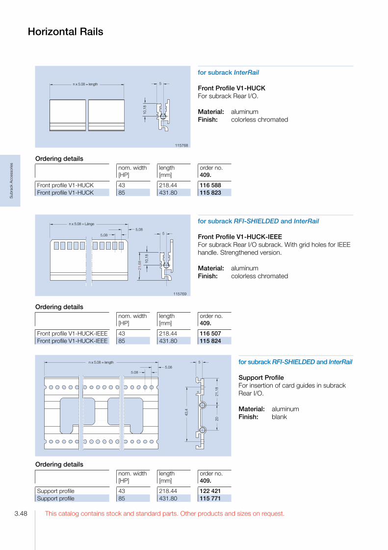
This catalog contains stock and standard parts. Other products and sizes on request.3.48
Sub
rack
Acc
esso
ries
Horizontal Rails
for subrack RFI-SHIELDED and InterRail
Front Profile V1-HUCK-IEEEFor subrack Rear I/O subrack. With grid holes for IEEE handle. Strengthened version.
Material: aluminumFinish: colorless chromated
for subrack InterRail
Front Profile V1-HUCKFor subrack Rear I/O.
Material: aluminumFinish: colorless chromated
for subrack RFI-SHIELDED and InterRail
Support ProfileFor insertion of card guides in subrack Rear I/O.
Material: aluminumFinish: blank
115769
115768
�����������������
����
�
�
����������������
�
����
� ����
�
����
����
����
����
�
������������������
��������
��
Ordering detailsnom. width [HP]
length [mm]
order no. 409.
Front profile V1HUCK 43 218.44 116 588Front profile V1HUCK 85 431.80 115 823
Ordering detailsnom. width [HP]
length [mm]
order no. 409.
Front profile V1HUCKIEEE 43 218.44 116 507Front profile V1HUCKIEEE 85 431.80 115 824
Ordering detailsnom. width [HP]
length [mm]
order no. 409.
Support profile 43 218.44 122 421Support profile 85 431.80 115 771

3.49This catalog contains stock and standard parts. Other products and sizes on request.
Sub
rack
Acc
esso
ries
Horizontal Rails
for subrack RFI-SHIELDED and InterRail
Front Profile V12-S-RFI(also rear profile by using a front panel on the rear).Strengthened version.
Material: aluminumFinish: colorless chromated
106101
for subrack FLEXIBLE and RFI-SHIELDED
Rear Profile HE1(type alpha).
Material: aluminumFinish: anodized or colorless chromated
047403092601
���� ��
��
��
����
�
�����������������
��������
for subrack FLEXIBLE and RFI-SHIELDED
Rear Profile HE2(type delta).
Material: aluminumFinish: anodized or colorless chromated
082205049701
����
��
��
����
�
���������������� �
��������
���������������������
�
��
����
��
Ordering detailsnom. width [HP]
length [mm]
order no. 409.
Front profile V12SRFI 37 187.96 106 102Front profile V12SRFI 43 218.44 116 586Front profile V12SRFI 85 431.80 106 103
Ordering details
nom. width [HP]
length [mm]
anodized order no. 409.
chromated order no. 409.
Rear profile HE1 21 106.68 047 421 161 245Rear profile HE1 43 218.44 047 443 104 994Rear profile HE1 85 431.80 047 485 092 602
Ordering details
nom. width [HP]
length [mm]
anodized order no. 409.
chromated order no. 409.
Rear profile HE2 21 106.68 049 721 082 121Rear profile HE2 43 218.44 049 743 082 143Rear profile HE2 85 431.80 049 785 082 185

This catalog contains stock and standard parts. Other products and sizes on request.3.50
Sub
rack
Acc
esso
ries
Ordering details
| | nom. width | length | order no.| | [HP] | [mm] | 409.
| Rear profile H22RFI for screw on rear cover | 43 | 218.44 | 109 937| Rear profile H22RFI for screw on rear cover | 85 | 431.80 | 108 246
Horizontal Rails
for subrack InterRail
Rear Profile H22-S-RFI(type delta). Strengthened version.
Material: aluminumFinish: colorless chromated
for subrack RFI-SHIELDED and InterRail
Rear Profile H22-RFI for screw on rear cover(type delta) For use with a rear cover.
Material: aluminumFinish: colorless chromated
107840
109935
for subrack FLEXIBLE
Rear Profile HZE(type beta) with integrated connector attachment.
Material: aluminumFinish: anodized or colorless chromated
087476078948
����
��
��
����
�
���������������� �
��������
�����
�����������������
��������
�
��
����
��
���������������������
�
��
����
��
����
Ordering details
nom. width [HP]
length [mm]
anodized order no. 409.
chromated order no. 409.
Rear profile HZE 21 106.68 047 221 108 061Rear profile HZE 43 218.44 047 243 104 030Rear profile HZE 85 431.80 047 285 087 475
Ordering detailsnom. width [HP]
length [mm]
order no. 409.
Rear profile H22SRFI 37 187,95 107 721Rear profile H22SRFI 43 218.44 107 841Rear profile H22SRFI 85 431.80 107 842

3.51This catalog contains stock and standard parts. Other products and sizes on request.
Sub
rack
Acc
esso
ries
for subrack FLEXIBLE and RFI-SHIELDED
Rear Profile 2xHKFor partition e. g. 6 U subracks into two fields of 3 U.
Material: aluminumFinish: anodized
049703��
�� ������
�
�����������������
��������
����
�
�����
for subrack InterRail
Rear Profile H12-S(type alpha).Strengthened version.
Material: aluminumFinish: colorless chromated
108280
for subrack FLEXIBLE and RFI-SHIELDED
Center Profile ME1Mounted in the rear of a 6 U subrack (type alpha).
Material: aluminumFinish: anodized or colorless chromated
E047803C092501
Horizontal Rails
�����������������
��������
������
����
�
���� ��
����
�
��������� ���
Ordering detailsnom. width [HP]
length [mm]
order no. 409.
Rear profile 2xHK 21 106.68 050 121Rear profile 2xHK 29 147,32 050 129Rear profile 2xHK 43 218.44 050 143Rear profile 2xHK 85 431.80 050 185
Ordering details
nom. width [HP]
length [mm]
anodized order no. 409.
chromated order no. 409.
Center profile ME1 21 106.68 047 821 161 059Center profile ME1 43 218.44 047 843 115 042Center profile ME1 85 431.80 047 885 092 502
Ordering detailsnom. width [HP]
length [mm]
order no. 409.
Rear profile H12S 37 187.96 108 987Rear profile H12S 43 218.44 121 519Rear profile H12S 85 431.80 108 988

This catalog contains stock and standard parts. Other products and sizes on request.3.52
Sub
rack
Acc
esso
ries
for subrack FLEXIBLE and RFI-SHIELDED
Center Profile ME2Mounted in the rear of a 6 U subrack (type delta).
Material: aluminumFinish: anodized or colorless chromated
049702091248
for subrack FLEXIBLE and RFI-SHIELDED
Center Profile MZEMounted in the rear of a 6 U subrack (type beta), With integrated connector attachment.
Material: aluminumFinish: anodized or colorless chromated
047603108007
Horizontal Rails
���� ��
����
�
��������� ����
����
���� ��
����
�
�������������������
��������
����
����
�
Ordering details
nom. width [HP]
length [mm]
anodized order no. 409.
chromated order no. 409.
Center profile ME2 21 106.68 049 921 115 701Center profile ME2 43 218.44 049 943 111 199Center profile ME2 85 431.80 049 985 093 548
Ordering details
nom. width [HP]
length [mm]
anodized order no. 409.
chromated order no. 409.
Center profile MZE 21 106.68 047 621 122 377Center profile MZE 43 218.44 047 643 122 378Center profile MZE 85 431.80 047 685 108 008

3.53This catalog contains stock and standard parts. Other products and sizes on request.
Sub
rack
Acc
esso
ries
for subrack InterRail
Center Profile M1-SMounted in the rear of a 6 U subrack (type alpha). Strengthened version.
Material: aluminumFinish: colorless chromated
105654
for subrack InterRail
Center Profile M2-SMounted in the rear of a 6 U subrack (type delta). Strengthened version.
Material: aluminumFinish: colorless chromated
107845
Horizontal Rails
���������
����
���������
����
Ordering detailsnom. width [HP]
length [mm]
order no. 409.
Center profile M1S 37 187.96 105 655Center profile M1S 43 218.44 122 379Center profile M1S 85 431.80 105 656
Ordering detailsnom. width [HP]
length [mm]
order no. 409.
Center profile M2S 37 187.96 107 722Center profile M2S 43 218.44 107 846Center profile M2S 85 431.80 107 847
Accessoriesorder no. 409.
For contact between profile rail and Front panel
RFIspring P2 42 HP 106 546RFIspring P2 84 HP 106 547
For contact between profile rail and cover plate
RFIspring A2 42 HP 090 800RFIspring A2 84 HP 085 011
7,7

This catalog contains stock and standard parts. Other products and sizes on request.3.54
Sub
rack
Acc
esso
ries
Accessories
Self tapping counter sunk scrrew M 2.5x10
Minimumm order quantity 100 pieces
order no.: 409. 105 790
Cover Plates
for subrack FLEXIBLE Fi
Cover Plate Fi, slide-inHole diameter 8.5 mmThe cover plate slides in special slots in the profiles.
Material: aluminum, 1.5 mm thickFinish: blank, seawater resistant
for subrack FLEXIBLE
Cover Plate F, screw onHole diameter 8.0 mm.The cover plate is mounted on the horizontal rails with self tapping countersunk screws at special holes
Material: aluminum, 1 mm thickFinish: blank, seawater resistant
079009
048049
for subrack FLEXIBLE Fs
Cover Plate Fs, slide-inHole diameter 8.5 mm.The cover plate slides in special slots in the profiles.
Material: aluminum, 1.5 mm thickFinish: blank, seawater resistant
099881
Ordering detailsnom. width [HP]
nom. depth[mm]
order no. 409.
Cover plate F, screw on 84 160 079 184Cover plate F, screw on 84 220 079 284Cover plate F, screw on 84 280 079 384
Ordering detailsnom. width [HP]
length [mm]
order no. 409.
Cover plate Fi, slidein 84 160 048 684Cover plate Fi, slidein 84 220 048 784
Ordering detailsnom. width [HP]
length [mm]
order no. 409.
Cover plate Fs, slidein 84 160 099 883

3.55This catalog contains stock and standard parts. Other products and sizes on request.
Sub
rack
Acc
esso
ries
Cover Plates
for subrack RFI-SHIELDED
Cover Plate, outsideHole diameter 4 / 5.2 x 4 mm. The cover plate will be mounted with self tapping counter sunk screws outside of the side panels. Additionally the cover plate is secured to the horizontal rails by clips.
Material: aluminum, 1 mm thickFinish: blank, seawater resistant
for subrack RFI-SHIELDED and InterRail
Cover Plate, insideHole diameter 4 / 5.2 x 4 mm. The cover plate is mounted with self tapping counter sunk screws on the inside of the side panels. Additionally the cover plate is secured to the horizontal rails by clips.
Material: aluminum, 1 mm thickFinish: colorless chromated, seawater resistant
048049
Ordering detailsnom. width [HP]
nom. depth[mm]
order no. 409.
Cover plate, outside 84 240 161 104Cover plate, outside 84 260 161 105Cover plate, outside 84 340 115 540Cover plate, outside 84 460 115 542
Ordering detailsnom. width [HP]
nom. depth [mm]
order no. 409.
Cover plate, inside 84 160 115 270Cover plate, inside 84 220 116 603
nom. width [HP]
PCB depth/ nom. depth [mm]
order no. 409.
Cover plate, inside 84 160 / 220 121 329Cover plate, inside 84 160 / 280 122 549Cover plate, inside 84 220 / 280 122 550
Accessoriesorder no.409.
For assembling the cover plate to the side panel. Minimum order quantity 100 pieces
Self tapping counter sunk screw M 2.5 x 6 067 624For assembling the cover plate to the horizontal rails. Minimum order quantity 10 pieces
Clip 115 224
Accessoriesorder no.409.
For assembling the cover plate to the side panel. Minimum order quantity 100 pieces
Self tapping counter sunk screw M 4.7 x 6.5 111 184For assembling the cover plate to the horizontal rails. Minimum order quantity 10 pieces
Clip 115 224

This catalog contains stock and standard parts. Other products and sizes on request.3.56
Sub
rack
Acc
esso
ries
for subrack InterRail
Cover Plate InterRailHole diameter 8.0 mm.The cover plate is mounted with self tapping counter sunk screws at the side panels and at the horizontal rails.
Material: aluminum, 1 mm thickFinish: blank, seawater resistant
099881
Cover Plates,Rear Cover
for subrack FLEXIBLE
Rear Cover F 84 HPFor covering the wiring field of the subrack
Technische Daten
MaterialRear cover: aluminum: Holding angle: steel
FinishRear cover: colorless chromated Holding angle: galvanized, colorless chromated
Delivery:Unassembled as single parts or as kit.
Accessories
Self tapping counter sunk screw M 2.5 x 6
Minimumm order quantity 100 pieces
order no.: 409. 067 624
Ordering detailsnom. width [HP]
nom. depth[mm]
order no. 409.
Cover plate InterRail 84 160 107 906Cover plate InterRail 84 220 107 905Cover plate InterRail 36 220 107 723
Ordering detailsnom. height [U]
height[mm]
order no. 409.
Rear cover F 3 125.0 088 190Rear cover F 6 258.5 089 244
Delivery kit rear cover F 84 HP3 UStück
6 U Stück
Rear cover 84 HP 1 1Holding angle 2 4Mounting parts 1 1
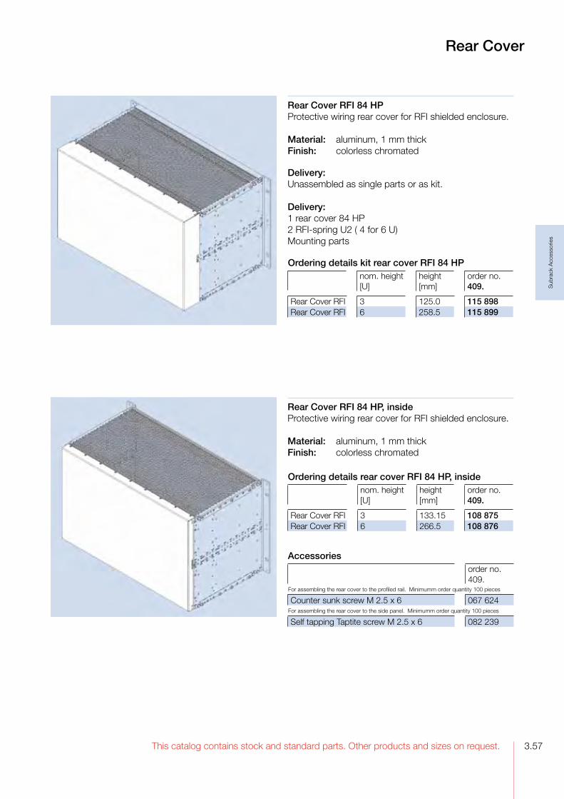
3.57This catalog contains stock and standard parts. Other products and sizes on request.
Sub
rack
Acc
esso
ries
Rear Cover RFI 84 HPProtective wiring rear cover for RFI shielded enclosure.
Material: aluminum, 1 mm thickFinish: colorless chromated
Delivery:Unassembled as single parts or as kit.
Delivery: 1 rear cover 84 HP2 RFIspring U2 ( 4 for 6 U)Mounting parts
Rear Cover
Rear Cover RFI 84 HP, insideProtective wiring rear cover for RFI shielded enclosure.
Material: aluminum, 1 mm thickFinish: colorless chromated
Ordering details kit rear cover RFI 84 HPnom. height [U]
height[mm]
order no. 409.
Rear Cover RFI 3 125.0 115 898Rear Cover RFI 6 258.5 115 899
Ordering details rear cover RFI 84 HP, insidenom. height [U]
height[mm]
order no. 409.
Rear Cover RFI 3 133.15 108 875Rear Cover RFI 6 266.5 108 876
Accessoriesorder no.409.
For assembling the rear cover to the profiled rail. Minimumm order quantity 100 pieces
Counter sunk screw M 2.5 x 6 067 624For assembling the rear cover to the side panel. Minimumm order quantity 100 pieces
Self tapping Taptite screw M 2.5 x 6 082 239

This catalog contains stock and standard parts. Other products and sizes on request.3.58
Sub
rack
Acc
esso
ries
Blind Front Panel for Subrack DividerFor covering of the divider strip. Optional with RFIsprings for a RFI shielded front.
Material: aluminumFinish: colorless chromatedDimensions: 2 HP x 6 U
order no.: 409. 116 319
Subrack Divider
for subrack FLEXIBLE and RFISHIELDED
Subrack Divider Kit 2 x 3 U 42 HP and 6 U 40 HPThe divider separates a 6 U subrack into a field for 6 U PCB’s and 2 fields of 3 U.
Finish: colorless chromated
Delivery:1 double front profile 2xVE143 HP chromated1 double rear profile 2xHK43 HP anodized2 divider stripsMounting partsAssembly:
The short horizontal rails are assembled to the side panel. The dividing strip is inserted into the horizontal rail groove, fixed with a rotating motion and mounted on the short horizontal rails.
Positioning note:For optimum use of available space in the subrack, PCB’s of 6 U should be mounted left, and the 3 U on the right. In this case the dividing strip requires only 1 HP, otherwise 2 HP for the necessary air and leakage paths.
Single Parts
AccessoriesCounter sunk screw M 4 x 16 For assembly of the divider strip to the horizontal rail:
Minimum order quantity 100 pieces
order no.: 409. 107 342
��
����
����
���
����
�
����
��
��
����
���
���
����
�
����
�
����
���
����
���
����
���
������
��
���
���
����
���
������
��
���
Divider Strip
Material: aluminumfinish: chromatedDimensions: 6 U
order no.: 409. 078 942
order no.: 409. 082 063
Accessoriesorder no. 409.
RFIspring F3 3 U 111 112RFIspring F3 6 U 111 116
Needed 1 x 6 U and 2 x 3 U RFIsprings
For assembly of the front panel to the horizontal railMinimum order quantity 100 pieces
Oval head screw M 2.5 x 11.3
101 917

3.59This catalog contains stock and standard parts. Other products and sizes on request.
Sub
rack
Acc
esso
ries
Subrack Divider,Horizontal Mounting Frame
for subrack FLEXIBLE and RFISHIELDED
Subrack Divider Kit 2 x 3 U - 84 HPFor partitioning a 6 U subrack in 2 x 3 U.
Delivery:1 double front profile 2xVE1 85HP colorless chromated1 double rear profile 2xHK 85HP anodizedMounting parts
Horizontal Mounting Frame20 HP for horizontal mounting of 6 U PCB‘s in 3 U subracks.The horizontal mounting frame needs52 HP in the width. For 84 HP subracks are availablePlaced right:52 HP for horizontal mounting frame,32 HP for 3 UPCB‘sPlaced left:52 HP for horizontal mounting frame,1 HP for air and leakage paths, 31 HP for 3 UPCB‘s.
AccessoriesThreaded strip 20 x M 2.5
order no.: 409. 072 533
order no.: 409. 166 270
Ordering details for horizontal mounting frame kits
finishnom. depth [mm]
type alpha order no. 409.
type beta order no. 409.
type delta order no. 409
6 U anodized userdefined 069 047 064 947 064 6876 U RFI chromated 160 161 161 161 1656 U RFI chromated 220 161 162 161 166

This catalog contains stock and standard parts. Other products and sizes on request.3.60
Sub
rack
Acc
esso
ries
for subrack FLEXIBLE Fs, RFISHIELDED and InterRail
Wall and Door Installation Profile KitFor mounting subracks in a door, switch panel etc.The installation profiles are mounted to the side panel by means of the mounting screws to the horizontal rails.
Material: aluminumFinish: anodized
Delivery: 2 wall installation profiles
Separating WallFor separating a subrack int two fields.
Material: aluminumFinish: blank
Delivery: 1 separating wall Mounting parts
Ordering details kitnom. depth 160 mm order no. 409.
nom. depth 220 mm order no. 409.
Separating wall 3 U 122 648 122 649Separating wall 6 U 122 650 122 651
Partition Wall, Separating WallWall and Door Installation Profiles
Partition WallFor partitioning of a subrack part. The partition wall 6 U can also be used as a RFI shielded subrack divider in 6 U and 2x3 U parts.
Delivery:1 partition wall1 front panel 2 HPMounting parts
Ordering details kitnom. depth 160 mm order no. 409.
nom. depth 220 mm order no. 409.
Partition wall 3 U 116 333 116 334Partition wall 6 U 116 335 116 336
Ordering details kitorder no. 409.
Wall installation profile 42 HP 108 045Wall installation profile 84 HP 108 012
Accessories3 U order no. 409.
6 U order no. 409.
Shielding kit 116 416 116 418
consists of: pieces pieces
RFIspring F3 3 U 2 2RFIspring F3 6 U 1RFIspring M P1 1 2Clamping plate 1 2Mounting parts 1 1

3.61This catalog contains stock and standard parts. Other products and sizes on request.
Sub
rack
Acc
esso
ries
Labelling Rail, Locking Rail Label Strip
for subrack FLEXIBLE Fs, RFISHIELDED, InterRail
Labelling Rail 84 HPThis hinged labelling rail is mounted on the subrack flanges. Normally it is placed in front of the front panels. For ejecting a PCB, the rail is turned down.
order no.: 409. 121 941
Label StripSelf adhesive. For identifiying PCB slots in the subrack. The PCB slot number can be read thru the hole in the front panel.Note: The label strip cannot be read while using the RFI spring P2.
Material: PC/PEfoilColor: yellow/black
DeliveryMinimum purchase: 18 pieces on a papersheet.
Ordering details kitorder no. 409.
Label strip 01 84 024 738Label strip 84 01 024 740
Locking Rail 84 HPFor locking of PCB‘s witout front panels.The locking rail is mounted at the horizontal rail in front of the PCB‘s. A labeling strip can be insert into a groove.
order no.: 409. 120 790
Delivery:1 labelling rail2 mounting flanges2 hinge bracketMounting parts
Delivery:1 locking rail1 rubberMounting parts

This catalog contains stock and standard parts. Other products and sizes on request.3.62
Sub
rack
Acc
esso
ries
Threaded Strips
Threaded Strip M 2.5For attaching the front panels and assembly parts at the wiring field.
Material: steelFinish: galvanized, chromated
Threaded Strip M 2.5 addableThis threaded strip could be added to other strips and the space between the holes always adds up 5.08 mm.
Material: steelFinish: galvanized, chromated
070168
034636
Threaded Strip M 2.5 - stainless steelFor attaching the front panels and assembly parts at the wiring field.This threaded strip is for nonmagnetic applications.
Material: stainless steelFinish: blank
118606
5
a
5,084,93(n�1) x 5.08 = b 1,5
M 2,5
5
a
5,084,93(n�1) x 5.08 = b 1,5
M 2,5
Ordering details threaded strip M 2.5n = number of threads
a[mm]
b[mm]
order no. 409.
20 106.38 96.52 131 68821 111.46 101.60 130 88328 147.02 137.16 131 70132 167.34 157.48 131 54836 187.66 177.80 103 77742 218.14 207.28 100 84384 431.50 421.64 091 255
Ordering details threaded strip M 2.5 addablen = number of threads
a[mm]
b[mm]
order no. 409.
10 50.80 45.72 131 83620 101.60 96.52 131 84528 142.24 137.16 106 75142 213.36 207.28 131 81384 426.72 421.64 131 478
Ordering details threaded strip M 2.5 - stainless steeln = number of threads
a[mm]
b[mm]
order no. 409.
84 431.50 421.64 118 608
5
a
5,082,54(n�1) x 5.08 = b 1,5
M 2,5
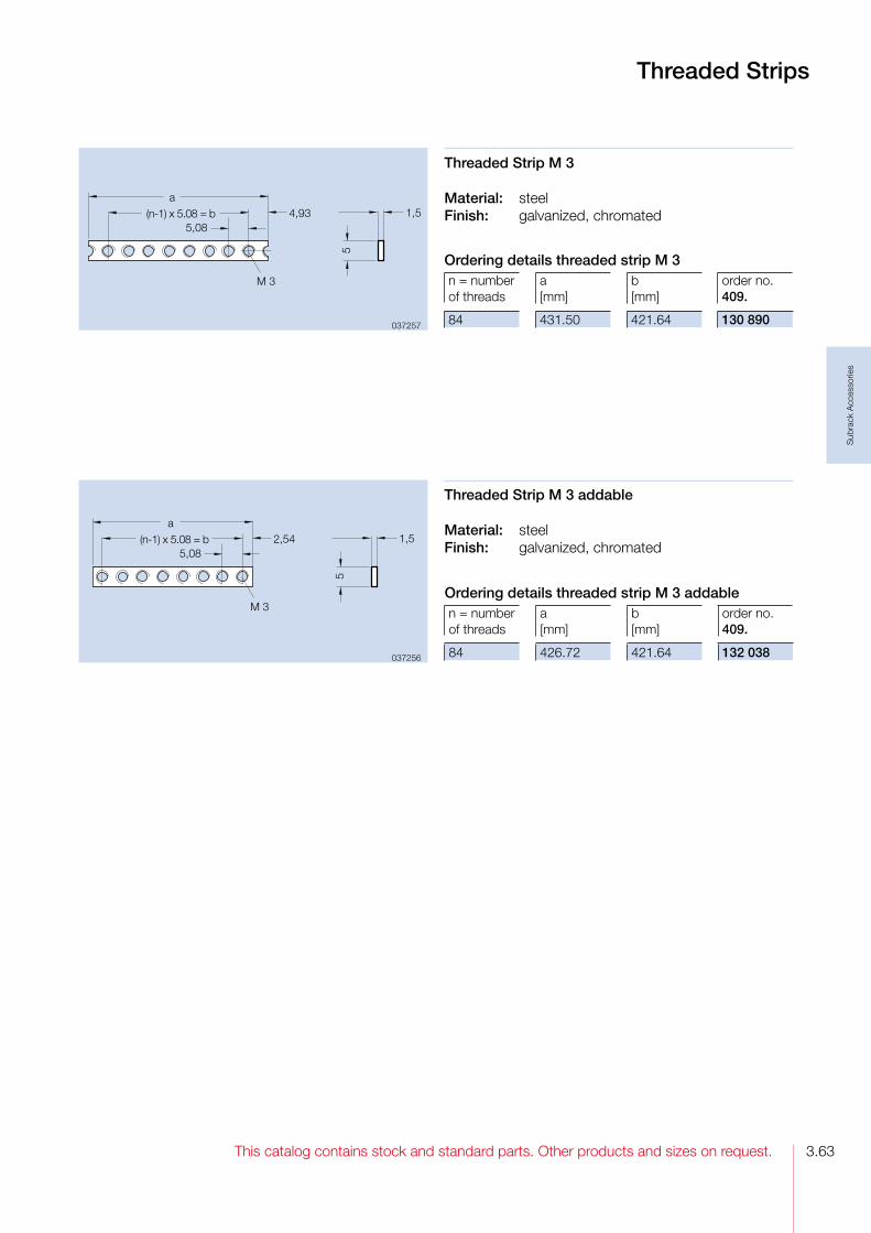
3.63This catalog contains stock and standard parts. Other products and sizes on request.
Sub
rack
Acc
esso
ries
Threaded Strip M 3
Material: steelFinish: galvanized, chromated
Threaded Strip M 3 addable
Material: steelFinish: galvanized, chromated
037257
037256
Threaded Strips
5
a
5,082,54(n�1) x 5.08 = b 1,5
M 3
5
a
5,084,93(n�1) x 5.08 = b 1,5
M 3
Ordering details threaded strip M 3n = number of threads
a[mm]
b[mm]
order no. 409.
84 431.50 421.64 130 890
Ordering details threaded strip M 3 addablen = number of threads
a[mm]
b[mm]
order no. 409.
84 426.72 421.64 132 038

This catalog contains stock and standard parts. Other products and sizes on request.3.64
Sub
rack
Acc
esso
ries
Z-Rail A,Mounting Rail B
����
�
��������������������� �
�����
����
����
�
����������������������� �
�����
����
����
112052
023521
Accessories
Mounting parts for assembling the Z-rail A:for 84 HP Zrail, 5 places suggested.Minimum order quantity 100 pieces
order no. 409.
Oval head screw M 2.5 x 8 ISO 7045 094 602Washer 2.7 013 911Fitting bolt M 2.5 x 6.5 (for connectors) 032 708
Mounting Rail B tapped M 2.5For mounting connectors in accordance to IEC 60 603/DIN 41 612.
For mounting at the rear profile on subracks type alpha with insulating strip and insulating bushings.
For mounting at the rear profile on subracks type delta.
Material: aluminumFinish: blank
Ordering details mounting rail B tapped M 2.5n[HP]
a[mm]
b[mm]
order no. 409.
42 212.28 208.28 112 05484 426.44 421.64 112 055
Z-Rail A tapped M 2.5For mounting connectors in accordance to IEC 60 603/DIN 41 612 in subracks type alpha.Mounted on the rear profile.
Material: aluminumFinish: colorless chromated
Ordering details Z-rail A tapped M 2.5n[HP]
a[mm]
b[mm]
Order no. 409.
22 110.68 106.68 024 36142 212.28 208.28 024 38084 426.44 421.64 026 586
Accessories
Mounting parts for assembling the mounting rail B:for 84 HP Zrail, 5 places suggested.Minimum order quantity 100 pieces
order no. 409.
Washer 2.7 013 911Fitting bolt M 2.5 x 6.5 (for connectors) 032 708for type alphaOval head screw M 2.5 x 12 ISO 7045 094 604for type deltaOval head screw M 2.5 x 8 ISO 7045 094 602
22,2

3.65This catalog contains stock and standard parts. Other products and sizes on request.
Sub
rack
Acc
esso
ries
Insulating StripFor insulated mounting of wiring supports, e. g. of the mounting rail B. Mounted between horizontal rail and wiring support.
Technical dataMaterial PPO, fiber glass reinforced
Continous temperature – 40 °C up to + 105 °C
Fire protection class UL 94 V–1
Color gray
Ordering detailslength [HP]
order no. 409.
Insulating strip40 40 061 541Insulating strip84 84 051 981
Insulating Bushing 2.6For use together with mounting rail B and insulating strip.
Technical dataMaterial PC
Continous temperature – 40 °C up to + 115 °C
Fire protection class UL 94 V–0
Color transparent
order no.: 409. 018 055
Insulating Parts

This catalog contains stock and standard parts. Other products and sizes on request.3.66
Sub
rack
Acc
esso
ries
Accessories
Self tapping oval head screw M 2.5 x 5For assembling the card guides to the horizontal railsMinimum order quantity 100 pieces
order no.: 409. 039 691
Card Guide ECONOMY
Ordering details
nom. length [mm]
PCB thickness [mm]
order no. 409.
Card guide ECONOMY 160 1.6 108 173Card guide ECONOMY 220 1.6 047 601
for subrack FLEXIBLE
Card Guide ECONOMY An inexpensive snapin card guide that can also be secured to the horizontal rails with self tapping screws.
Technical dataMaterial Lexan 500
Color gray
Continous temperature – 40 °C up to + 115 °C
Fire protection class UL 94 V–0

3.67This catalog contains stock and standard parts. Other products and sizes on request.
Sub
rack
Acc
esso
ries
Accessories
Grounding contact for front panels
order no.: 409. 058 102
Card Guide UNIVERSAL
Ordering details
nom. length [mm]
PCB thickness [mm]
order no. 409.
Card guide UNIVERSAL 160 1.6 2.0 061 468Card guide UNIVERSAL 220 1.6 2.0 061 469Card guide UNIVERSAL 280 1.6 2.0 061 526
Card Guide UNIVERSALThis is an allpurpose card guide with provision for a spring to contact front panels.
Technical dataMaterial Lexan 500
Color gray
Continous temperature – 40 °C up to + 115 °C
Fire protection class UL 94 V–0
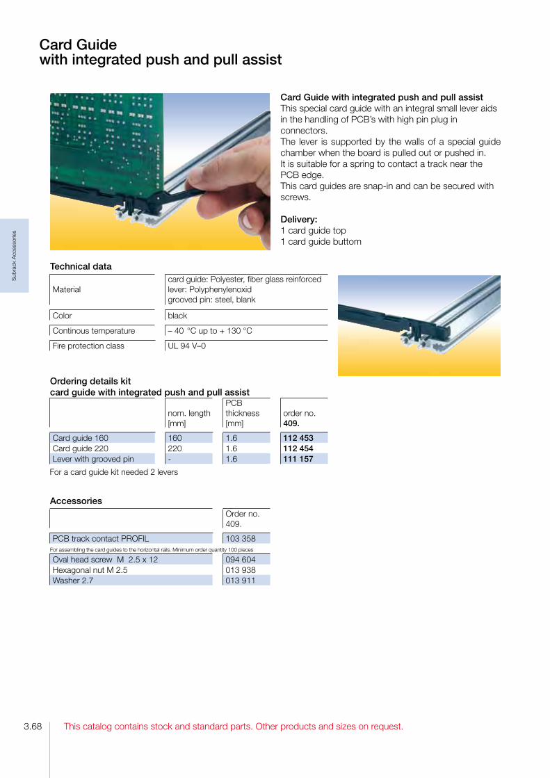
This catalog contains stock and standard parts. Other products and sizes on request.3.68
Sub
rack
Acc
esso
ries
Card Guide with integrated push and pull assistThis special card guide with an integral small lever aids in the handling of PCB’s with high pin plug in connectors.The lever is supported by the walls of a special guide chamber when the board is pulled out or pushed in. It is suitable for a spring to contact a track near the PCB edge.This card guides are snapin and can be secured with screws.
Delivery:1 card guide top1 card guide buttom
Card Guide with integrated push and pull assist
Technical data
Materialcard guide: Polyester, fiber glass reinforcedlever: Polyphenylenoxidgrooved pin: steel, blank
Color black
Continous temperature – 40 °C up to + 130 °C
Fire protection class UL 94 V–0
Ordering details kit card guide with integrated push and pull assist
nom. length[mm]
PCB thickness[mm]
order no.409.
Card guide 160 160 1.6 112 453Card guide 220 220 1.6 112 454Lever with grooved pin 1.6 111 157
For a card guide kit needed 2 levers
AccessoriesOrder no.409.
PCB track contact PROFIL 103 358For assembling the card guides to the horizontal rails. Minimum order quantity 100 pieces
Oval head screw M 2.5 x 12 094 604Hexagonal nut M 2.5 013 938Washer 2.7 013 911

3.69This catalog contains stock and standard parts. Other products and sizes on request.
Sub
rack
Acc
esso
ries
Card Guide CONNFor easy screwless snapon mounting of connectors accordance to IEC 60 603/DIN 41 612. With a provision for a spring to contact front panels and for contacting a track near the PCB edge.This snapin card guides can als be secured with screws.
Delivery:1 card guide CONN top1 card guide CONN bottom
Card Guide CONN
Technical data
Materialnom. length 160: Lexan 500 nom. length 220: PBT
Color gray
Continous temperatureLexan: – 40 °C up to + 115 °C PBT: – 40 °C up to + 130 °C
Fire protection class UL 94 V–0
Ordering details kit card guide CONN
nom. length [mm]
PCB thickness [mm]
order no. 409.
Card guide CONN 160 1.6 083 091Card guide CONN 220 1.6 2.4 116 200
Accessoriesorder no.409.
Grounding contact for front panels 058 102PCB track contact PROFIL 103 358
For assembling the card guides to the horizontal rails. Minimum order quantity 100 pieces
Oval head screw M 2.5 x 12 094 604Hexagonal nut M 2.5 013 938Washer 2.7 013 911

This catalog contains stock and standard parts. Other products and sizes on request.3.70
Sub
rack
Acc
esso
ries
Card Guide VIBLattice construction for heavy mechanical loads. With a provision for a spring to contact front panels and for contacting a track near the PCB edge.This card guides can be snapped in and/or secured with screws.
Two versions:1. With pressedin nut M 2.5for assembly to the horizontal rail with oval head screws M 2.5 x 12
2. Without a nut, but one can be added in the existing hexagonal molding.
Card Guide VIB
Ordering details card guide VIB
nom. length [mm]
PCB thickness [mm] snapin
secured withscrews
order no. 409.
bottom 80 1.6 2.4 yes 115 171top 80 1.6 2.4 yes 115 236with nut M 2.5 100 1.6 yes yes 108 157without nut 100 1.6 yes yes 108 101with nut M 2.5 160 1.6 yes 059 632without nut 160 1.6 yes yes 109 058without nut 160 2.0 yes yes 069 774without nut 160 2.4 yes yes 080 068without nut 180 1.6 yes yes 085 010with nut M 2.5 220 1.6 yes 059 634without nut 220 1.6 yes yes 108 120without nut 220 2.4 yes yes 101 276with nut M 2.5 280 1.6 yes 059 636
Technical dataMaterial Lexan 500
Colornom. length 80 mm: black nom. length 100 mm: blackothers: gray
Continous temperature – 40 °C up to + 115 °C
Fire protection class UL 94 V–0
Accessoriesorder no.409.
Grounding contact for front panels 058 102PCB track contact PROFIL 103 358
For assembling the card guides to the horizontal rails. Minimum order quantity 100 pieces
Oval head screw M 2.5 x 12 094 604Hexagonal nut M 2.5 013 938Washer 2.7 013 911

3.71This catalog contains stock and standard parts. Other products and sizes on request.
Sub
rack
Acc
esso
ries
Card Guide VARIOThis is a length variable card guide constructed from 3 pieces. The center piece can be cut to any length.With a provision for a spring to contact front panels. These snapin end pieces can also be secured with screws.
Two versions:1. With pressedin nut M 2.5for assembly to the horizontal rail with oval head screws M 2.5 x 12
2. Without a nut, but one can be added in the existing hexagonal molding.
Card Guide VARIO
Ordering details card guide VARIO
length [mm]
PCB thickness [mm]
order no. 409.
Pair of end pieceswith nut M 2.5 1.6 061 086without nut 1.6 061 051with nut M 2.5 2.4 061 088without nut 2.4 061 052center pieceplastic 1000 1.6 061 061aluminum 1000 1.6 061 059plastic 1000 2.4 061 062aluminum 1000 2.4 061 060
Technical data
Materialend pieces: Noryl SE1 center piece: aluminum or Noryl ENV 125
Colorend pieces: black center piece: black, silver
Continous temperature – 40 °C up to + 105 °C
Fire protection class UL 94 V–1
Accessoriesorder no.409.
Grounding contact for front panels 058 102For assembling the card guides to the horizontal rails. Minimum order quantity 100 pieces
Oval head screw M 2.5 x 12 094 604Hexagonal nut M 2.5 013 938Washer 2.7 013 911

This catalog contains stock and standard parts. Other products and sizes on request.3.72
Sub
rack
Acc
esso
ries
Card Guide IEEEThis card guide is in accordance to specification IEEE 1101.10.The required coding of the IEEE is integrated in the card guide head.With provision for the IEEE contact spring for grounding of the alignmentpins of the PCB‘s front panel.Also with a provision for contacting a track near the PCB edge.This snapin card guides can be secured with screws.
Card Guide IEEE andCard Guide IEEE with 1/2 HP lateral offset
Card Guide IEEE with 1/2 HP lateral offsetThis card guide is also in accordance to specification IEEE 1101.10. For CompactPCIpower supplies and for Plugin units fitted with SMD.With provision for the IEEE contact spring for grounding of the alignmentpins of the PCB‘s front panel.Also with a provision for contacting a track near the PCB edge.This card guide is secured with screws.
Technical dataMaterial PBT
Color black or red
Continous temperature – 40 °C up to + 115 °C
Fire protection class UL 94 V–0
Technical dataMaterial PBT / VALOX 467
Color green
Continous temperature – 40 °C up to + 115 °C
Fire protection class UL 94 V–0
Ordering details for card guide IEEE with 1/2 HP lateral offset
colornom. length [mm]
PCB thickness [mm]
order no. 409.
green 160 1.6 2.4 130 889
Accessories for Card Guide IEEEorder no.409.
contact spring IEEE 113 450coding pin IEEE gray 113 713coding pin IEEE red 116 442PCB track contact PROFIL 103 358
For assembling the card guides to the horizontal rails. Minimum order quantity 100 pieces
Lens head screw M 2.5 x 12 094 604Hexagonal nut M 2.5 013 938Washer 2.7 013 911
Ordering details for card guide IEEE
colornom. length [mm]
PCB thickness [mm]
order no. 409.
black 160 1.6 2.4 113 400black 220 1.6 2.4 131 973red 160 1.6 2.4 116 440
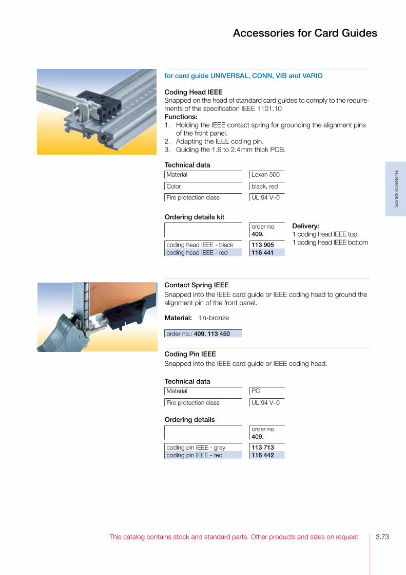
3.73This catalog contains stock and standard parts. Other products and sizes on request.
Sub
rack
Acc
esso
ries
Accessories for Card Guides
for card guide UNIVERSAL, CONN, VIB and VARIO
Coding Head IEEESnapped on the head of standard card guides to comply to the requirements of the specification IEEE 1101.10Functions:1. Holding the IEEE contact spring for grounding the alignment pins of the front panel.2. Adapting the IEEE coding pin.3. Guiding the 1.6 to 2.4 mm thick PCB.
Technical dataMaterial Lexan 500
Color black, red
Fire protection class UL 94 V–0
Coding Pin IEEESnapped into the IEEE card guide or IEEE coding head.
Technical dataMaterial PC
Fire protection class UL 94 V–0
Delivery:1 coding head IEEE top1 coding head IEEE bottom
Contact Spring IEEESnapped into the IEEE card guide or IEEE coding head to ground the alignment pin of the front panel.
Material: tinbronze
Ordering details kitorder no. 409.
coding head IEEE black 113 905coding head IEEE red 116 441
Ordering detailsorder no. 409.
coding pin IEEE gray 113 713coding pin IEEE red 116 442
order no.: 409. 113 450

This catalog contains stock and standard parts. Other products and sizes on request.3.74
Sub
rack
Acc
esso
ries
Grounding Contact for Front PanelsFor premating grounding. In connection with front connector with male contact.
Material: tinbronzefinish: tinplated order no.: 409. 058 102
AccessoriesFront connector with male contact
order no. 409.
top 107 728bottom 107 727
Cover for Ventilation OpeningsSnapping into the horizontal rails. Covers the ventilation openings between card guides.
Material: plasticFire protection class: UL 94 V0
Accessories for Card Guides
PCB Lead-InFor easy leadin of the PCB into the card guide.
Technical data
MaterialPolycarbonat, 10% fiber glass reinforced
Color gray, similar RAL 7044
Fire protection class UL 94 V–0
Delivery:1 PCB leadin top1 PCB leadin bottom
order no.: 409. 092 785
Ordering detailsnom. length [mm]
order no. 409.
Front connector with male contact 4 HP 160 106 530Front connector with male contact 4 HP 220 106 531
PCB Track Contact PROFILSnapped into a card guide, connecting a PCB’s edge to the horizontal rail of a subrack.
Technical dataMaterial tinbronze
Finish tinplated
Fire protection class UL 94 V–0
order no.: 409. 103 358

3.75This catalog contains stock and standard parts. Other products and sizes on request.
Sub
rack
Acc
esso
ries
PCB Locking
PCB Locking Spring, plasticSecures PCB without front panels.
Technical dataMaterial Lexan 500
Color black
Fire protection class UL 94 V–0
order no.: 409. 052 720
PCB Locking Device KitSecures PCB’s without front panels. Used for easy locking and ejecting of PCB’s
Technical data
Materialhandle: PBT pin: steel
Color black
Fire protection class UL 94 V–0
DeliveryKit, unassembled
Delivery:2 handles2 pins2 PCB locking springs
Ordering details kitorder no. 409.
PCB locking device 1.6 068 698PCB locking device 2.4 102 297

This catalog contains stock and standard parts. Other products and sizes on request.3.76
Sub
rack
Acc
esso
ries
Front Panels
In addition to the wide range of standard front panels we also provide on request individual customer specific custom front panels with punching, surface finish and silk screening.Textured or smooth painted in all revelant RALcolors, abrasionresistant silkscreen printing as well as color coordinated engraving gives your front panel an individual appearance.
Please ask your local representative for your individual front panel design.
You find your contact person on our home-page
www.intermas-el.com

3.77This catalog contains stock and standard parts. Other products and sizes on request.
Sub
rack
Acc
esso
ries
√ Blind Front Panels
√ Front Panels with Handle√ Handles
√ Front Panels with Ejector Handle√ Ejector Handles
√ Front Panels with IEEE Handle√ IEEE-Handles
√ Plastic Front Panels
Front Panels and Handles
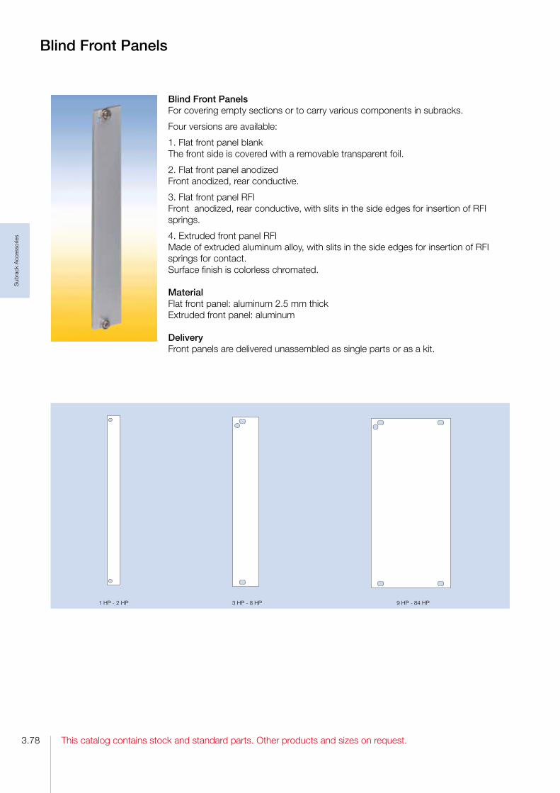
This catalog contains stock and standard parts. Other products and sizes on request.3.78
Sub
rack
Acc
esso
ries
Blind Front PanelsFor covering empty sections or to carry various components in subracks.
Four versions are available:
1. Flat front panel blank The front side is covered with a removable transparent foil.
2. Flat front panel anodizedFront anodized, rear conductive.
3. Flat front panel RFIFront anodized, rear conductive, with slits in the side edges for insertion of RFI springs.
4. Extruded front panel RFIMade of extruded aluminum alloy, with slits in the side edges for insertion of RFI springs for contact.Surface finish is colorless chromated.
Material Flat front panel: aluminum 2.5 mm thickExtruded front panel: aluminum
DeliveryFront panels are delivered unassembled as single parts or as a kit.
Blind Front Panels
1 HP 2 HP 3 HP 8 HP 9 HP 84 HP

3.79This catalog contains stock and standard parts. Other products and sizes on request.
Sub
rack
Acc
esso
ries
Ordering details blind front panels (flat front panel)
nom. width [HP]
3 U
blankorder no.409.
3 Uanodized/conductive order no. 409.
6 U
blankorder no.409.
6 Uanodized/conductive order no. 409.
Blind front panel 1 097 201 097 601 Blind front panel 2 097 202 097 602 Blind front panel 3 097 203 097 603 Blind front panel 4 097 204 097 404 097 604 097 804Blind front panel 5 097 205 097 605 Blind front panel 6 097 206 097 406 097 606 097 806Blind front panel 7 097 207 097 607 Blind front panel 8 097 208 097 408 097 608 097 808Blind front panel 10 097 210 097 610 Blind front panel 12 097 212 097 412 097 612 097 812Blind front panel 14 097 214 097 414 097 614 097 814Blind front panel 21 097 221 097 421 097 621 097 821Blind front panel 28 097 228 097 428 097 628 097 828Blind front panel 42 097 242 097 442 097 642 097 842Blind front panel 84 097 284 097 484 097 684 097 884
AccessoriesMinimum order quantity 100 pieces
pieces for 12 HP
pieces for 38 HP
pieces for985 HP
order no. 409.
Screw retainer M 2.5 gray 2 4 100 539Screw retainer M 2.5 black 2 4 100 538Crosshead screw M 2.5 x 11.3 2 2 4 101 917
Blind Front Panels
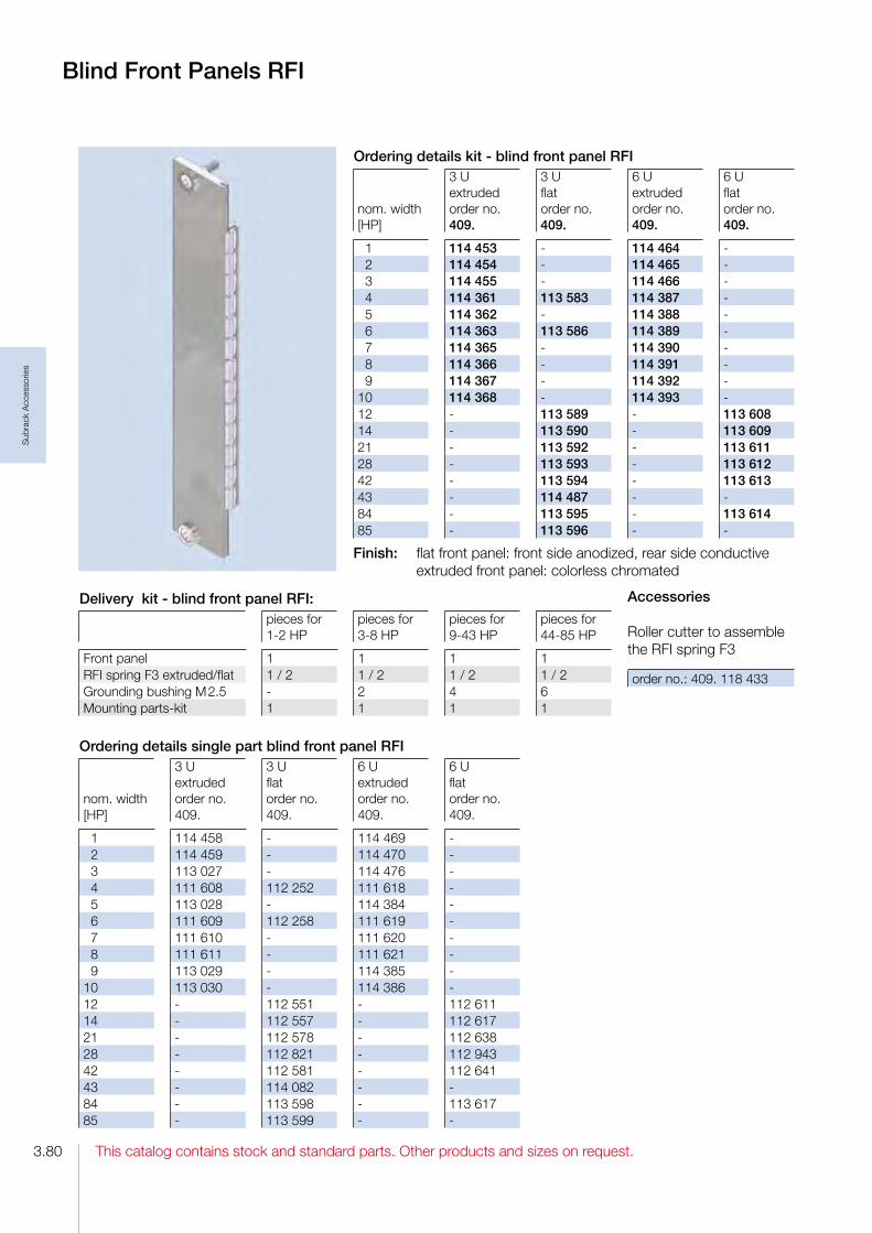
This catalog contains stock and standard parts. Other products and sizes on request.3.80
Sub
rack
Acc
esso
ries
Blind Front Panels RFI
Finish: flat front panel: front side anodized, rear side conductive extruded front panel: colorless chromated
Ordering details kit - blind front panel RFI
nom. width [HP]
3 U extrudedorder no. 409.
3 U flatorder no. 409.
6 U extrudedorder no. 409.
6 U flatorder no. 409.
1 114 453 114 464 2 114 454 114 465 3 114 455 114 466 4 114 361 113 583 114 387 5 114 362 114 388 6 114 363 113 586 114 389 7 114 365 114 390 8 114 366 114 391 9 114 367 114 392 10 114 368 114 393 12 113 589 113 60814 113 590 113 60921 113 592 113 61128 113 593 113 61242 113 594 113 61343 114 487 84 113 595 113 61485 113 596
Delivery kit - blind front panel RFI:pieces for 12 HP
pieces for 38 HP
pieces for 943 HP
pieces for4485 HP
Front panel 1 1 1 1RFI spring F3 extruded/flat 1 / 2 1 / 2 1 / 2 1 / 2Grounding bushing M 2.5 2 4 6Mounting partskit 1 1 1 1
Ordering details single part blind front panel RFI
nom. width [HP]
3 U extruded order no. 409.
3 U flat order no. 409.
6 U extruded order no. 409.
6 U flat order no. 409.
1 114 458 114 469 2 114 459 114 470 3 113 027 114 476 4 111 608 112 252 111 618 5 113 028 114 384 6 111 609 112 258 111 619 7 111 610 111 620 8 111 611 111 621 9 113 029 114 385 10 113 030 114 386 12 112 551 112 61114 112 557 112 61721 112 578 112 63828 112 821 112 94342 112 581 112 64143 114 082 84 113 598 113 61785 113 599
Accessories
Roller cutter to assemble the RFI spring F3
order no.: 409. 118 433

3.81This catalog contains stock and standard parts. Other products and sizes on request.
Sub
rack
Acc
esso
ries
Front Panels plug-in, hinged
Hinged Front Panel 85 HPWith slits in the side edges for insertion of RFI springs. The hinge is screwed to the profiled rail of the subrack. An 84 HP threaded strip is needed.To be used in combination with below mentioned flanges only.
Finish: front side anodized, rear side conductive
Delivery:1 front panel1 hinge3 grounding bushingsMounting parts
Delivery: as unassembled kit.Assembled kits on request.
Accessoriesorder no.409.
Profiled rail VE12SFPRFI85 114 562Flange RFI FP 3 U 114 708Flange RFI FP 6 U 114 715RFI spring F3 3 U 111 112RFI spring F3 6 U 111 116
For one flat front panel 2 RFI springs are needed.
Accessoriesorder no.409.
Threaded strip 84 HP 078 428Flange RFI FP 3 U 114 708Flange RFI FP 6 U 114 715RFI spring F3 3 U 111 112RFI spring F3 6 U 111 116
For one flat front panel 2 RFI springs are needed.
Ordering details for kitorder no.409.
Hinged front panel 3 U 113 705Hinged front panel 6 U 113 706
Plug-in Front Panel 85 HPThe front panel bottom edge is inserted in the groove of a specially profiled rail. With slits in the side edges for insertion of RFI springs.To be used in combination with below mentioned flanges only.
Finish: front side anodized, rear side conductive
Delivery:1 front panel3 grounding bushing M 2.53 crosshead screw M 2.5 x 11.3
Ordering details for kitorder no. 409.
Plugin front panel 3 U 113 948Plugin front panel 6 U 113 950

This catalog contains stock and standard parts. Other products and sizes on request.3.82
Sub
rack
Acc
esso
ries
Front Panels with Handle
Front Panels with HandleFor assembly on a PCB.Handle and front connector are screwed on the front panel. The plain front panel is easy to modify.
Four versions are available:
1. Flat front panel blank The front side is covered with a removable transparent foil.
2. Flat front panel anodizedFront anodized, rear conductive.
3. Flat front panel RFIFront anodized, rear conductive. With slits in the side edges for insertion of RFI springs.
4. Extruded front panel RFIMade of extruded aluminum alloy, with slits in the side edges for insertion of RFI springs for contact.Surface finish is colorless chromated.
Material Flat front panel: aluminum 2.5 mm thickExtruded front panel: aluminum
DeliveryFront panels are delivered unassembled as single parts or as a kit.
3 HP 4 HP 6 HP 8 HP 29 HP 84 HP5 HP 9 HP 28 HP
Hole pattern of the front panels

3.83This catalog contains stock and standard parts. Other products and sizes on request.
Sub
rack
Acc
esso
ries
Front Panels with Handle
Ordering details kit -front panel with handle (flat front panels)
nom. width [HP]
3 U anodized/conductive order no. 409.
6 U anodized/conductive order no. 409.
4 107 518 122 624 6 122 622 122 625 8 107 520 122 62610 107 521 122 62712 107 522 122 628
Delivery kit - front panel with handle3 Upieces for38 HP
3 Upieces for912 HP
6 Upieces for38 HP
6 Upieces for912 HP
Front panel 1 1 1 1Handle gray 1 1 2 2Identplate aluminum 1 1 2 2Front connector FEE 1 1 2 2Screw retainer M 2.5 2 4 2 4Mounting parts 1 1 1 1
Ordering details - single part front panel for handle (flat front panel)
nom. width[HP]
3 U blankorder no. 409.
3 U anodized/conductive order no. 409.
6 U blank order no. 409.
6 U anodized/conductive order no. 409.
3 096 403 096 703 4 096 404 096 604 096 704 096 904 5 096 405 096 605 096 705 096 905 6 096 406 096 606 096 706 096 906 7 096 407 096 707 8 096 408 096 608 096 708 096 90810 096 410 096 610 096 710 096 91012 096 412 096 612 096 712 096 91216 096 416 096 716 21 096 421 096 721

This catalog contains stock and standard parts. Other products and sizes on request.3.84
Sub
rack
Acc
esso
ries
Front Panels RFI with Handle
Finish:Flat front panel: front side anodized, rear side conductiveExtruded front panel: colorless chromated
Ordering details kit - front panel RFI with handle
nom. width [HP]
3 U extruded order no. 409.
3 U flat order no. 409.
6 U extruded order no. 409.
6 U flat order no. 409.
3 114 537 114 541 4 114 377 114 404 5 114 378 114 405 6 114 379 114 406 7 114 380 114 407 8 114 381 114 408 10 114 383 114 410 12 113 685 113 693
Delivery kit - front panel RFI with handle3 Upieces for38 HP
3 Upieces for912 HP
6 Upieces for38 HP
6 Upieces for912 HP
Front panel 1 1 1 1Handle gray 1 1 2 2Identplate aluminum 1 1 2 2Front connector metal 2 2 3 3Grounding bushing M 2.5 2 4 2 4Mounting parts 1 1 1 1
Ordering details single part front panel RFI for handle
nom. width[HP]
3 U extruded order no. 409.
3 U flat order no. 409.
6 U extruded order no. 409.
6 U flat order no. 409.
3 114 538 114 540 4 114 370 113 711 114 396 5 114 371 114 397 6 114 372 113 723 114 399 7 114 373 114 400 8 114 374 113 725 114 401 10 114 376 114 403 12 113 729 113 762
Accessoriesorder no. 409.
For one flat front panel 2 RFIsprings are needed.
RFI spring F3 3 U 111 112RFI spring F3 6 U 111 116
For assemble the RFI spring F3
Roller cutter 118 433

3.85This catalog contains stock and standard parts. Other products and sizes on request.
Sub
rack
Acc
esso
ries
Handle and Handle Strip
Handle FPAssembled with M 2.5 screws and with 1 additional self tapping screw from 6 HP. The handle is held against torsion by means of two nipples.
Ident Plate for handle FP.The ident plate is markable and printable, snapped in after mounting the handle to the front panel.
022 722
058 719
Technical data
MaterialPolycarbonate, 10% fiberglass reinforced
Color gray RAL 7032, black
Continous temperature – 40 °C to + 100 °C
Fire protection class UL 94 V–0
Ordering details handle FP
width[HP]
length[mm]
grayorder no. 409.
blackorder no. 409.
3 13.80 102 115 041 657 4 18.88 102 114 100 667 5 23.96 103 005 103 205 6 29.04 103 006 103 206 7 34.12 103 007 103 207 8 39.20 103 008 103 208
Ordering details ident-plate
width[HP]
length[mm]
aluminumorder no. 409.
crystal clearorder no. 409.
3 13.80 017 929 089 238 4 18.88 017 956 089 240 5 23.96 022 791 6 29.04 022 792 7 34.12 022 793 8 39.20 022 794 10 49.36 022 796 12 59.52 022 798 16 79.84 022 802 21 105,24 022 807 42 211.92 040 652
Accessories handles: Minimum order quantity each 100 pieces
order no.409.
Pan head screw M 2.5 x 16 094 605Washer 2.7 013 911Hexagonal nut M 2.5 DIN 439 013 938Self tapping screw M 2.5 x 10 040 401
Ordering details handle strip FP
width[HP]
length[mm]
grayorder no. 409.
blackorder no. 409.
10 49.36 103 810 058 91012 59.52 103 812 058 91216 79.84 103 816 058 91621 105.24 103 821 058 92142 211.92 103 842 058 942
Technical data
Materialaluminum orPolycarbonate, crystal clear
Finish Alu: silver silkanodized
Continous temperature PC: – 40 °C to + 115 °C
Fire protection class PC: UL 94 V–2

This catalog contains stock and standard parts. Other products and sizes on request.3.86
Sub
rack
Acc
esso
ries
Front Panels with Ejector Handle
Front Panels with Ejector HandleFor easy release of PCB’s with high pin connections.The ejector handle is extends through the front panel and is screwed together with the bearing bushing at the front connector.
Four versions are available:
1. Flat front panel blank. The front side is covered with a removable transparent foil.
2. Flat front panel anodized.Front anodized, rear conductive.
3. Flat front panel RFIFront anodized, rear conductive. With slits in the side edges for insertion of RFI springs.
4. Extruded front panel RFIMade of extruded aluminum alloy, with slits in the side edges for insertion of RFI springs for contact.Surface finish is colorless chromated.
Material Flat front panel: aluminum 2.5 mm thickExtruded front panel: aluminum
DeliveryFront panels are delivered unassembled as single parts or as a kit.
4 HP 8 HP 9 HP 21 HP
Hole pattern of the front panels

3.87This catalog contains stock and standard parts. Other products and sizes on request.
Sub
rack
Acc
esso
ries
Front Panels with Ejector Handle
Ordering details kit - front panel with ejector handle(flat front panels)
nom. width[HP]
3 U
blank order no. 409.
3 U anodized/conductive order no. 409.
6 U
blank order no. 409.
6 U anodized/conductive order no. 409.
4 168 913 168 919 122 639 122 645 5 168 914 122 640 6 168 915 122 641 8 168 916 168 920 122 642 122 64610 168 917 122 643 12 168 918 168 921 122 644 122 647
Delivery kit - front panel with ejector handle 3 U pieces for48 HP
3 Upieces for912 HP
6 U pieces for48 HP
6 Upieces for912 HP
Front panel 1 1 1 1Ejector handle top, gray 1 1Ejector handle bottom, gray 1 1 1 1Bearing bushing 1 1 2 2Front connector metal 2 2 2 2Front panel support plugin 2 2Screw retainer M 2.5 2 4 2 4Mounting parts 1 1 1 1
Ordering details single part front panel for ejector handle (flat front panels)
nom. width [HP]
3 U blank
order no. 409.
3 U anodized/conductive
order no.409.
6 U for support plugedin blank
order no. 409.
6 U for support plugedin anodized/conductive order no. 409.
6 U for support screwedblank
order no. 409.
6 U for support screwedanodized/conductive order no.409.
4 168 900 168 908 102 404 102 344 102 454 102 384 5 168 901 102 405 6 168 902 102 406 8 168 903 168 909 102 408 102 348 102 458 102 38810 168 904 102 410 12 168 905 168 910 102 412 102 352 102 462 102 39216 168 906 168 911 102 416 102 356 21 168 907 168 912 102 421 102 361

This catalog contains stock and standard parts. Other products and sizes on request.3.88
Sub
rack
Acc
esso
ries
Front Panels RFI with Ejector Handle
Finish:Flat front panel: front side anodized, rear side conduvtiveExtruded front panel: colorless chromated
Ordering details - kit front panel RFI with ejector handle
nom. width[HP]
3 U extrudedorder no. 409.
3 Uflat order no. 409.
6 U extruded order no. 409.
6 Uflat order no. 409.
4 113 655 113 620 113 662 5 113 656 113 663 6 113 657 113 622 113 665 7 113 658 113 667 8 113 659 113 668 9 113 660 113 669 10 113 661 113 670 12 113 626 113 640
Delivery kit - front panel RFI with ejector handle3 Upieces for 48 HP
3 U pieces for 912 HP
6 U pieces for 48 HP
6 U pieces for 912 HP
Front panel 1 1 1 1ejector handle top, gray 1 1ejector handle bottom, gray 1 1 1 1Bearing bushing 1 1 2 2Front connector metal 2 2 2 2Front panel support plugin 2 2Grounding bushing M 2.5 2 4 2 4Mounting parts 1 1 1 1
Ordering details single part front panel RFI for ejector handle
nom. width[HP]
3 U extrudedorder no. 409.
3 Uflat order no. 409.
6 U extruded order no. 409.
6 Uflat order no. 409.
4 111 847 112 644 111 613 5 113 170 113 147 6 111 604 112 650 111 614 7 111 605 111 615 8 111 606 111 616 9 113 171 113 148 10 113 172 113 149 12 112 668 112 725
Accessoriesorder no. 409.
For one flat front panel 2 RFIsprings are needed.
RFI spring F3 3 U 111 112RFI spring F3 6 U 111 116
For assemble the RFI spring F3
Roller cutter 118 433
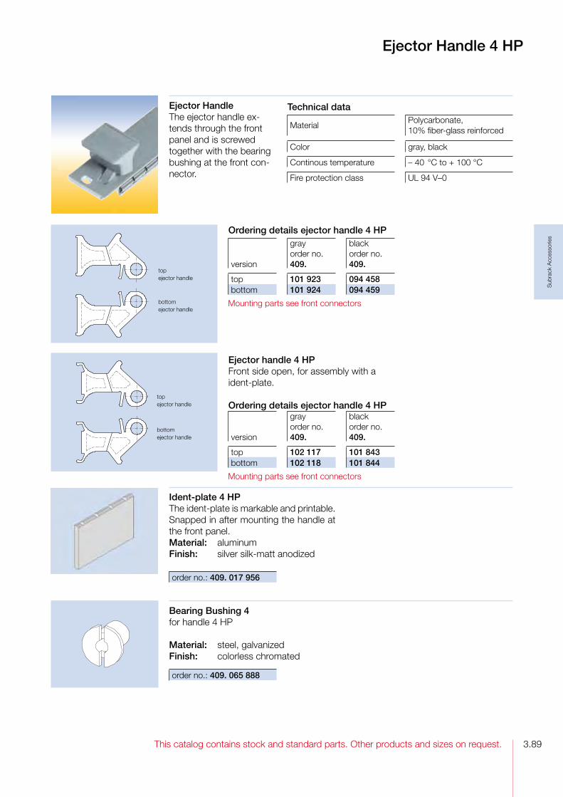
3.89This catalog contains stock and standard parts. Other products and sizes on request.
Sub
rack
Acc
esso
ries
Ejector Handle 4 HP
Ejector HandleThe ejector handle extends through the front panel and is screwed together with the bearing bushing at the front connector.
Ident-plate 4 HPThe identplate is markable and printable. Snapped in after mounting the handle at the front panel.Material: aluminumFinish: silver silkmatt anodized
order no.: 409. 017 956
Bearing Bushing 4for handle 4 HP
Material: steel, galvanizedFinish: colorless chromated
order no.: 409. 065 888
topejector handle
bottomejector handle
topejector handle
bottomejector handle
Technical data
MaterialPolycarbonate,10% fiberglass reinforced
Color gray, black
Continous temperature – 40 °C to + 100 °C
Fire protection class UL 94 V–0
Ordering details ejector handle 4 HP
version
gray order no. 409.
blackorder no. 409.
top 101 923 094 458bottom 101 924 094 459
Mounting parts see front connectors
Ejector handle 4 HPFront side open, for assembly with a identplate.
Ordering details ejector handle 4 HP
version
gray order no. 409.
black order no. 409.
top 102 117 101 843bottom 102 118 101 844
Mounting parts see front connectors

This catalog contains stock and standard parts. Other products and sizes on request.3.90
Sub
rack
Acc
esso
ries
Front Panels RFI with IEEE Handle
Front Panels with IEEE Handle For easy pull of PCB’s with high density connectorsaccordance specification IEEE 1101.10.The assambled handle kit is stuck in the milled space of the front panel and is secured with a clamped spring. Afterwards the PCB are screwed on the intergrated front connector.
Two versions with IEEE handle are available:
1. Flat front panel RFI Front anodized, rear conductive. With slits in the side edges for insertion of RFI springs.
2. Extruded front panel RFIMade of extruded aluminum alloy, with slits in the side edges for insertion of RFI springs or for contacting.Surface finish is colorless chromated.
DeliveryFront panels are delivered with the assambled IEEE handle as single parts or as a kit.
4 HP 9 HP 12TE
Hole pattern of the front panels
5 HP 8 HP
Technical data
MaterialFront panel: aluminumHandle: Polycarbonate
Finish
Front panel: flat: front side anodized,rear side conductive extruded: colorless chromated
Color handle: RAL 7035 or black
Continous temperature – 40 °C to + 100 °C
Fire protection class UL 94 V–0
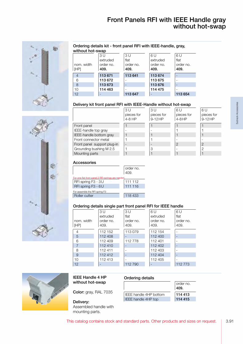
3.91This catalog contains stock and standard parts. Other products and sizes on request.
Sub
rack
Acc
esso
ries
Front Panels RFI with IEEE Handle graywithout hot-swap
IEEE Handle 4 HP without hot-swap
Color: gray, RAL 7035
Delivery:Assembled handle with mounting parts.
Ordering details kit - front panel RFI with IEEE-handle, gray, without hot-swap
nom. width [HP]
3 U extrudedorder no.409.
3 U flatorder no.409.
6 U extrudedorder no.409.
6 Uflatorder no. 409.
4 113 671 113 641 113 674 6 113 672 113 675 8 113 673 113 676 10 114 463 114 475 12 113 647 113 654
Delivery kit front panel RFI with IEEE-Handle without hot-swap3 U pieces for 48 HP
3 U pieces for 912 HP
6 U pieces for 48 HP
6 U pieces for 912 HP
Front panel 1 1 1 1IEEEhandle top gray 1 1IEEEhandle bottom gray 1 1 1 1Front connector metal 1 1 Front panel support plugin 2 2Grounding bushing M 2.5 1 3 2Mounting parts 1 1 1 1
Ordering details single part front panel RFI for IEEE handle
nom. width [HP]
3 U extrudedorder no.409.
3 U flatorder no.409.
6 U extrudedorder no.409.
6 U flatorder no.409.
4 112 152 113 079 112 154 5 112 408 112 400 6 112 409 112 778 112 401 7 112 410 112 402 8 112 411 112 403 9 112 412 112 404 10 112 413 112 405 12 112 790 112 773
Ordering detailsorder no.409.
IEEE handle 4HP bottom 114 413IEEE handle 4HP top 114 415
Accessoriesorder no. 409.
For one flat front panel 2 RFIsprings are needed.
RFI spring F3 3 U 111 112RFI spring F3 6 U 111 116
For assemble the RFI spring F3
Roller cutter 118 433

This catalog contains stock and standard parts. Other products and sizes on request.3.92
Sub
rack
Acc
esso
ries
Front Panels RFI with IEEE Handle black with hot-swap
Ordering details kit -extruded front panel RFI with IEEE handle, black, hot-swap in the bottom handle
nom. width [HP]
3 U order no. 409.
6 U order no. 409.
4 122 607 122 610 6 122 608 122 611 8 122 609 122 612
Delivery kit3 U pieces for 48 HP
6 U pieces for 48 HP
Front panel 1 1IEEE handle top black 1IEEE handle bottom black 1 1Micro switch 1 1Front connector metal 1 Front panel support plugin 2Grounding bushing M 2.5 1 Mounting parts 1 1
Accessoriesorder no. 409.
For one flat front panel 2 RFIsprings are needed.
RFI spring F3 3 U 111 112RFI spring F3 6 U 111 116
For assemble the RFI spring F3
Roller cutter 118 433

3.93This catalog contains stock and standard parts. Other products and sizes on request.
Sub
rack
Acc
esso
ries
Plastic Front PanelsOn the rear side of the 2 mm thick front panel is an integrated front connector for attaching 1.6 mm thickness 3 U PCBs. The handle snappes in into the front panel, therefore the front panel can be modified easily.
DeliveryAs single part
Technical data
MaterialPolycarbonate, 10% fiberglass reinforced
Color RAL 7032, pearl gray or black
Continous temperature – 40 °C to + 115 °C
Fire protection class UL 94 V–0
Snap-in HandleFor use with 2 mm thick front panels of plastic. The handle snappes in into the front panel.Front panels aluminum on request
Plastic Front Panel,Snap-in Handle
Ordering details plastic front panel
nom. width [HP]
3 U pearl gray order no. 409.
3 U black order no. 409.
3 035 004 - 4 - - 8 035 665 040 387
AccessoriesMinimum order quantity 100 pieces
order no. 409.
Screw retainer 2 M 2.5, gray 085 689Crosshead screw M 2.5 x 10.8
056 135
Ordering details snap-in handle
nom. width [HP]
RAL 7032order no. 409.
pearl gray order no. 409.
black order no. 409.
3 043 035 035 528 040 385 4 043 036 035 529 040 386
Technical data
MaterialPolycarbonate, 10% fiberglass reinforced
Color RAL 7032, pearl gray or black
Continous temperature – 40 °C to + 105 °C
Fire protection class UL 94 V–0

This catalog contains stock and standard parts. Other products and sizes on request.3.94
Sub
rack
Acc
esso
ries
top
bottom
top
bottom
top
bottom
Front Connector
Front Connector
Material: zinc diecastFinish: untreated
Ordering detailsorder no. 409.
Front connector top 099 731Front connector bottom 099 730
Front Connector with Male ContactFor premating front panel grounding.
Material: zinc diecastFinish: tinplated
Ordering detailsorder no.409.
Front connector top 107 728Front connector bottom 107 727
AccessoriesMinimum order quantity 100 pieces
order no. 409.
Hexagonal nut M 2.5 013 938Counter sunk screw M 2.5 x 6 067 624
Ordering detailsorder no. 409.
Front connector top 065 883Front connector bottom 065 882
Plastic Front Connector
Technical data
MaterialPolycarbonate, 10% fiberglass reinforced
Color gray
Continous temperature – 40 °C to + 100 °C
Fire protection class UL 94 V–0
Accessories
Counter sunk screw M 2.5 x 6 self tappingMinimum order quantity 100 pieces
order no.: 409. 067 624
Accessoriesorder no.409.
Front panel grounding contact 058 102Minimum order quantity 100 pieces
Self tapping counter sunk screw M 2.5 x 6
067 624

3.95This catalog contains stock and standard parts. Other products and sizes on request.
Sub
rack
Acc
esso
ries
Front Connector FEE,Front Panel Support
Technical data
MaterialPolycarbonate, 10% fiberglass reinforced
Color gray
Continous temperature – 40 °C to + 100 °C
Fire protection class UL 94 V–0
order no.: 409. 092 786
Front Panel SupportFor PCB’s with a height over 3 U used with twopiece front connector. Prevents deflection of the front panel when inserting the PCB.
����
��
����
�
�����
� ����
������ �����
����
������
order no.: 409. 024 830
Front Connector FEEWith inserted nut M 2.5 for fastening to the front panel. Also for use with front mounted Elements (FEE). Technical data
Material
Polycarbonate, 10% fiberglass reinforcednut: steel, galvanized and chromated
Color gray
Continous temperature – 40 °C to + 115 °C
Fire protection class UL 94 V–0

This catalog contains stock and standard parts. Other products and sizes on request.3.96
Sub
rack
Acc
esso
ries
Quick Lock Efor 2.5 mm thick front panels.Slot head.
Minimum order quantity 10 pieces
order no.: 409. 097 957
Screw Retainer, Grounding Bushing, Quick Lock E
Screw M 2.5 x 11.3 for 2.5 mm thick front panels
Material: knurled head screw: steel, nickel plated others: stainless steel
Grounding Bushing M 2.5Pressed into the front panel. Secures the screw M 2.5 and provides electrical bounding between the screw and front panel and subrack; even when the front panel is anodized.
Material: brass, nickel platedMinimum order quantity 10 pieces order no.: 409. 082 594
Technical data
Materialsleeve: POMbolt: steel, galvanized
Color gray
Continous temperature – 40 °C to + 100 °C
Technical dataMaterial POM
Color gray or black
Continous temperature – 40 °C to + 100 °C
Ordering details Minimum order quantity 100 pieces
Colororder no. 409.
Screw retainer 2.5 M 2.5 gray 100 539Screw retainer 2.5 M 2.5 black 100 538
Screw Retainer 2.5 - M 2.5For 2.5 mm thick front panels, for pluging in the screw
Ordering details Minimum order quantity 100 pieces
head formorder no. 409.
Pan head screw sloted 100 540Oval head screw cross slot 101 917Knurled head screw knurled 101 918
Screw retainer, Grounding bushing and Screw

4.1This catalog contains stock and standard parts. Other products and sizes on request.
Cas
sett
es
Cassettes
Cassette with Extruded Side Walls
Individuelle Farbgestaltung ist möglich
Cassette with four Depth Profiles
Cassette with Cover Hood
Cassette with Heat Sink

This catalog contains stock and standard parts. Other products and sizes on request.4.2
Cas
sett
es
Cassettes
DescriptionThe cassette has two functions:It can be inserted into a subrack just like a PCB and it can accommodate plugin boards.
Three cassette versions are available:
1. A cassette with extruded side wallsExtruded side walls in combination with a front panel and a rear panel make up the basic cassette which is then fitted with top and bottom plates.
2. A cassette with four depth profilesFour identical depth profiles in combination with a front panel and a rear panel make up the basic cassette which is then fitted with top and bottom plates.Two side service apertures are created which make the interior of the cassette easily accessible for inspection purposes. These apertures can be closed off using slidein panels.
3. Cassette with cover hoodThis version consists of a extruded side wall at the left to which the protective cover with an integrated rear wall is attached. The rear has a 4 HP aperture for installing an IEC 60 6032 type B, C, D or F connector.
The special design features of the cassettes:√ The side edges of the front panel are slit for insertion of RFI gaskets which harmonically blend into the front panel grid and which require no additional space.√ The cassettes fit into all IEC 60 297 subracks.√ The cassette is fitted in the subrack using PCB guide mounts. For the right side of the cassette the guide mount is installed rotated by 180°.
√ Suitable for accommodating Euroboards (3U, 6U) in accordance with IEC 60 297.√ The side walls and depth profiles have guide channels for insertion of 3U or 6U boards; only installation at the left is standardized.√ Additional guide mounts can be snapped into the top and bottom cover panels to accommodate internal boards.√ When used in a subrack the distance between the cassette and the PCB to the right of it is 2.47 mm.
Rear panel:Three different rear panels are available:
1. Cassette „RG“ (rear panel closed):This cassette is particularly suitable for any installation.
2. Cassette „RT“ (rear panel with partial aperture):The rear panel has a 4HP aperture for installation of a connector.
3. Cassette „RV“ (rear panel with full aperture):The rear panel has an aperture across its full width and is perforated for installation of connectors.
DimensionsThe cassette design is based on the following grid:Horizontal pitch 5.08 mmHeight pitch 44.45 mmDepth pitch 10.00 mm

4.3This catalog contains stock and standard parts. Other products and sizes on request.
Cas
sett
es
Cassettes
RFI shielding of Cassettes.The Cassettes are manufactured from electrically conductive materials and screwed together.The RFI shielding can be further enhanced by increasing the number of screws used in vulnerable areas to obtain a superior RFI seal:
1. Top and bottom plates/ front panelsAdditional mounting blocks can be used between the top and bottom covers and the front plate.The top and bottom covers are pierced every 5.08 mm and by drilling extra holes in the front plane, additional contact points can be made.
2. Top and bottom plates/ rear panelsAdditional mounting blocks can be used between the top and bottom plates and the rear panels.The top and bottom plates are pierced every 5.08 mm
and by drilling extra holes in the rear panel types “R” and “RT“, additional contact points can be made. Rear panel type “RV” are prepunched at 5.08 mm as standard and require no further modification.
3. 6 U Side wall / front panelTwo additional screws can be used in the front panel (one each side) to gain extra contact points to the side extrusion. Both the front panel and the extrusion require additional drilling.
Intermas Cassettes have excellent RFI Shielding properties as standard. But should you wish to enhance the RFI shielding, then please contact one of our specialists for further assistance.
Please ask your local representative for your personal assistance.
You find your contact person on our homepage:www.intermas-el.com
Technical dataStandards IEC 60 297, Part 3
Material
„RV“ rear panel, top and bottom panels: sheet steelmounting parts: steelhandles: plasticother parts: aluminum
Finishside panel, covers, „RV“ rear panel: untreatedfront panel: front anodized, rear and edges untreatedother parts: colorless chromated
Protection class IP 30
Utilization category25 °C to 70 °C, =< 75 % relative humidity,condensation possible
Electrical requirementsall parts are electrically bonded to one another following assembly in accordance with VDE 100 § 8 Nb.

This catalog contains stock and standard parts. Other products and sizes on request.4.4
Cas
sett
es
Cassette with Extruded Side WallsThe cassette kits includes following rear panels:1. Rear panel closed (RG)2. Rear panel with partical aperture (RT)3. Rear panel with full aperture (RV).
Kit constists of:2 extruded side walls1 rear panel2 top/bottom plate1 front panel, with slits in the side edges for insertion of RFI gaskets1 handle1 aluminum identplateMounting parts
DeliveryThe cassette is delivered unassembled as individual parts or as a kit.
Cassette with Extruded Side Walls
Ordering details kit cassette with extruded side walls
nom. height [U]
nom. width [HP]
nom. depth 160 mm order no. 409.
nom. depth 220 mm order no. 409.
RT 3 08 165 617 165 625
RG 3 10 165 602 165 610RG 3 12 165 603 165 611RG 3 14 165 604 165 612RG 3 21 165 605 165 613RG 3 28 165 606 165 614RG 3 42 165 607 165 615
RV 3 10 165 634 165 642RV 3 12 165 635 165 643RV 3 14 165 636 165 644RV 3 21 165 637 165 645RV 3 28 165 638 165 646RV 3 42 165 639 165 647

4.5This catalog contains stock and standard parts. Other products and sizes on request.
Cas
sett
es
Cassette with four Depth ProfilesThe cassette kits includes following rear panels:1. Rear panel closed (RG)2. Rear panel with partical aperture (RT)3. Rear panel with full aperture (RV).
Kit constists of:4 depth profiles2 struts2 side plates1 rear panel 3 U / 2 rear panels 6 U2 top/bottom plate1 front panel, with slits in the side edges for insertion of RFI gaskets1 handle1 aluminum identplateMounting parts
DeliveryThe cassette is delivered unassembled as individual parts or as a kit.
Cassette with four Depth Profiles
Ordering details kit cassette with four depth profiles
nom. height [U]
nom. width [HP]
nom. depth 160 mm order no. 409.
nom. depth 220 mm order no. 409.
RT 3 08 165 713 165 721
RG 3 10 165 698 165 706RG 3 12 165 699 165 707RG 3 14 165 700 165 708RG 3 21 165 701 165 709RG 3 28 165 702 165 710RG 3 42 165 703 165 711
RV 3 10 165 730 165 738RV 3 12 165 731 165 739RV 3 14 165 732 165 740RV 3 21 165 733 165 741RV 3 28 165 734 165 742RV 3 42 165 735 165 743
RT 6 08 165 873 165 881
RG 6 10 165 842 165 850RG 6 12 165 843 165 851RG 6 14 165 844 165 852RG 6 21 165 845 165 853RG 6 28 165 846 165 854RG 6 42 165 847 165 855
RV 6 10 165 858 165 866RV 6 12 165 859 165 867RV 6 14 165 860 165 868RV 6 21 165 861 165 869RV 6 28 165 862 165 870RV 6 42 165 863 165 871
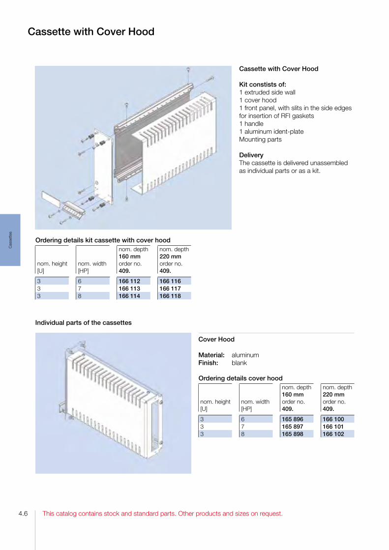
This catalog contains stock and standard parts. Other products and sizes on request.4.6
Cas
sett
es
Cassette with Cover Hood
Kit constists of:1 extruded side wall1 cover hood1 front panel, with slits in the side edges for insertion of RFI gaskets1 handle1 aluminum identplateMounting parts
DeliveryThe cassette is delivered unassembled as individual parts or as a kit.
Cassette with Cover Hood
Cover Hood
Material: aluminumFinish: blank
Individual parts of the cassettes
Ordering details kit cassette with cover hood
nom. height [U]
nom. width [HP]
nom. depth 160 mm order no. 409.
nom. depth 220 mm order no. 409.
3 6 166 112 166 1163 7 166 113 166 1173 8 166 114 166 118
Ordering details cover hood
nom. height [U]
nom. width [HP]
nom. depth 160 mm order no. 409.
nom. depth 220 mm order no. 409.
3 6 165 896 166 1003 7 165 897 166 1013 8 165 898 166 102
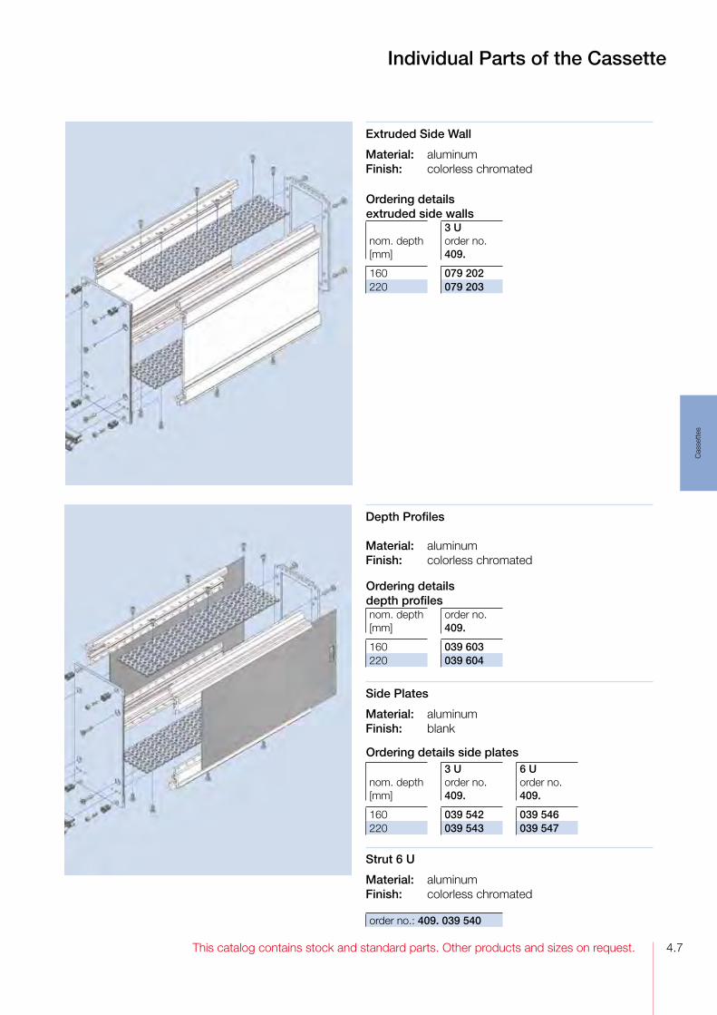
4.7This catalog contains stock and standard parts. Other products and sizes on request.
Cas
sett
es
Individual Parts of the Cassette
Extruded Side Wall
Material: aluminumFinish: colorless chromated
Depth Profiles
Material: aluminumFinish: colorless chromated
Side Plates
Material: aluminumFinish: blank
Strut 6 U
Material: aluminumFinish: colorless chromated
order no.: 409. 039 540
Explosionszeichnung
Ordering details extruded side walls
nom. depth [mm]
3 U order no. 409.
160 079 202220 079 203
Ordering details depth profilesnom. depth [mm]
order no.409.
160 039 603220 039 604
Ordering details side plates
nom. depth [mm]
3 U order no. 409.
6 U order no. 409.
160 039 542 039 546220 039 543 039 547

This catalog contains stock and standard parts. Other products and sizes on request.4.8
Cas
sett
es
Rear Panel RG3 U panel wall closed. 6 U cassettes requiretwo 3 U rear panels.
Material: aluminumFinish: blank
Rear Panel RT3 U rear panel with partical aperture. 6 U cassettes requiretwo 3 U rear panels.
Material: aluminumFinish: blank
Rear Panel RV3 U Rear panel with full aperture. 6 U cassettes requiretwo 3 U rear panels.
Material: steelFinish: galvanized und colorless chromated
Individual Parts of the Cassettes
Ordering detailsrear panel RGnom. width [HP]
order no. 409.
8 -10 166 23712 166 23814 166 23921 166 24028 166 24142 166 242
Ordering detailsrear panel RTnom. width [HP]
order no. 409.
8 166 24310 -12 -14 -21 -28 -42 -
Ordering detailsrear panel RVnom. width [HP]
order no. 409.
8 -10 043 51412 043 51614 043 51821 043 52528 043 53242 043 546
039312
039177
043511

4.9This catalog contains stock and standard parts. Other products and sizes on request.
Cas
sett
es
Individual Parts of the Cassettes
Front Panel For cassette with extruded side panel or depth profiles.
Material: aluminumFinish: front anodized, rear and edges blank
Top/Bottom Plate
Material: steelFinish: galvanized and colorless chromated
040145
Front Panel For cassette with cover hood.
Material: aluminumFinish: front anodized, rear and edges blank
Ordering details top/bottom plate
nom. width [HP]
nom. depth 160 mm order no. 409.
nom. depth 220 mm order no. 409.
8 038 687 038 76310 038 689 038 76512 038 691 038 76714 038 693 038 76921 038 700 038 77628 038 707 038 78342 038 721 038 797
Ordering details front panel for cassette
nom. width [HP]
3 U order no. 409.
6 Uorder no. 409.
8 115 005 119 02410 115 007 119 02612 115 009 119 02814 115 011 119 03021 115 018 119 03728 115 025 119 04442 115 039 119 058
Ordering details front panel for cassette cover hood
nom. width [HP]
3 U order no. 409.
6 122 3807 120 2828 120 283

This catalog contains stock and standard parts. Other products and sizes on request.4.10
Cas
sett
es
Individual Parts of the Cassettes
Handle FP for Front PanelsAssembled with M 2.5 screws and with 1 additional self tapping screw from 6 HP. The handle is held against torsion by means of two nipples.
Ident-Platefor handle FP.The identplate is markable and printable, snapped in after mounting the handle to the front panel.
Material: aluminum Finish: anodized
022 722
058 719
Ordering details handle FP
width [HP]
length [mm]
gray order no.409.
black order no.409.
6 29.04 103 006 103 206 7 34.12 103 007 103 207 8 39.20 103 008 103 208
Ordering details handle strip FP
width [HP]
length [mm]
gray order no. 409.
black order no. 409.
10 49.36 103 810 058 91012 59.52 103 812 058 91214 69.68 103 814 058 91421 105.24 103 821 058 92128 150.80 103 828 058 92842 211.92 103 842 058 942
Ordering details ident-plate
width [HP]
length [mm]
order no.409.
6 29.04 022 792 7 34.12 022 793 8 39.20 022 79410 49.36 022 79612 59.52 022 79814 69.86 022 80021 105.24 022 80728 150.80 022 81442 211.92 040 652
Technical data
MaterialPolycarbonate, colored10% fiberglass reinforced
Color gray RAL 7032, black
Continous temperature – 40 °C to + 100 °C)
Fire protection class UL 94 V–0
Mounting parts for handles: Minimum order quantity each 100 pieces
order no. 409.
Washer 2.7 013 911Self tapping screw M 2.5 x 10 040 401
Mounting parts of the cassetteMinimum order quantity each 100 pieces
order no.409.
To assemble the strut and the top/bottom plates to the profiles
Oval head screw M 2.5 x 5 039 691To assemble the rear plate to the profiles
Oval head screw M 3 x 12 108 963Spring washer A 3 040 969
To assemble the front panel to the profiles
Counter sunk screw M 3 x 12 108 962To assemble the cassette into the subrack
Screw retainer 2.5, gray 100 539Screw M 2.5 x 11.3 101 917
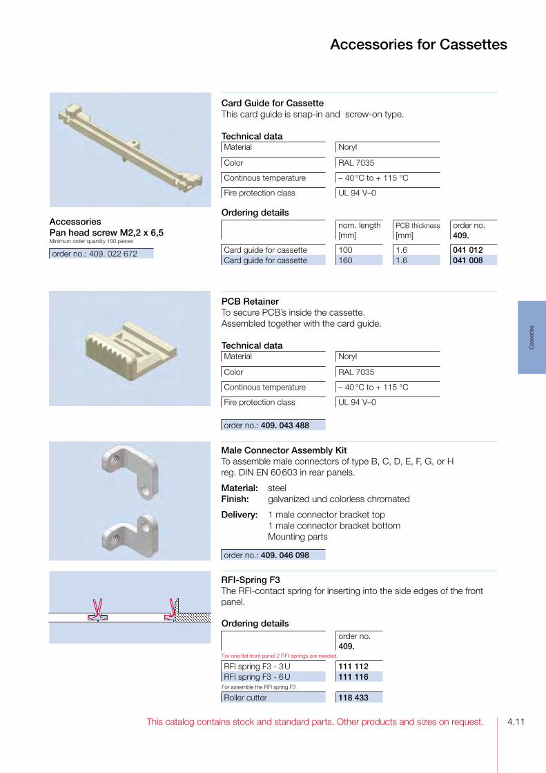
4.11This catalog contains stock and standard parts. Other products and sizes on request.
Cas
sett
es
Accessories for Cassettes
AccessoriesPan head screw M2,2 x 6,5Minimum order quantity 100 pieces
order no.: 409. 022 672
Male Connector Assembly KitTo assemble male connectors of type B, C, D, E, F, G, or H reg. DIN EN 60 603 in rear panels.
Material: steelFinish: galvanized und colorless chromated
Delivery: 1 male connector bracket top 1 male connector bracket bottom Mounting parts
RFI-Spring F3The RFIcontact spring for inserting into the side edges of the front panel.
Card Guide for CassetteThis card guide is snapin and screwon type.
Technical dataMaterial Noryl
Color RAL 7035
Continous temperature – 40 °C to + 115 °C
Fire protection class UL 94 V–0
Ordering detailsnom. length [mm]
PCB thickness [mm]
order no. 409.
Card guide for cassette 100 1.6 041 012Card guide for cassette 160 1.6 041 008
order no.: 409. 043 488
PCB RetainerTo secure PCB’s inside the cassette. Assembled together with the card guide.
Technical dataMaterial Noryl
Color RAL 7035
Continous temperature – 40 °C to + 115 °C
Fire protection class UL 94 V–0
order no.: 409. 046 098
Ordering details order no. 409.
For one flat front panel 2 RFIsprings are needed.
RFI spring F3 3 U 111 112RFI spring F3 6 U 111 116
For assemble the RFI spring F3
Roller cutter 118 433

This catalog contains stock and standard parts. Other products and sizes on request.4.12
Cas
sett
es
Accessories for Cassettes
Mounting BlockTo connect top/bottom plate with rear panel.The mounting block can also be used to enhance RFI shielding in conjunction with blank rear panel RG. The rear panel can be additionally drilled for extra contact points.
Backplane HolderTo assemble backplanes on top/bottom plate.
Cassette AngleTo assembly a free wiring level inside of the cassette.Mounted on the top/bottom plate.
Material: steelFinish: galvanized and colorless chromated
039850
order no.: 409. 044 090
order no.: 409. 119 013
Ordering details cassette angle
length[mm]
for cassette nom. width [HP]
order no. 409.
9.18 8 039 851 19.34 10 039 853 29.50 12 039 855 39.66 14 039 857 75.22 21 039 864110.78 28 039 954181.90 42 039 968
AccessoriesMinimum order quantity each 100 pieces
order no.409.
To assemble the rear plate and the backplane holder at the top/bottom plates
Oval head screw M 2.5 x 6 046 999To assemble the backplane or the rear panel at the mounting block or backplane holder
Oval head screw Taptite M 2.5 x 10 040 401Spring washer 2.7 013 911
AccessoriesMinimum order quantity each 100 pieces
order no.409.
To assemble the casssette angle at the top/bottom plates
Oval head screw M 2.5 x 5 039 691To assemble the connectors at the cassette angle
Tapered screw M 2.5 x 6.5 032 708

4.13This catalog contains stock and standard parts. Other products and sizes on request.
Cas
sett
es
ShellTo cover the open space between the top and bottom rear panels for 6Ucassette. The shell is assembled at the strut.
Material: aluminumFinish: colorless chromated
AccessoriesOval head screw M 3 x 12Minimum order quantity 100 pieces
order no.: 409. 108 963
040346
Accessories for Cassettes
Ordering detailsnom. width [HP]
order no. 409.
Shell 08 8 040 348Shell 10 10 040 350Shell 12 12 040 352Shell 14 14 040 354Shell 21 21 040 361Shell 28 28 040 368Shell 42 42 040 382
Screw M 2.5 x 11.3 for 2.5 mm thick Front panels
Material: Knurled head screw: steel nickel plated Others: stainless steel
Grounding Bushing M 2.5To press in to the front panel in order to get electrical bounding to the cassette even when the front panel is anodized.
Material: brass, nickel platedMinimum order quantity 10 pieces order no.: 409. 082 594
Technical dataMaterial POM
Color gray or black
Continous temperature – 40 °C to + 100 °C
Ordering details Minimum order quantity 100 pieces
Colororder no. 409.
Screw retainer 2.5 M 2.5 gray 100 539Screw retainer 2.5 M 2.5 black 100 538
Screw retainer 2.5 - M 2.5To 2.5 mm thickness front panels, for pushing in the screw
Ordering details Minimum order quantity 100 pieces
head formorder no. 409.
Pan head screw sloted 100 540Oval head screw cross slot 101 917Knurled head screw knurled 101 918
Screw retainer, grounding bushing and screw
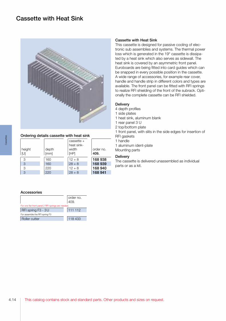
This catalog contains stock and standard parts. Other products and sizes on request.4.14
Cas
sett
es
Cassette with Heat Sink
Cassette with Heat Sink This cassette is designed for passive cooling of electronic sub assemblies and systems. The thermal power loss which is generated in the 19“ cassette is dissipated by a heat sink which also serves as sidewall. The heat sink is covered by an asymmetric front panel. Euroboards are being fitted into card guides which can be snapped in every possible position in the cassette. A wide range of accessories, for example rear cover, handle and handle strip in different colors and types are available. The front panel can be fitted with RFI springs to realize RFI shielding of the front of the subrack. Optionally the complete cassette can be RFI shielded.
Delivery4 depth profiles1 side plates 1 heat sink, aluminum blank1 rear panel 3 U 2 top/bottom plate1 front panel, with slits in the side edges for insertion of RFI gaskets1 handle1 aluminum identplateMounting parts
DeliveryThe cassette is delivered unassembled as individual parts or as a kit.
Ordering details cassette with heat sink
height [U]
depth [mm]
cassette + heat sinkwidth[HP]
order no. 409.
3 160 12 + 8 168 938 3 160 28 + 8 168 939 3 220 12 + 8 168 940 3 220 28 + 8 168 941
Accessoriesorder no. 409.
For one flat front panel 2 RFIsprings are needed.
RFI spring F3 3 U 111 112For assemble the RFI spring F3
Roller cutter 118 433
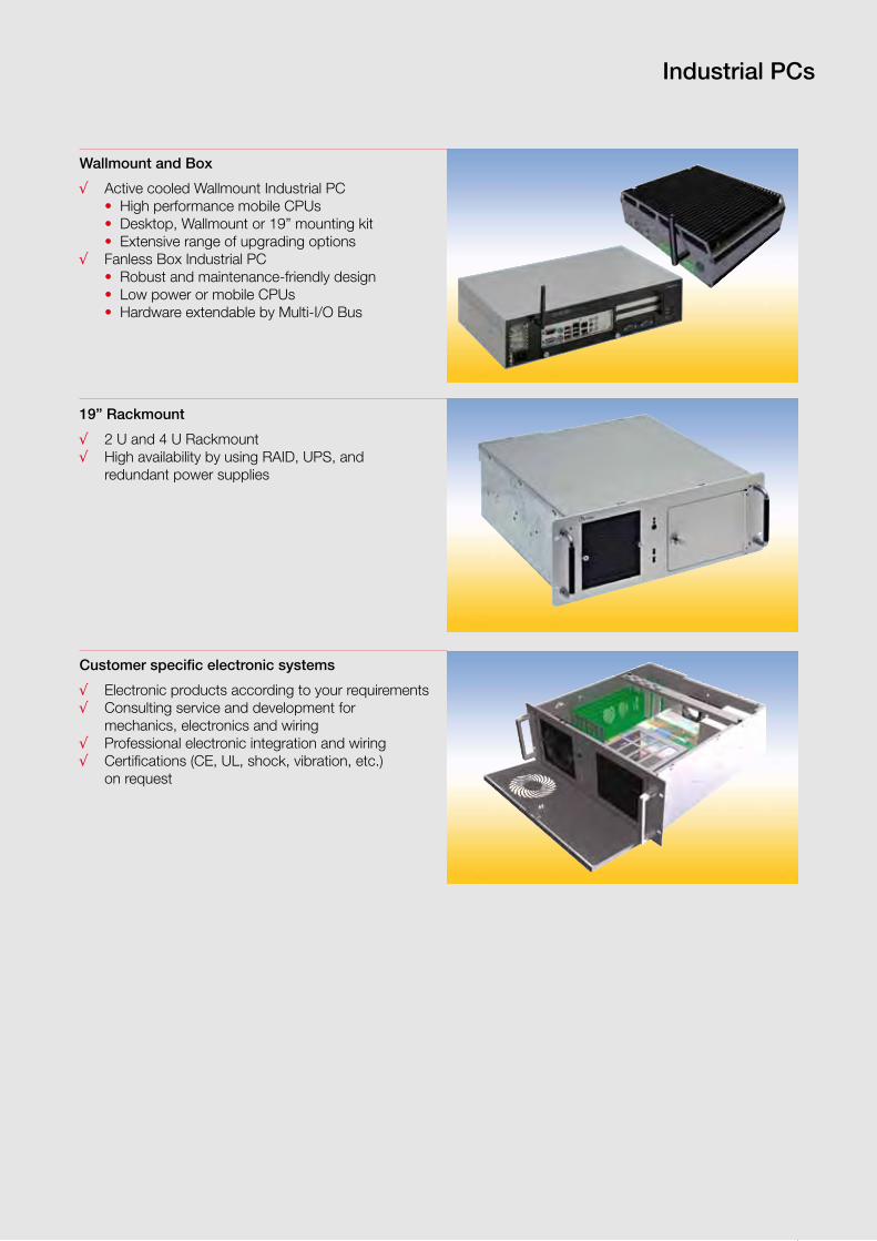
5.1
Indu
stria
l PC
s
This catalog contains stock and standard parts. Other products and sizes on request.
Industrial PCs
Customer specific electronic systems
√ Electronic products according to your requirements √ Consulting service and development for mechanics, electronics and wiring√ Professional electronic integration and wiring√ Certifications (CE, UL, shock, vibration, etc.) on request
Wallmount and Box
√ Active cooled Wallmount Industrial PC • High performance mobile CPUs • Desktop, Wallmount or 19” mounting kit • Extensive range of upgrading options√ Fanless Box Industrial PC • Robust and maintenance-friendly design • Low power or mobile CPUs • Hardware extendable by Multi-I/O Bus
19” Rackmount
√ 2 U and 4 U Rackmount√ High availability by using RAID, UPS, and redundant power supplies

5.2
Indu
stria
l PC
s
This catalog contains stock and standard parts. Other products and sizes on request.
Wallmount Industrial PC
Description
The Intermas WM-M is a robust and long term available Wallmount Industrial PC. It has a compact and modular design and allows various technical and mechanical extensions.
Advantages
√ Robust and maintenance-friendly housing√ Only long term available components√ Overpressure-based cooling concept with active ventilation√ Expansion slots via riser card√ Two hard disks with RAID 0 or RAID 1√ Hard drive bay with 2 x 2.5“ operated from outside√ I/O plate for customer specific ports√ All operating elements and connections at the device front√ Assembly: 3 U 19” Rackmount, Wallmount, desktop housing√ Air filter easily replaceable from outside√ WLAN IEEE 802.11b/g/n (Draft 2.0), 144Mbps
Application
√ Measurement and control√ Visualization√ Data logging and conversion√ Image and video data processing√ Soft-SPS IEC 61131
General
• All components designed for 24/7 operation• 5 – 50 °C operating temperature range• Extensive test of all components including Burn-In test
Optional components
• Optical disk drive DVD-ROM or DVD-RW• Up to 16 GB DDR3 SODIMM • Additional hard drive 2.5”• Compact Flash• WLAN: 144Mbps module incl. antenna• 19” 3 U mounting flanges
Technical data
Housing
Dimension (HxWxD): 100 x 410 x 230 mmWeight: about 5 kgMaterial: fire-galvanized steel plate housing, top cover and base plate painted aluminium
Power supply
1 U power supply 180-250 W Input: 90-264 VAC, 47-63 Hz, active PFC
Mainboard Kontron KTQM67Mobile Intel® QM67 Express chip set
Memory /Storage
2 GB DDR3 SODIMM2.5” HDD, Hitachi Travelstar 250 GB
CPU
FCPGA988, embedded Intel® Core™ i7 – 2xxx prozessor series Intel® Core™ i5 – 2xxx prozessor series Intel® Celeron® prozessor B810
Interface
6 x SATA (incl. 2 x SATAIII), RAID support USB 2.0: 6 x external, 8 x internal LAN: 3 x Intel® GB 4 x COM1 x PCI-Express x16, 1 x PCI-Express Grafic: 2 x Display Port, LVDS and DVI

5.3
Indu
stria
l PC
s
This catalog contains stock and standard parts. Other products and sizes on request.
Box Industrial PC
Description
The Intermas CB-M is a robust and long term available Box Industrial PC. It has a compact and modular design, based on Intermas DiVar profiles. This construction method allows high flexibility of the case geometry in all three axes.
Advantages
√ Robust and maintenance-friendly housing√ Only long term available components√ Passive cooling system√ No rotating components with CFast card√ 8 GPIO ports√ Extendable hardware via MI/O (Multiple I/O) extension√ All operating elements and connectors at the device front√ WLAN IEEE 802.11b/g/n (Draft 2.0), 144Mbps
Application
√ Measurement and control√ Visualization√ Data logging and conversion√ Image and video data processing√ Soft-SPS IEC 61131
General
• All components designed for 24/7 operation• 5 – 40 °C operating temperature range• Extensive test of all components including Burn-In test
Optional components
• Wall mounting brackets• 4 GB DDR3 SODIMM • Additional hard drive 2.5”• CFast Flash card• WLAN: 144Mbps module incl. antenna
Technical data
HousingDimension (HxWxD): 83 x 262 x 215 mmWeight: about 4 kgMaterial: aluminium anodized / painted
Power supply
Wide-range input 10…36 .DC Operating temperature range -20…+70 °C
Mainboard Advantech MIO-5270D-S6A1EAMD G-Series + A50M FCH
Memory /Storage
1 GB DDR3 SODIMM2.5” HDD, Hitachi Travelstar 250 GB
CPU
AMD Embedded-G series T40R 1.0GHz Single CoreT40E 1.0GHz Dual CoreT44R 1.2GHz Single CoreT56N 1.65GHz Dual Core
Interface
2 x SATA, 1 x CFast USB 2.0: 4 x external, 2 x internal 2 x GBit LAN, Realtec RTL8111E4 x COM Graphic: LVDS, VGA and DVI, Dual Display 1 x PCIe Mini Card, 1 x MIOe

5.4
Indu
stria
l PC
s
This catalog contains stock and standard parts. Other products and sizes on request.
19” 4 U Rackmount Industrial PC
Description
The Intermas RM-4 is a robust and long term available 19” 4 U Rackmount Industrial PC. Its robust and scalable chassis has an excellent mechanical stability, which makes the RM-4 suitable for use in harsh indu-strial environments.
Advantages
√ Robust and maintenance-friendly housing√ Only long term available components√ Overpressure-based cooling concept with active ventilation√ 7 slots with variable hold-down brackets√ All operating elements and two USB-ports at the device front√ Optional assembly of telescopic rails√ Air filter for front-sided ventilation easily replaceable from outside √ WLAN IEEE 802.11b/g/n (Draft 2.0), 144Mbps√ TEAC 3.5” card reader
Application
√ Measurement and control√ Visualization√ Data logging and conversion√ Image and video data processing√ Data recording and archiving√ Soft-SPS IEC 61131
General
• All components designed for 24/7 operation• 5 – 50 °C operating temperature range• Extensive test of all components including Burn-In test
Optional components
• Optical disk drive DVD-ROM or DVD-RW• Up to 32 GB DDR3 SDRAM• Up to 5 hard disks 3.5”• Hard drives in RAID 0/1/5/10 configuration• 3.5” card reader• WLAN: 144Mbps module incl. antenna• Hold down brackets for plug-in cards• Telescopic rails
Technical data
Housing
Dimension (HxWxD): 177 ( 4 U) x 483 (19”) x 448 mmWeight: about 15 kgMaterial: fire-galvanized steel plate housing, front plate painted aluminium
Power supply
Bicker BEA 630, 300 WInput voltage 90…264 VAC, 47-63 Hz, active PFC4-kV-surge-input filter
Mainboard Fujitsu D3076-S ATXIntel® Q67 Express chip set
Memory /Storage
2 GB DDR3 SDRAM3.5” HDD, Hitachi Deskstar 320 GB
CPU
LGA 1155, embedded Intel® Core™ i7 – 2xxx prozessor series Intel® Core™ i5 – 2xxx prozessor series Intel® Core™ i3 – 2xxx prozessor series
Interface
6 x SATA (incl. 2 x SATAIII), RAID =0/1/5/10 support USB 2.0: 8 x external, 2 x internal 2 x GBit LAN, Intel 82579LM / Intel 82574L2 x COM Intel® HD Graphics DX10.1, DVI-I / DisplayPort4 x PCI, 2 x PCI-Express x16

5.5
Indu
stria
l PC
s
This catalog contains stock and standard parts. Other products and sizes on request.
Description
The Intermas RM-2 is a robust and long term available 19” 2 U Rackmount Industrial PC. Its robust and scalable chassis has an excellent mechanical stability, which makes the RM-2 suitable for use in harsh industrial environments.
Advantages
√ Robust and maintenance-friendly housing√ Only long term available components√ Overpressure-based cooling concept with active ventilation√ Two slots via riser card √ All operating elements and two USB-ports at the device front√ Optional assembly of telescopic rails√ Air filter for front-sided ventilation easily replaceable from outside√ WLAN IEEE 802.11b/g/n (Draft 2.0), 144Mbps√ TEAC 3,5” card reader
General
• All components designed for 24/7 operation• 5 – 50 °C operating temperature range• Extensive test of all components including Burn-In test
Technical data
Housing
Dimension (HxWxD): 88 (2 U) x 483 (19”) x 443 mmWeight: about 12 kgMaterial: fire-galvanized steel plate housing, front plate painted aluminium
Power supply
2 U ATX power supply, 300 WInput voltage 90…264 VAC, 47-63 Hz, active PFC
Mainboard Fujitsu D3071-S µATXIntel® Q67 Express chip set
Memory /Storage
2 GB DDR3 SDRAM3.5” HDD, Hitachi Deskstar 320 GB
CPU
LGA 1155, embedded Intel® Core™ i7 – 2xxx prozessor series Intel® Core™ i5 – 2xxx prozessor series Intel® Core™ i3 – 2xxx prozessor series
Interface
6 x SATA (incl. 2 x SATAIII), RAID =0/1/5/10 support USB 2.0: 8 x external, 2 x internal2 x GBit LAN, Intel 82579LM / Intel 82574L2 x COM Intel® HD Graphics DX10.1, DVI-I / DisplayPort2 x PCI, 2 x PCI-Express x16
Application
√ Measurement and control√ Visualization√ Data logging and conversion√ Image and video data processing√ Data recording and archiving√ Soft-SPS IEC 61131
Optional components
• Optical disk drive DVD-ROM or DVD-RW• Up to 32 GB DDR3 SDRAM• Up to 3 hard disks 3.5”• Hard drives in RAID 0/1 configuration• 3.5” card reader• WLAN: 144Mbps module incl. antenna• Telescopic rails
19” 2 U Rackmount Industrial PC

5.6
Indu
stria
l PC
s
This catalog contains stock and standard parts. Other products and sizes on request.
Customer specific electronic systems
Please ask your local representative for yourindividual system configuration.
You find your contact person on our homepage: www.intermas-el.com
System consulting √ Project planning combining your specifications and our know-howDevelopment√ Mechanics, customer specific electronics, prototype construction√ Consider environmental conditions like shock, vibration, temperature and RF-signals
Highly available Industrial PC
• Lockable front door to prevent unauthorized access• System with shock and vibration dampers• High reliability by using RAID and redundant power supply
Production √ Metal processing, surface refinement, assembly
Elektronics and wiring √ ESD compliant electronic assembly and wiring Quality assurance √ Electrical safety tests, component test, system test, Burn-In
Application examples
High speed data acquisition system
• Customer specific design with PCI slots at front side• High EMI requirements because of high frequency clocking • Optimized cooling for high-quality components
Control system with touch operation
• 2,5 U height and only 6 cm depth• High performance in a small housing• Development of a cooling concept• Reliable touch operation

This catalog contains stock and standard parts. Other products and sizes on request.
Pow
er S
uppl
ies
6.1
Power Supplies
AC/DC converters with active PFC
√ VP 80√ VP 150
AC/DC converters
√ PK MONOVOLT √ PK BIVOLT √ PK TRIVOLT√ VP 40√ VP 50
AC/DC converters economy
√ EC MONOVOLT√ EC TRIVOLT
DC/DC converters
√ GK TRIVOLT

This catalog contains stock and standard parts. Other products and sizes on request.
Pow
er S
uppl
ies
6.2
Power Supplies PK-Series MONOVOLT
MONOVOLT AC/DC-converters30 to 120 Watt switched mode AC/DC plug-in power supplies with one output in 3 U Eurocassettes for use in 19” subracks to IEC 60297-3.
√ Compact rugged design in stable aluminum cassette√ High regulation accuracy√ Remote On/Off and Powerfail signal√ SENSE-operation and Overvoltage protection (OVP)√ PK 60-R for redundant operation√ Convection cooling√ CE marked for compliance to EMC and Low Voltage Directives√ Safety according to EN 60950, UL, cUL√ VERO standardised pinning√ 24 months warranty
Accessories
order no.
Reduced height front panel for PK 30 148-011002DReduced height front panel for PK 60 148-010021EReduced height front panel for PK 120 148-010019GMale connector with coding strip H15 DIN 41612 017-010115KMinimum order quantity 1 pack (10 pieces)
Coding strip 017-010064F
Ordering details Power Supplies Monovolt AC/DC-converter
nom. height/nom. width[U] / [HP]
fornom. depth[mm]
single output[W]
output[V]/ [A]
without powerfailorder no. 116.
PK 30 3 / 8 >160 30 5V/6A 010016D*PK 60 3 / 8 >160 60 5V/12A 010063D*PK 60 3 / 8 >160 60 12V/5A 010064A*PK 60 3 / 8 >160 60 24V/2,5A 010066F*PK 120 3 / 14 >160 120 12V/10A 010070JPK 120 3 / 14 >160 120 24V/5A 010072C
* EN 60950, UL and cUL certified
For applications according EN 61000-3-2, we recommend the VP-Series.

This catalog contains stock and standard parts. Other products and sizes on request.
Pow
er S
uppl
ies
6.3
Power Supplies PK-Series MONOVOLT
Technical input dataInput voltage (switchable) 115 / 230VACInput frequency 47-63HzInrush surge current limit by NTCInput voltage spike limit by VDRHold-up time >20 msec (at nominal values)Efficiency typ. > 80%Safety: CE marking according tolow voltage directive 73/23/EEGSafety according to EN 60950, UL 1950EMC: CE marking according EMC directive 89/336/EEGEMI conducted & radiated emission EN 55022/B (0.15-30MHz; 30-1000MHz)EMI immunity EN 50082-2Operating temperature / Storage temperature 0 °C...+70 °C / -25 °C...+85 °CRelative humidity max. 95% without condensation
Case material / finishclear anodised aluminum cassette with cooling cutouts
Technical data: output voltagePK 30
V1PK 60
V1PK 60
V1PK 60
V1PK 120
V1PK 120
V1
Single output 30 W 60 W 60 W 60 W 120 W 120 W
Output voltage 5V 5V 12V 24V 12V 24V
Adjustment range 4.85-5.5V 4.5-5.5V 11-13V 22-26V 10.8-13.2V 21.6-26.4V
Output nominal current 6A 12A 5A 2,5A 10A 5A
Ripple at full load <40mVPP
<40mVPP
<40mVPP
<40mVPP
<40mVPP
<40mVPP
Line regulation (100% IOUT)
<0.2% <0.3% <0.2% <0.2% <0.2% <0.2%
Load regulation static (10...90%IOUT)
<0.2% <0.2% <0.2% <0.2% <0.2% <0.2%
Response time (10...90%IOUT)
<1ms <0.8ms <0.5ms <0.5ms <0.5ms <0.5ms
Output current limit >6.5A >12.5A >5.3A >2.7A >11A >5.5A
Short circuit protection continously, automatic restart
Overvoltage protection (OVP)
6-6.7V5.5-6.0V
adjustable
13.2-15V
adjustable
26.4-30V
adjustable
12-16.5V
adjustable
27-29V
adjustable
Powerfail signal (at full load >6ms)
— V1<4.8V — V1<23V >11.5V >23.0V
Temperature coefficient 0.02%/°C 0.02%/°C 0.02%/°C 0.02%/°C 0.02%/°C 0.02%/°C
Output regulation with sense
0.5V max. 0.5V max. 0.5V max. 0.5V max. 0.5V max. 0.5V max.
Derating1 W/°C
above 55°C
1.6 W/°C
above 45°C
1.6 W/°C
above 45°C
1.6 W/°C
above 45°C
2.4 W/°C
above 55°C
2.4 W/°C
above 55°C
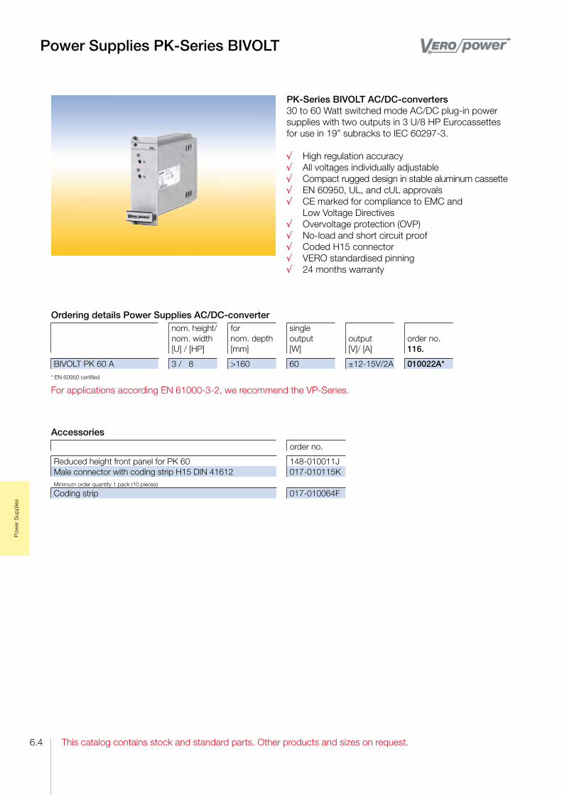
This catalog contains stock and standard parts. Other products and sizes on request.
Pow
er S
uppl
ies
6.4
Power Supplies PK-Series BIVOLT
PK-Series BIVOLT AC/DC-converters 30 to 60 Watt switched mode AC/DC plug-in power supplies with two outputs in 3 U/8 HP Eurocassettes for use in 19” subracks to IEC 60297-3.
√ High regulation accuracy√ All voltages individually adjustable√ Compact rugged design in stable aluminum cassette√ EN 60950, UL, and cUL approvals√ CE marked for compliance to EMC and Low Voltage Directives√ Overvoltage protection (OVP)√ No-load and short circuit proof√ Coded H15 connector√ VERO standardised pinning√ 24 months warranty
Accessories
order no.
Reduced height front panel for PK 60 148-010011JMale connector with coding strip H15 DIN 41612 017-010115KMinimum order quantity 1 pack (10 pieces)
Coding strip 017-010064F
Ordering details Power Supplies AC/DC-converternom. height/nom. width[U] / [HP]
fornom. depth[mm]
single output[W]
output[V]/ [A]
order no. 116.
BIVOLT PK 60 A 3 / 8 >160 60 ±12-15V/2A 010022A** EN 60950 certified
For applications according EN 61000-3-2, we recommend the VP-Series.

This catalog contains stock and standard parts. Other products and sizes on request.
Pow
er S
uppl
ies
6.5
Power Supplies PK-Series BIVOLT
Technical data: output voltagePK 60 A V1, V2
Dual output 60 W
Output voltage ±12-15V
Adjustment range ±12-15V
Output nominal current 2A, 2A
Ripple at full load <20mVPP
Line regulation (100% IOUT) <0.2%
Load regulation static (10...90%IOUT) <0.5%
Response time (10...90%IOUT) <1ms
Output current limit >2.2A
Short circuit protectioncontinously,
automatic restart
Overvoltage protection (OVP) fix ±16.5-19V
Powerfail-Signal (at full load>6ms) >4.8V
Temperature coefficient 0.02%/°C
Derating1.6 W/°C above
55°C
Technical input dataInput voltage (switchable) 94-253VACInput frequency 47-63HzInrush surge current limit by NTCInput voltage spike limit by VDRHold-up time >20 msec (at nominal values)Efficiency typ. > 80%Safety: CE marking according tolow voltage directive 73/23/EEGSafety according to EN 60950, UL 1950EMC: CE marking according EMC directive 89/336/EEGEMI conducted & radiated emission EN 55022/B (0.15-30MHz; 30-1000MHz)EMI immunity EN 50082-2Operating temperature / Storage temperature 0 °C...+70 °C / -25 °C...+85 °CRelative humidity max. 95% without condensation
Case material / finishclear anodised aluminum cassette with cooling cutouts:
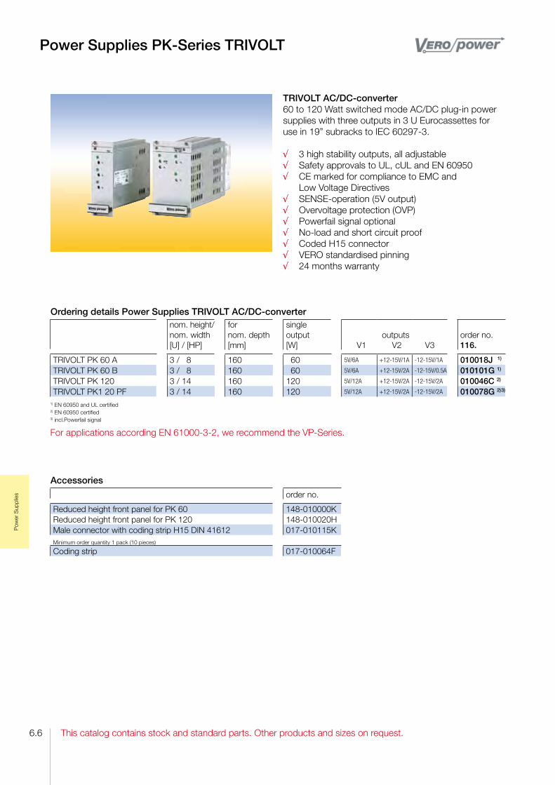
This catalog contains stock and standard parts. Other products and sizes on request.
Pow
er S
uppl
ies
6.6
Power Supplies PK-Series TRIVOLT
TRIVOLT AC/DC-converter60 to 120 Watt switched mode AC/DC plug-in power supplies with three outputs in 3 U Eurocassettes for use in 19” subracks to IEC 60297-3.
√ 3 high stability outputs, all adjustable√ Safety approvals to UL, cUL and EN 60950√ CE marked for compliance to EMC and Low Voltage Directives√ SENSE-operation (5V output)√ Overvoltage protection (OVP)√ Powerfail signal optional√ No-load and short circuit proof√ Coded H15 connector√ VERO standardised pinning√ 24 months warranty
Ordering details Power Supplies TRIVOLT AC/DC-converternom. height/nom. width[U] / [HP]
fornom. depth[mm]
single output[W]
outputsV1 V2 V3
order no. 116.
TRIVOLT PK 60 A 3 / 8 160 60 5V/6A +12-15V/1A -12-15V/1A 010018J 1)
TRIVOLT PK 60 B 3 / 8 160 60 5V/6A +12-15V/2A -12-15V/0.5A 010101G 1)
TRIVOLT PK 120 3 / 14 160 120 5V/12A +12-15V/2A -12-15V/2A 010046C 2)
TRIVOLT PK1 20 PF 3 / 14 160 120 5V/12A +12-15V/2A -12-15V/2A 010078G 2) 3)
1) EN 60950 and UL certified2) EN 60950 certified3) incl.Powerfail signal
For applications according EN 61000-3-2, we recommend the VP-Series.
Accessories
order no.
Reduced height front panel for PK 60 148-010000KReduced height front panel for PK 120 148-010020HMale connector with coding strip H15 DIN 41612 017-010115KMinimum order quantity 1 pack (10 pieces)
Coding strip 017-010064F

This catalog contains stock and standard parts. Other products and sizes on request.
Pow
er S
uppl
ies
6.7
Power Supplies PK-Series TRIVOLT
Technical input dataInput voltage (switchable) 94-253VACInput frequency 47-63HzInrush surge current limit by NTCInput voltage spike limit by VDRHold-up time >20 msec (at nominal values)Efficiency typ. >75%Safety: CE marking according tolow voltage directive 73/23/EEGSafety according to EN 60950, UL 1950EMC: CE marking according EMC directive 89/336/EEGEMI conducted & radiated emission EN 55022/B (0.15-30MHz; 30-1000MHz)EMI immunity EN 50082-2Operating temperature / Storage temperature 0 °C...+70 °C / -25 °C...+85 °CRelative humidity max. 95% without condensationCase material / finish clear anodised aluminum cassette with cooling cutouts
Technical data: output voltagePK 60 A
V1 V2 V3PK 60 B
V1 V2 V3PK 120 / PK 120 PFV1 V2 V3
Triple-output 60 W 60 W 120 W
Output voltage 5V +12V -12V 5V +12V -12V 5V +12V -12V
Adjustment range 4.5-5.5V +12-15V -12-15V 4.5-5.5V +12-15V -12-15V 4.5-5.5V +12-15V -12-15V
Output nominal current 6A 1A 1A 6A 2A 0.5A 12A 2A 2A
Ripple at full load <40mVPP
<3mVPP
<3mVPP
<40mVPP
<3mVPP
<3mVPP
<40mVPP
<20mVPP
<20mVPP
Line regulation (100% IOUT) <0.2% <0.02% <0.02% <0.2% <0.02% <0.02% <0.2% <0.02% <0.02%
Load regulation static (10...90%IOUT)
<0.2% <0.2% <0.2% <0.5% <0.5% <0.5% <0.2% <0.2% <0.2%
Response time (10...90%IOUT)
<1ms <10µs <10µs <1ms <10µs <10µs <0.2ms <0.5ms <0.5ms
Output current limit >6.5A >1.1A >1.1A >6.5A >2.1A >0.6A >12.5A >2.2A >2.2A
Short circuit protection continously, automatic restart
Overvoltage protection (OVP)
6.0-6.7V - - 6.0-6.7V - -+5.5-6.0V
adjustable
+16.5-19V
fix
-16.5-19V
fix
Powerfail signal (at full load >6ms)
<4.8V - - <4.8V - - >4.8V - -
Temperature coefficient 0.02%/°C 0.02%/°C 0.02%/°C
Output regulation with sense 0.5V max. - - 0.5V max. - - 0.5V max. - -
Derating 1.6 W/°C above 55°C 1.6 W/°C above 55°C 4 W/°C above 55°C

This catalog contains stock and standard parts. Other products and sizes on request.
Pow
er S
uppl
ies
6.8
Power Supplies VP-Series, 40 and 50 1 - 3 Outputs
AC/DC-converter40 or 50 Watt switched mode AC/DC plug-in power supplies in 3 U/4 HP Eurocassettes for use in 19” subracks to IEC 60297-3.
√ Wide input range 94-253VAC√ High efficiency from 75% to 84% √ CE marking according EMI and LV directive√ Safety according to EN 60950, UL, cUL√ Optional: EMI frontpanel, no frontpanel√ VERO standard pinning, suits to PK 60√ SENSE-operation√ Convection cooling√ 24 months warranty
Accessories
order no.
Male connector with coding strip H15 DIN 41612 017-010115KMinimum order quantity 1 pack (10 pieces)
Coding strip 017-010064F
With modern switch mode technology VP 40 achieves an efficiency up to 75%, VP 50 up to 84%.
Ordering details Power Supplies AC/DC-converter
nom.height/nom. width[U] / [HP]
fornom. depth[mm]
output[W]
outputs
with front plate order no. 116.
VP 40-3 A 3 / 4 >160 40 5V/4A; +12…15V/0.6A; -12...-15V/0.6A 040311E*VP 40-3 B 3 / 4 >160 40 +12...15V/1.4A; +12...15V/0.6A; -12...-15V/0.6A 040312B*VP 40-3 C 3 / 4 >160 40 24V/0.8A; +12...15V/0.6A; -12...-15V/0.6A 040313K*VP 50-1 3 / 4 >160 50 5V/10A 040151K*VP 50-1 3 / 4 >160 50 12V/4.2A...15V/3.3A 040152G*VP 50-1 3 / 4 >160 50 24V/2.1A 040153D*
*) EN 60950-1 certified

This catalog contains stock and standard parts. Other products and sizes on request.
Pow
er S
uppl
ies
6.9
Power Supplies VP-Series, 40 and 50 1 - 3 Outputs
Technical input dataInput voltage 115 / 230VACInput frequency 47-63HzInrush surge current limit by NTC resistorInput voltage spike limit by VDR resistor
Hold-up time≥60 ms at 230V / ≥10 ms at 115V ≥30 ms at 230V / ≥30 ms at 115V
Powerfactor correction PFC >0,6Efficiency up to 75% / up to 85%Safety: CE marking according tolow voltage directive 2006/95/EGSafety according to EN 60950-1EMC: CE marking according EMC directive 2004/108/EG EN 61000-6-3 (2007) EN 61000-6-2 (2006)EMI conducted & radiated emission EN 55022/B (0,15-30MHz; 30-1000MHz)EMI immunity EN 50082-2Operating temperature / Storage temperature 0 °C...+70 °C / -25 °C...+85 °CRelative humidity max. 95%, not condensingDimensions (L x W x H) mm 162 x 20 x 100 mm, with front plate 128 mm
Technical data: output voltageVP 40-3 A VP 40-3 B / C VP 50-1
V1 V2 V3 V1B / C V2B / C V3B / C V1 V1 V1
Output 40 W 40 W 50 W
Output voltage +5V +12V -12V +12V +12V -12V 5V 12V 24V
Adjustment range +5V +12V...+15V -12V...-15V+12V...+15V
/ 24V+12V...+15V -12V...-15V 5V 12V...15V 24V
Output nominal current 1) 4A 0.6A 0.6A 1.4A / 0.8A 0.6A 0.6A 10A 4.2A...3.3A 2.1A
Ripple at full load ≤ 20mVss ≤ 5mVss ≤ 5mVss ≤ 20mVss ≤ 5mVss ≤ 5mVss ≤ 20mVss ≤ 40mVss ≤ 20mVss
Line regulation (100% IOUT) ≤ 0.1% ≤ 0.02% ≤ 0.02% ≤ 0.1% ≤ 0.02% ≤ 0.02% ≤ 0.1% ≤ 0.1% ≤ 0.1%
Load regulation static (10...90%IOUT)
≤ 0.1% ≤ 0.4 2) ≤ 0.4 2) ≤ 0.1% ≤ 0.4 2) ≤ 0.4 2) ≤ 0.1% ≤ 0.1 2) ≤ 0.1 2)
Response time (10...90%IOUT)
≤ 0.4ms ≤ 20µs ≤ 20µs ≤ 0.4ms ≤ 20µs ≤ 20µs ≤ 0.4ms ≤ 0.4ms ≤ 0.4ms
Output current limit > 4.2A > 0.8A > 0.8A> 1.5A
/ 0.85A> 0.8A > 0.8A > 10A 3.6A...5.5A > 2.1A
Short circuit protection yes yes yes
Overvoltage protection (OVP) 5.85V...6.25V 16.5V...18V
/26.4V...31V— — 5.85V...6.25V 16.5V...18V 16.5...31V
Powerfail signal (at full load >6ms)
≥ 5ms bevor V1< 4.8V optional optional optional optional optional optional
Output regulation with sense 0.5V max. 0.5V max. — — 0.5V max. 0.5V max. 0.5V max.
Derating 2.5% / °C, from 50 °C see derating curv
1) maximum total output power: 40 / 50 Watt, see derating 2) IOUT V1 min. 1A
Derating curve VP 40 Derating curve VP 50

This catalog contains stock and standard parts. Other products and sizes on request.
Pow
er S
uppl
ies
6.10
Power Supplies VP-Series, 80 and 150 1 - 3 Outputs
AC/DC-converter with PFC80 or 150 Watt switched mode AC/DC plug-in power supplies in 3 U/8 HP respectively 12 HP Eurocassettes for use in 19” subracks to IEC 60297-3.
√ Active Powerfactor Correction PFC√ Wide input range 94-253VAC√ High efficiency from 83% up to 87%√ Power share between outputs√ N+1 redundant types on request√ CE marking acc. EMI and LV directive√ Safety according to EN 60950, UL, cUL√ VERO standard pinning, VP 80 suits to PK 60 and VP 150 suits to PK 120√ 24 months warranty
Accessories
order no.
Male connector with coding strip H15 DIN 41612 017-010115KMinimum order quantity 1 pack (10 pieces)
Coding strip 017-010064F
With the new VP 80 /150 series an efficiency from 83% up to 87% is achieved while power density is increased over its predecessors by more than 30%. Without the need for external heatsinking, the 80 W or 150 W out-put power can be achieved with natural convection cooling. A wide range of multi O/P units is further
Ordering details Power Supplies AC/DC-converternom.height/nom. width[U] / [HP]
fornom. depth[mm]
output[W]
outputs
order no. 116.
VP 80-1 3 / 8 >120 80 24V/3.3A 020018B 1)
VP 80-3 C 3 / 8 >120 80 5V/12A; +12V/4A; -12V/1A 020026D 1)
VP 150-3 3 / 12 >120 150 5V/20A; +12V...15V/4A; -12...15V/2A 031530B 2)
1) certified to EN 60950, UL, cUL; 2) safety to EN 60950, UL, cUL
Schematic diagram VP 80 Schematic diagram VP 150
extended through power share technology, allowing maximum flexibility in the way power is delivered across the voltage rails, for smaller and more economical solutions. The range is enhanced with „Type R“ versions, designed for N+1 redundant applications or battery back-up systems.

This catalog contains stock and standard parts. Other products and sizes on request.
Pow
er S
uppl
ies
6.11
Power Supplies VP-Series, 80 and 150 1 - 3 Outputs
Technical input dataInput voltage 94-253VACInput frequency 47-63HzInrush surge current limit <27A (NTC)Input voltage spike limit by VDRHold-up time >20 msec (at nominal values)Powerfactor correction PFC >0,95 / >0,98Efficiency up to 83% / typ. >81%Safety: CE marking according tolow voltage directive 73/23/EEGSafety according to EN 60950EMC: CE marking according EMC directive 89/336/EEGEMI conducted & radiated emission EN 55022/B (0.15-30MHz; 30-1000MHz)EMI immunity EN 50082-2Operating temperature / Storage temperature 0 °C...+70 °C / -40 °C...+85 °CRelative humidity max. 90% without condensationDimensions (L x W x H) mm VP 80 162 x 32, 9 x100 mm / VP 150 162x60, 6x110 mmWeight: 650 g / 1100 g
Derating curve VP 80 Derating curve VP 150
Technical data: output voltage
VP 80-1 VP 80-3 C VP 150-3V1 V1 V2 V3 V1 V2 V3
Output 80 W 80 W 150 W
Output voltage 24V +5V +12V -12V +5V +12-15V -12-15V
Adjustment range 22-26V 4.8-5.5V fix fix 4.8...5.5V +11.8-15.2V -11.8-15.2V
Output nominal current 1) 3,3A 12A 4A 1A 20A 1) 4A 1) 2A 1)
Ripple at full load <40mVPP
<40mVPP
<40mVPP
<10mVPP
<40mVPP
<20mVPP
<20mVPP
Line regulation (100% IOUT) <0.1% <0.2% <0.2% <0.2% <0.2% <0.2% <0.2%
Load regulation static (10...90%IOUT)
<0.1% <0.5% <±4 2) <1.5% 2) <0,5% <0,2% <0,2%
Response time (10...90%IOUT)
<0.1ms <1ms <1ms <1ms <1ms <1ms <1ms
Output current limit >3.35A >12.1A >4.1A >1.01A >20.5A >5A >2.7A
Short circuit protection yes, electronic, automatic restart
Overvoltage protection (OVP) 27-32V 6.0-6.7V — — 6.0-6.5V fix +16-18V fix -16-18V fix
Powerfail signal (at full load >6ms)
V1<23V <V1-4.8V — — <V1-4.8V — —
Output regulation with sense 0.5V max. 0.5V max. — — 0.5V max. — —
Derating2 W/°C over 45°C at natural convection;
4 W/°C over 60°C at enhanced coolingsee derating curve
1) maximum total output power: 80 Watt or 150 Watt, see derating curve 2) IOUT V1 min. 1A
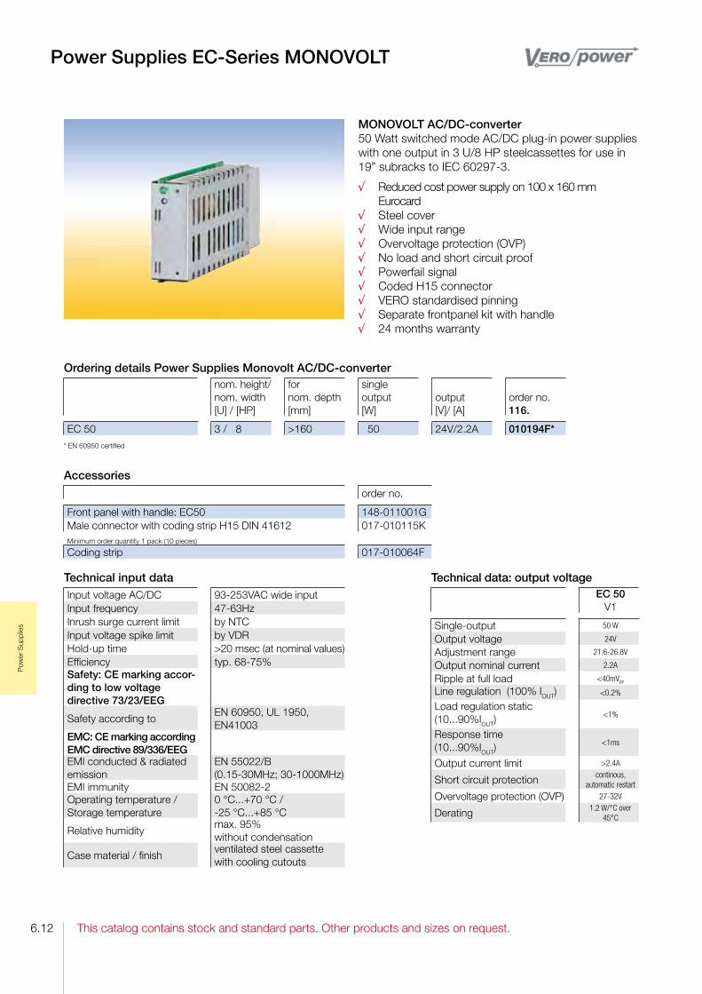
This catalog contains stock and standard parts. Other products and sizes on request.
Pow
er S
uppl
ies
6.12
Power Supplies EC-Series MONOVOLT
MONOVOLT AC/DC-converter 50 Watt switched mode AC/DC plug-in power supplies with one output in 3 U/8 HP steelcassettes for use in 19” subracks to IEC 60297-3.
√ Reduced cost power supply on 100 x 160 mm Eurocard√ Steel cover√ Wide input range√ Overvoltage protection (OVP)√ No load and short circuit proof√ Powerfail signal√ Coded H15 connector√ VERO standardised pinning√ Separate frontpanel kit with handle√ 24 months warranty
Technical input dataInput voltage AC/DC 93-253VAC wide inputInput frequency 47-63HzInrush surge current limit by NTCInput voltage spike limit by VDRHold-up time >20 msec (at nominal values)Efficiency typ. 68-75%Safety: CE marking accor-ding to low voltage directive 73/23/EEG
Safety according toEN 60950, UL 1950, EN41003
EMC: CE marking according EMC directive 89/336/EEGEMI conducted & radiated emission
EN 55022/B (0.15-30MHz; 30-1000MHz)
EMI immunity EN 50082-2Operating temperature / Storage temperature
0 °C...+70 °C / -25 °C...+85 °C
Relative humiditymax. 95% without condensation
Case material / finishventilated steel cassette with cooling cutouts
Accessories
order no.
Front panel with handle: EC50 148-011001GMale connector with coding strip H15 DIN 41612 017-010115KMinimum order quantity 1 pack (10 pieces)
Coding strip 017-010064F
Ordering details Power Supplies Monovolt AC/DC-converternom. height/nom. width[U] / [HP]
fornom. depth[mm]
single output[W]
output[V]/ [A]
order no. 116.
EC 50 3 / 8 >160 50 24V/2.2A 010194F** EN 60950 certified
Technical data: output voltageEC 50
V1
Single-output 50 W
Output voltage 24V
Adjustment range 21.6-26.8V
Output nominal current 2.2A
Ripple at full load <40mVPP
Line regulation (100% IOUT) <0.2%
Load regulation static (10...90%IOUT)
<1%
Response time (10...90%IOUT)
<1ms
Output current limit >2.4A
Short circuit protection continous, automatic restart
Overvoltage protection (OVP) 27-32V
Derating 1.2 W/°C over 45°C

This catalog contains stock and standard parts. Other products and sizes on request.
Pow
er S
uppl
ies
6.13
Power Supplies EC-Series TRIVOLT
TRIVOLT AC/DC-converter 50 Watt switched mode AC/DC plug-in power supplies with three output in 3 U steelcassettes for use in 19” subracks to IEC 60297-3.
√ Economy priced alternative of PK series√ Steel cover√ Safety according to EN 60950√ Overvoltage protection (OVP)√ No load and short circuit proof√ Powerfail signal√ Coded H15 connector√ VERO standardized pinning√ Separate frontpanel kit with handle√ 24 months warranty
Technical input dataInput voltage AC/DC 93-253VAC wide inputInput frequency 47-63HzInrush surge current limit by NTCInput voltage spike limit by VDR
Hold-up time>20 msec (at nominal values)
Efficiency typ. 70%Safety: CE marking according to low voltage directive 73/23/EEGSafety according to EN 60950, UL 1950, EMC: CE marking according EMC directive 89/336/EEGEMI conducted & radiated emission
EN 55022/B (0.15-30MHz; 30-1000MHz)
EMI immunity EN 50082-2Operating temperature / Storage temperature
0 °C...+70 °C / -25 °C...+85 °C
Relative humiditymax. 95% without conden-sation
Case material / finishventilated steel cassette with cooling cutouts
Accessories
order no.
Front panel with handle: EC50 148-011001GMale connector with coding strip H15 DIN 41612 017-010115KMinimum order quantity 1 pack (10 pieces)
Coding strip 017-010064F
Ordering details Power Supplies Monovolt AC/DC-converternom.height/nom. width[U] / [HP]
fornom. depth[mm]
output[W]
outputsV1 V2 V3
order no. 116.
EC 50 C 3 / 8 >160 50 5V/5A +15V/0.8A -15V/0.8A 010186D** EN 60950 certified
Technical data: output voltageEC 50
V1 V2 V3
Triple output 50 W
Output voltage 5V +15V -15V
Adjustment range 4.5-5.5V fix fix
Output nominal current 5A 0.8A 0.8A
Ripple at full load <40mVPP
<10mVPP
1) <10mVPP
1)
Line regulation (100% IOUT) <0.2% <0.2% <0.2%
Load regulation static (10...90%IOUT)
<1% <0.5% <0.5%
Response time (10...90%IOUT)
<1ms <1ms <1ms
Output current limit >6A(>9A2)) >1.1A >1.1A
Short circuit protection yes, electronic, automatic restart
Overvoltage protection (OVP) 6.0-6.7V — —
Powerfail-Signal (at full load>6ms)
V1<4.8V — —
Temperature coefficient 0,05%/°C
Derating 1.5 W/°C above 45°C1) V2/V3 linear post regulated 2) at single load

This catalog contains stock and standard parts. Other products and sizes on request.
Pow
er S
uppl
ies
6.14
Power Supplies GK-Series TRIVOLT
TRIVOLT DC/DC-converter 60 to 120 Watt switched mode DC/DC plug-in conver-ter with three outputs in 3 U Eurocassettes for use in 19” subracks IEC 60297-3.
√ Compact rugged design in stable aluminum cassette√ DC input range 2:1 ratio√ High regulation accuracy√ Separate adjust of all outputs√ SENSE-operation and Overvoltage protection (OVP)√ Convection cooling√ CE marked for compliance to EMC and Low Voltage Directives√ VERO standardised pinning√ 24 months warranty
Technical input dataInput voltage 24VDC (18-36)Inrush surge current limit line impedance dependantInput voltage spike limit by Thyristor-CrowbarHold-up time >3 msec (at nominal values)Efficiency typ. >70-75%Safety: CE marking according to low voltage directive 73/23/EEGSafety according to EN 60950, UL 1950, EMC: CE marking according EMC directive 89/336/EEGEMI conducted & radiated emission
EN 55022/B (0.15-30MHz; 30-1000MHz)
EMI immunity EN 50082-2Operating temperature / Storage temperature
0 °C...+70 °C / -25 °C...+85 °C
Relative humiditymax. 95% without conden-sation
Case material / finishClear anodised aluminum cassette with cooling cutouts
Accessories
order no.
Reduced height front panel GK 120 148-010020HMale connector with coding strip H15 DIN 41612 017-010115KMinimum order quantity 1 pack (10 pieces)
Coding strip 017-010064F
Ordering details Power Supplies TRIVOLT AC/DC-converternom. height/nom. width[U] / [HP]
fornom. depth[mm]
output[W]
outputsV1 V2 V3
order no. 116.
GK 120-2 3 / 14 >160 120 5V/12A +12-15V/2A -12-15V/2A 010175L
Technical data: output voltageGK 120-2
V1 V2 V3
Triple output 120 W
Output voltage 5V +12-15V -12-15V
Adjustment range 4.5-5.5V +12-15V -12-15V
Output nominal current 12A 2A 2A
Ripple at full load <40mVPP
<20mVPP
<20mVPP
Line regulation (100% IOUT) <0.2% <0.2% <0.2%
Load regulation static (10...90%IOUT)
<0.2% <0.2% <0.2%
Response time (10...90%IOUT)
<0.2ms <0.5ms <0.5ms
Output current limit >12.5A >2.2A >2.2A
Short circuit protection continously, automatic restart
Overvoltage protection (OVP) 5.5-6.0V — —
Output regulation with sense 0.5V max. — —
Temperature coefficient 0,05%/°C
Derating 4 W/°C above 55°C

This catalog contains stock and standard parts. Other products and sizes on request.
Wiri
ng a
nd A
cces
sorie
s
7.1
Wiring and Accessories
Connectors and Accessories
√ In accordance with IEC 60 6032 / DIN 41 612√ Designs supplementing the standards
Cover for Euroboards
√ Selfextinguishing in accordance with UL 94V0√ For use with or without a coding strip
Interface Housings for IEC 60 603-2 / DIN 41 612 Connectors
√ Plastic version√ Metal version√ Shielding concept√ Also for railway applications in accordance with BN 74 016
SE Bus Bars
√ High current capacity up to 120 A√ Two connection types√ 2 or 3pole

This catalog contains stock and standard parts. Other products and sizes on request.7.2
Wiri
ng a
nd A
cces
sorie
s
Coding key for IEC 60 603-2 / DIN 41 612 connectors Since this catalog not only contains DIN 41612 connectors but also connectors which supplement the standard, the coding key has been extended accordingly.
Ordering example
Female connector C 0 6 4 M S - C 1 A - 1 A U - A 0 1
Position of the premating contact
Termination technique Crimp C TermiPoint K Pressfit P Solder S Faston T Wire wrap W without O
style B C D E F F/H G H M P Q R S U V Z,C
Loading and contacts B connector housing, unloaded C connector housing, loaded S single contact
Type of termination A For soldering into PCB’s up to 1.6 mm thick D For soldering into PCB’s up to 1.6 mm thick E For soldering into PCB’s up to 2.4 mm thick F For soldering into PCB’s up to 2.4 mm thick H For wire wrap technique to DIN 41611, part 2 L For SMDtechnique M For termipoint connection to DIN 41611 Q For crimpconnection to DIN 41611, part 3 S For faston technique to DIN 46244 T By screw connection U For interfacing V For metal plate W For soldering wires crimp X For ribbon cable connection to DIN 41611 Y For solid pressfit technique to DIN 41611 Z For compliant pressfit technique to DIN 41611
Number of poles Number of contacts
Termination pin’s surface AU Gold AG Silver NI Nickel SN Tin
Connectors
Performance level 1 500 contact durability 2 400 contact durability 3 50 contact durability
Connector Male connector
Female connector
Type of contact Female F Male M
Contact surface 1 Gold or gold alloy 2 Silver or silver alloy 3 Tin or tin alloy

This catalog contains stock and standard parts. Other products and sizes on request.
Wiri
ng a
nd A
cces
sorie
s
7.3
Connectors Styles B, C, D and E
Connectors style B
Connectors style C
Connectors style D
Connectors style E
Ordering details
no.poles: assignment:
064 ab 1...32
terminations [mm]
order no. 409.
Male connector BMS C1A 2 SN 0.6 x 0.6 x 2.9 043 586Female connector B FS C1D 2 SN 0.25 x 0.7 x 2.5 105 380
Ordering detailsno.poles: assignment:
032 ac 2...32
064 ac 1...32
096 abc 1...32
terminations [mm]
order no. 409.
order no. 409.
order no. 409.
Male connector CMS C1A 2 SN 0.6 x 0.6 x 2.9 043 598 043 606 043 610Female connector C FS C1E 2 SN 0.25 x 0.7 x 4 068 108 068 089FW C1H 2 SN 0.6 x 0.6 x 13 045 891 045 894 045 897
Ordering detailsno.poles: assignment:
032 ac 2...32
terminations [mm]
order no. 409.
Male connector DMS C1A 2 SN 0.6 x 0.6 x 2.9 043 622Female connector DFW C1H 2 SN 1 x 1 x 20 070 323FC B f. male 0.6 x 0.6 031 022FC B f. male 0.6 x 1/1.5 031 031
Ordering detailsno.poles:
assignment:
048 row separation 5,08
ace 2...32
048 row separation 2.54
ace 2...32
terminations [mm]
order no. 409.
order no. 409.
Male connector EMS C1A 2 SN 0.6 x 0.6 x 2.9 045 210 045 235Female connector E FW C1H 2 SN 1 x 1 x 20 070 425 FW C1H 2 SN 0.6 x 0.6 x 13 FC B f. male 1 x 1 031 030 FC B f. male 0.6x1/1.5 031 021

This catalog contains stock and standard parts. Other products and sizes on request.7.4
Wiri
ng a
nd A
cces
sorie
s
Connectors Styles F, H and R
Connectors style F
Connectors style H
Connectors style R
Ordering detailsno.poles: assignment:
032 zb 2...32
048 zbd 2...32
terminations [mm]
order no. 409.
order no. 409.
Male connector FMS C1A 2 SN 0.6 x 0.6 x 2.9 022 622 041 660Female connector FFW C1E 2 SN 1 x 1 x 4.5 070 969 024 567FW C1H 2 SN 1 x 1 x 22 042 219 042 218FC B f. male 0.6x1/1.5 - 031 015
Ordering detailsno.poles: assignment:
011 b 2.5,8...32
015 dz 4...32
terminations [mm]
order no. 409.
order no. 409.
Male connector HMS C2A 1 AG z32 at 3.5 mm premating
1.2 x 0.8 x 3.5 098 989 -
MS C2A 1 SN z32 at 1.5 mm premating
1.2 x 0.8 x 2.9 101 385
MT C2S 1 AG b32 at 3.5 mm premating
6.3 x 0.8 x 8 098 986
MT C2S 1 AG z32 at 1.5 mm premating
6.3 x 0.8 x 8 094 628
Female connector HFT C2S 1 AG 6.3 x 0.8 x 8 098 991 FT C2S 2 AG 6.3 x 0.8 x 8 071 015
Ordering detailsno.poles: assignment:
032 ac 2...32
064 ac 1...32
096 abc 1...32
terminations [mm]
order no. 409.
order no. 409.
order no. 409.
Male connector RC1E 2 SN 0.6 x 0.6 x 4 077 051 077 055 077 058C1H 2 SN 0.6 x 0.6 x 13 077 045 074 202 077 048Female connector RC1A 2 SN 0.6 x 0.6 x 6 077 038 074 203 077 042

This catalog contains stock and standard parts. Other products and sizes on request.
Wiri
ng a
nd A
cces
sorie
s
7.5
Crimp-Snap-In-Contacts, Crimp-PliersAccessories for Connectors
Crimp-Snap-In-Contacts for Connectors style C, D, E, and F, Pliers and Unlocking Tool
Mounting of ConnectorsConnectors in accordance to DIN 41612 can be mounted with commercial DIN screws. Using tapered screw, the connectors can be mounted in correct position without any adjustment or alignment.
45
1, 2, 3, 4
Wiring support
PCB
Ordering detailsfor connector style
conductor cross section [AWG]
order no. 409.
Pliers order no. 409.
Crimpsnapinmale MC S1Q 2 NI
F 16 18 077 112 035 630
MC S1Q 2 NI F 20 24 077 111 035 630Crimpsnapinfemale for male contact 0.6x1/0.6x1.5FC S1Q 1 SN D, E, F 16 18 031 019 035 630FC S1Q 1 SN D, E, F 20 26 031 018 035 630FC S1Q 1 SN D, E, F 26 28 031 020 031 120Crimpsnapinfemale for male contact 1 x 1MC S3Q 3 SN D, E, F 16 18 031 024 035 630MC S3Q 3 SN D, E, F 20 26 031 023 035 630unlocking tool 031 123
Ordering detailsMinimum order quantity each 100 pieces
positionorder no. 409.
Hexagonal nut M 2.5 DIN439
1 013 938
Spring washer 2.5 DIN 127 2 013 910Washer 2.7 DIN 433 3 018 028Pan head screw M 2.5x12 DIN 84
4 013 904
Tapered screw M 2.5 x 6.5 5 032 708Tapered screw M 2.5 x 9 5 070 476

This catalog contains stock and standard parts. Other products and sizes on request.7.6
Wiri
ng a
nd A
cces
sorie
s
2. Type CD for connectors styles C and D with pin cross section0.6 x 0.6 u.1,0 x 1,0 mmand for connectors with the type of termination V. order no.: 409. 022 714
3. Typ D for connectors style D
order no.: 409. 044 214
Accessories for Connectors
Coding StripsThe coding strip is designed for attachment to connectors in accordance with IEC 60 6032 / DIN 41 612 and is to be mounted together with the connector to the PCB. Also the mating coding part is mounted together with the connector to the wiring support. Each coding strip has 16 coding teeth, that can be broken off as necessary
Coding strip M, mounted together with the male connector
Coding strip F, mounted together with the female connector1) one functional unit comprises 1 coding strip M and one coding strip F2) for attaching with self tapping screws3) attaching at through hole
1. Type DEF for connectors styles D, E and F with pin cross section 1,0 x 1,0 and 0.8 x 1.6and 0.8 x 2.4 mmand for connectors with the type of termination V.
order no.: 409. 031 583
Marking Strips
IEC 60 6032 / DIN 41 612 provides labeling for connectors on their wiring side. Marking strips, made of thin plastic foil (Astralon), ensure the perfect designation of pin positions.
version DEF version CD version D
PCB PCB
Wiring support Wiring support
Ordering detailsorder no. 409.
Coding strip M 1) 033 188Coding strip F 1) 033 189Coding strip Fplate 1) 2) 070 617Coding strip Fplate 2 1) 3) 064 740

This catalog contains stock and standard parts. Other products and sizes on request.
Wiri
ng a
nd A
cces
sorie
s
7.7
DescriptionThis PCB cover protect the soldered side against dirt and contact. Two versions are available:A standard PCB cover and a PCB cover for use with a coding strip.The coding strip PCB cover can be used in connection with a coding strip on the connector.
PCB cover standard 3U PCB cover for coding strip 3U
Cover for Euroboards
Mounting of PCB cover standard at side of the connector
Mounting of PCB cover standard at the front panel
Mounting of PCB cover for coding strip jammed under the recess of the coding strip
PCB cover standard 6U PCB cover for coding strip 6U
����
�
����
�����������
�����������
������������������������
���
������� ����
������� ����
����
����
����
����
����
�
�������
������
�����������
�����������
������������������������
���
�������� ����
�������� ����
��
��
���
���� ����
����
�
����
�����������
�����������
������������������������
���
������� ����
������� ����
����
����
�
����
����
����
�
��������
������
�����������
�����������
������������������������
���
�������� ����
�������� ����
��
��
�
���
���� ����
Metallized PCB cover on request.
Technical dataMaterial PBT (Polyester)
Continous temperature 40 °C to +100 °C
Fire protection class UL 94 V0 at 0.8 mm
Color white
Ordering detailsPCB height [mm]
standard order no. 409.
coding strip order no. 409.
Cover for Euroboards3160 100 100 652 100 6503220 100 100 662 100 6606160 233.35 102 110 102 1096220 233.35 102 113 102 112

This catalog contains stock and standard parts. Other products and sizes on request.7.8
Wiri
ng a
nd A
cces
sorie
s
Delivery Interface housings: As a kit of unassembled components, without guide components.
Guide components:As an assembled kit.
DescriptionThis compact and insulating interface housing is designed to accommodate DIN 41 612 / IEC 60 6032 connectors. It is physically clamped into position between guide elements. The interface housings have the following advantages:√ Accommodation of either female or male connectors of any type of connection technology.√ Protects the connector during insertion and operation.√ Lifting screws ease insertion and removal.√ Three cable feed apertures.√ Strain relief.√ Allows installation of display and operating elements.√ Codable.Metallized plastic interface housing for RFIshielding available.
Plastic Interface Housings
Color code:yellow: interface housingorange: male connectorblue: female connectorred: guide componentsgreen: accessories
Delivery kit interface housingpieces per kit styleB
pieces per kit styleC, E, F1, F
pieces per kit styleC1, F2
Interface housing shells 2 2 2Cover strip 1 Cable clamp 2 2 Blind plug 2 2 Strain relief kit 1 1 Mounting parts 1 1 1
Technical dataDimensions IEC 60 297 / DIN 41 494
Material interface housing: Makrolon, pebble gray guide components: Makrolon, black
Fire characteristics: UL 94 V1
Utilization category: 25 °C, 100 °C, 90% relative humidity
Delivery kit guide elementspieces per kit
Guide element top 1Guide element bottom 1Mounting parts 1

This catalog contains stock and standard parts. Other products and sizes on request.
Wiri
ng a
nd A
cces
sorie
s
7.9
Plastic Interface Housings
Ordering details for interface housing kits (yellow: interface housing kit)
Interface Housing F
order no.: 409. 070 620
Interface Housing F2for termination technique with ribbon cable
order no.: 409. 073 659
Interface Housing E
order no.: 409. 031 125
Interface Housing C1for termination technique with ribbon cableorder no.: 409. 070 621
Interface Housing B order no.: 409. 077 516
Interface Housing C order no.: 409. 031 124
Interface Housing F1for crimpsnapin termination techniqueorder no.: 409. 071 876

This catalog contains stock and standard parts. Other products and sizes on request.7.10
Wiri
ng a
nd A
cces
sorie
s
ApplicationFor interface housings with female connector, to attach on the connecting pins of a female connector. Installation in the wiring field of the subrack.
ApplicationFor interface housings with female or male connector, for mating directly to the PCB (LP) connector. Installation in the wiring field of the subrack.
ApplicationFor interface housings with female connector, to attach on the connecting pins of a Uelement. Installation in the wiring field of the subrack.
ApplicationFor interface housings with female connector, for mating with a male connector, who is installed on the connector attachment (SB).
Plastic Guide Components
Ordering details for kitslength spacer
for interface housings
order no. 409.
Guide component CHuk 13 6 C, C1 032 563Guide component CHuk 17 9 C, C1 032 564Guide component DHuk 20 11 D 032 565Guide component DHuk 26 17.5 D 032 566Guide component EHuk 20 11 E 032 567Guide component EHuk 26 17.5 E 032 568Guide component FHuk 22 22 E 032 569
Ordering details for kits
for interface housingsorder no. 409.
Guide component Uelement
F, F1, F2 035 207
Ordering details for kitsfor interface housings and connectors
order no. 409.
Guide component CDRMSB/FP
B, Q, C, C1, R, D, M 032 520
Guide component EMSB/FP E 032 551Guide component FMSB/FP F, F1, F2, U, H 032 575
Ordering details for kitsfor interface housings and connectors
order no. 409.
Guide component CDFHRLP C, C1, D, M, F, F1, F2, H, R 032 553Guide component ELP E 032 554

This catalog contains stock and standard parts. Other products and sizes on request.
Wiri
ng a
nd A
cces
sorie
s
7.11
ApplicationFor interface housings with male connector, for mating with a male connector, that is installed on the connector attachment (SB).
ApplicationFor interface housings with female connector, for mating with anIelememt. Installation in the wiring field of the subrack.
ApplicationFor interface housings with female connector, for mating with a male connector, on Backplane (BP).
ApplicationFor interface housings with female connector, for mating with a male connector, serves as a handle (GL), mounted on the service side of the subracks.
Plastic Guide Components
Ordering details for kitsfor interface housings and connectors
order no. 409.
Guide component CDHRFSB C, C1, R, D, M, H, B, Q 032 555Guide component EMFSB M 032 556
Ordering details for kitsorder no. 409.
Guide component CDHRMBP
072 620
Guide component EMBP 072 619
Ordering details for kitsfor interface housings and connectors
order no. 409.
Guide component CDRMGL
B, C, C1, R, Q, D, M 032 518
Guide component EMGL E 032 549Guide component FMGL F, F1, F2, U, H 032 574
Ordering details for kitsfor interface housings and connectors
order no. 409.
Guide component Iunit F, F1, F2 035 206
Color code:yellow: interface housingorange: male connectorblue: female connectorred: guide componentsgreen: accessories

This catalog contains stock and standard parts. Other products and sizes on request.7.12
Wiri
ng a
nd A
cces
sorie
s
ApplicationFor interface housings with male connector, for mating with a female connector, that is mounted on a front panel (FP).
ApplicationFor interface housings with female connector, for mating with a male connector, serves as a handle (GL). Installation in the wiring field of the subrack.
ApplicationFor interface housings with female connector, for mating with a male connector, that is mounted on a front panel (FP).
Plastic Guide Components
ApplicationFor interface housings with male connector, for mating with a female connector, serves as a handle (GL), mounted on the service side of the subracks.
Ordering details for kitsfor interface housings and connectors
order no. 409.
Guide component CDHRFGL B, Q, C, C1, R, D, M 032 519Guide component EFGL E 032 550
Ordering details for kitsfor interface housings and connectors
order no. 409.
Guide component CDFHRFP
B, C, C1, D, M, H11, Q, R 032 523
Guide component EFP E 032 552
Ordering details for kitsfor interface housings and connectors
order no. 409.
Guide component CDRMSB/FP
B, Q, C, C1, R, D, M 032 520
Guide component EMSB/FP E 032 551Guide component FMSB/FP F, F1, F2, H, U 032 575
Ordering details for kitsfor interface housings and connectors
order no. 409.
Guide component FMGL F, H15, U 035 316
Color code:yellow: interface housingorange: male connectorblue: female connectorred: guide componentsgreen: accessories

This catalog contains stock and standard parts. Other products and sizes on request.
Wiri
ng a
nd A
cces
sorie
s
7.13
Cable Clamp Kitconsists of:2 brackets and mounting parts
Material: metal
Cable Sleeve
Material: black rubber
for housing styles C, F, Border no.: 409. 032 766
for housing style Eorder no.: 409. 032 767
Coding Kitwith 16 possibilitiesconsists of:4 coding elements and mounting parts
Material: plastic
order no.: 409. 069 755
Coding Kitwith 32 possibilitiesconsists of:4 coding elements and mounting parts
Material: metal
order no.: 409. 034 724
Accessories for Plastic Interface Housings
for housing styles C,D, F, Horder no.: 409. 034 532
for housing style Eorder no.: 409. 034 533

This catalog contains stock and standard parts. Other products and sizes on request.7.14
Wiri
ng a
nd A
cces
sorie
s
Delivery
Interface housings: As a kit of unassembled components, without guide components.
Guide components:As an assembled kit.
DescriptionThe metal interface housing was developed on the basis of the plastic interface housing design as a totally metal housing with metal guide elements for heavyduty use. It has the following advantages:
√ Suitable for all 19" front panels in accordance with IEC 60 2973 and IEEE fronts in accordance with P1101.10.√ For shielding between the interface housing and the front panel, in the E and F1 style RFI shielding panels can be added at the transfer side√ Coding already integrated or can be added, depending on the style√ Three cable feed apertures√ For cable diameters up to 17 mm √ For heavyduty applications such as railway engineering, power station engineering etc.
Metal Interface Housings
Technical dataDimensions IEC 60 297 / DIN 41 494
Material housing shells: diecast zincguide components: diecast zinc or metallized plasticother parts: stainless steel, steel, brass
Finish: housing shells: drumpolished orgalvanized and chromated or or nickel plated other parts: galvanized, nickelplated
Delivery kit interface housings metalpieces per kit standard
piecesper kit shielded
Interface housing shells 2 2Cable clamps 1 1Blind plug 2 2Shielding plate 1RFIspring 1Mounting parts 1 1
Delivery kit guide elementpieces per kit
Guide component top 1Guide component bottom 1Mounting parts 1

This catalog contains stock and standard parts. Other products and sizes on request.
Wiri
ng a
nd A
cces
sorie
s
7.15
Metal Interface Housings RFI
Metal Interface Housings RFI 20 CODWith integrated coding, for connector styles F 48, H15 and F24/H7
The Metal interface housings RFI 20 standard are not supplied with RFI springs.
Metal interface housings metal RFI
RFI 20 CODshielded, codable
RFI 20 CODstandard, codable with marketables coding elements
Nickel plated metal interface housings RFI 20 COD standard on request.
Nickel plated metal interface housings RFI F1 on request.
Metal Interface Housings RFI EFor connectors styles E 48 and E 160.
Ordering details for kits
width [HP]
drumpolishedorder no. 409.
galvanized+ chromated order no. 409.
Metal interface housingsRFI Estandard 4 113 860 113 824RFI Eshielded 4 113 849
Ordering details for kits
width [HP]
drum polished order no. 409.
galvanized+ chromated order no. 409.
Metal interface housingsHF20CODstandard 4 166 286 166 287HF20CODshielded 4 166 288
Metal Interface Housings RFI F1For connector styles F 48, C96, H11, H15, and F24/H7.
Ordering details for kits
width [HP]
drum polished order no. 409.
galvanized+ chromated order no. 409.
Metal interface housingsRFI F1standard 3 113 838 111 775RFI F1standard 4 113 840 111 245RFI F1shielded 4 113 841

This catalog contains stock and standard parts. Other products and sizes on request.7.16
Wiri
ng a
nd A
cces
sorie
s
Metallized Guide Components
ApplicationGuide component F with integrated front panel for mounting of a 3 HP metal interface housing RFI in a 3 U subrack..
ApplicationGuide component F for mounting of a 3 HP metal interface housing in any position of the mounting area.
ApplicationGuide component F for mounting of a 3 HP metal interface housing RFI in the upper or lower area of 6 U subracks.gers.
Ordering details for kits
for metal interface housing RFIorder no. 409.
Guide component F metallized
F1 3 HP 114 122
Ordering details
for metal interface housing RFIorder no. 409.
Guide component F metallized
top F1 3 HP 114 119
Guide component F metallized
bottom F1 3 HP 114 120
Ordering details for kits
for metal interface housing RFIorder no. 409.
Guide component F metallized
F1 3 HP 114 121
Color code:yellow: interface housingorange: male connectorblue: female connectorred: guide componentsgreen: accessories

This catalog contains stock and standard parts. Other products and sizes on request.
Wiri
ng a
nd A
cces
sorie
s
7.17
ApplicationGuide component F/E for mounting of a 4 HP metal interface housing RFI in the upper or lower area of 6 U subracks.
Metal Guide Components
ApplicationGuide component F/E for mounting of a 4 HP metal interface housing RFI in any position of the mounting area.
ApplicationGuide component F/E with integrated front panel for mounting of a 4 HP metal interface housing RFI in a 3 U subrack.
without coding
with coding
Ordering details for kits
for metal interface housing RFIorder no. 409.
Guide component F/E metal top F1 4 HP 113 830Guide component F/E metal bottom F1 4 HP 113 828
Ordering details for kits
for metal interface housing RFIorder no. 409.
Guide component F/E metal F1 4 HP 113 826
Ordering details for kits
for metal interface housing RFIorder no. 409.
Guide component F/E metal E, F1 4 HP 114 933Guide component F/E metal with coding
E, F1 4 HP 114 007

This catalog contains stock and standard parts. Other products and sizes on request.7.18
Wiri
ng a
nd A
cces
sorie
s
Coding Kitwith 32 possibilitiesconsists of:4 coding elements and mounting parts
Material: metal
order no.: 409. 034 724
Cable Clamp Kitconsists of:2 brackets and mounting parts
Material: zink diecastFinish : galvanized
Accessories for Metal Interface HousingsRFI E and F
Ordering details for kitsorder no. 409.
Cable clamp 3 HP 113 788Cable clamp 4 HP 112 279

This catalog contains stock and standard parts. Other products and sizes on request.
Wiri
ng a
nd A
cces
sorie
s
7.19
Coding Pin RFI 20Material: plastic
Packing unit: 100 pieces
order no.: 409. 115 095
Coding Strip RFI 20for the male connector
Material: plasticFinish: metallized
order no.: 409. 114 985
Retaining Parts Kitfor mounting in subrack
Material: plasticFinish: metallized
order no.: 409. 114 983
Cable Clamp Kit4 HP - RFI 20consists of:2 brackets and mounting parts
Material: zinc diecastFinish: metallized
Accessories for Metal Interface HousingsRFI 20 COD
Ordering details for kitsorder no. 409.
Cable clamp smal 114 982Cable clamp wide 117 108

This catalog contains stock and standard parts. Other products and sizes on request.7.20
Wiri
ng a
nd A
cces
sorie
s
Insulated Bus Bar
Delivery assembled
Kit consists of:Rails1 Plastic body2 End capsMounting parts
DescriptionInsulated bus bar kit for the power supply in housings and cabinets.
The features of the bus bars:√ High current capacity up to 120 A.√ Safe against accidental hand contact up to 500 V in accordance with VDE 0106.√ The protective profile makes the bus bar safe against accidental finger contact up to 220 V in accordance with VDE 0470.√ Deliverable in any desired length.√ With a width of 25 mm, 3pole use is possible.√ Insulating materials in accordance with the stipulations of VDE 0606.
Two connection versions are available:
1. Connection version A:Alternating terminal lugs for A 6.3 x 0.3 flat pushon connectors and screw attachment
2. Connection version B:Alternating terminal lugs for A 6.3 x 0.3 flat pushon connectors and double terminal lugs for A 2.8 x 0.8 flat pushon connectors or one A 6.3 x 0.8 flat pushon connector. Intermediate lengths can be produced by simply sawing.
Technical dataNumber of poles 2 or 3pole
Connection version A A 6.3 x 0.8 DIN 46244/connection Ø 4.2 mm
Connection version B A 6.3 x 0.8 / 2 x A 2.8 x 0.8 DIN 46244
Utilization category 25 °C, +70°C, no condensation
Phase current120 A at an ambient temperature of 20 °C; 80 A at 55 °C; 70 A at 70 °C
Max. operating voltage 500 V
Insulation class group C in accordance with DIN/VDE 0110
Test voltage 3.1 kV
Amp capacity at 20°C 25 A per pin connection A 6.3 x 0.8
Material
bus bar: SECu F37, hotdip tinnedinsulating body: Luvogard COM PP8end cap: PC, blackmounting parts: steel, galvanized, colorless chromated
Fire protection class insulating UL 94 V0
Accessoriesorder no. 409.
Mounting parts 401 (2 position points)
065 430
Mounting parts from 1600 mm (4 position points)
059 270
Connection lug 100 A 057 680
Ordering details for kits
nom. length [mm]
for cabinet height
A 2polesorder no. 409.
A 3polesorder no. 409.
B 2polesorder no. 409.
B 3polesorder no. 409.
Bus bar 100 A 401 061 443 080 695Bus bar 100 A 1600 1800 062 093 058 447 080 939Bus bar 100 A 1800 2000 062 094 058 449 080 696 080 941Bus bar 100 A 2000 2200 062 095 058 451 080 697 080 943

8.1This catalog contains stock and standard parts. Other products and sizes on request.
Acc
esso
ries
Accessories
RFI Springs
19” Cross-Flow Fan
19” Fan Unit 1 U

This catalog contains stock and standard parts. Other products and sizes on request.8.2
Acc
esso
ries
19” Cross-Flow Fan
19” Cross-Flow Fan
For cooling of 160 mm deep modules.
Fan for cooling of 220 mm deep modules on request.
Delivery:Cross-flow fanFilter matSupport grille for filter mat
Technical data
Power plantcurrent: squirrel-cage motor direct current: non commutator DC motor
Ambient temperaturecurrent: -25 to +65 °C direct current: -25 to +55 °C
Bearings groved ball bearing
Life Expectancy 20.000 h
Protection class IP 10 accordance to DIN 40050
Filter mat Viledon PSB 145-S
Electrical connection terminal strip on the back
Materialventilator housing: steel side panel, flange, support grille, front grille: plastic
Finish housing: galvanized and chromated
Ordering details 19” Cross-Flow Fannom. depth [mm]
voltage[V]
frequency [Hz]
airflow[m3/h]
order no. 409.
for mounting into a cabinetEQR -160 KS 160 AC 230 50/60 260 091 833GQR -160 KS 24 VG 160 DC 24 - 260 091 844for mounting into a housingGQR - 160 KG 160 AC 230 50/60 235 091 834
Accessoriesorder no. 409.
Protection grille 091 836Plastic motor protection hood 091 835per pack 10 pieces
Filter mat for EQR and GQR 026 519Filter mat for GQR -160 KG 026 520

8.3This catalog contains stock and standard parts. Other products and sizes on request.
Acc
esso
ries
19” Fan Unit 1 U
19” Fan Unit 1 U
For cooling of modules in cabinets or housings.
Delivery:1 front panel1 housing with grille3 fans1 power connector1 strain-relief
Fan unit with 6 fans and other voltages on request.
19” Fan Unit 1 U with speed monitoring and control
For cooling of modules in cabinets or housings.
Delivery:1 front panel1 housing with grille3 fans1 connection cable, cable length 2.5 m, open end1 temperature sensor external, NTC resistor, cable length 1.5 m
Technical dataAmbient temperature max. 70 °C
Max. static pressure 73 - 88 Pa
Noise level 56.5 - 60.2 dB (A)
Power consumption 45 / 42 W
Materials
front panel: 3 mm aluminum anodized, housing: 1 mm steel, al-zinc
Ordering detailsdepth [mm]
voltage [V]
frequency [Hz]
airflow[m3/h]
order no. 409.
Fan unit 1U 193 AC 230 50/60 440-520 166 274
Ordering detailsdepth [mm]
voltage [V]
airflow[m3/h ]
order no. 409.
Fan unit 1 U with speed monitoring and control 193 DC 24 467 166 276
Technical dataAmbient temperature max. 65 °C
Max. static pressure 70 Pa
Noise level 63.5 dB (A)
Power consumption 15.9 W
Materials
front panel: 3 mm aluminum anodized, housing: 1 mm steel, al-zinc
Technical Data, Control & MonitoringSwitching control range 20 - 40 °C to 30 - 50 °C
Sensor connectionrear connector fortemperature sensor
Signal forspeed < 20 % of the nom. speed; switch-on delay < 4 s, signal delay < 1 s
Signaling
display via LEDsfloating contactswitching capacity 20 W switching voltage max. 100 V

This catalog contains stock and standard parts. Other products and sizes on request.8.4
Acc
esso
ries
UFanRail® – Innovative cooling solution for railway applications
Description
Electronic components used in railway applications, especially in 19” cabinets and cases, require effective cooling. The patented UFanRail® airflow guide provides an effective linear cooling, which prevents the formation of temperature hot spots. This enables the electronics to run at a higher performance and also improves the MTBF of the electronics and mechanical components. Status information of the fan unit is communicated over TCP/IP or the railway specific Multifunctional Vehicle Bus (MVB).
Special design features
√ Patented airflow regulator allows uniform airflow along the boarders√ Designed in accordance with railway standards√ Software Communication Interfaces: •TCP/IP,SNMP •MultifunctionVehicleBus(MVB)√ Status information: Input voltage failure, locked rotor, fan speed, fan alarm, hours of operation, historic defects, ambient temperature etc. …√ Alarm indication: Dry contacts NO/NC√ Fan speed control: Linearly controlled from 50-100% by temperature sensor
Technical DataInput range 24…110 VDC
Input voltage protection via surge filter
Operating temperature-25 bis +70 °C according to T1
Storage temperature -40…+85 °C
Protection class IP 20
Airflow > 400 m3/h
Signalsavailable at railway flat floa-ting connector
Railway standards and approvals
Fire and smokeNF F 16-101, NF F 16-102 and CEN TS 45545-2
Safety
EN 50155-2007, IEC 61375-1, IEEE 1473-T, NF F 61-005, EN 50121-3-2, NF EN ISO 13857, EN 61373, STM-E-001, NF EN 60068-2-14
Ordering details
Productnumber of fans input voltage
fan speed setting data communication
order no. 409.
UFR100 2 24 – 110 VDC no no 136 207UFR100 NF F 61005 2 24 – 110 VDC no no 136 208UFR200 2 24 – 110 VDC yes; 50-100 % TCP/IP, SNMP 136 209
UFR200 NF F 61005 2 24 – 110 VDC yes; 50-100 %TCP/IP, SNMP, MVB in middle of line
136 210
Accessories quantity specification operating temp. precision / stability 409.
Temperature sensor 1 LSZH -40 - +100 °C +/-1 °C 136 211Airflow guide 1 136 413
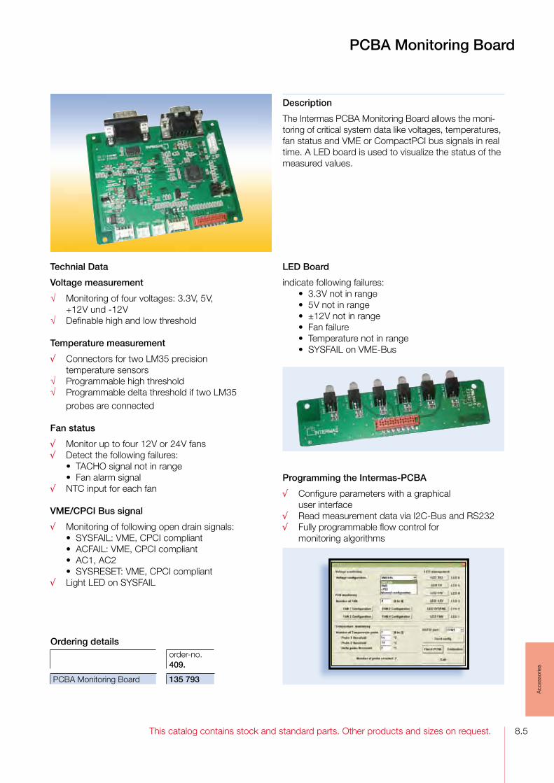
8.5This catalog contains stock and standard parts. Other products and sizes on request.
Acc
esso
ries
Description
The Intermas PCBA Monitoring Board allows the moni-toring of critical system data like voltages, temperatures, fan status and VME or CompactPCI bus signals in real time. A LED board is used to visualize the status of the measured values.
PCBA Monitoring Board
Technial Data
Voltage measurement
√ Monitoring of four voltages: 3.3 V, 5 V, +12 V und -12 V√ Definable high and low threshold
Temperature measurement
√ Connectors for two LM35 precision temperature sensors√ Programmable high threshold√ Programmable delta threshold if two LM35 probes are connected
Fan status
√ Monitor up to four 12 V or 24 V fans√ Detect the following failures: •TACHOsignalnotinrange •Fanalarmsignal√ NTC input for each fan
VME/CPCI Bus signal
√ Monitoring of following open drain signals: •SYSFAIL:VME,CPCIcompliant •ACFAIL:VME,CPCIcompliant •AC1,AC2 •SYSRESET:VME,CPCIcompliant √ LightLEDonSYSFAIL
LED Board
indicate following failures: •3.3 V not in range •5 V not in range •±12 V not in range •Fanfailure •Temperaturenotinrange •SYSFAILonVME-Bus
Programming the Intermas-PCBA
√ Configure parameters with a graphical user interface√ Read measurement data via I2C-Bus and RS232√ Fully programmable flow control for monitoring algorithms
Ordering detailsorder-no.409.
PCBA Monitoring Board 135 793

This catalog contains stock and standard parts. Other products and sizes on request.8.6
Acc
esso
ries
RFI Spring A2 and F3
RFI Spring A2Shielding between the cover plates and the subrack. The spring is snapped into the profile channel of the horizontal rail.It can be cut in 10 mm lengths.
Material: stainless steel, 0.1 mm thick
Cover plate RFI spring A2
Horizontal rail
086292
RFI Spring F3Shielding between the front panels and between front panel and flan-ge as well as shielding the cover plates of the DiVar housing.It can be cut in 7.41 mm lengths.
Material: stainless steel, 0.08 mm thick
110965
Shielding between the front panel and between front panel and flange
Flat front panels Extruded front panel
Side panel
Flange
RFI spring F3
Ordering detailsnom. width [HP]
length [mm]
order no. 409.
RFI spring A2 36 182 107 724RFI spring A2 42 217 090 800RFI spring A2 84 427 085 011
Ordering details
nom. height [U]
height [mm]
order no. 409.
RFI spring F3-2 2 51.37 112 386RFI spring F3-3-IEEE 3 95.83 111 112RFI spring F3-3 3 110.65 111 636RFI spring F3-4 4 155.11 112 387RFI spring F3-6-IEEE 6 229.21 111 116RFI spring F3-6 6 244.03 111 637

8.7This catalog contains stock and standard parts. Other products and sizes on request.
Acc
esso
ries
RFI Spring F1, Contact Profile and RFI Spring P2
RFI Spring F1Shielding between the front panel and side panel with the contact profile of the InterRail subrack.
Material: CuSn 0.1 mm thick
Contact ProfileShielding between front panel and side panel with the RFI spring F1 of the InterRail subrack.
Material: aluminumFinish: colorless chromated
RFI Spring P2Shielding front panels and rear panel to the horizontal rail. The spring is snapped into the profile channel of the horizontal rail.It can be cut in 15.24 mm lengths.
Material: stainless steel, 0.08 mm thick
Front panel/rear panel
RFI spring P2
Horizontal rail
106545
092824
Side panel
RFI spring F1
Contact profile
Ordering details
nom. height [U]
height [mm]
order no. 409.
RFI spring F1-3 3 106.9 093 400RFI spring F1-6 6 240.25 093 401
Ordering details
nom. height [U]
height [mm]
order no. 409.
Contact profile -3 3 107.5 092 923Contact profile -6 6 240.85 092 924
Ordering details
nom. width [HP]
length[mm]
order no. 409.
RFI spring P2 42 212.36 106 546RFI spring P2 84 425.72 106 547

This catalog contains stock and standard parts. Other products and sizes on request.8.8
Acc
esso
ries
RFI Spring U1 and U2
RFI Spring U1Multiple applications. Shielding subracks, housings and cabinets with 1 mm - 2.5 mm sheet thickness.The spring can be cut in 10 mm lengths.
Material: stainless steel, 0.1 mm thick
RFI Spring U2Multiple applications. Shielding subracks, housings and cabinets with 2.5 mm sheet thickness.The spring can be cut in 10 mm lengths.
Material: stainless steel, 0.08 mm thick
108116
style A style B
Cover
RFI spring U1style B
Side panel
Cover
RFI spring U1 style A
Side panel
Subrack example of use Subrack example of use System cabinet example of use
Rail profile
RFI spring U1 Cover sheet
Subrack example of use
Cover
RFI spring U2
Side panel
RFI spring U2
Side panel
Continous front panel
Subrack example of use
Ordering details
stylesheet thick-ness [mm]
length [mm]
order no. 409.
RFI spring U1-1,0-230 A 1.0 229 114 840RFI spring U1-1,5-400 A 1.5 399 101 830RFI spring U1-2,0-270 B 2.0 269 107 323RFI spring U1-2,5-270 B 2.5 269 103 792
Ordering details
sheet thick-ness [mm]
length [mm]
order no. 409.
RFI spring U2 2.5 98.79 108 107RFI spring U2 2.5 232.14 108 108RFI spring U2 2.5 632.19 109 537
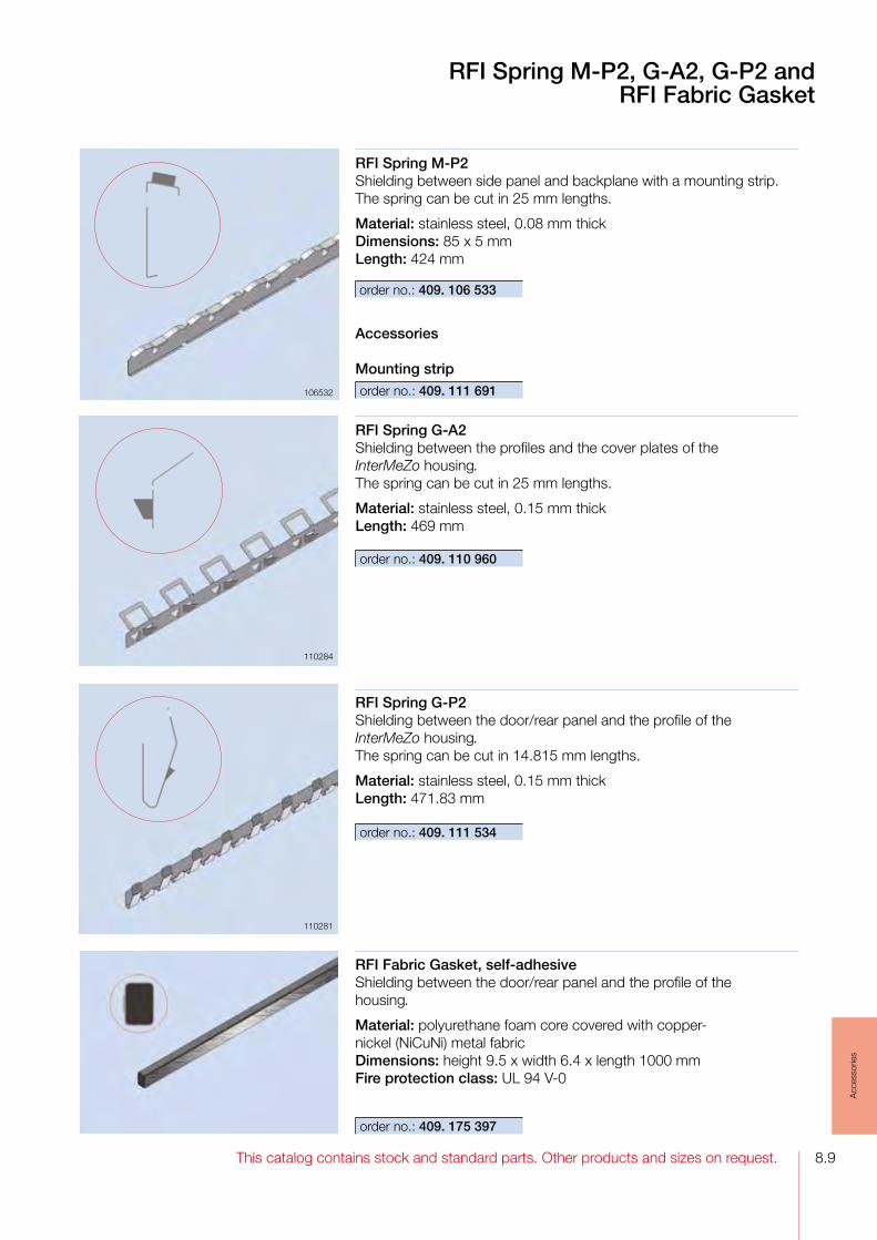
8.9This catalog contains stock and standard parts. Other products and sizes on request.
Acc
esso
ries
RFI Spring M-P2, G-A2, G-P2 andRFI Fabric Gasket
RFI Spring G-A2Shielding between the profiles and the cover plates of the InterMeZo housing.The spring can be cut in 25 mm lengths.
Material: stainless steel, 0.15 mm thickLength: 469 mm
110284
RFI Spring G-P2Shielding between the door/rear panel and the profile of the InterMeZo housing.The spring can be cut in 14.815 mm lengths.
Material: stainless steel, 0.15 mm thickLength: 471.83 mm
110281
RFI Spring M-P2Shielding between side panel and backplane with a mounting strip.The spring can be cut in 25 mm lengths.
Material: stainless steel, 0.08 mm thickDimensions: 85 x 5 mmLength: 424 mm
106532
110281
order no.: 409. 106 533
order no.: 409. 110 960
order no.: 409. 111 534
Accessories
Mounting striporder no.: 409. 111 691
RFI Fabric Gasket, self-adhesiveShielding between the door/rear panel and the profile of the housing.
Material: polyurethane foam core covered with copper-nickel (NiCuNi) metal fabricDimensions: height 9.5 x width 6.4 x length 1000 mmFire protection class: UL 94 V-0
order no.: 409. 175 397

9.2
013013 904 7.5013 910 7.5013 911 3.64, 3.68 3.69, 3.70 3.71, 3.72 3.85, 4.10 4.12013 919 3.44, 2.7013 938 3.68, 3.70 3.71, 3.72 3.85, 3.94 7.5
017017 929 3.85017 956 3.85017 956 3.89
018018 028 7.5018 055 3.65
022022 622 7.4022 672 4.11022 714 7.6022 791 3.85022 792 3.85, 4.10022 793 3.85, 4.10022 794 3.85, 4.10022 796 3.85, 4.10022 798 3.85, 4.10022 800 4.10022 802 3.85022 807 3.85, 4.10022 814 4.10
024024 361 3.64024 380 3.64024 567 7.4024 738 3.61024 740 3.61024 830 3.95
026026 068 3.39026 519 8.2026 520 8.2026 586 3.64
031031 015 7.4031 018 7.5031 019 7.5031 020 7.5031 021 7.3031 022 7.3031 023 7.5031 024 7.5031 030 7.3031 031 7.3031 120 7.5031 123 7.5031 124 7.9031 125 7.9031 583 7.6
032032 518 7.11032 519 7.12032 520 7.10, 7.12032 523 7.12032 549 7.11032 550 7.12032 551 7.10, 7.12032 552 7.12032 553 7.10032 554 7.10032 555 7.11032 556 7.11032 563 7.10032 564 7.10032 565 7.10032 566 7.10032 567 7.10032 568 7.10032 569 7.10032 574 7.11032 575 7.10, 7.12032 708 3.64, 4.12 7.5032 766 7.13032 767 7.13
033033 188 7.6033 189 7.6
034034 532 7.13034 533 7.13034 724 7.13, 7.18
035035 004 3.93035 206 7.11035 207 7.10035 316 7.12035 528 3.93035 529 3.93035 630 7.5035 665 3.93
038038 687 4.9038 689 4.9038 691 4.9038 693 4.9038 700 4.9038 707 4.9038 721 4.9038 763 4.9038 765 4.9038 767 4.9038 769 4.9038 776 4.9038 783 4.9038 797 4.9
039039 540 4.7039 542 4.7039 543 4.7039 546 4.7039 547 4.7039 603 4.7039 604 4.7039 691 3.66, 3.69 4.10, 4.12039 851 4.12039 853 4.12039 855 4.12039 857 4.12039 864 4.12039 954 4.12039 968 4.12
040040 348 4.13040 350 4.13040 352 4.13040 354 4.13040 361 4.13040 368 4.13040 382 4.13040 385 3.93
040 386 3.93040 387 3.93040 401 3.85, 4.10 4.12040 419 3.44040 420 3.44040 652 3.85040 969 4.10
041041 008 4.11041 012 4.11041 657 3.85041 660 7.4
042042 218 7.4042 219 7.4
043043 035 3.93043 036 3.93043 488 4.11043 514 4.8043 516 4.8043 518 4.8043 525 4.8043 532 4.8043 546 4.8043 586 7.3043 598 7.3043 606 7.3043 610 7.3043 622 7.3
044044 090 4.12044 214 7.6
045045 210 7.3045 235 7.3045 891 7.3045 894 7.3045 897 7.3
046046 098 4.11046 999 4.12
047047 221 3.50047 243 3.50
List of Order-Numbers409.
Order no. 409.
Order no. 409.
Order no. 409.
Order no. 409.

9.3
047 285 3.50047 421 3.49047 443 3.49047 485 3.49047 601 3.66047 621 3.52047 643 3.52047 685 3.52047 821 3.51047 843 3.51047 885 3.51
048048 684 3.54048 784 3.54
049049 668 1.10049 670 1.10049 677 1.9049 679 1.9049 680 1.9049 681 1.9049 682 1.9049 721 3.49049 743 3.49049 785 3.49049 921 3.52049 943 3.52049 985 3.52
050050 121 3.51050 129 3.51050 143 3.51050 185 3.51050 567 1.9050 688 1.8
051051 981 3.7, 3.9 3.16, 3.17 3.18, 3.19 3.24, 3.26 3.27, 3.65
052052 156 3.36, 3.37 3.39052 720 3.75
053053 321 3.46
053 329 3.46053 343 3.46053 385 3.46
056056 135 3.93
057057 680 7.20
058058 102 3.67, 3.69 3.70, 3.71 3.74, 3.94058 447 7.20058 449 7.20058 451 7.20058 910 3.85058 910 4.10058 912 3.85, 4.10058 914 4.10058 916 3.85058 921 3.85, 4.10058 928 4.10058 942 3.85, 4.10058 944 3.29
059059 270 7.20059 632 3.70059 634 3.70059 636 3.70059 640 2.9
061061 051 3.71061 052 3.71061 059 3.71061 060 3.71061 061 3.71061 062 3.71061 086 3.71061 088 3.71061 443 7.20061 468 3.67061 469 3.67061 526 3.67061 541 3.65
062062 043 3.46062 085 3.46062 093 7.20
062 094 7.20062 095 7.20
064064 687 3.59064 740 7.6064 947 3.59
065065 430 7.20065 819 3.45065 882 3.94065 883 3.94065 888 3.89
067067 624 3.55, 3.56 3.57, 3.94
068068 089 7.3068 108 7.3068 698 3.75068 760 1.10
069069 047 3.59069 302 1.10069 369 1.9069 755 7.13069 774 3.70
070070 323 7.3070 425 7.3070 476 7.5070 617 7.6070 620 7.9070 621 7.9070 969 7.4
071071 015 7.4071 876 7.9
072072 533 3.59072 619 7.11072 620 7.11
073073 659 7.9
074074 056 1.7074 057 1.7074 202 7.4074 203 7.4074 387 2.7, 3.44
077077 038 7.4077 042 7.4077 045 7.4077 048 7.4077 051 7.4077 055 7.4077 058 7.4077 111 7.5077 112 7.5077 516 7.9
078078 428 3.81078 641 1.8078 646 1.8078 693 3.36078 942 3.58
079079 184 3.54079 202 4.7079 203 4.7079 284 3.54079 384 3.54079 521 3.46079 543 3.46079 585 3.46
080080 068 3.70080 695 7.20080 696 7.20080 697 7.20080 939 7.20080 941 7.20080 943 7.20
081081 039 1.10
082082 063 3.58082 121 3.49082 143 3.49082 185 3.49
Order no. 409.
Order no. 409.
Order no. 409.
Order no. 409.
List of Order-Numbers409.
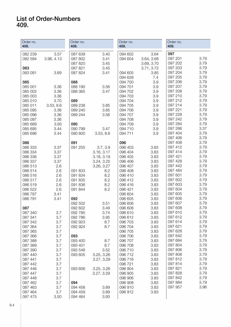
9.4
082 239 3.57082 594 3.96, 4.13
083083 091 3.69
085085 001 3.36085 002 3.36085 003 3.36085 010 3.70085 011 3.53, 8.6085 095 3.36085 096 3.36085 097 3.36085 689 3.93085 695 3.44085 696 3.44
086086 333 3.37086 334 3.37086 336 3.37086 337 3.37086 513 2.6086 514 2.6086 516 2.6086 517 2.6086 519 2.6086 522 2.6086 787 3.41086 791 3.41
087087 340 3.7087 341 3.7087 342 3.7087 364 3.7087 365 3.7087 366 3.7087 388 3.7087 389 3.7087 390 3.7087 440 3.7087 441 3.7087 442 3.7087 446 3.7087 447 3.7087 448 3.7087 462 3.7087 463 3.7087 464 3.7087 475 3.50
087 639 3.40087 802 3.41087 820 3.45087 821 3.45087 824 3.41
088088 190 3.56088 365 3.47
089089 238 3.85089 240 3.85089 244 3.56
090090 799 3.47090 800 3.53, 8.6
091091 255 3.7, 3.9 3.16, 3.17 3.18, 3.19 3.24, 3.25 3.26, 3.27091 833 8.2091 834 8.2091 835 8.2091 836 8.2091 844 8.2
092092 502 3.51092 602 3.49092 785 3.74092 786 3.95092 923 8.7092 924 8.7
093093 400 8.7093 401 8.7093 548 3.52093 605 3.25, 3.26 3.27, 3.29
093 606 3.25, 3.26 3.27, 3.29
094094 458 3.89094 459 3.89094 464 3.93
094 602 3.64094 604 3.64, 3.68 3.69, 3.70 3.71, 3.72094 605 3.85094 628 7.4094 700 3.9094 701 3.9094 702 3.9094 703 3.9094 704 3.9094 705 3.9094 706 3.9094 707 3.9094 708 3.9094 709 3.9094 710 3.9094 711 3.9
096096 403 3.83096 404 3.83096 405 3.83096 406 3.83096 407 3.83096 408 3.83096 410 3.83096 412 3.83096 416 3.83096 421 3.83096 604 3.83096 605 3.83096 606 3.83096 608 3.83096 610 3.83096 612 3.83096 703 3.83096 704 3.83096 705 3.83096 706 3.83096 707 3.83096 708 3.83096 710 3.83096 712 3.83096 716 3.83096 721 3.83096 904 3.83096 905 3.83096 906 3.83096 908 3.83096 910 3.83096 912 3.83
097097 201 3.79097 202 3.79097 203 3.79097 204 3.79097 205 3.79097 206 3.79097 207 3.79097 208 3.79097 210 3.79097 212 3.79097 214 3.79097 221 3.79097 228 3.79097 242 3.79097 284 3.79097 286 3.37097 404 3.79097 406 3.79097 408 3.79097 412 3.79097 414 3.79097 421 3.79097 428 3.79097 442 3.79097 484 3.79097 601 3.79097 602 3.79097 603 3.79097 604 3.79097 605 3.79097 606 3.79097 607 3.79097 608 3.79097 610 3.79097 612 3.79097 614 3.79097 621 3.79097 628 3.79097 642 3.79097 684 3.79097 804 3.79097 806 3.79097 808 3.79097 812 3.79097 814 3.79097 821 3.79097 828 3.79097 842 3.79097 884 3.79097 957 3.96
List of Order-Numbers409.
Order no. 409.
Order no. 409.
Order no. 409.
Order no. 409.

9.5
098098 986 7.4098 989 7.4098 991 7.4
099099 730 3.94099 731 3.94099 883 3.54
100100 538 3.79, 3.96 4.13100 539 3.79, 3.96 4.13100 540 3.96, 4.13100 650 7.7100 652 7.7100 660 7.7100 662 7.7100 667 3.85100 843 3.62
101101 276 3.70101 385 7.4101 830 8.8101 843 3.89101 844 3.89101 917 3.96, 4.13101 918 3.96, 4.13101 923 3.89101 276 3.70101 385 7.4101 830 8.8101 843 3.89101 844 3.89101 917 3.58, 3.79 3.96, 4.10 4.13101 918 3.96, 4.13101 923 3.89101 924 3.89
102102 109 7.7102 110 7.7102 112 7.7102 113 7.7102 114 3.85102 115 3.85102 117 3.89
102 118 3.89102 297 3.75102 344 3.87102 348 3.87102 352 3.87102 356 3.87102 361 3.87102 384 3.87102 388 3.87102 392 3.87102 404 3.87102 405 3.87102 406 3.87102 408 3.87102 410 3.87102 412 3.87102 416 3.87102 421 3.87102 432 3.29102 454 3.87102 458 3.87102 462 3.87102 822 3.28
103103 005 3.85103 006 3.85, 4.10103 007 3.85, 4.10103 008 3.85, 4.10103 205 3.85103 206 3.85, 4.10103 207 3.85, 4.10103 208 3.85, 4.10103 358 3.68, 3.69 3.70, 3.72 3.74103 777 3.62103 792 8.8103 810 3.85, 4.10103 812 3.85, 4.10103 814 4.10103 816 3.85103 821 3.85, 4.10103 828 4.10103 842 3.85, 4.10
104104 030 3.50104 994 3.49
105105 380 7.3105 602 3.40
105 655 3.53105 656 3.53105 789 3.44105 790 3.54
106106 102 3.49106 103 3.49106 530 3.74106 531 3.74106 533 8.9106 546 3.53, 8.7106 547 3.16, 3.17 3.18, 3.19 3.25, 3.26 3.27, 3.29 3.53, 8.7106 750 3.37106 751 3.62
107107 323 8.8107 342 3.58107 518 3.83107 520 3.83107 521 3.83107 522 3.83107 716 3.28107 719 3.40107 721 3.50107 722 3.53107 723 3.56107 724 8.6107 727 3.94107 728 3.94107 841 3.50107 842 3.50107 846 3.53107 847 3.53107 905 3.56107 906 3.56
108108 008 3.52108 012 3.60108 045 3.60108 061 3.50108 101 3.70108 107 8.8108 108 8.8108 120 3.70108 157 3.70108 173 3.66
108 246 3.50108 250 3.28108 251 3.28108 252 3.29108 253 3.29108 254 3.29108 255 3.29108 274 3.25108 275 3.25108 875 3.57108 876 3.57108 962 4.10108 963 4.10, 4.13108 987 3.51108 988 3.51
109109 058 3.70109 537 8.8109 934 3.47109 937 3.50109 984 2.6109 985 2.6109 986 2.6109 987 2.6109 988 2.6
110110 201 3.36110 202 3.36110 234 3.36110 238 3.36110 248 3.36110 249 3.36110 360 2.7110 361 2.7110 366 2.7110 367 2.7110 368 2.7110 370 2.7110 372 2.7110 375 2.7110 376 2.7110 378 2.7110 379 2.7110 381 2.7110 382 2.7110 392 2.6110 395 2.6110 452 2.6110 453 2.6110 454 2.6110 455 2.6
List of Order-Numbers409.
Order no. 409.
Order no. 409.
Order no. 409.
Order no. 409.

9.6
110 456 2.6110 457 2.6110 960 8.9
111111 112 3.58, 3.81 3.84, 3.88 3.91, 3.92 4.11, 4.14 8.6111 116 3.58, 3.81 3.84, 3.88 3.91, 3.92 4.11, 8.6111 157 3.68111 182 3.47111 184 3.55111 199 3.52111 245 7.15111 285 2.6111 286 2.6111 287 2.6111 534 8.9111 556 2.6111 557 2.6111 559 2.6111 560 2.6111 561 2.6111 562 2.6111 604 3.88111 605 3.88111 606 3.88111 608 3.80111 609 3.80111 610 3.80111 611 3.80111 613 3.88111 614 3.88111 615 3.88111 616 3.88111 618 3.80111 619 3.80111 620 3.80111 621 3.80111 636 3.42, 3.44 8.6111 637 3.42, 3.44 8.6111 691 8.9111 774 2.9111 775 7.15111 847 3.88
112112 054 3.64112 055 3.64112 092 2.7112 093 2.7112 094 2.7112 152 3.91112 154 3.91112 202 3.42112 205 3.42112 234 3.42112 252 3.80112 258 3.80112 279 7.18112 386 3.42, 8.6112 387 3.42, 8.6112 400 3.91112 401 3.91112 402 3.91112 403 3.91112 404 3.91112 405 3.91112 408 3.91112 409 3.91112 410 3.91112 411 3.91112 412 3.91112 413 3.91112 453 3.68112 454 3.68112 507 2.7112 551 3.80112 557 3.80112 578 3.80112 581 3.80112 611 3.80112 617 3.80112 638 3.80112 641 3.80112 644 3.88112 650 3.88112 668 3.88112 725 3.88112 773 3.91112 778 3.91112 790 3.91112 821 3.80112 872 3.39112 876 3.39112 943 3.80
113113 027 3.80
113 028 3.80113 029 3.80113 030 3.80113 079 3.91113 147 3.88113 148 3.88113 149 3.88113 170 3.88113 171 3.88113 172 3.88113 400 3.72113 450 3.72, 3.73113 583 3.80113 586 3.80113 589 3.80113 590 3.80113 592 3.80113 593 3.80113 594 3.80113 595 3.80113 596 3.80113 598 3.80113 599 3.80113 608 3.80113 609 3.80113 611 3.80113 612 3.80113 613 3.80113 614 3.80113 617 3.80113 620 3.88113 622 3.88113 626 3.88113 640 3.88113 641 3.91113 647 3.91113 654 3.91113 655 3.88113 656 3.88113 657 3.88113 658 3.88113 659 3.88113 660 3.88113 661 3.88113 662 3.88113 663 3.88113 665 3.88113 667 3.88113 668 3.88113 669 3.88113 670 3.88113 671 3.91113 672 3.91
113 673 3.91113 674 3.91113 675 3.91113 676 3.91113 685 3.84113 693 3.84113 705 3.81113 706 3.81113 711 3.84113 713 3.72, 3.73113 723 3.84113 725 3.84113 729 3.84113 762 3.84113 788 7.18113 824 7.15113 826 7.17113 828 7.17113 830 7.17113 838 7.15113 840 7.15113 841 7.15113 849 7.15113 860 7.15113 905 3.73113 948 3.81113 950 3.81
114114 007 7.17114 082 3.80114 119 7.16114 120 7.16114 121 7.16114 122 7.16114 240 3.39114 241 3.39114 242 3.39114 243 3.39114 361 3.80114 362 3.80114 363 3.80114 365 3.80114 366 3.80114 367 3.80114 368 3.80114 370 3.84114 371 3.84114 372 3.84114 373 3.84114 374 3.84114 376 3.84114 377 3.84
List of Order-Numbers409.
Order no. 409.
Order no. 409.
Order no. 409.
Order no. 409.

9.7
114 378 3.84114 379 3.84114 380 3.84114 381 3.84114 383 3.84114 384 3.80114 385 3.80114 386 3.80114 387 3.80114 388 3.80114 389 3.80114 390 3.80114 391 3.80114 392 3.80114 393 3.80114 396 3.84114 397 3.84114 399 3.84114 400 3.84114 401 3.84114 403 3.84114 404 3.84114 405 3.84114 406 3.84114 407 3.84114 408 3.84114 410 3.84114 413 3.91114 415 3.91114 453 3.80114 454 3.80114 455 3.80114 458 3.80114 459 3.80114 463 3.91114 464 3.80114 465 3.80114 466 3.80114 469 3.80114 470 3.80114 475 3.91114 476 3.80114 487 3.80114 537 3.84114 538 3.84114 540 3.84114 541 3.84114 562 3.47, 3.81114 612 3.42114 618 3.42114 708 3.43, 3.81114 715 3.43, 3.81114 758 3.39
114 759 3.39114 760 3.39114 762 3.39114 766 3.39114 840 8.8114 933 7.17114 982 7.19114 983 7.19114 985 7.19
115115 005 4.9115 007 4.9115 009 4.9115 011 4.9115 018 4.9115 025 4.9115 039 4.9115 042 3.51115 095 7.19115 171 3.70115 224 3.55115 236 3.70115 270 3.55115 540 3.55115 542 3.55115 701 3.52115 771 3.48115 823 3.48115 824 3.48115 898 3.57115 899 3.57
116116 200 3.69116 319 3.58116 333 3.60116 334 3.60116 335 3.60116 336 3.60116 416 3.60116 418 3.60116 440 3.72116 441 3.73116 442 3.72, 3.73116 484 3.19116 507 3.48116 586 3.49116 588 3.48116 603 3.55
117117 108 7.19
118118 374 3.44118 433 3.80, 3.84 3.88, 3.91 3.92, 4.11 4.14118 608 3.62
119119 013 4.12119 024 4.9119 026 4.9119 028 4.9119 030 4.9119 037 4.9119 044 4.9119 058 4.9
120120 282 4.9120 283 4.9120 790 3.61
121121 329 3.55121 519 3.51121 808 2.9121 941 3.61
122122 131 3.44122 295 3.32122 297 3.32122 300 3.33122 301 3.33122 356 2.10122 357 2.10122 358 2.10122 359 2.10122 360 2.10122 377 3.52122 378 3.52122 379 3.53122 380 4.9122 421 3.48122 549 3.55122 550 3.55122 607 3.92122 608 3.92122 609 3.92122 610 3.92122 611 3.92122 612 3.92
122 622 3.83122 624 3.83122 625 3.83122 626 3.83122 627 3.83122 628 3.83122 639 3.87122 640 3.87122 641 3.87122 642 3.87122 643 3.87122 644 3.87122 645 3.87122 646 3.87122 647 3.87122 648 3.60122 649 3.60122 650 3.60122 651 3.60
130130 883 3.62130 889 3.72130 890 3.62
131131 354 1.8131 478 3.62131 548 3.62131 550 1.9131 652 2.7131 688 3.62131 701 3.62131 813 3.62131 836 3.62131 845 3.62131 973 3.72
132132 038 3.62132 240 1.9132 464 1.10132 601 1.9132 603 1.9132 604 1.9132 605 1.9132 606 1.9132 735 1.10132 778 1.8
List of Order-Numbers409.
Order no. 409.
Order no. 409.
Order no. 409.
Order no. 409.

9.8
133133 305 2.9133 306 2.9133 307 2.9133 308 2.9
135135 793 8.5
136136 207 8.4136 208 8.4136 209 8.4136 210 8.4136 211 8.4136 413 8.4
161161 034 3.19161 059 3.51161 104 3.55161 105 3.55161 110 3.43161 113 3.43161 155 3.39161 156 3.39161 157 3.39161 160 3.39161 161 3.59161 162 3.59161 165 3.59161 166 3.59161 173 3.39161 174 3.39161 188 3.39161 189 3.39161 193 3.39161 245 3.49
162162 610 3.24162 611 3.24162 612 3.24162 613 3.24162 614 3.24162 700 3.7162 701 3.7162 703 3.7162 704 3.7, 3.9162 705 3.7, 3.9162 708 3.16162 709 3.16162 710 3.16
162 711 3.16162 712 3.16162 713 3.16162 714 3.16162 715 3.16162 716 3.17162 717 3.17162 718 3.17162 719 3.17162 720 3.18162 721 3.18162 722 3.18162 723 3.18162 724 3.18162 725 3.18162 726 3.18162 727 3.18162 728 3.19162 729 3.19162 730 3.25162 731 3.25162 732 3.25162 733 3.25162 734 3.26162 735 3.26162 736 3.26162 737 3.26162 738 3.26162 739 3.26162 740 3.27162 741 3.27162 742 3.27162 743 3.27162 744 3.27162 745 3.27
165165 602 4.4165 603 4.4165 604 4.4165 605 4.4165 606 4.4165 607 4.4165 610 4.4165 611 4.4165 612 4.4165 613 4.4165 614 4.4165 615 4.4165 617 4.4165 625 4.4165 634 4.4165 635 4.4
165 636 4.4165 637 4.4165 638 4.4165 639 4.4165 642 4.4165 643 4.4165 644 4.4165 645 4.4165 646 4.4165 647 4.4165 698 4.5165 699 4.5165 700 4.5165 701 4.5165 702 4.5165 703 4.5165 706 4.5165 707 4.5165 708 4.5165 709 4.5165 710 4.5165 711 4.5165 713 4.5165 721 4.5165 730 4.5165 731 4.5165 732 4.5165 733 4.5165 734 4.5165 735 4.5165 738 4.5165 739 4.5165 740 4.5165 741 4.5165 742 4.5165 743 4.5165 842 4.5165 843 4.5165 844 4.5165 845 4.5165 846 4.5165 847 4.5165 850 4.5165 851 4.5165 852 4.5165 853 4.5165 854 4.5165 855 4.5165 858 4.5165 859 4.5165 860 4.5165 861 4.5165 862 4.5
List of Order-Numbers409.
165 863 4.5165 866 4.5165 867 4.5165 868 4.5165 869 4.5165 870 4.5165 871 4.5165 873 4.5165 881 4.5165 896 4.6165 897 4.6165 898 4.6
166166 100 4.6166 101 4.6166 102 4.6166 112 4.6166 113 4.6166 114 4.6166 116 4.6166 117 4.6166 118 4.6166 208 2.5166 209 2.5166 210 2.5166 211 2.5166 212 2.5166 213 2.5166 214 2.5166 215 2.5166 216 2.5166 217 2.5166 218 2.5166 219 2.5166 220 2.5166 237 4.8166 238 4.8166 239 4.8166 240 4.8166 241 4.8166 242 4.8166 243 4.8166 261 1.6166 262 1.6166 263 1.6166 264 1.6166 265 1.6166 266 1.6166 270 3.59166 274 8.3166 276 8.3166 286 7.15
Order no. 409.
Order no. 409.
Order no. 409.
Order no. 409.

9.9
List of Order-Numbers409. and Additional
017-010064F 6.2 6.4, 6.6 6.8, 6.10 6.12, 6.13 6.14017-010115K 6.2 6.4, 6.6 6.8, 6.10 6.12, 6.13 6.14
116-010016D 6.2116-010018J 6.6116-010022A 6.4116-010046C 6.6116-010063D 6.2116-010064A 6.2116-010066F 6.2116-010070J 6.2116-010072C 6.2116-010078G 6.6116-010101G 6.6116-010175L 6.14116-010186D 6.13116-010194F 6.12116-020018B 6.10116-020026D 6.10116-031530B 6.10116-040151K 6.8116-040152G 6.8116-040153D 6.8116-040301J 6.8116-040302F 6.8116-040303C 6.8116-040311E 6.8116-040312B 6.8116-040313K 6.8
148-010000K 6.6148-011001G 6.12 6.13148-010011J 6.4148-011002D 6.2148-010019G 6.2148-010020H 6.6 6.14148-010021E 6.2
Order no. 409.
AdditionalOrder no.
166 287 7.15166 288 7.15
167167 416 1.8
168168 900 3.87168 901 3.87168 902 3.87168 903 3.87168 904 3.87168 905 3.87168 906 3.87168 907 3.87168 908 3.87168 909 3.87168 910 3.87168 911 3.87168 912 3.87168 913 3.87168 914 3.87168 915 3.87168 916 3.87168 917 3.87168 918 3.87168 919 3.87168 920 3.87168 921 3.87168 935 2.12168 936 2.12168 937 2.12168 938 4.14168 939 4.14168 940 4.14168 941 4.14
172172 548 2.8172 610 2.8172 620 2.8172 621 2.8172 630 2.8172 631 2.8172 640 2.8172 641 2.8172 650 2.8172 651 2.8172 660 2.8172 661 2.8
175175 397 8.9

9.10
Glossary
100
100 A Insulated Bus Bar 7.20
19”
19” Cross-Flow Fan 8.219” Casing Door for InterMeZo Housing 2.619” Front Panel 2.619” Unit Support 1.819” Fan Unit 1 U 8.319” Modular Assembly System 0.619”-2 U Rackmount Industrial PC 5.519”-4 U Rackmount Industrial PC 5.4
A
AC/DC Converter 6.2Accessories 8.1Accessories for Cabinets 1.8Accessories for Card Guides 3.73Accessories for Cassettes 4.11Accessories for Connectors 7.6 Accessories for InterLock Desktop Housing 2.9Accessories for Metal Interface Housings RFI 20 COD 7.19Accessories for Matal Interface Housings RFI E/F 7.18Accessories for Plastic Interface Housings 7.13Accessories for Subracks 3.35Accessories for System Cabinet InterRack 1.8Accessories for InterMeZo Housing 2.6Accessories for UFanRail 8.4Air flow guide 8.4Angle for Cassette 4.12
B
Blind Front Panels 3.78Blind Front Panels RFI 3.80Bus Bar, Insulated 7.20Box Industrial PC 5.3
C
Cabinets Accessories 1.8Cabinet InterRack 1.1Cable Clamp Kit for Interface Housings 7.18Cable Sleeve for Interface Housings 7.13Cage Nut 2.7Card Guide CONN 3.69Card Guide ECONOMY 3.66Card Guide for Cassette 4.11Card Guide IEEE 3.72Card Guide UNIVERSAL 3.67Card Guide VARIO 3.71Card Guide VIB 3.70Card Guide with integrated push and pull assist 3.68Carrying Handle for InterMeZo Housing 2.7Carrying Handle for InterCase Housing 2.8Casing Door, 19” -, for InterMeZo Housing 2.6Cassettes 4.1Cassette Angle 4.12Cassettes, Accessories 4.11Cassette with Cover Hood 4.6Cassette with four Depth Profiles 4.5Cassette with Extruded Side Walls 4.4Cassette with Heat Sink 4.14
Cassette, Individual Parts 4.7Castors for InterMeZo Housing 2.7Center Profile, Horizontal Rails 3.51Closing Profile F und RFI-F3 3.44Coding Key for IEC 60 603 7.2Coding Kit for Metal Interface Housings 7.18Coding Pin RFI 7.19Coding Strips for Connectors 7.6Coding Strip RFI for Metal Interface Housing 7.19CompactPCI-System-Modules 3.30Configuration InterMeZo Housing 2.4Configuration System Cabinet InterRack 1.4Configuration System-Modules CPCI 3.34CONN, Card Guide 3.69Connector, Accessories 7.6Connectors Coding Key 7.2Connectors Styles B, C, D and E 7.3Corner Connector for Cabinet InterRack 1.8Cover for Euroboards 7.7Cover for Ventilation Openings 3.74Cover Hood and Cassettes 4.6Cover Plates 3.54 - inside, - outside 3.55 - F, screw on, - Fi, slide in, - Fs, slide in 3.54 - InterRail 3.56Rear I/O-Subrack RFI-SHIELDED 3.19Crimp-Snap-In-Contacts 7.5Crimp-Pliers for Connectors 7.5Cross-Flow Fan, 19” 8.2Custom Logo Strip for Cabinet InterRack 1.10Customer specific electronic systems 5.6
D
DC/DC-coverter 6.14Depth Profiles for Cassettes 4.5 Depth Profiles Individual for Cassettes 4.7Desktop Housing, InterCase 2.8Desktop Housing, Interlock 2.9DiVar Housing 2.10DIN Standards and IEC Publications 0.6DIN EN ISO 9001:2000 0.10Document Box for System Cabinet InterRack 1.10Door for InterMeZo Housing 2.6Door Hinge 180° 1.9
E
Ejector Handle for front panels 3.87Ejector Handle 4 HP 3.89Euroboards, Cover for 7.7ECONOMY, Card Guide 3.66Extruded Side Walls for Cassettes 4.4
F
Fabric Gasket 8.9Fan 19” Cross-Flow 8.2Fan Unit 1 U,19” 8.3Fanless Box Industrial PC 5.3Female Connectors 7.3Flange F 3.41Flange for Wall Mounting 3.43Flange FP 3.43Flange RFI 3.42Flange without Nose 3.41

9.11
Glossary
FLEXIBLE Subrack 3.4FLEXIBLE Subrack Fi 3.6 - Fs 3.8Foot kit 2.9Front Connector 3.94 - FEE 3.95 - plastic 3.94 - Support 3.95Front Panels, Blind 3.78Front Panels, Blind for RFI 3.80Front Panel for Cassette 4.9Front Panel Support 3.95Front Panel, 19” - 2.6Front Panel, Plastic 3.93Front Panels, General 3.76Front Panels hinged 3.81Front Panels plug-in 3.81Front Panels RFI with Ejector Handle 3.88Front Panels RFI with IEEE Handle 3.90Front Panels RFI with IEEE Handle gray 3.91Front Panels with Ejector Handle 3.86Front Panels with Handle 3.82Front Profile VE1, 2xVE1, VE12 3.46Front Profile V12-RFI, V12-SFP-RFI, V12-IEEE 3.47Front Profile V1-HUCK, V1-HUCK-IEEE 3.48
G
Grounding Bushing M 2,5 3.96Grounding Contact for Front Panels 3.74Guide Components, Metal 7.17Guide Components, metallized 7.16Guide Components, Plastic 7.10Gusset Plate for System Cabinet InterRack 1.8
H
Handle for Subracks 3.44Handle 4 HP, Ejector 3.89Handle FP 3.85Handle, Snap-in 3.93Heat Sink for Cassettes 4.14Hinged Front Panel 85 HP 3.81Horizontal Mounting Frame 3.59Horizontal Rails 3.46Housing InterMeZo 2.2Housing InterMeZo, Configuration 2.4Housing, DiVar 2.9Housing, InterCase Desktop- 2.8Housing InterLock 2.12Housings 2.1
I
Ident Plate 4HP 3.89ICE Publications 0.6IEEE Card Guide 3.72IEEE Coding Head 3.73IEEE Contact Spring 3.73IEEE-Subrack InterRail RFI 3.27IEEE-Subrack RFI-SHIELDED 3.18Implementation of the Shielding 3.14Individual Parts of the Cassette 4.7Industrial PCs 5.1Industrial PC Wallmount 5.2Industrial PC Box 5.3
Industrial PC 19” 4 U Rackmount 5.4Industrial PC 19” 2 U Rackmount 5.5Industrial PCs customer specific 5.6Insulated Bus Bar, 100A 7.20Insulating Bushing 3.65Insulating Parts 3.65Insulating Strip 3.65InterCase Desktop Housing 2.8Interface Housings, Accessories 7.13Interface Housings, Metal 7.14Interface Housings, Plastic 7.8InterLock, Housing 2.12Intermas Subracks 3.1InterMeZo Housing 2.2InterMeZo Housing, Accessories 2.6InterMeZo Housing, Configuration 2.4InterRack, Versions 1.5InterRack, System Cabinet 1.1InterRail, Cover Plate 3.56IP-Protection Classes 0.9
L
Label Strip for Subracks 3.61Labelling Rail 84 HP for Subracks 3.61LED-Board 8.5Lifting Eye Kit for System Cabinet InterRack 1.10Locking Rail 84 HP for Subracks 3.61Logo Strip, Custom for Cabinet InterRack 1.10
M
Male Connector Assembly Kit for Cassette 4.11Marking Strip for Connectors 7.6Measurement configuration, Tests and results 3.12Metal Guide Components 7.17Metal Interface Housings 7.14Metal Interface Housings RFI 7.15Metal Interface Housings, Accessories for 7.18Metallized Guide Components 7.16Modular Assembly System, 19” - 0.1Modular Structure of 19” 0.7Mounting Block for Cassette 4.12Mounting frame, horizontal 3.59Mounting kits for Housings, Screws and Nuts 2.7Mounting Rail B 3.64Mounting strip 8.9Multifunctional Profile, DiVar 2.9
P
PCBA Monitoring Board 8.5PCB Lead-In for Card Guides 3.74PCB Locking, Plastic Spring and Device Kit 3.75PCB Retainer for Cassette 4.11PCB Track Contact PROFIL 3.74Partition Wall for Subracks 3.60Plate top/bottom for Cassettes 4.9Plastic Front Connector 3.94Plastic Front Panel 3.93Plastic Guide Components 7.10Plastic Interface Housings, Accessories for 7.13Plastic Interface Housings 7.8Plug-in Front Panel 85 HP 3.81Protection Classes, IP- 0.9Protection requirements 0.8

9.12
Glossary
Power Supplies 6.1 - AC/DC converters 6.2 - DC/DC converter 6.14 - PK-Serie MONOVOLT 6.2 - PK-Serie BIVOLT 6.4 - PK-Serie TRIVOLT 6.6 - VP-Serie, 40 and 50 6.8 - VP-Serie, 80 and 150 6.10 - EC-Serie MONOVOLT 6.12 - EC-Serie TRIVOLT 6.13 - GK-Serie TRIVOLT 6.14
Q
Quick Lock E 3.96
R
Rack Versions 1.5Rackmount Industrial PC, 19” 4 U and 2 U 5.4, 5.5Rail Profile V and W for System Cabinet InterRack 1.7Rear Cover for FLEXIBLE Subracks 3.56Rear Panel 2.6Rear Panel for Cassette 4.8Retaining Parts Kit 7.19RFI Blind Front Panels 3.80RFI closing Profile F3 3.44RFI Fabric Gasket 8.9RFI Shielded IEEE for Subracks 3.18RFI Side Panel 3.38RFI Spring F3 4.11RFI Spring A2, RFI Spring F3 8.6RFI Spring F1, RFI Spring P2 8.7RFI Spring U1, RFI Spring U2 8.8RFI Spring G-A2, RFI Spring G-P2, RFI Spring M-P2 8.9Rear Profiles for Subracks - HE1, HE2 3.49 - HZE, 3.50 - H22-RFI for screw on rear cover, H22-S-RFI 3.50 - 2xHK, H12-S 3.51
S
Screw Locking M6 2.7Screw Retainer M 2,5 3.96Screw Retrainer M6 3.44Separating Wall 3.60Shell for Cassette 4.13Side Panel Connector 3.45Side Panel Extender 3.45Side Panel Fi 3.36Side Panel Fs 3.37Side Panel InterRail SNCF 3.40Side Panel RFI without Flange 3.38Single Parts of System Cabinet InterRack 1.7Slide Bar for InterMeZo Housing 2.6Snap-in Handle 3.93SNCF - Subrack InterRail 3.28SNCF NF standards in Tests 3.22Springs RFI A2, A3 8.6Springs RFI F1, P2 8.7Springs RFI U1, U2 8.8Springs RFI M-P2, G-A2 and G-P2 8.9Standard Adaptor Kit for System Cabinet InterRack 1.10Subrack Accessories 3.35Subrack Divider 3.58Subrack FLEXIBLE 3.4
Subrack FLEXIBLE Fi 3.6Subrack FLEXIBLE Fs 3.8Subrack Intermas 3.1Subrack InterRail 3.20Subrack InterRail - SNCF 3.28Subrack InterRail - SNCF RFI 3.29Subrack InterRail RFI 3.25Subrack InterRail RFI with Rear Cover 3.26Subrack InterRail RFI with Front Panel in the rear 3.26Subrack InterRail RFI-IEEE 3.27Subrack InterRail 3.23Subrack RFI-SHIELDED 3.10Subrack RFI-SHIELDED Rear I/O 3.19Subrack RFI-SHIELDED IEEE 3.18Subrack RFI-SHIELDED with Rear Cover 3.17System Cabinet InterRack 1.1System Cabinet InterRack Configuration 1.4 - Corner Connector 1.8 - Custom Logo Strip 1.10 - Door Hinge 180° 1.9 - Gusset Plate A and B 1.8 - Rail Profiles V and W 1.7 - Universal Angle 1.9 - U-Strut 1.9Systematics of the Intermas Subracks 3.2System-Module CompactPCI - 3 U - Rear I/O 3.32System-Module CompactPCI - 4 U - Rear I/O 3.33System-Module CompactPCI - 6 U - Rear I/O 3.32System-Module CompactPCI -6 U+1 U-Rear I/O 3.33System-Modules CompactPCI 3.30System-Modules CPCI, Configuration 3.34
T
Tests RFI-Shilded 3.12Tests Subrack InterRail 3.22 Threaded Strips 3.62Top/Bottom Plate for Cassette 4.9Temperature sensor 8.4
U
UFanRail 8.4Unit Support for InterMeZo Housing 2.7Unit Support, 19” - 1.8Unit-Support 1.8Universal Angle for System Cabinet InterRack 1.9UNIVERSAL Card Guide 3.67U-Strut for System Cabinet InterRack 1.9
V
VARIO Card Guide 3.71VIB Card Guide 3.70
W
Wall and Door Installation Profiles 3.60Wiring and Accessories 7.1Wallmount Industrial PC 5.2
Z
Z-Rail A 3.64

Intermas-Elcom GmbH
Intermas-Elcom GmbHDaimlerweg 6D-64293 Darmstadt
Phone: +49 (0) 61 51-13 73-0Fax: +49 (0) 61 51-13 73-100E-Mail: [email protected]: www.intermas-el.com
Intermas Schweiz GmbHFirststrasse 15 • Postfach 40CH-8835 Feusisberg SZ
Phone: +41 (0) 44-787 05 35Fax: +41 (0) 44-787 05 37E-Mail: [email protected]: www.intermas.ch
Intermas Austria GmbHRoggegasse 13A-1210 Wien
Phone: +43 (0) -1-2 94 65 99-0Fax: +43 (0) -1-2 94 65 99-20E-Mail: [email protected]: www.intermas.at
Intermas US, LLC5174 McGinnis Ferry Road 117Alpharetta, GA 30005USA
Toll Free: 1 800-811 02 36Phone: +1 770-777 20 78Fax: +1 770-777 20 80E-Mail: [email protected]: www.intermas-us.com
Intermas France SASRue de l’Industrie • BP 60687 F-60006 Beauvais Cedex
Telefon: +33 (0) 3 44 02 81 81Telefax: +33 (0) 3 44 02 57 24 E-Mail: [email protected]: www.intermas-el.fr
Intermas Canada Inc.10 Campbell DriveUxbridge, Ontario L9P 1R5Kanada
Phone: +1 416-884 76 59Fax: +1 416-884 04 76E-Mail: [email protected]: www.intermas-el.com
409.
1662
82 /
0712
· S
ubje
ct t
0 c
hang
e ·
Prin
ted
in G
erm
any