Embed Size (px)
Citation preview
1
zenon driver manual MODRTU32
v.7.00

© 2012 Ing. Punzenberger COPA-DATA GmbH
All rights reserved.
Distribution and/or reproduction of this document or parts thereof in any form are permitted solely
with the written permission of the company COPA-DATA. The technical data contained herein has been
provided solely for informational purposes and is not legally binding. Subject to change, technical or
otherwise.

3
Contents
1. Welcome to COPA-DATA help ...................................................................................................... 5
2. MODRTU32 ................................................................................................................................. 5
3. MODRTU32 - Data sheet .............................................................................................................. 6
4. Driver history .............................................................................................................................. 7
5. Requirements .............................................................................................................................. 8
5.1 PC ................................................................................................................................................................ 8
6. Configuration .............................................................................................................................. 8
6.1 Creating a driver .......................................................................................................................................... 8
6.2 Settings in the driver dialog ...................................................................................................................... 10
6.2.1 General ....................................................................................................................................... 10
6.2.2 Com ............................................................................................................................................ 13
6.2.3 Settings ....................................................................................................................................... 15
6.2.4 Connection TCP/IP ...................................................................................................................... 19
7. Creating variables ...................................................................................................................... 21
7.1 Creating variables in the Editor ................................................................................................................. 21
7.2 Addressing ................................................................................................................................................. 24
7.3 Driver objects and datatypes .................................................................................................................... 26
7.3.1 Driver objects ............................................................................................................................. 26
7.3.2 Mapping of the data types ......................................................................................................... 29
7.4 Creating variables by importing ................................................................................................................ 30
7.4.1 XML import of variables from another zenon project ................................................................ 30
7.4.2 DBF Import/Export ..................................................................................................................... 31
7.5 Driver variables ......................................................................................................................................... 37
8. Driver-specific functions ............................................................................................................ 42
9. Driver commands ...................................................................................................................... 43
10. Error analysis ............................................................................................................................. 45

4
10.1 Analysis tool .............................................................................................................................................. 45
10.2 Error numbers ........................................................................................................................................... 47
10.3 Check list ................................................................................................................................................... 48

Welcome to COPA-DATA help
5
1. Welcome to COPA-DATA help
GENERAL HELP
If you miss any information in this help chapter or have any suggestions for additions, please feel free to
contact us via e-mail: [email protected] (mailto:[email protected]).
PROJECT SUPPORT
If you have concrete questions relating to your project, please feel free to contact the support team via
e-mail: [email protected] (mailto:[email protected])
LICENSES AND MODULES
If you realize that you need additional licenses or modules, please feel free to contact the sales team via
e-mail: [email protected] (mailto:[email protected])
2. MODRTU32
The driver understands the "Modbus ASCII" protocol for serial connections, the "Modbus RTU" protocol
for serial and TCP/IP connections and the "Open Modbus TCP" protocol for TCP/IP connections. The
driver is a Modbus Master. (Process Gateway is available for Modbus slave).

MODRTU32 - Data sheet
6
3. MODRTU32 - Data sheet
General:
Driver file name MODRTU32.exe
Driver description Modbus RTU and Open Modbus TCP
PLC types All PLCs supporting Modbus RTU, Open Modbus TCP/IP or Modbus
ASCII(seriell)
PLC manufacturer ABB; Gantner; GE Fanuc; Modbus RTU; Mondial; Schiele;
Telemecanique; Schneider; Wago; Areva; GE Multilin;
Driver supports:
Protocol Modbus RTU - serial; Open Modbus TCP; Modbus RTU over TCP;
Modbus ASCII - serial;
Addressing: address based x
Addressing: name based -
Spontaneous
communication
-
Polling communication x
Online browsing -
Offline browsing -
Real-time capable -
Blockwrite x
Modem capable -
Serial logging x

Driver history
7
RDA numerical x
RDA String x
Prerequisites:
Hardware PC RS 232 interface or standard network card
Software PC -
Hardware PLC -
Software PLC -
Requires v-dll -
Platforms:
Operating systems Windows CE 5.0, CE 6.0; Windows XP, Vista, 7, Server 2003, Server
2008/R2;
CE platforms x86; ARM; Pocket-PC;
4. Driver history
Date Driver version Change
07.07.08 4400 Created driver documentation

Requirements
8
5. Requirements
This chapter contains information on the requirements that are necessary for use of this driver.
5.1 PC
In order to establish a serial connection to the PLC, a serial COM port is required at the PC. The port
must not be used and therefore blocked by other software (e.g. modem drivers, PLC software, ...) during
Runtime.
This driver supports a connection via the standard network card of the PC. Make sure that the PLC and
the PC are in the same network range and that the subnet masks are set accordingly on both devices.
6. Configuration
In this chapter you will learn how to use the driver in a project and which settings you can change.
Info
Find out more about further settings for zenon variables in the chapter Variables
(main.chm::/15247.htm) of the online manual.
6.1 Creating a driver
In order to create a new driver:
Right-click on Driver in the Project Manage and select Driver new in the context menu.

Configuration
9
In the following dialog the control system offers a list of all available drivers.
Select the desired driver and give it a name:
The driver name has to be unique, i.e. if one and the same driver is to be used
several times in one project, every time a new name has to be given each time.
The driver name is part of the file name. Therefore it may only contain characters
which are supported by the operating system. Invalid characters are replaced by an
underscore (_).
This name cannot be changed later on.
Confirm the dialog with OK. In the following dialog the single configurations of the drivers are
defined.
Only the respective required drivers need to be loaded for a project. Later loading of an
additional driver is possible without problems.

Configuration
10
Info
For new projects and for existing projects which are converted to version 6.21 or higher,
the following drivers are created automatically:
Internal
MathDr32
SysDrv.
6.2 Settings in the driver dialog
You can change the following settings of the driver:
6.2.1 General
Configuration
11
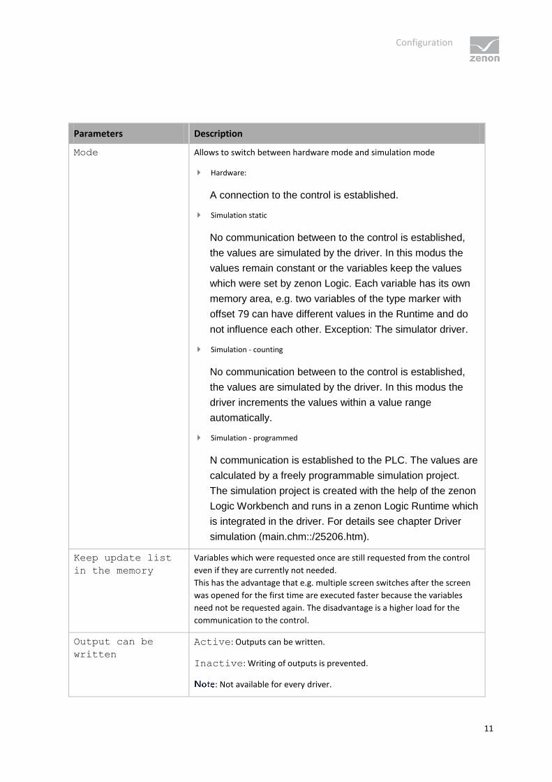
Parameters Description
Mode Allows to switch between hardware mode and simulation mode
Hardware:
A connection to the control is established.
Simulation static
No communication between to the control is established,
the values are simulated by the driver. In this modus the
values remain constant or the variables keep the values
which were set by zenon Logic. Each variable has its own
memory area, e.g. two variables of the type marker with
offset 79 can have different values in the Runtime and do
not influence each other. Exception: The simulator driver.
Simulation - counting
No communication between to the control is established,
the values are simulated by the driver. In this modus the
driver increments the values within a value range
automatically.
Simulation - programmed
N communication is established to the PLC. The values are
calculated by a freely programmable simulation project.
The simulation project is created with the help of the zenon
Logic Workbench and runs in a zenon Logic Runtime which
is integrated in the driver. For details see chapter Driver
simulation (main.chm::/25206.htm).
Keep update list
in the memory
Variables which were requested once are still requested from the control
even if they are currently not needed.
This has the advantage that e.g. multiple screen switches after the screen
was opened for the first time are executed faster because the variables
need not be requested again. The disadvantage is a higher load for the
communication to the control.
Output can be
written
Active: Outputs can be written.
Inactive: Writing of outputs is prevented.
: Not available for every driver.

Configuration
12
Variable image
remanent
This option saves and restores the current value, time stamp and the states
of a data point.
Fundamental requirement: The variable must have a valid value and time
stamp.
The variable image is saved in mode hardware if:
one of the states S_MERKER_1(0) up to S_MERKER8(7), REVISION(9), AUS(20)
or ERSATZWERT(27) is active
The variable image is always saved if:
the variable is of the object type Driver variable
the driver runs in simulation mode. (not programmed simulation)
The following states are not restored at the start of the Runtime:
SELECT(8)
WR-ACK(40)
WR-SUC(41)
The mode Simulation - programmed at the driver start is not a
criterion in order to restore the remanent variable image.
Stop at the
Standby Server
Setting for redundancy at drivers which allow only on
communication connection. For this the driver is stopped at the
Standby Server and only started at the upgrade.
If this option is active, the gapless archiving is no longer
guaranteed.
Active: Sets the driver at the not-process-leading Server
automatically in a stop-like state. In contrast to stopping via driver
command, the variable does not receive status switched off
(statusverarbeitung.chm::/24150.htm) but an empty value. This
prevents that at the upgrade to the Server irrelevant values are
created in the AML, CEL and Historian.
Global Update time Active: The set Global update time in ms is used for all
variables in the project. The priority set at the variables is not used.
Inactive: The set priorities are used for the individual variables.
Priority Here you set the polling times for the individual priorities. All variables with
the according priority are polled in the set time. The allocation is taken
Configuration
13
place for each variable separately in the settings of the variable properties.
The communication of the individual variables are graduated in respect of
importance or necessary topicality using the priorities. Thus the
communication load is distributed better.
UPDATE TIME FOR CYCLICAL DRIVER
The following applies for cyclical drivers:
For Set value, Advising of variables and Requests, a read cycle is immediately triggered for all drivers -
regardless of the set update time. This ensures that the value is immediately available for visualization after
writing. Update times can therefore be shorter than pre-set for cyclical drivers.
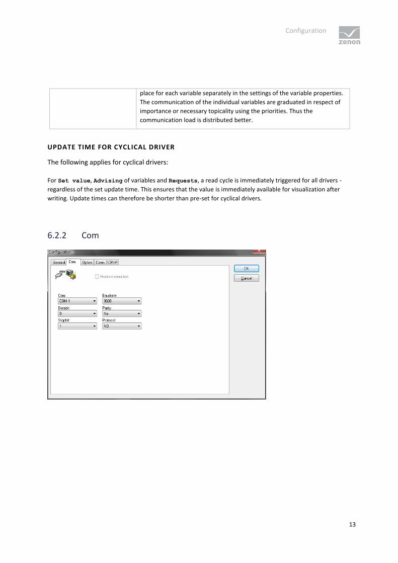
6.2.2 Com

Configuration
14
Parameters Description
Com Select serial interface COM1 - COM64
Data bit Data word size in Bit: 5,6,7,8
Stop bit 1, 1.5, 2
Baud rate Data transfer rate
110; 300; 1200; 2400; 4800; 9600; 19200; 38400; 57600; 115200
Parity even/uneven/none
Protocol RTS/CTS/none
DEFAULT CONFIGURATION
Parameters Description
Com COM1
Baud rate Adjust after setting on PLC
Data bit 8
Stop bit 1
Parity Adjust after setting on PLC
Protocol NO
Configuration
15
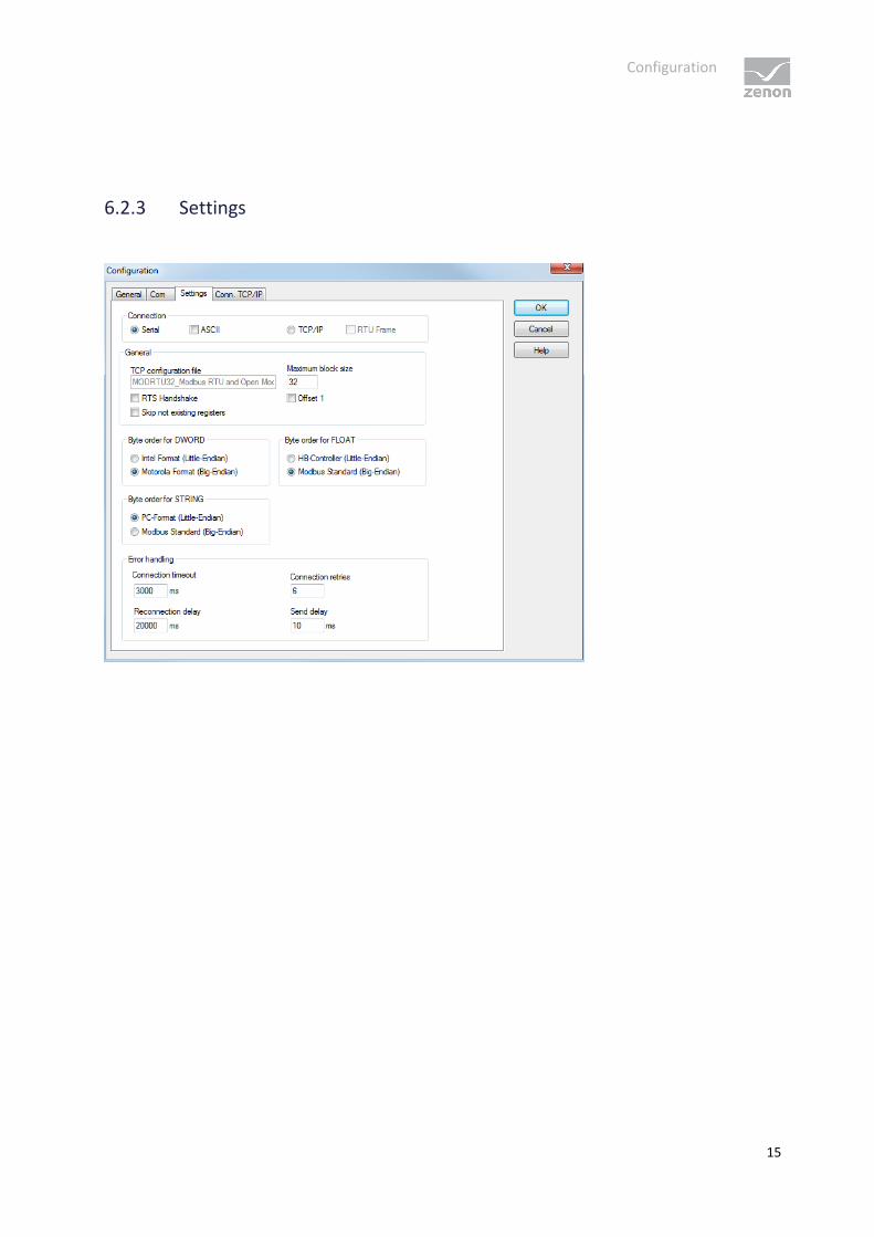
6.2.3 Settings

Configuration
16
Parameters Description
Connection Definition of which connection is used.
Serial For serial mode, both Modbus RTU and Modbus ASCII can be
selected.
ASCII Active: The driver communicates using the Modbus ASCII protocol.
Inactive: The driver communicates using Modbus RTU.
TCP/IP Requires a configuration file. This file stores the TCP/IP settings.
RTU Frame Active: Serial information is transferred to the TCP protocol exactly.
General General settings.
TCP configuration file The name of the TCP configuration file is defined here.
Default: MODRTU32_[Treiberbezeichnung].txt
Maximum block size Maximum block size of a data telegram in WORDs.
: Block size must be less than 64. (1-
125, Default 32)
RTS Handshake Some PLCs need the RTS handshake for
correct communication.
Offset 1 The "Offset 1" affects the addressing of all variables.
Active: The driver subtracts 1 when the variable addresses (coils,
register) are sent and adds 1 when they are received.
Skip non-existent tabs The driver reads data in a block. If there is no data between two address
areas close to each other, the driver will still try to access these non-
existent areas. This option will avoid that.
Byte sequence for DWORD Defines the sequence of lower-value and higher-value words for double
word objects (DINT/UDINT). You can choose between Motorola (Big-
Endian) and Intel (Little-Endian).
Motorola Format (Big-
Endian)
Active: DWORD ordering in accordance with Motorola format.
Intel Format (Little-
Endian)
Active: DWORD ordering in accordance with Intel format.
Byte sequence for FLOAT Defines the sequence of lower-value and higher-value words for FLOAT
objects (REAL). You can choose between Modbus Standard (Big-Endian)
and HB-Controller (Little-Endian).

Configuration
17
Modbus Standard (Big-
Endian)
Active: Float ordering in accordance with Modbus standard.
HB Controller Float
(Little-Endian)
Active: Float ordering in accordance with HB controller.
Byte sequence for STRING Defines display of the byte sequence.
If there is relevant information in the documentation of a PLC the
following is usually applicable: MSB-first = Motorola = Big-Endian =
Modbus. And: Intel = Little-Endian = PC. This can be handled differently in
some documentation however.
Modbus Standard (Big-
Endian)
Active: Display in accordance with Modbus standard with switched
characters.
PC Format (Little-
Endian)
Active: Display in PC format with ascending sequence.
Troubleshooting
Connection timeout Time in milliseconds to wait for a response from the slave. A
communication error will be displayed if there is no response within this
time.
Only available with serial connection. For a TCP/IP connection, the setting
for the Timeout [s] property in the Network node is used for the
connection time-out. (24 seconds for XP systems, for example)
The communication time-out time must at any rate be
higher than the maximum response time of the Modbus RTU slave.
Otherwise misinterpretation of the responses can occur.
Default: 3000 ms
Retries on error Number of send repetitions when there is no answer from the slave after
the set communication time-out.
1: a connection attempt, no repetitions
0: constant repetition
Default: 6
Delay after connection
termination
Time in milliseconds to wait after a communication error has occured
before trying to re-establish the connection.
Default: 20000 ms
Send delay Time delay in milliseconds for "send" orders. Affects the whole driver.

Configuration
18
Can only be selected with a serial connection.
OK Applies changes and closes dialog.
Cancel Discards changes and closes dialog.
Help Opens online help.
TIME OUT BEHAVIOR
With TCP connections, the communication time out is predefined by the system-dependent Timeout
[s].
After the timeout has expired, the driver attempts - with default settings - to send the request again up
to 5 times. If these 5 attempts are not successful, no additional attempt to connect is made during the
reconnect time out.
With serial connection the times from the driver configuration are used for the time out behavior. The
sent delay time must pass before a request is sent. After a request has been sent, the time period which
is waited for an answer is as long as the connection timeout. If there is no answer in this time period,
the request is sent again up to 5 times. (a default of 6 means 5 additional attempts). After that no new
connection establishment is tried for the set reconnect time out. See also the following graphic.
Configuration
19
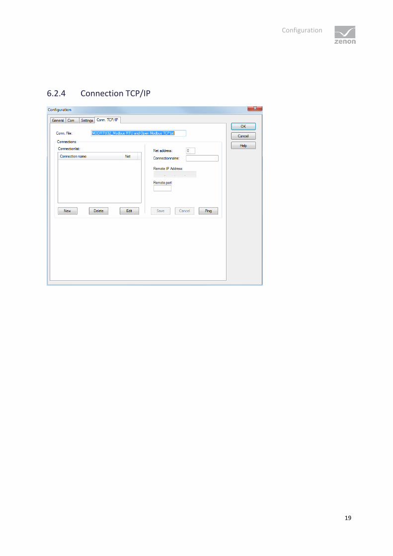
6.2.4 Connection TCP/IP

Configuration
20
Parameters Description
Connection file Name of the file in which the settings for each of the TCP/IP participants are
saved.
Display only. Changes to the file name are made in the Options (on page 15)
tab.
Connections Settings of the connections.
Connection list List of defined connections to PLCs.
Net address Each connection is assigned a network address. This must correspond to the
settings in the Net address property of the variable definition.
The Net address property for the variables must be set to 0 for
serial communication.
Connection name Name of the connection as it is displayed in the connection list.
Remote IP address Address of the PLC.
Remote port Port address of PLC. You can find details in the manual of your PLC.
Standard port: 502
New Establishes a new connection.
Delete Deletes highlighted connection from the list.
Edit Opens highlighted connection for editing.
Save Accepts all changes for edited connection and closes editing option.
Cancel Discards all changes for edited connection and closes editing option.
Ping Sends a ping to the IP address that is configured for this connection. Allows the
connection to the device to b tested. If the ping is concluded negatively, check
the IP address and check to see if the device is online.
OK Accept changes in the dialog and close dialog.
Only available if no connection is in the "edit" state.
Cancel Discards all changes and closes dialog.
Help Opens online help.
CREATE NEW CONNECTION
1. click on the button New

Creating variables
21
2. Enter the connection details.
3. Click on Save
EDIT CONNECTION
1. select the connection in the connection list
2. click on the button Edit
3. change the connection parameters
4. finish with Save
DELETE CONNECTION
1. select the connection in the connection list
2. click on the button Delete
3. the connection will be removed from the list
7. Creating variables
This is how you can create variables in the zenon Editor:
7.1 Creating variables in the Editor
Variables can be created:
as simple variables
in arrays main.chm::/15262.htm
as structure variables main.chm::/15278.htm

Creating variables
22
VARIABLE DIALOG
To create a new variable, regardless of which type:
1. Select the New variable command in the Variables node in the context menu
2. The dialog for configuring variables is opened
3. configure the variable

Creating variables
23
4. The settings that are possible depends on the type of variables
Property Description
Name Distinct name of the variable. If a variable with the same name already
exists in the project, no additional variable can be created with this name.
The # character is not permitted in variable names. If non-
permitted characters are used, creation of variables cannot be completed
and the Finish button remains inactive.
Drivers Select the desired driver from the drop-down list.
If no driver has been opened in the project, the driver for internal
variables (Intern.exe (Main.chm::/Intern.chm::/Intern.htm)) is
automatically loaded.
Driver object type
(cti.chm::/28685.h
tm)
Select the appropriate driver object type from the drop-down list.

Creating variables
24
Data type Select the desired data type. Click on the ... button to open the selection
dialog.
Array settings Expanded settings for array variables. You can find details in the Arrays
chapter.
Addressing options Expanded settings for arrays and structure variables. You can find details
in the respective section.
Automatic element
activation
Expanded settings for arrays and structure variables. You can find details
in the respective section.
INHERITANCE FROM DATA TYPE
Measuring range, Signal range and Set value are always:
derived from the datatype
Automatically adapted if the data type is changed
If a change is made to a data type that does not support the set signal range, the
signal range is amended automatically. For example, for a change from INT to SINT, the signal
range is changed to 127. The amendment is also carried out if the signal range was not inherited from
the data type. In this case, the measuring range must be adapted manually.
7.2 Addressing

Creating variables
25
Property Description
Name Any name can be chosen; the name must be unique within each
project.
Identificat
ion
Any text can be entered here, e.g. for resource labels, comments ...
Net address Bus address or net address of the variable.
When using serial communication, this address corresponds to the Modbus address of
the PLC; for communication via Ethernet, it corresponds to the connection
configuration in the driver. This defines the PLC/connection on which the variable
resides.
If a gateway (TCP/IP) is used for communicating with the Modbus stations, you
have to create a separate TCP/IP connection for each Modbus station. Use the
address of the gateway as the IP address and the address of the Modbus station
as the Net address of the connection and in the variables.
The highest possible Modbus address, according to the protocol specification, is 247.
The address 0 is used for broadcast messages (write only).
Data block not used for this driver
Offset Offset of the variable; the memory address of the variable in the PLC. Configurable [0..
4294967295]
Alignment The driver uses word-based addressing (16 bit). If only one Byte is read, you can
configure here whether the HiByte or the LowByte will be addressed.
Bit number Number of the bit within the configured offset.
Valid input [0.. 65535] Working range [0-15]
String
length
Only available for String variables: Maximum number of characters that the variable can
take.
Driver
object type
Depending on the employed driver, an object type is selected during the creation of the
variable; the type can be changed here later.
Data type Data type of the variable, which is selected during the creation of the variable; the type
can be changed here later.
ATTENTION: If you change the data type later, all other properties of the variable must
be checked and adjusted, if necessary.

Creating variables
26
7.3 Driver objects and datatypes
Driver objects are areas available in the PLC, such as markers, data blocks etc. Here you can find out
which driver objects are provided by the driver and which IEC data types can be assigned to the
respective driver objects.
7.3.1 Driver objects
The following object types are available in this driver:

Creating variables
27
Driver- object type
Channel type
Read: Modbus function (hex/dec code)
Write: Modbus function (hex/dec code)
Supported data types
Comment
Holding
Register
8 0x03 / 3 0x10 / 16 REAL, LREAL,
BOOL, DINT,
UDINT,
USINT, INT,
UINT, SINT,
STRING
Class 0 - multiple register.
Linear addressing:
Bit: one-step via offset
and bit number
Byte (8 bits): one-step via
offset and
orientation
Word (16 bits)
Double word (32 bits)
Float (32 bits)
String(n*Byte):
one-step via offset
Coil 65 0x01 / 1 0x05 / 5 BOOL Class 1 - coil.
Linear addressing one-step via
offset.
Input
status
66 0x02/2 N/A BOOL Class 1 - input discretes.
Linear addressing one-step via
offset.
Analog
Input
10 0x04 / 4 N/A REAL, LREAL,
BOOL, DINT,
UDINT,
USINT, INT,
UINT, SINT,
STRING
Class 1 - input register.
Linear addressing as with
holding register.
Preset
Single
Register
(FC 6)
67 N/A 0x06 / 6 UINT Class 1 - single register.
Alarm
stack
97 0x03 / 3 N/A STRING Read special events from
Secheron PLC.

Creating variables
28
Addressing:
Event type = data
block
Sub-type = offset.
Device
status
24 0x11 / 17 N/A BOOL, USINT PLC specific.
Device
identific
ation
68 0x2B / 43 N/A STRING PLC specific.
Driver
variable
35 Y Y BOOL, SINT,
USINT, INT,
UINT, DINT,
UDINT, REAL,
STRING
Variables for the statistical
analysis of communication.
Transfers between
Runtime and driver not to the
PLC.
Find out more in the chapter
about the Driver variables (on
page 37)

Creating variables
29
MODBUS FUNCTION CODES
Function code hex/dec
Modbus identifier Comment
0x01 / 1 Read coils This function code is used to read from 1 to 2000 contiguous
status of coils (bits) in a remote device
0x02/2 Read discrete inputs This function code is used to read from 1 to 2000 contiguous
status of discrete inputs (bits) in a remote device
0x03 / 3 Read multiple registers This function code is used to read a block of contiguous
holding registers (1 to 125 words) in a remote device.
0x04 / 4 Read input registers This function code is used to read a block of contiguous input
registers (1 to 125 words) in a remote device.
0x05 / 5 Write coil This function code is used to write a single output (one bit) to
either ON or OFF in a remote device.
0x06 / 6 Write single register This function code is used to write a single (one word)
holding register in a remote device.
0x10 / 16 Write multiple registers This function code is used to write a block of contiguous
holding registers (1 to approx. 120 words) in a remote device.
0x11 / 17 Report Slave ID This function code is used to read the description of the type,
the current status, and other information specific to a
remote device.
0x2B / 43 Read Device Identification This function code allows reading the identification and
additional information relative to the physical and functional
description of a remote device.
7.3.2 Mapping of the data types
All variables in zenon are derived from IEC data types. The following table compares the IEC datatypes
with the datatypes of the PLC.
Creating variables
30
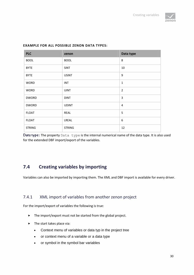
EXAMPLE FOR ALL POSSIBLE ZENON DATA TYPES:
PLC zenon Data type
BOOL BOOL 8
BYTE SINT 10
BYTE USINT 9
WORD INT 1
WORD UINT 2
DWORD DINT 3
DWORD UDINT 4
FLOAT REAL 5
FLOAT LREAL 6
STRING STRING 12
The property Data type is the internal numerical name of the data type. It is also used
for the extended DBF import/export of the variables.
7.4 Creating variables by importing
Variables can also be imported by importing them. The XML and DBF import is available for every driver.
7.4.1 XML import of variables from another zenon project
For the import/export of variables the following is true:
The import/export must not be started from the global project.
The start takes place via:
Context menu of variables or data typ in the project tree
or context menu of a variable or a data type
or symbol in the symbol bar variables

Creating variables
31
Attention
When importing/overwriting an existing data type, all variables based on the existing
data type are changed.
There is a data type XYZ derived from the type INTwith variables based on this data
type. The XML file to be imported also contains a data type with the name XYZ but
derived from type STRING. If this data type is imported, the existing data type is
overwritten and the type of all variables based on it is adjusted. I.e. the variables are now
no longer INT variables, but STRING variables.
7.4.2 DBF Import/Export
Data can be exported to and imported from dBase.
IMPORT DBF FILE
To start the import:
1. right-click on the variable list
2. in the drop-down menu of Extended export/import... select the Import dBase command
3. follow the import assistant
The format of the file is described in the chapter File structure.
Info
Note:
Driver object type and data type must be amended to the target driver in the DBF file in order for
variables to be imported.
dBase does not support structures or arrays (complex variables) at import.

Creating variables
32
EXPORT DBF FILE
To start the export:
1. right-click on the variable list
2. in the drop-down menu of Extended export/import... select the Export dBase command
3. follow the export assistant
Attention
DBF files:
must correspond to the 8.3 DOS format for filenames (8 alphanumeric characters for name, 3
character suffix, no spaces)
must not have dots (.) in the path name.
e.g. the path C:\users\John.Smith\test.dbf is invalid.
Valid: C:\users\JohnSmith\test.dbf
must be stored close to the root directory in order to fulfill the limit for file name length including
path: maximum 255 characters
The format of the file is described in the chapter File structure.
Info
dBase does not support structures or arrays (complex variables) at export.
File structure of the dBase export file
The dBaseIV file must have the following structure and contents for variable import and export:
Creating variables
33
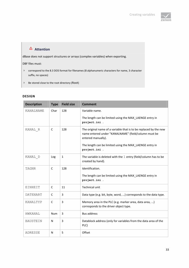
Attention
dBase does not support structures or arrays (complex variables) when exporting.
DBF files must:
correspond to the 8.3 DOS format for filenames (8 alphanumeric characters for name, 3 character
suffix, no spaces)
Be stored close to the root directory (Root)
DESIGN
Description Type Field size Comment
KANALNAME Char 128 Variable name.
The length can be limited using the MAX_LAENGE entry in
project.ini .
KANAL_R C 128 The original name of a variable that is to be replaced by the new
name entered under "KANALNAME" (field/column must be
entered manually).
The length can be limited using the MAX_LAENGE entry in
project.ini .
KANAL_D Log 1 The variable is deleted with the 1 entry (field/column has to be
created by hand).
TAGNR C 128 Identification.
The length can be limited using the MAX_LAENGE entry in
project.ini .
EINHEIT C 11 Technical unit
DATENART C 3 Data type (e.g. bit, byte, word, ...) corresponds to the data type.
KANALTYP C 3 Memory area in the PLC (e.g. marker area, data area, ...)
corresponds to the driver object type.
HWKANAL Num 3 Bus address
BAUSTEIN N 3 Datablock address (only for variables from the data area of the
PLC)
ADRESSE N 5 Offset
Creating variables
34
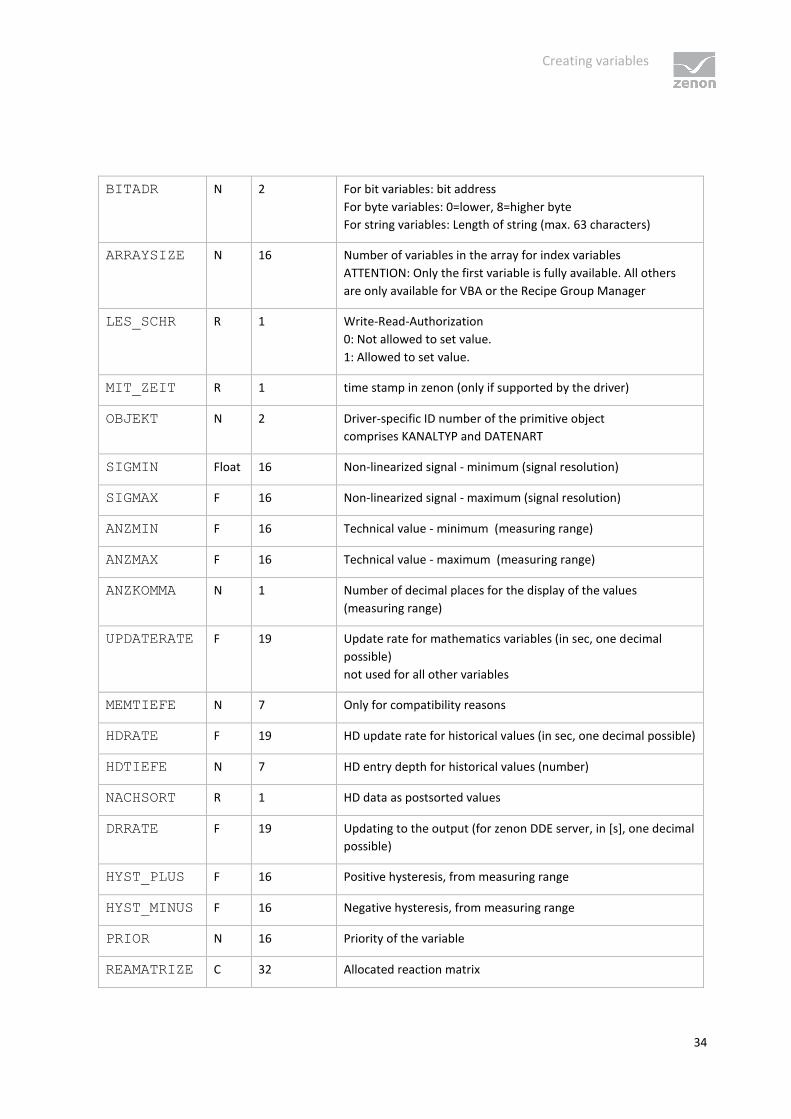
BITADR N 2 For bit variables: bit address
For byte variables: 0=lower, 8=higher byte
For string variables: Length of string (max. 63 characters)
ARRAYSIZE N 16 Number of variables in the array for index variables
ATTENTION: Only the first variable is fully available. All others
are only available for VBA or the Recipe Group Manager
LES_SCHR R 1 Write-Read-Authorization
0: Not allowed to set value.
1: Allowed to set value.
MIT_ZEIT R 1 time stamp in zenon (only if supported by the driver)
OBJEKT N 2 Driver-specific ID number of the primitive object
comprises KANALTYP and DATENART
SIGMIN Float 16 Non-linearized signal - minimum (signal resolution)
SIGMAX F 16 Non-linearized signal - maximum (signal resolution)
ANZMIN F 16 Technical value - minimum (measuring range)
ANZMAX F 16 Technical value - maximum (measuring range)
ANZKOMMA N 1 Number of decimal places for the display of the values
(measuring range)
UPDATERATE F 19 Update rate for mathematics variables (in sec, one decimal
possible)
not used for all other variables
MEMTIEFE N 7 Only for compatibility reasons
HDRATE F 19 HD update rate for historical values (in sec, one decimal possible)
HDTIEFE N 7 HD entry depth for historical values (number)
NACHSORT R 1 HD data as postsorted values
DRRATE F 19 Updating to the output (for zenon DDE server, in [s], one decimal
possible)
HYST_PLUS F 16 Positive hysteresis, from measuring range
HYST_MINUS F 16 Negative hysteresis, from measuring range
PRIOR N 16 Priority of the variable
REAMATRIZE C 32 Allocated reaction matrix

Creating variables
35
ERSATZWERT F 16 Substitute value, from measuring range
SOLLMIN F 16 Minimum for set value actions, from measuring range
SOLLMAX F 16 Maximum for set value actions, from measuring range
VOMSTANDBY R 1 Get value from standby server; the value of the variable is not
requested from the server but from the standby-server in
redundant networks
RESOURCE C 128 Resource label.
Free string for export and display in lists.
The length can be limited using the MAX_LAENGE entry in
project.ini .
ADJWVBA R 1 Non-linear value adaption:
0: Non-linear value adaption is used
1: non linear value adaption is not used
ADJZENON C 128 Linked VBA macro for reading the variable value for non-linear
value adjustment.
ADJWVBA C 128 Linked VBA macro for writing the variable value for non-linear
value adjustment.
ZWREMA N 16 Linked counter REMA.
MAXGRAD N 16 Gradient overflow for counter REMA.
Attention.
When importing, the driver object type and data type must be amended to the target
driver in the DBF file in order for variables to be imported.
LIMIT DEFINITION
Limit definition for limit values 1 to 4, and status 1 to 4:

Creating variables
36
Description Type Field size Comment
AKTIV1 R 1 Limit value active (per limit value available)
GRENZWERT1 F 20 Technical value or ID number of a linked variable for a dynamic
limit (see VARIABLEx)
(if VARIABLEx is 1 and here it is -1, the existing variable linkage
is not overwritten)
SCHWWERT1 F 16 Threshold value for limit
HYSTERESE1 F 14 Hysteresis in %
BLINKEN1 R 1 Set blink attribute
BTB1 R 1 Logging in CEL
ALARM1 R 1 Alarm
DRUCKEN1 R 1 Printer output (for CEL or Alarm)
QUITTIER1 R 1 Must be acknowledged
LOESCHE1 R 1 Must be deleted
VARIABLE1 R 1 Dyn. limit value linking
the limit is defined by an absolute value (see field GRENZWERTx).
FUNC1 R 1 Function linking
ASK_FUNC1 R 1 With interrogation before execution
FUNC_NR1 N 10 ID number of the linked function
(if “-1” is entered here, the existing function is not overwritten
during import)
A_GRUPPE1 N 10 Alarm/event group
A_KLASSE1 N 10 Alarm/event class
MIN_MAX1 C 3 Minimum, Maximum
FARBE1 N 10 Color as Windows coding
GRENZTXT1 C 66 Limit value text
A_DELAY1 N 10 Time delay
INVISIBLE1 R 1 Invisible
Expressions in the column "Comment" refer to the expressions used in the dialog boxes for the
definition of variables. For more information, see chapter Variable definition.

Creating variables
37
7.5 Driver variables
The driver kit implements a number of driver variables. These are divided into:
Information
Configuration
Statistics and
Error messages
The definitions of the variables defined in the driver kit are available in the import file drvvar.dbf (on
the CD in the directory: CD_Drive:/Predefined/Variables) and can be imported from there.
Variable names must be unique in zenon. If driver variables are to be imported from drvvar.dbf
again, the variables that were imported beforehand must be renamed.
Info
Not every driver supports all driver variants.
For example:
Variables for modem information are only supported by modem-compatible drivers
Driver variables for the polling cycle only for pure polling drivers
Connection-related information such as ErrorMSG only for drivers that only edit one connection at
a a time
Creating variables
38
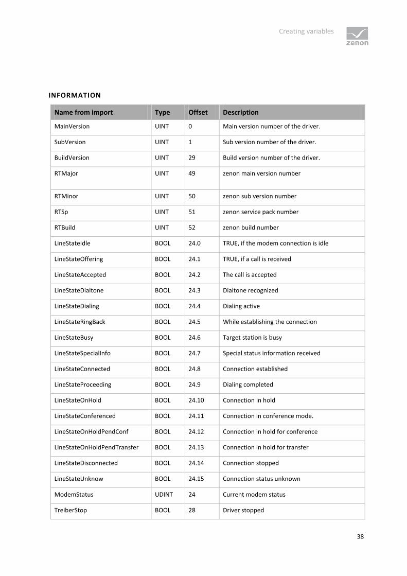
INFORMATION
Name from import Type Offset Description
MainVersion UINT 0 Main version number of the driver.
SubVersion UINT 1 Sub version number of the driver.
BuildVersion UINT 29 Build version number of the driver.
RTMajor UINT 49 zenon main version number
RTMinor UINT 50 zenon sub version number
RTSp UINT 51 zenon service pack number
RTBuild UINT 52 zenon build number
LineStateIdle BOOL 24.0 TRUE, if the modem connection is idle
LineStateOffering BOOL 24.1 TRUE, if a call is received
LineStateAccepted BOOL 24.2 The call is accepted
LineStateDialtone BOOL 24.3 Dialtone recognized
LineStateDialing BOOL 24.4 Dialing active
LineStateRingBack BOOL 24.5 While establishing the connection
LineStateBusy BOOL 24.6 Target station is busy
LineStateSpecialInfo BOOL 24.7 Special status information received
LineStateConnected BOOL 24.8 Connection established
LineStateProceeding BOOL 24.9 Dialing completed
LineStateOnHold BOOL 24.10 Connection in hold
LineStateConferenced BOOL 24.11 Connection in conference mode.
LineStateOnHoldPendConf BOOL 24.12 Connection in hold for conference
LineStateOnHoldPendTransfer BOOL 24.13 Connection in hold for transfer
LineStateDisconnected BOOL 24.14 Connection stopped
LineStateUnknow BOOL 24.15 Connection status unknown
ModemStatus UDINT 24 Current modem status
TreiberStop BOOL 28 Driver stopped

Creating variables
39
For driver stop, the variable has the value
TRUE and an OFF bit. After the driver has
started, the variable has the value FALSE and
no OFF bit.
SimulRTState UDINT 60 Informs the status of Runtime for driver
simulation.
CONFIGURATION
Name from import Type Offset Description
ReconnectInRead BOOL 27 If TRUE, the modem is automatically
reconnected for reading
ApplyCom BOOL 36 Apply changes in the settings of the serial
interface. Writing to this variable
immediately results in the method
SrvDrvVarApplyCom being called (which
currently has no further function).
ApplyModem BOOL 37 Apply changes in the settings of the
modem. Writing this variable immediately
calls the method SrvDrvVarApplyModem.
This closes the current connection and
opens a new one according to the settings
PhoneNumberSet and ModemHwAdrSet.
PhoneNumberSet STRING 38 Telephone number, that should be used
ModemHwAdrSet DINT 39 Hardware address for the telephone
number
GlobalUpdate UDINT 3 Update time in milliseconds (ms).
BGlobalUpdaten BOOL 4 TRUE, if update time is global
TreiberSimul BOOL 5 TRUE, if driver in sin simulation mode
TreiberProzab BOOL 6 TRUE, if the variables update list should be
kept in the memory
ModemActive BOOL 7 TRUE, if the modem is active for the driver

Creating variables
40
Device STRING 8 Name of the serial interface or name of the
modem
ComPort UINT 9 Number of the serial interface.
Baud rate UDINT 10 Baud rate of the serial interface.
Parity SINT 11 Parity of the serial interface
ByteSize SINT 14 Number of bits per character of the serial
interface
Value = 0 if the driver cannot establish any
serial connection.
StopBit SINT 13 Number of stop bits of the serial interface.
Autoconnect BOOL 16 TRUE, if the modem connection should be
established automatically for
reading/writing
PhoneNumber STRING 17 Current telephone number
ModemHwAdr DINT 21 Hardware address of current telephone
number
RxIdleTime UINT 18 Modem is disconnected, if no data transfer
occurs for this time in seconds (s)
WriteTimeout UDINT 19 Maximum write duration for a modem
connection in milliseconds (ms).
RingCountSet UDINT 20 Number of ringing tones before a call is
accepted
ReCallIdleTime UINT 53 Waiting time between calls in seconds (s).
ConnectTimeout UDINT 54 Time in seconds (s) to establish a
connection.
Creating variables
41
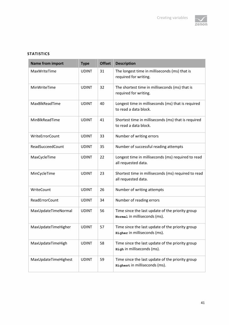
STATISTICS
Name from import Type Offset Description
MaxWriteTime UDINT 31 The longest time in milliseconds (ms) that is
required for writing.
MinWriteTime UDINT 32 The shortest time in milliseconds (ms) that is
required for writing.
MaxBlkReadTime UDINT 40 Longest time in milliseconds (ms) that is required
to read a data block.
MinBlkReadTime UDINT 41 Shortest time in milliseconds (ms) that is required
to read a data block.
WriteErrorCount UDINT 33 Number of writing errors
ReadSucceedCount UDINT 35 Number of successful reading attempts
MaxCycleTime UDINT 22 Longest time in milliseconds (ms) required to read
all requested data.
MinCycleTime UDINT 23 Shortest time in milliseconds (ms) required to read
all requested data.
WriteCount UDINT 26 Number of writing attempts
ReadErrorCount UDINT 34 Number of reading errors
MaxUpdateTimeNormal UDINT 56 Time since the last update of the priority group
Normal in milliseconds (ms).
MaxUpdateTimeHigher UDINT 57 Time since the last update of the priority group
Higher in milliseconds (ms).
MaxUpdateTimeHigh UDINT 58 Time since the last update of the priority group
High in milliseconds (ms).
MaxUpdateTimeHighest UDINT 59 Time since the last update of the priority group
Highest in milliseconds (ms).
Driver-specific functions
42
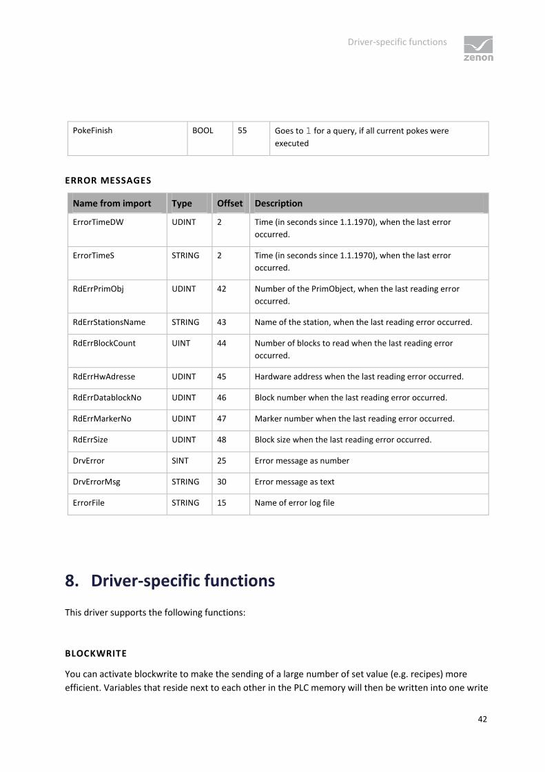
PokeFinish BOOL 55 Goes to 1 for a query, if all current pokes were
executed
ERROR MESSAGES
Name from import Type Offset Description
ErrorTimeDW UDINT 2 Time (in seconds since 1.1.1970), when the last error
occurred.
ErrorTimeS STRING 2 Time (in seconds since 1.1.1970), when the last error
occurred.
RdErrPrimObj UDINT 42 Number of the PrimObject, when the last reading error
occurred.
RdErrStationsName STRING 43 Name of the station, when the last reading error occurred.
RdErrBlockCount UINT 44 Number of blocks to read when the last reading error
occurred.
RdErrHwAdresse UDINT 45 Hardware address when the last reading error occurred.
RdErrDatablockNo UDINT 46 Block number when the last reading error occurred.
RdErrMarkerNo UDINT 47 Marker number when the last reading error occurred.
RdErrSize UDINT 48 Block size when the last reading error occurred.
DrvError SINT 25 Error message as number
DrvErrorMsg STRING 30 Error message as text
ErrorFile STRING 15 Name of error log file
8. Driver-specific functions
This driver supports the following functions:
BLOCKWRITE
You can activate blockwrite to make the sending of a large number of set value (e.g. recipes) more
efficient. Variables that reside next to each other in the PLC memory will then be written into one write

Driver commands
43
telegram; for larger areas, the variables will be packed into a few telegrams instead of writing every
single variable.
Activating blockwrite
The following entry must be added to the project.ini :
[MODRTU32]
BLOCKWRITE=1
TRANSACTION IDENTIFICATION
The driver increases the transaction identifier for each packet sent and expects a response from the
slave with the same identifier or 0.
9. Driver commands
This chapter describes standard functions that are valid for most zenon drivers. Not all functions
described here are available for every driver. For example, a driver that does not, according to the data
sheet, support a modem connection also does not have any modem functions.
Driver commands are used to influence drivers using zenon; start and stop for example.
The engineering is implemented with the help of function Driver commands. To do this:
create a new function
select Variables -> Driver commands

Driver commands
44
The dialog for configuration is opened
Parameters Description
Drivers Drop-down list with all drivers which are loaded in the project.
Current state Fixed entry which has no function in the current version.
Driver commands Drop-down list for the selection of the command.
Start driver (online
mode)
Driver is reinitialized and started.
Stop driver (offline
mode)
Driver is stopped. No new data is accepted.
If the driver is in offline mode, all variables that were
created for this driver receive the status switched off
(OFF; Bit 20).
Driver in simulation
mode
Driver is set into simulation mode.
The values of all variables of the driver are simulated by the
driver. No values from the connected hardware (e.g. PLC, bus
system, ...) are displayed.
Driver in hardware
mode
Driver is set into hardware mode.
For the variables of the driver the values from the connected
hardware (e.g. PLC, bus system, ...) are displayed.
Driver-specific
command
Enter driver-specific commands. Opens input field in order to
enter a command.
Activate driver write
set value
Write set value to a driver is allowed.
Deactivate driver Write set value to a driver is prohibited.

Error analysis
45
write set value
Establish connection
with modem
Establish connection (for modem drivers) Opens the input fields
for the hardware address and for the telephone number.
Disconnect from modem Terminate connection (for modem drivers)
Show this dialog in the
Runtime
The dialog is shown in Runtime so that changes can be made.
If the computer, on which the driver command function is executed, is part of the zenon network,
additional actions are carried out. A special network command is sent from the computer to the project
server, which then executes the desired action on its driver. In addition, the Server sends the same
driver command to the project standby. The standby also carries out the action on its driver.
This makes sure that Server and Standby are synchronized. This only works if the Server and the Standby
both have a working and independent connection to the hardware.
10. Error analysis
Should there be communication problems, this chapter will assist you in finding out the error.
10.1 Analysis tool
All zenon modules such as Editor, Runtime, drivers, etc. write messages to a joint log file. To display
them correctly and clearly, use the Diagnosis Viewer (main.chm::/12464.htm) program that was also
installed with zenon. You can find it under Start/All programs/zenon/Tools 7.00 -> Diagviewer.
zenon driver log all errors in the log files. The default folder for the log files is subfolder LOG in directory
ProgramData, example: C:\ProgramData\zenon \zenon700\LOG for zenon version 7.00
SP0. Log files are text files with a special structure.

Error analysis
46
With the default settings, a driver only logs error information. With the Diagnosis Viewer
you can enhance the diagnosis level for most of the drivers to "Debug" and "Deep Debug". With this the
driver also logs all other important tasks and events.
In the Diagnosis Viewer you can also:
follow currently created entries live
customize the logging settings
change the folder in which the log files are saved
1. In Windows CE even errors are not logged per default due to performance reasons.
2. The Diagnosis Viewer displays all entries in UTC (coordinated world time) and not in local time.
3. The Diagnosis Viewer does not display all columns of a log file per default. To display more
columns activate property Add all columns with entry in the context menu of the column
header.
4. If you only use Error logging, the problem description is in column Error text. For other
diagnosis level the description is in column General text.
5. For communication problems many drivers also log error numbers which the PLC assigns to
them. They are displayed in Error text and/or Error code and/or Driver error
parameter(1 and 2). Hints on the meaning of error codes can be found in the driver
documentation and the protocol/PLC description.
6. At the end of your test set back the diagnosis level from Debug or Deep Debug. At Debug and
Deep Debug there are a great deal of data for logging which are saved to the hard drive and
which can influence your system performance. They are still logged even after you close the
Diagnosis Viewer.
Info
You can find further information on the Diagnosis Viewer in the Diagnose Viewer
(main.chm::/12464.htm) chapter.
Error analysis
47
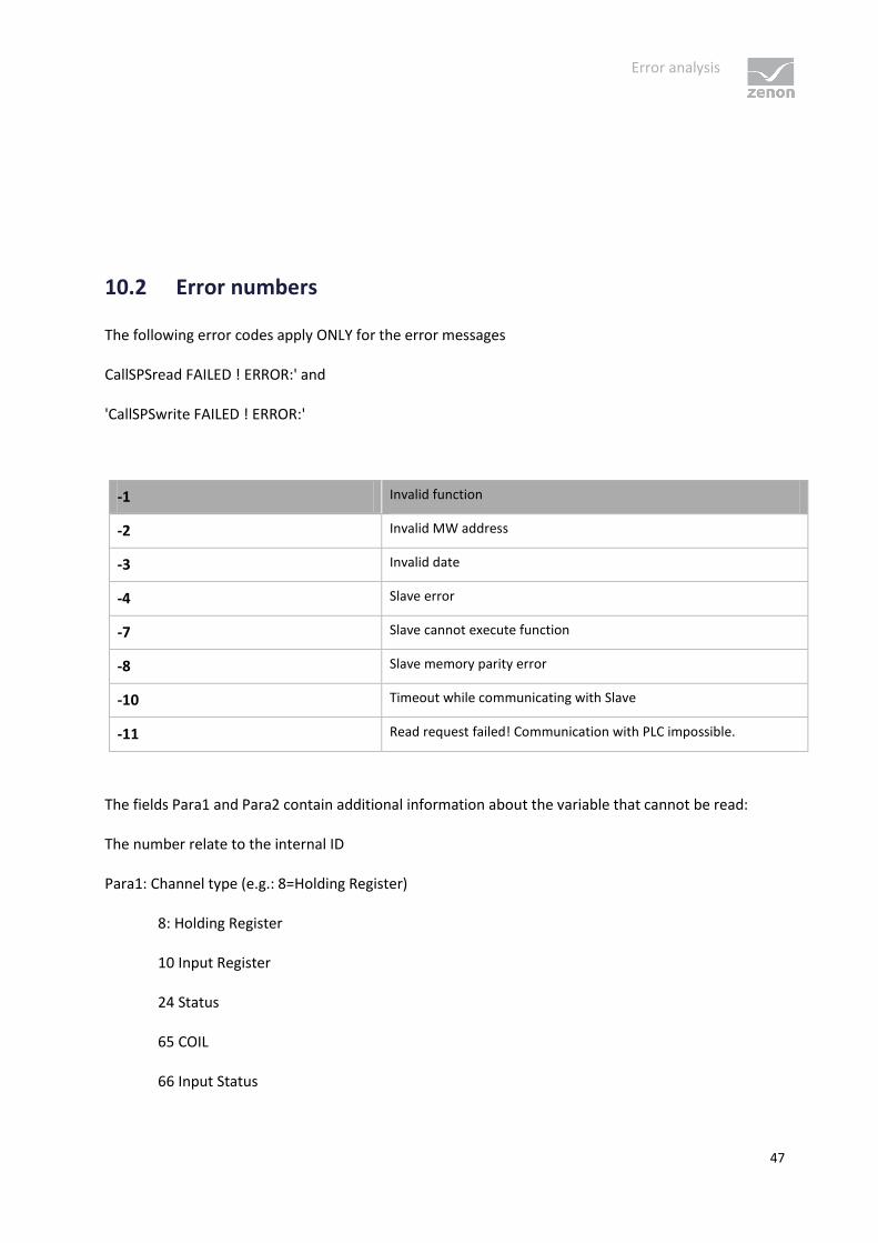
10.2 Error numbers
The following error codes apply ONLY for the error messages
CallSPSread FAILED ! ERROR:' and
'CallSPSwrite FAILED ! ERROR:'
-1 Invalid function
-2 Invalid MW address
-3 Invalid date
-4 Slave error
-7 Slave cannot execute function
-8 Slave memory parity error
-10 Timeout while communicating with Slave
-11 Read request failed! Communication with PLC impossible.
The fields Para1 and Para2 contain additional information about the variable that cannot be read:
The number relate to the internal ID
Para1: Channel type (e.g.: 8=Holding Register)
8: Holding Register
10 Input Register
24 Status
65 COIL
66 Input Status

Error analysis
48
67 Preset Single Register
Para2: Data type (e.g: 2= Word, UINT)
1: INT
2: UINT
3: DINT
4: UDINT
5: REAL
8: BOOL
9: SINT
10: USINT
10.3 Check list
Is the COM port in use by another application or are the settings incorrect?
Is the device (PLC) that you are trying to communicate with connected to the power supply?
Is the cable between PLC and PC/IPC connected correctly?
Do the used addresses exist in the PLC ?
Was the log file analyzed with the help of the Diagnosis Viewer? (Which errors occurred)?
When using communication via TCP: make sure the configured port is free and not blocked by a
firewall.
Test with telnet: can you establish a connection?