Embed Size (px)
Citation preview
Modicon M580 Standalone
HRB62666 12/2015
HR
B62
666.
04
www.schneider-electric.com
Modicon M580 StandaloneSystem Planning Guide forFrequently Used Architectures
12/2015

The information provided in this documentation contains general descriptions and/or technical characteristics of the performance of the products contained herein. This documentation is not intended as a substitute for and is not to be used for determining suitability or reliability of these products for specific user applications. It is the duty of any such user or integrator to perform the appropriate and complete risk analysis, evaluation and testing of the products with respect to the relevant specific application or use thereof. Neither Schneider Electric nor any of its affiliates or subsidiaries shall be responsible or liable for misuse of the information contained herein. If you have any suggestions for improvements or amendments or have found errors in this publication, please notify us.
No part of this document may be reproduced in any form or by any means, electronic or mechanical, including photocopying, without express written permission of Schneider Electric.
All pertinent state, regional, and local safety regulations must be observed when installing and using this product. For reasons of safety and to help ensure compliance with documented system data, only the manufacturer should perform repairs to components.
When devices are used for applications with technical safety requirements, the relevant instructions must be followed.
Failure to use Schneider Electric software or approved software with our hardware products may result in injury, harm, or improper operating results.
Failure to observe this information can result in injury or equipment damage.
© 2015 Schneider Electric. All rights reserved.
2 HRB62666 12/2015
Table of Contents
Safety Information . . . . . . . . . . . . . . . . . . . . . . . . . . . . . 5About the Book. . . . . . . . . . . . . . . . . . . . . . . . . . . . . . . . 9
Part I Modicon M580 System Introduction . . . . . . . . . . . 13Chapter 1 Modicon M580 System. . . . . . . . . . . . . . . . . . . . . . . . . . 15
Modicon M580 Typical System Introduction . . . . . . . . . . . . . . . . . . . . 16Modicon M580 Typical System Components . . . . . . . . . . . . . . . . . . . 20Typical Modicon M580 RIO/DIO Network Topologies . . . . . . . . . . . . . 29Modicon M580 DIO Connections. . . . . . . . . . . . . . . . . . . . . . . . . . . . . 32Modicon M580 System Features. . . . . . . . . . . . . . . . . . . . . . . . . . . . . 33
Chapter 2 Modules in an M580 System . . . . . . . . . . . . . . . . . . . . . 35Modules and Switches in an M580 System. . . . . . . . . . . . . . . . . . . . . 36Modicon X80 I/O Modules . . . . . . . . . . . . . . . . . . . . . . . . . . . . . . . . . . 40Distributed Equipment . . . . . . . . . . . . . . . . . . . . . . . . . . . . . . . . . . . . . 48
Part II Planning and Designing a Typical M580 Network 49Chapter 3 Selecting the Correct Topology . . . . . . . . . . . . . . . . . . 51
Project Life Cycle. . . . . . . . . . . . . . . . . . . . . . . . . . . . . . . . . . . . . . . . . 53Planning the Appropriate Network Topology . . . . . . . . . . . . . . . . . . . . 54Selecting a CPU for your M580 System . . . . . . . . . . . . . . . . . . . . . . . 59Planning an Isolated DIO Network . . . . . . . . . . . . . . . . . . . . . . . . . . . 62Adding an Independent DIO Network . . . . . . . . . . . . . . . . . . . . . . . . . 63Planning a Simple Daisy Chain Loop . . . . . . . . . . . . . . . . . . . . . . . . . 65Local Rack Communication Module Installation . . . . . . . . . . . . . . . . . 67Using Premium Racks in an M580 System . . . . . . . . . . . . . . . . . . . . . 69Using Fiber Converter Modules. . . . . . . . . . . . . . . . . . . . . . . . . . . . . . 75
Chapter 4 Performance . . . . . . . . . . . . . . . . . . . . . . . . . . . . . . . . . . 794.1 System Performance . . . . . . . . . . . . . . . . . . . . . . . . . . . . . . . . . . . . . . 80
System Performance . . . . . . . . . . . . . . . . . . . . . . . . . . . . . . . . . . . . . . 81System Throughput Considerations . . . . . . . . . . . . . . . . . . . . . . . . . . 82Calculating the Minimum MAST Cycle Time . . . . . . . . . . . . . . . . . . . . 84
4.2 Application Response Time. . . . . . . . . . . . . . . . . . . . . . . . . . . . . . . . . 85Simplified Presentation of Application Response Time . . . . . . . . . . . . 86Application Response Time. . . . . . . . . . . . . . . . . . . . . . . . . . . . . . . . . 89Application Response Time Examples . . . . . . . . . . . . . . . . . . . . . . . . 92Optimizing Application Response Time. . . . . . . . . . . . . . . . . . . . . . . . 94
HRB62666 12/2015 3
4.3 Communication Loss Detection Times. . . . . . . . . . . . . . . . . . . . . . . . . 96Communication Loss Detection Times. . . . . . . . . . . . . . . . . . . . . . . . . 96
Part III M580 System Commissioning and Diagnostics . 99Chapter 5 Commissioning . . . . . . . . . . . . . . . . . . . . . . . . . . . . . . . 101
Setting the Location of the Ethernet RIO Drop. . . . . . . . . . . . . . . . . . . 102Powering Up Modules Without a Downloaded Application . . . . . . . . . 103Downloading CPU Applications . . . . . . . . . . . . . . . . . . . . . . . . . . . . . . 104Establishing Transparency between a USB and Device Network . . . . 106Initial Start After Application Download . . . . . . . . . . . . . . . . . . . . . . . . 107Powering Down/Powering Up Modules . . . . . . . . . . . . . . . . . . . . . . . . 108Starting and Stopping an Application . . . . . . . . . . . . . . . . . . . . . . . . . . 109
Chapter 6 System Diagnostics . . . . . . . . . . . . . . . . . . . . . . . . . . . . 111System Diagnostics . . . . . . . . . . . . . . . . . . . . . . . . . . . . . . . . . . . . . . . 112Main Ring Diagnostics . . . . . . . . . . . . . . . . . . . . . . . . . . . . . . . . . . . . . 116
Appendices . . . . . . . . . . . . . . . . . . . . . . . . . . . . . . . . . . . . . . . . . 117Appendix A Frequently Asked Questions (FAQ) . . . . . . . . . . . . . . . 119
Frequently Asked Questions (FAQ) . . . . . . . . . . . . . . . . . . . . . . . . . . . 119Appendix B Detected Error Codes . . . . . . . . . . . . . . . . . . . . . . . . . . 127
EtherNet/IP Implicit or Explicit Messaging Detected Error Codes . . . . 128Explicit Messaging: Communication and Operation Reports . . . . . . . . 131
Appendix C Design Principles of M580 Networks . . . . . . . . . . . . . . 135C.1 Network Determinism Parameters . . . . . . . . . . . . . . . . . . . . . . . . . . . . 136
Network Determinism Parameters . . . . . . . . . . . . . . . . . . . . . . . . . . . . 136C.2 RIO Network Design Principles . . . . . . . . . . . . . . . . . . . . . . . . . . . . . . 137
RIO Network Design Principles . . . . . . . . . . . . . . . . . . . . . . . . . . . . . . 138Defined Architecture: Topologies . . . . . . . . . . . . . . . . . . . . . . . . . . . . . 139Defined Architecture: Junctions . . . . . . . . . . . . . . . . . . . . . . . . . . . . . . 140
C.3 RIO with DIO Network Design Principles . . . . . . . . . . . . . . . . . . . . . . . 141RIO with DIO Network Design Principles . . . . . . . . . . . . . . . . . . . . . . . 142Defined Architecture: Topologies . . . . . . . . . . . . . . . . . . . . . . . . . . . . . 143RIO and DIO Defined Architecture: Junctions . . . . . . . . . . . . . . . . . . . 145
Glossary . . . . . . . . . . . . . . . . . . . . . . . . . . . . . . . . . . . . . . . . . 147Index . . . . . . . . . . . . . . . . . . . . . . . . . . . . . . . . . . . . . . . . . 165
4 HRB62666 12/2015
Safety Information
Important Information
NOTICE
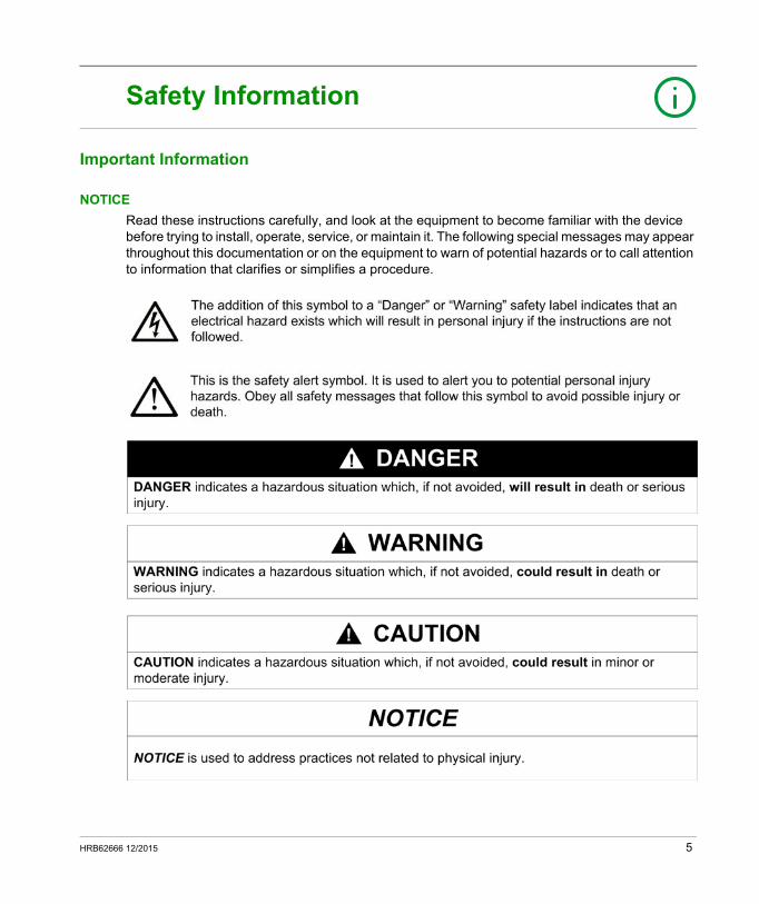
Read these instructions carefully, and look at the equipment to become familiar with the device before trying to install, operate, service, or maintain it. The following special messages may appear throughout this documentation or on the equipment to warn of potential hazards or to call attention to information that clarifies or simplifies a procedure.
HRB62666 12/2015 5
PLEASE NOTE
Electrical equipment should be installed, operated, serviced, and maintained only by qualified personnel. No responsibility is assumed by Schneider Electric for any consequences arising out of the use of this material.
A qualified person is one who has skills and knowledge related to the construction and operation of electrical equipment and its installation, and has received safety training to recognize and avoid the hazards involved.
BEFORE YOU BEGIN
Do not use this product on machinery lacking effective point-of-operation guarding. Lack of effective point-of-operation guarding on a machine can result in serious injury to the operator of that machine.
This automation equipment and related software is used to control a variety of industrial processes. The type or model of automation equipment suitable for each application will vary depending on factors such as the control function required, degree of protection required, production methods, unusual conditions, government regulations, etc. In some applications, more than one processor may be required, as when backup redundancy is needed.
Only you, the user, machine builder or system integrator can be aware of all the conditions and factors present during setup, operation, and maintenance of the machine and, therefore, can determine the automation equipment and the related safeties and interlocks which can be properly used. When selecting automation and control equipment and related software for a particular application, you should refer to the applicable local and national standards and regulations. The National Safety Council's Accident Prevention Manual (nationally recognized in the United States of America) also provides much useful information.
In some applications, such as packaging machinery, additional operator protection such as point-of-operation guarding must be provided. This is necessary if the operator's hands and other parts of the body are free to enter the pinch points or other hazardous areas and serious injury can occur. Software products alone cannot protect an operator from injury. For this reason the software cannot be substituted for or take the place of point-of-operation protection.
WARNINGUNGUARDED EQUIPMENT
Do not use this software and related automation equipment on equipment which does not have point-of-operation protection.
Do not reach into machinery during operation.
Failure to follow these instructions can result in death, serious injury, or equipment damage.
6 HRB62666 12/2015
Ensure that appropriate safeties and mechanical/electrical interlocks related to point-of-operation protection have been installed and are operational before placing the equipment into service. All interlocks and safeties related to point-of-operation protection must be coordinated with the related automation equipment and software programming.
NOTE: Coordination of safeties and mechanical/electrical interlocks for point-of-operation protection is outside the scope of the Function Block Library, System User Guide, or other implementation referenced in this documentation.
START-UP AND TEST
Before using electrical control and automation equipment for regular operation after installation, the system should be given a start-up test by qualified personnel to verify correct operation of the equipment. It is important that arrangements for such a check be made and that enough time is allowed to perform complete and satisfactory testing.
Follow all start-up tests recommended in the equipment documentation. Store all equipment documentation for future references.
Software testing must be done in both simulated and real environments.
Verify that the completed system is free from all short circuits and temporary grounds that are not installed according to local regulations (according to the National Electrical Code in the U.S.A, for instance). If high-potential voltage testing is necessary, follow recommendations in equipment documentation to prevent accidental equipment damage.
Before energizing equipment: Remove tools, meters, and debris from equipment. Close the equipment enclosure door. Remove all temporary grounds from incoming power lines. Perform all start-up tests recommended by the manufacturer.
CAUTIONEQUIPMENT OPERATION HAZARD
Verify that all installation and set up procedures have been completed. Before operational tests are performed, remove all blocks or other temporary holding means
used for shipment from all component devices. Remove tools, meters, and debris from equipment.
Failure to follow these instructions can result in injury or equipment damage.
HRB62666 12/2015 7

OPERATION AND ADJUSTMENTS
The following precautions are from the NEMA Standards Publication ICS 7.1-1995 (English version prevails): Regardless of the care exercised in the design and manufacture of equipment or in the selection
and ratings of components, there are hazards that can be encountered if such equipment is improperly operated.
It is sometimes possible to misadjust the equipment and thus produce unsatisfactory or unsafe operation. Always use the manufacturer’s instructions as a guide for functional adjustments. Personnel who have access to these adjustments should be familiar with the equipment manufacturer’s instructions and the machinery used with the electrical equipment.
Only those operational adjustments actually required by the operator should be accessible to the operator. Access to other controls should be restricted to prevent unauthorized changes in operating characteristics.
8 HRB62666 12/2015
About the Book
At a Glance
Document Scope
PlantStruxure is a Schneider Electric program designed to address the key challenges of many different types of users, including plant managers, operations managers, engineers, maintenance teams, and operators, by delivering a system that is scalable, flexible, integrated, and collaborative.
This document presents one of the PlantStruxure features, using Ethernet as the backbone around the Modicon M580 offer and connecting an M580 local rack and M580 RIO drops.
This guide provides detailed information about planning frequently used M580 architectures, including the following: Ethernet I/O networks (RIO and distributed equipment integrated on the same physical network) topology rules and recommendations for choosing a network configuration role of network option switch modules system commissioning and maintenance system performance and limitations system diagnostics
NOTE: The specific configuration settings contained in this guide are intended to be used for instructional purposes only. The settings required for your specific configuration may differ from the examples presented in this guide.
Validity Note
This document is valid for the M580 system when used with Unity Pro 11.0 or later.
The technical characteristics of the devices described in this document also appear online. To access this information online:
Step Action
1 Go to the Schneider Electric home page www.schneider-electric.com.
2 In the Search box type the reference of a product or the name of a product range. Do not include blank spaces in the reference or product range. To get information on grouping similar modules, use asterisks (*).
3 If you entered a reference, go to the Product Datasheets search results and click on the reference that interests you.If you entered the name of a product range, go to the Product Ranges search results and click on the product range that interests you.
4 If more than one reference appears in the Products search results, click on the reference that interests you.
HRB62666 12/2015 9
The characteristics that are presented in this manual should be the same as those characteristics that appear online. In line with our policy of constant improvement, we may revise content over time to improve clarity and accuracy. If you see a difference between the manual and online information, use the online information as your reference.
Related Documents
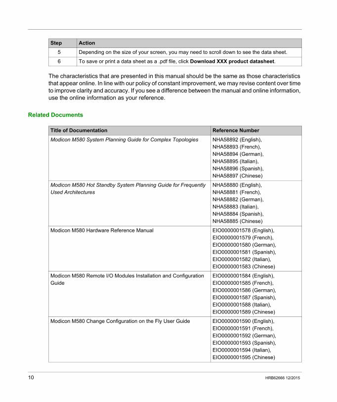
5 Depending on the size of your screen, you may need to scroll down to see the data sheet.
6 To save or print a data sheet as a .pdf file, click Download XXX product datasheet.
Step Action
Title of Documentation Reference Number
Modicon M580 System Planning Guide for Complex Topologies NHA58892 (English), NHA58893 (French), NHA58894 (German), NHA58895 (Italian), NHA58896 (Spanish), NHA58897 (Chinese)
Modicon M580 Hot Standby System Planning Guide for Frequently Used Architectures
NHA58880 (English), NHA58881 (French), NHA58882 (German), NHA58883 (Italian), NHA58884 (Spanish), NHA58885 (Chinese)
Modicon M580 Hardware Reference Manual EIO0000001578 (English), EIO0000001579 (French), EIO0000001580 (German), EIO0000001581 (Spanish), EIO0000001582 (Italian), EIO0000001583 (Chinese)
Modicon M580 Remote I/O Modules Installation and Configuration Guide
EIO0000001584 (English), EIO0000001585 (French), EIO0000001586 (German), EIO0000001587 (Spanish), EIO0000001588 (Italian), EIO0000001589 (Chinese)
Modicon M580 Change Configuration on the Fly User Guide EIO0000001590 (English), EIO0000001591 (French), EIO0000001592 (German), EIO0000001593 (Spanish), EIO0000001594 (Italian), EIO0000001595 (Chinese)
10 HRB62666 12/2015
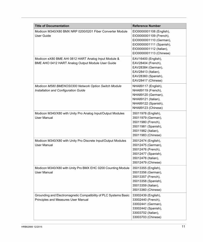
Modicon M340/X80 BMX NRP 0200/0201 Fiber Converter Module User Guide
EIO0000001108 (English), EIO0000001109 (French), EIO0000001110 (German), EIO0000001111 (Spanish), EIO0000001112 (Italian), EIO0000001113 (Chinese)
Modicon eX80 BME AHI 0812 HART Analog Input Module & BME AHO 0412 HART Analog Output Module User Guide
EAV16400 (English), EAV28404 (French), EAV28384 (German), EAV28413 (Italian), EAV28360 (Spanish), EAV28417 (Chinese)
Modicon M580 BMENOS0300 Network Option Switch Module Installation and Configuration Guide
NHA89117 (English),NHA89119 (French),NHA89120 (German),NHA89121 (Italian),NHA89122 (Spanish),NHA89123 (Chinese)
Modicon M340/X80 with Unity Pro Analog Input/Output Modules User Manual
35011978 (English), 35011979 (German), 35011980 (French),35011981 (Spanish), 35011982 (Italian), 35011983 (Chinese)
Modicon M340/X80 with Unity Pro Discrete Input/Output Modules User Manual
35012474 (English),35012475 (German), 35012476 (French), 35012477 (Spanish), 35012478 (Italian), 35012479 (Chinese)
Modicon M340/X80 with Unity Pro BMX EHC 0200 Counting Module User Manual
35013355 (English), 35013356 (German), 35013357 (French), 35013358 (Spanish), 35013359 (Italian), 35013360 (Chinese)
Grounding and Electromagnetic Compatibility of PLC Systems Basic Principles and Measures User Manual
33002439 (English), 33002440 (French), 33002441 (German), 33002442 (Spanish), 33003702 (Italian), 33003703 (Chinese)
Title of Documentation Reference Number
HRB62666 12/2015 11
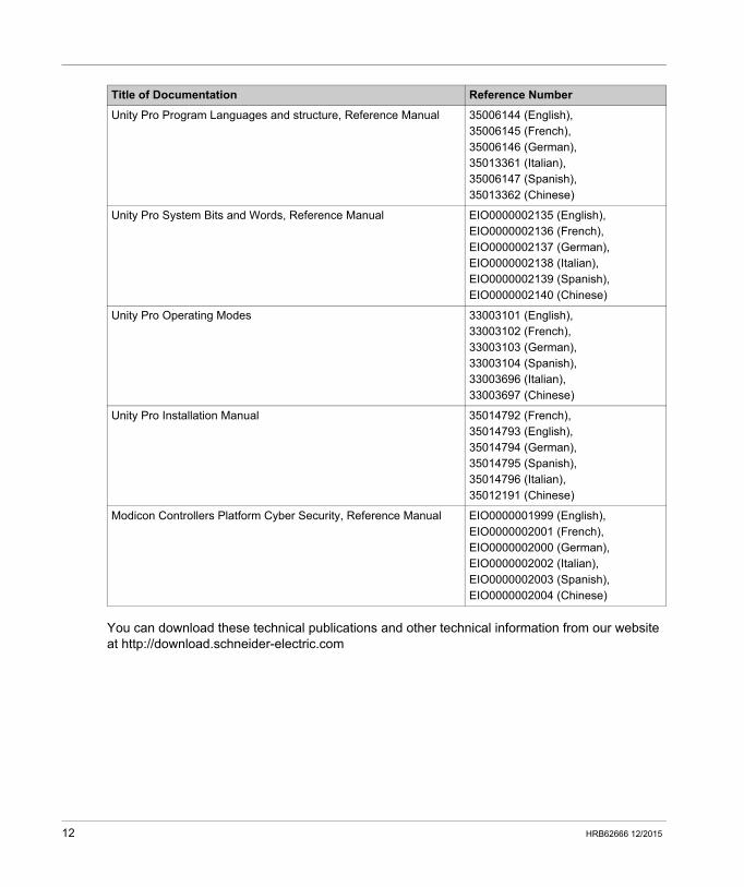
You can download these technical publications and other technical information from our website at http://download.schneider-electric.com
Unity Pro Program Languages and structure, Reference Manual 35006144 (English), 35006145 (French), 35006146 (German), 35013361 (Italian), 35006147 (Spanish), 35013362 (Chinese)
Unity Pro System Bits and Words, Reference Manual EIO0000002135 (English), EIO0000002136 (French), EIO0000002137 (German), EIO0000002138 (Italian), EIO0000002139 (Spanish), EIO0000002140 (Chinese)
Unity Pro Operating Modes 33003101 (English), 33003102 (French), 33003103 (German), 33003104 (Spanish), 33003696 (Italian), 33003697 (Chinese)
Unity Pro Installation Manual 35014792 (French), 35014793 (English), 35014794 (German), 35014795 (Spanish), 35014796 (Italian), 35012191 (Chinese)
Modicon Controllers Platform Cyber Security, Reference Manual EIO0000001999 (English), EIO0000002001 (French), EIO0000002000 (German), EIO0000002002 (Italian), EIO0000002003 (Spanish), EIO0000002004 (Chinese)
Title of Documentation Reference Number
12 HRB62666 12/2015
Modicon M580 Standalone
Modicon M580 System Introduction
HRB62666 12/2015
Modicon M580 System Introduction
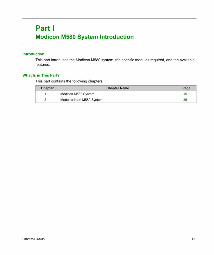
Part IModicon M580 System Introduction
Introduction
This part introduces the Modicon M580 system, the specific modules required, and the available features.
What Is in This Part?
This part contains the following chapters:
Chapter Chapter Name Page
1 Modicon M580 System 15
2 Modules in an M580 System 35
HRB62666 12/2015 13

Modicon M580 System Introduction
14 HRB62666 12/2015
Modicon M580 Standalone
Modicon M580 System
HRB62666 12/2015
Modicon M580 System
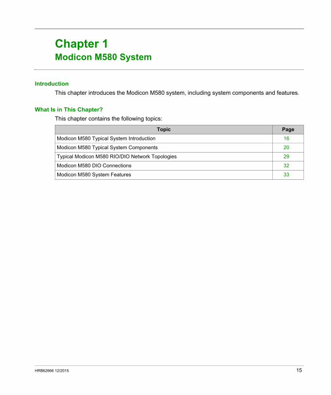
Chapter 1Modicon M580 System
Introduction
This chapter introduces the Modicon M580 system, including system components and features.
What Is in This Chapter?
This chapter contains the following topics:
Topic Page
Modicon M580 Typical System Introduction 16
Modicon M580 Typical System Components 20
Typical Modicon M580 RIO/DIO Network Topologies 29
Modicon M580 DIO Connections 32
Modicon M580 System Features 33
HRB62666 12/2015 15
Modicon M580 System
Modicon M580 Typical System Introduction
Introduction
A typical Modicon M580 system is designed and tested for simultaneous use of: a main local rack (see page 20) and the ability to extend to other local racks RIO drops (see page 22) that support Ethernet and X Bus communications across the
backplane Ethernet distributed equipment (see page 25) network option switch modules (see page 23) RIO and distributed equipment integrated on the same physical network RIO and DIO sub-rings that communicate with the RIO main ring third-party modules and devices daisy-chain ring architectures provided by communication modules with dual Ethernet ports
An M580 system provides automatic network recovery of less than 50 ms and deterministic RIO performance.
An M580 system uses Modicon X80 I/O modules, many of which are used in an M340 system. The system also supports several Ethernet-based eX80 I/O modules, which can be installed on both the main local rack and main remote racks. M580 also supports Premium I/O modules installed on an extended local rack.
NOTE: To use a dual-ring switch (DRS) to connect distributed equipment to the M580 network, refer to the M580 System Planning Guide for Complex Topologies (see page 9).
16 HRB62666 12/2015
Modicon M580 System
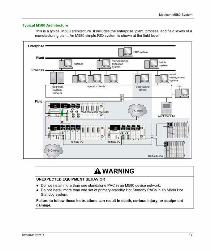
Typical M580 Architecture
This is a typical M580 architecture. It includes the enterprise, plant, process, and field levels of a manufacturing plant. An M580 simple RIO system is shown at the field level:
WARNINGUNEXPECTED EQUIPMENT BEHAVIOR
Do not install more than one standalone PAC in an M580 device network. Do not install more than one set of primary-standby Hot Standby PACs in an M580 Hot
Standby system.
Failure to follow these instructions can result in death, serious injury, or equipment damage.
HRB62666 12/2015 17
Modicon M580 System
M580 Life Cycle
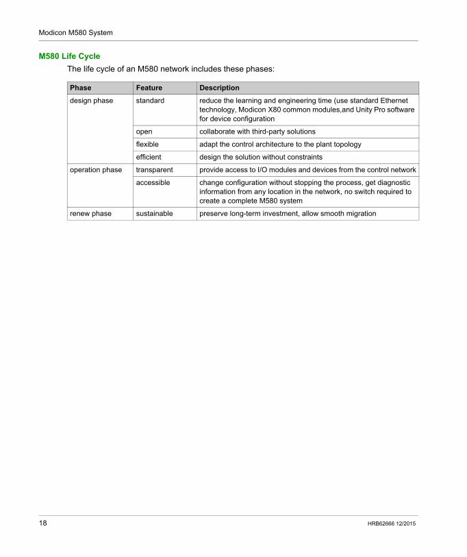
The life cycle of an M580 network includes these phases:
Phase Feature Description
design phase standard reduce the learning and engineering time (use standard Ethernet technology, Modicon X80 common modules,and Unity Pro software for device configuration
open collaborate with third-party solutions
flexible adapt the control architecture to the plant topology
efficient design the solution without constraints
operation phase transparent provide access to I/O modules and devices from the control network
accessible change configuration without stopping the process, get diagnostic information from any location in the network, no switch required to create a complete M580 system
renew phase sustainable preserve long-term investment, allow smooth migration
18 HRB62666 12/2015
Modicon M580 System
M580 Simple RIO Example
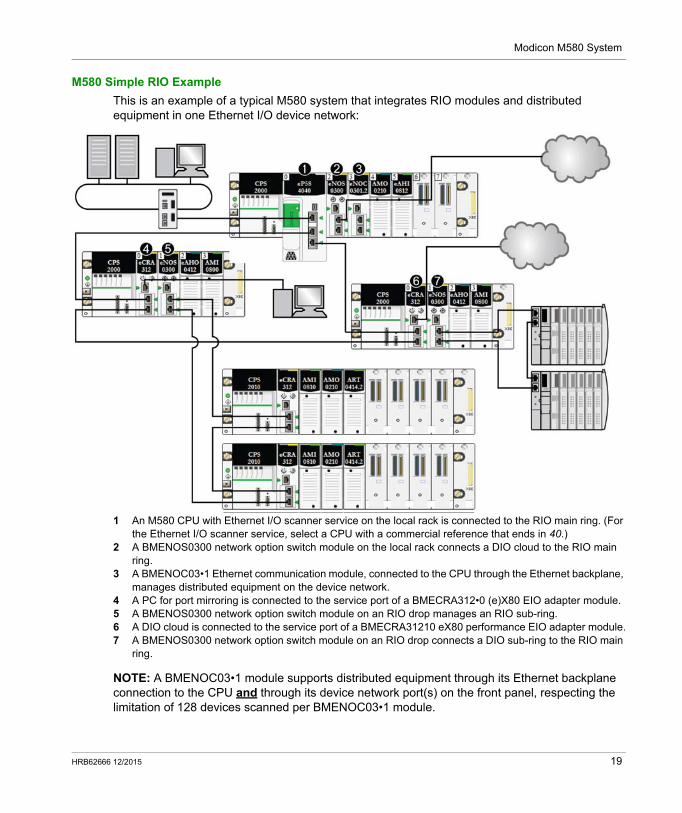
This is an example of a typical M580 system that integrates RIO modules and distributed equipment in one Ethernet I/O device network:
1 An M580 CPU with Ethernet I/O scanner service on the local rack is connected to the RIO main ring. (For the Ethernet I/O scanner service, select a CPU with a commercial reference that ends in 40.)
2 A BMENOS0300 network option switch module on the local rack connects a DIO cloud to the RIO main ring.
3 A BMENOC03•1 Ethernet communication module, connected to the CPU through the Ethernet backplane, manages distributed equipment on the device network.
4 A PC for port mirroring is connected to the service port of a BMECRA312•0 (e)X80 EIO adapter module.5 A BMENOS0300 network option switch module on an RIO drop manages an RIO sub-ring.6 A DIO cloud is connected to the service port of a BMECRA31210 eX80 performance EIO adapter module.7 A BMENOS0300 network option switch module on an RIO drop connects a DIO sub-ring to the RIO main
ring.
NOTE: A BMENOC03•1 module supports distributed equipment through its Ethernet backplane connection to the CPU and through its device network port(s) on the front panel, respecting the limitation of 128 devices scanned per BMENOC03•1 module.
HRB62666 12/2015 19
Modicon M580 System
Modicon M580 Typical System Components
Introduction
When you connect the M580 local rack to one or more RIO drops in an M580 system, you establish the RIO main ring.
These are the available physical components for an RIO main ring: local rack: An M580 local rack contains the CPU and a power supply. The local rack consists of
a main rack and sometimes an (optional) extended rack. RIO drops: RIO drops are M580 racks that include I/O modules that are connected to an
Ethernet RIO network. The The drops are managed by and Ethernet RIO adapter module. A drop can be a single rack or a main rack plus an (optional) extended rack.
BMENOS0300 network option switch modules.
NOTE: Be aware that some M580 CPU models do not support RIO scanning. CPUs with commercial references ending in 20 support only local I/O and distributed equipment (DIO scanning). CPUs with commercial references ending in 40 support RIO scanning as well as local I/O modules and distributed equipment. (M580 Hot Standby CPUs (see Modicon M580 Hot Standby, System Planning Guide for, Frequently Used Architectures) that end in 40 do not support local I/O modules.)Connect distributed equipment to the M580 network with these devices: dual-ring switch (DRS) service port of the CPU BMENOC03•1 Ethernet communication module BMENOS0300 network option switch module
Refer to the M580 System Planning Guide for Complex Topologies (see Modicon M580, System Planning Guide for, Complex Topologies).
Local Rack
Within the main ring in a typical M580 system, a local rack contains the CPU, a power supply, and a maximum of six BMENOC03•1 Ethernet communication modules or other communication modules (depending upon the CPU you choose (see page 59)), and appropriate expert and/or I/O modules.
A local rack consists of one main rack and up to seven full extended racks (up to 14 Premium half racks (see page 71)), depending on the CPU you use. The main rack is required in the M580 architecture; extended racks are optional, and when present, are considered part of the local rack.
20 HRB62666 12/2015
Modicon M580 System
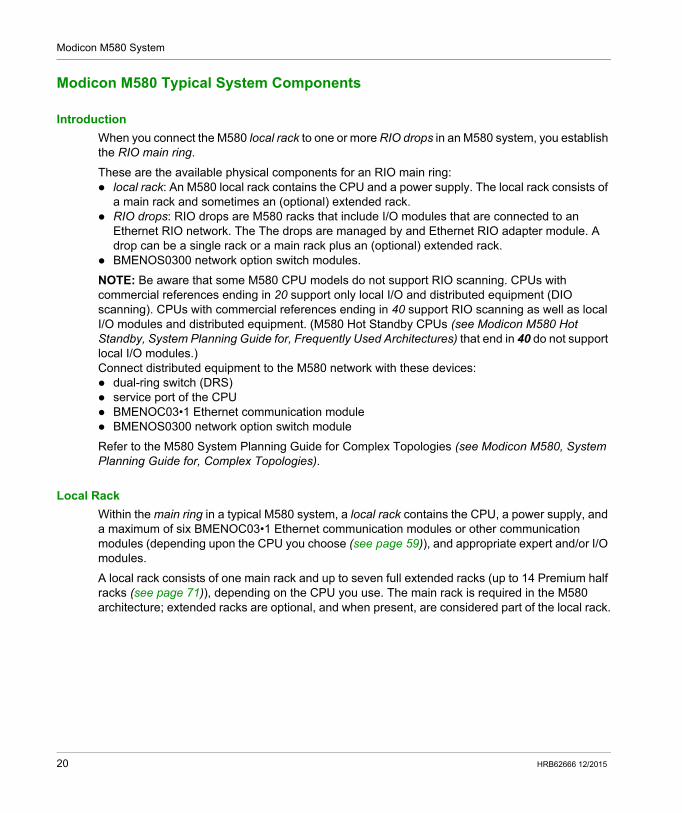
This graphic shows an M580 main local rack with an extended local rack:
The main local rack can be installed on a BME XBP ••00 Ethernet backplane or a BMX XBP ••00 X Bus backplane (PV:02 or later).
The extended local racks are either BMX XBP ••00 X Bus backplanes or, for Premium I/O, TSX RKY •EX backplanes.
Module/backplane compatibility: You can install Modicon X80 I/O modules on BME XBP ••00 Ethernet or BMX XBP 0•00 X Bus
backplanes. You can install Modicon eX80 (example: PME SWT 0100 and BME AH• 0•12 modules) on
BME XBP ••00 Ethernet backplanes only. You can install Modicon eX80 and Modicon X80 modules on BME XBP ••02 backplanes, which
support both Ethernet and X Bus communications. You can install Premium I/O modules on TSX RKY •EX Premium backplanes only.
Backplane compatibility:
Local Racks Remote Racks
Main Rack Extended Rack Main Rack Extended Rack
BMEXBP••00 Ethernet X — X —
BMXXBP0•00 X Bus X1 X X2 X
TSXRKY•EX Premium — X — —
BMEXBP0602(H) Ethernet/X Bus
X — X —
BMEXBP1002(H) Ethernet/X Bus
X — X —
X: allowed—: not allowed1 Requires a hardware revision of PV:02 or later.2 Requires a hardware revision PV:02 or later f you use a BMECRA31210 eX80 performance EIO adapter module.
HRB62666 12/2015 21
Modicon M580 System
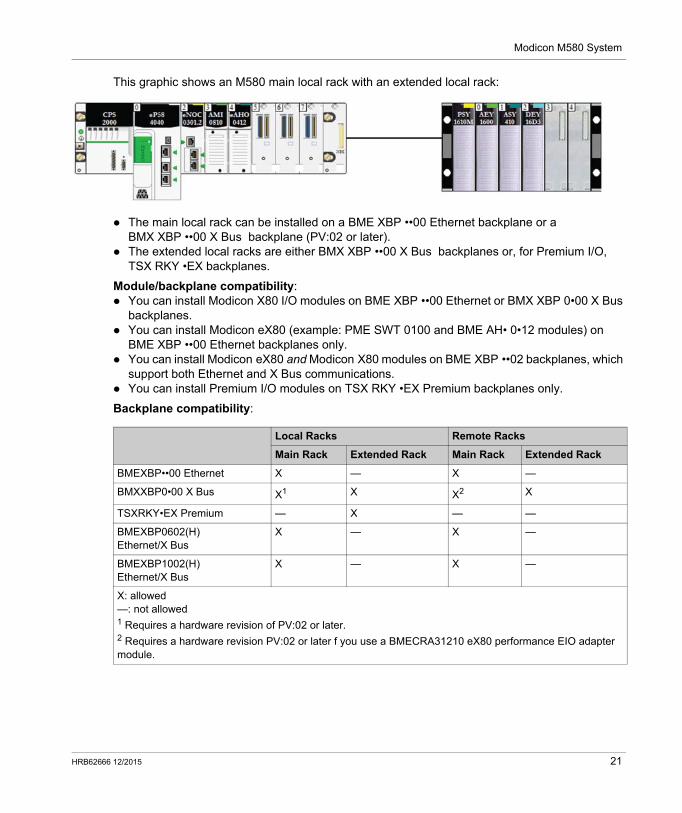
BME XBP ••0• backplanes also provide X Bus connections across the backplane, and are therefore compatible with Modicon X80 modules supported by the M580 system. BMXXPB••00 X Bus backplanes, on the other hand, do not have the connections required to support eX80 modules.
1 Ethernet connector2 X Bus connector
NOTE: Ethernet racks are also described in further detail in the Modicon M580 Hardware Reference Manual.
RIO Drops
An RIO drop is connected to an RIO ring. These drops consist of one or two racks of (e)X80 I/O modules and/or third-party modules. An RIO drop is connected to the daisy-chain ring on which the Ethernet RIO network resides. Each remote drop contains one BM•CRA312•0 (e)X80 EIO adapter module. Each rack in a remote drop contains its own power supply module.
NOTE: You can also install Quantum RIO (see Quantum EIO, System Planning Guide) drops in an M580 RIO main ring. Refer to the Quantum Ethernet I/O System Planning Guide for details.
RIO drops provide deterministic communication on the main ring and the RIO sub-rings so that RIO modules synchronize with CPU tasks (MAST, FAST, AUX0, AUX1); whereas distributed equipment is not deterministic.
Remote eX80 EIO adapter modules are available as Ethernet (BME) and X Bus (BMX) communicators. If you plan to use X80 I/O modules that require Ethernet, then choose a BME-style X80 EIO adapter module. If your X80 I/O uses only X Bus for backplane communication, then you can use a BMX-style X80 EIO adapter module or a BME-style X80 EIO adapter module.
RIO drops are connected to the main ring via copper cable to the CPU with Ethernet I/O scanner service (see page 59) on the local rack or to another RIO drop (which may be connected to another RIO drop or the CPU).
An RIO drop contains a main remote rack and an optional extended remote rack, depending on the (e)X80 EIO adapter module that is on the RIO drop: If you install a BM•CRA31200 (e)X80 standard EIO adapter module, extended remote racks are
not supported. If you install a BM•CRA31210 (e)X80 performance EIO adapter module, one extended remote
rack is supported.
22 HRB62666 12/2015
Modicon M580 System
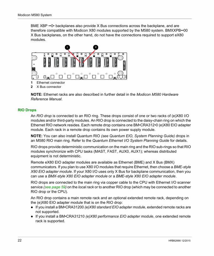
The adapter module is installed in slot 0 (directly to the right of the power supply) in the main rack of the drop.
A maximum of 31 RIO drops can be supported in an M580 network.
This graphic shows an RIO drop (with a remote extended rack) connected to a local rack (with a local extended rack):
1 local main rack2 local extended rack3 remote main rack4 remote extended rack
Network Option Switch Modules
A BMENOS0300 network option switch module in an M580 network can connect RIO and DIO sub-rings as well as DIO clouds to the RIO main ring. A network option switch module is considered a communication module when you calculate the maximum number of communication modules allowed on a local rack.
Use a BMENOS0300 module for these purposes: Reduce system costs by using a BMENOS0300 module instead of a dual-ring switch (DRS) to
connect RIO and DIO sub-rings to the Ethernet I/O network and instead of a BMENOC03•1 to connect distributed equipment to the network.
Enable RSTP recovery support for devices and cables on RIO and DIO sub-rings. Isolate the RIO and DIO sub-rings from one another and from the main ring to improve system
robustness.
HRB62666 12/2015 23
Modicon M580 System
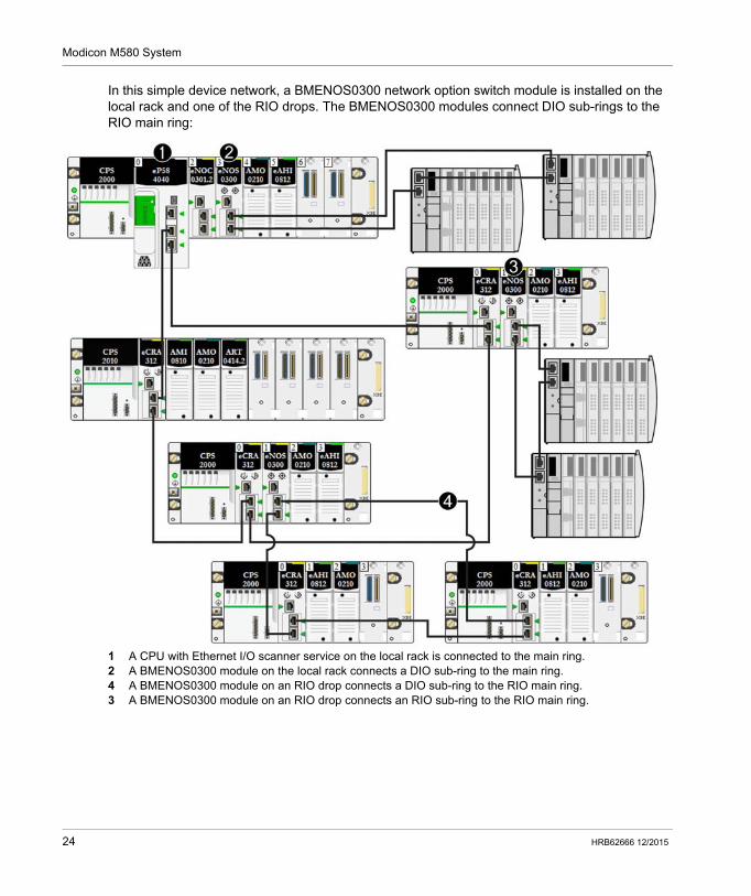
In this simple device network, a BMENOS0300 network option switch module is installed on the local rack and one of the RIO drops. The BMENOS0300 modules connect DIO sub-rings to the RIO main ring:
1 A CPU with Ethernet I/O scanner service on the local rack is connected to the main ring.2 A BMENOS0300 module on the local rack connects a DIO sub-ring to the main ring.4 A BMENOS0300 module on an RIO drop connects a DIO sub-ring to the RIO main ring.3 A BMENOS0300 module on an RIO drop connects an RIO sub-ring to the RIO main ring.
24 HRB62666 12/2015
Modicon M580 System
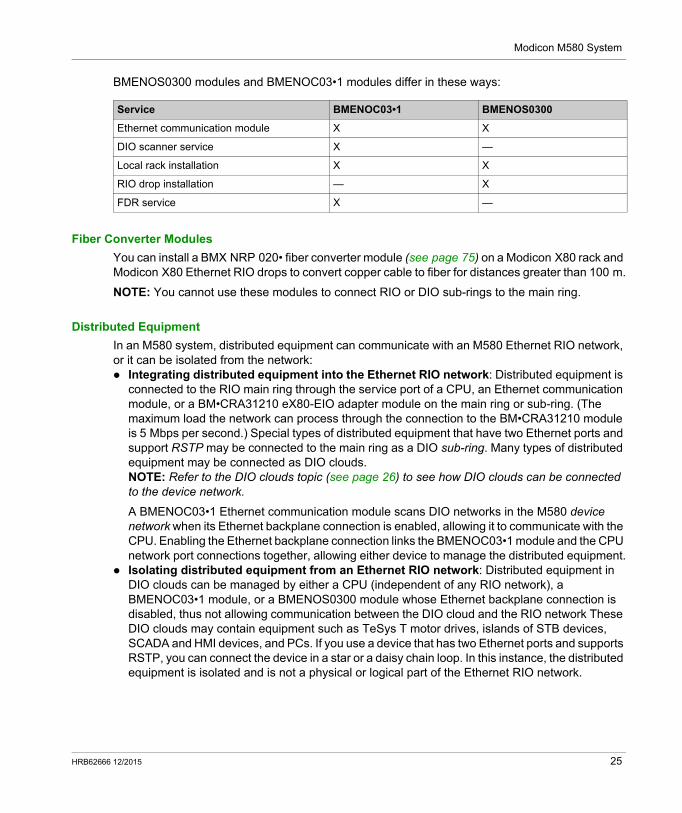
BMENOS0300 modules and BMENOC03•1 modules differ in these ways:
Fiber Converter Modules
You can install a BMX NRP 020• fiber converter module (see page 75) on a Modicon X80 rack and Modicon X80 Ethernet RIO drops to convert copper cable to fiber for distances greater than 100 m.
NOTE: You cannot use these modules to connect RIO or DIO sub-rings to the main ring.
Distributed Equipment
In an M580 system, distributed equipment can communicate with an M580 Ethernet RIO network, or it can be isolated from the network: Integrating distributed equipment into the Ethernet RIO network: Distributed equipment is
connected to the RIO main ring through the service port of a CPU, an Ethernet communication module, or a BM•CRA31210 eX80-EIO adapter module on the main ring or sub-ring. (The maximum load the network can process through the connection to the BM•CRA31210 module is 5 Mbps per second.) Special types of distributed equipment that have two Ethernet ports and support RSTP may be connected to the main ring as a DIO sub-ring. Many types of distributed equipment may be connected as DIO clouds.NOTE: Refer to the DIO clouds topic (see page 26) to see how DIO clouds can be connected to the device network.
A BMENOC03•1 Ethernet communication module scans DIO networks in the M580 device network when its Ethernet backplane connection is enabled, allowing it to communicate with the CPU. Enabling the Ethernet backplane connection links the BMENOC03•1 module and the CPU network port connections together, allowing either device to manage the distributed equipment.
Isolating distributed equipment from an Ethernet RIO network: Distributed equipment in DIO clouds can be managed by either a CPU (independent of any RIO network), a BMENOC03•1 module, or a BMENOS0300 module whose Ethernet backplane connection is disabled, thus not allowing communication between the DIO cloud and the RIO network These DIO clouds may contain equipment such as TeSys T motor drives, islands of STB devices, SCADA and HMI devices, and PCs. If you use a device that has two Ethernet ports and supports RSTP, you can connect the device in a star or a daisy chain loop. In this instance, the distributed equipment is isolated and is not a physical or logical part of the Ethernet RIO network.
Service BMENOC03•1 BMENOS0300
Ethernet communication module X X
DIO scanner service X —
Local rack installation X X
RIO drop installation — X
FDR service X —
HRB62666 12/2015 25
Modicon M580 System
Distributed equipment can be connected to the M580 network via the CPU, BMENOC03•1, or BMENOS0300 modules on the local rack. Equipment can also be connected to the service port of a BM•CRA31210 X80 performance EIO adapter module. Distributed equipment cannot be connected directly to the RIO main ring. To use a dual-ring switch (DRS) to connect distributed equipment to the M580 network, refer to the M580 System Planning Guide for Complex Topologies (see Modicon M580, System Planning Guide for, Complex Topologies).
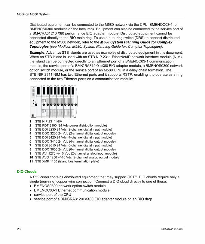
Example: Advantys STB islands are used as examples of distributed equipment in this document. When an STB island is used with an STB NIP 2311 EtherNet/IP network interface module (NIM), the island can be connected directly to an Ethernet port of a BMENOC03•1 communication module, the service port of a BM•CRA312•0 eX80 EIO adapter module, a BMENOS0300 network option switch module, or the service port of an M580 CPU in a daisy chain formation. The STB NIP 2311 NIM has two Ethernet ports and it supports RSTP, enabling it to operate as a ring connected to the two Ethernet ports on a communication module:
1 STB NIP 2311 NIM2 STB PDT 3100 (24 Vdc power distribution module)3 STB DDI 3230 24 Vdc (2-channel digital input module)4 STB DDO 3200 24 Vdc (2-channel digital output module)5 STB DDI 3420 24 Vdc (4-channel digital input module)6 STB DDO 3410 24 Vdc (4-channel digital output module)7 STB DDI 3610 24 Vdc (6-channel digital input module)8 STB DDO 3600 24 Vdc (6-channel digital output module)9 STB AVI 1270 +/-10 Vdc (2-channel analog input module)10 STB AVO 1250 +/-10 Vdc (2-channel analog output module)11 STB XMP 1100 (island bus termination plate)
DIO Clouds
A DIO cloud contains distributed equipment that may support RSTP. DIO clouds require only a single (non-ring) copper wire connection. Connect a DIO cloud directly to one of these: BMENOS0300 network option switch module BMENOC03•1 Ethernet communication module service port of the CPU service port of a BM•CRA312•0 eX80 EIO adapter module on an RIO drop
26 HRB62666 12/2015
Modicon M580 System
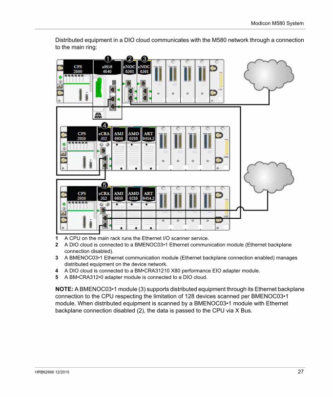
Distributed equipment in a DIO cloud communicates with the M580 network through a connection to the main ring:
1 A CPU on the main rack runs the Ethernet I/O scanner service.2 A DIO cloud is connected to a BMENOC03•1 Ethernet communication module (Ethernet backplane
connection disabled).3 A BMENOC03•1 Ethernet communication module (Ethernet backplane connection enabled) manages
distributed equipment on the device network.4 A DIO cloud is connected to a BM•CRA31210 X80 performance EIO adapter module.5 A BM•CRA312•0 adapter module is connected to a DIO cloud.
NOTE: A BMENOC03•1 module (3) supports distributed equipment through its Ethernet backplane connection to the CPU respecting the limitation of 128 devices scanned per BMENOC03•1 module. When distributed equipment is scanned by a BMENOC03•1 module with Ethernet backplane connection disabled (2), the data is passed to the CPU via X Bus.
HRB62666 12/2015 27
Modicon M580 System
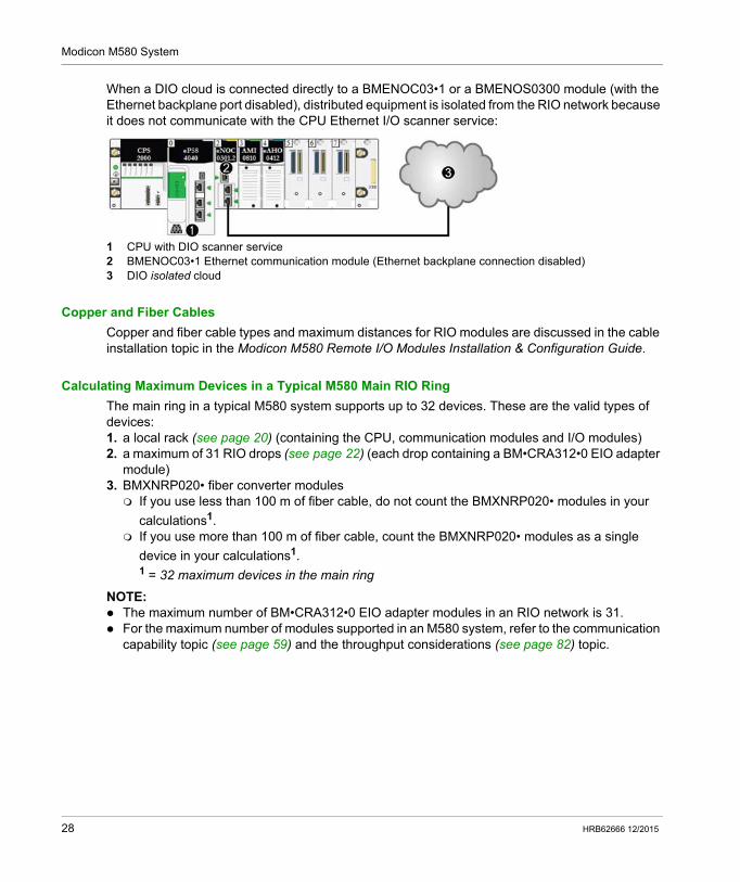
When a DIO cloud is connected directly to a BMENOC03•1 or a BMENOS0300 module (with the Ethernet backplane port disabled), distributed equipment is isolated from the RIO network because it does not communicate with the CPU Ethernet I/O scanner service:
1 CPU with DIO scanner service2 BMENOC03•1 Ethernet communication module (Ethernet backplane connection disabled)3 DIO isolated cloud
Copper and Fiber Cables
Copper and fiber cable types and maximum distances for RIO modules are discussed in the cable installation topic in the Modicon M580 Remote I/O Modules Installation & Configuration Guide.
Calculating Maximum Devices in a Typical M580 Main RIO Ring
The main ring in a typical M580 system supports up to 32 devices. These are the valid types of devices:1. a local rack (see page 20) (containing the CPU, communication modules and I/O modules)2. a maximum of 31 RIO drops (see page 22) (each drop containing a BM•CRA312•0 EIO adapter
module)3. BMXNRP020• fiber converter modules If you use less than 100 m of fiber cable, do not count the BMXNRP020• modules in your
calculations1. If you use more than 100 m of fiber cable, count the BMXNRP020• modules as a single
device in your calculations1.1 = 32 maximum devices in the main ring
NOTE: The maximum number of BM•CRA312•0 EIO adapter modules in an RIO network is 31. For the maximum number of modules supported in an M580 system, refer to the communication
capability topic (see page 59) and the throughput considerations (see page 82) topic.
28 HRB62666 12/2015
Modicon M580 System
Typical Modicon M580 RIO/DIO Network Topologies
Introduction
This topic discusses some of the more common DIO and RIO network topologies that use typical system components (see page 20).
DIO Daisy Chain and DIO Daisy Chain Loop
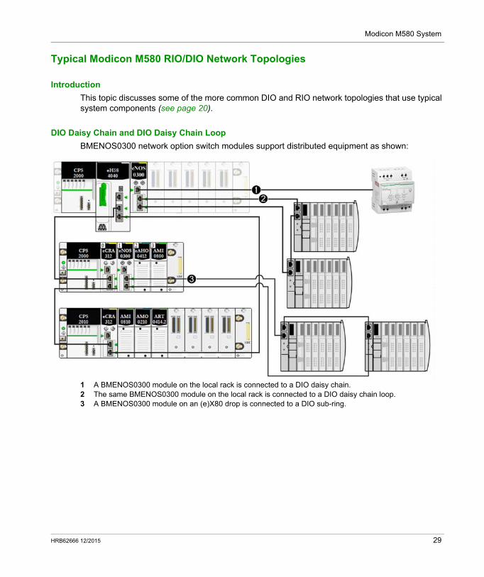
BMENOS0300 network option switch modules support distributed equipment as shown:
1 A BMENOS0300 module on the local rack is connected to a DIO daisy chain.2 The same BMENOS0300 module on the local rack is connected to a DIO daisy chain loop.3 A BMENOS0300 module on an (e)X80 drop is connected to a DIO sub-ring.
HRB62666 12/2015 29
Modicon M580 System
DIO Daisy Chain and DIO Clouds
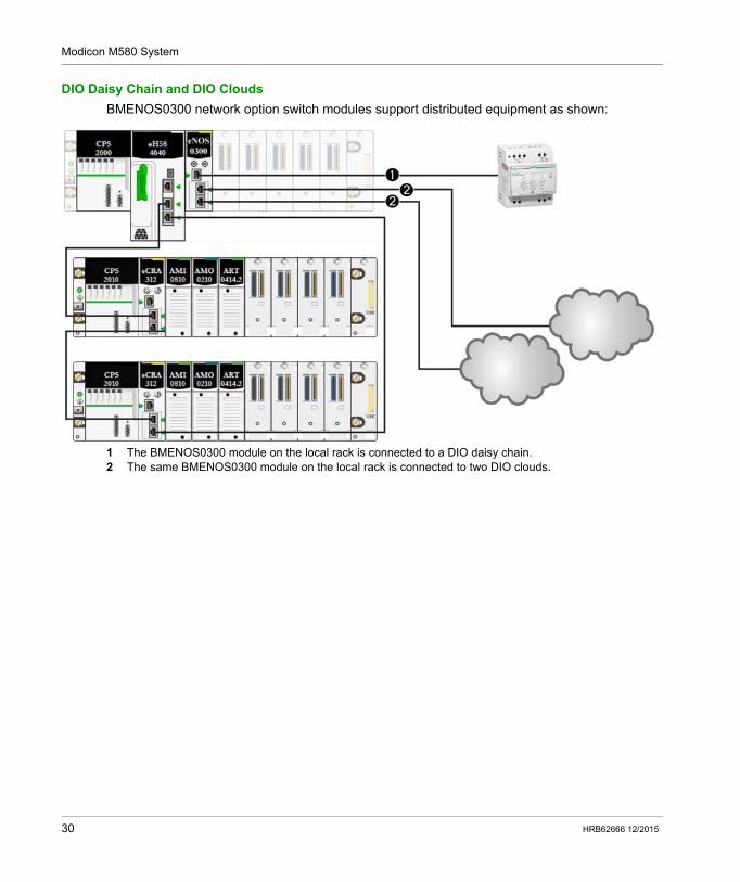
BMENOS0300 network option switch modules support distributed equipment as shown:
1 The BMENOS0300 module on the local rack is connected to a DIO daisy chain.2 The same BMENOS0300 module on the local rack is connected to two DIO clouds.
30 HRB62666 12/2015
Modicon M580 System
DIO Daisy Chain and DIO Multiple Daisy Chain Loops
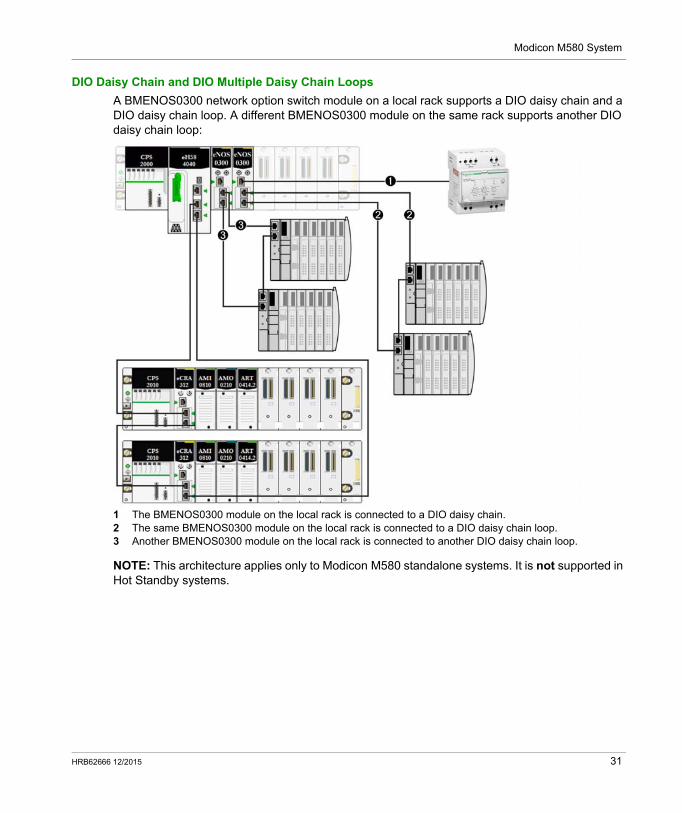
A BMENOS0300 network option switch module on a local rack supports a DIO daisy chain and a DIO daisy chain loop. A different BMENOS0300 module on the same rack supports another DIO daisy chain loop:
1 The BMENOS0300 module on the local rack is connected to a DIO daisy chain.2 The same BMENOS0300 module on the local rack is connected to a DIO daisy chain loop.3 Another BMENOS0300 module on the local rack is connected to another DIO daisy chain loop.
NOTE: This architecture applies only to Modicon M580 standalone systems. It is not supported in Hot Standby systems.
HRB62666 12/2015 31
Modicon M580 System
Modicon M580 DIO Connections
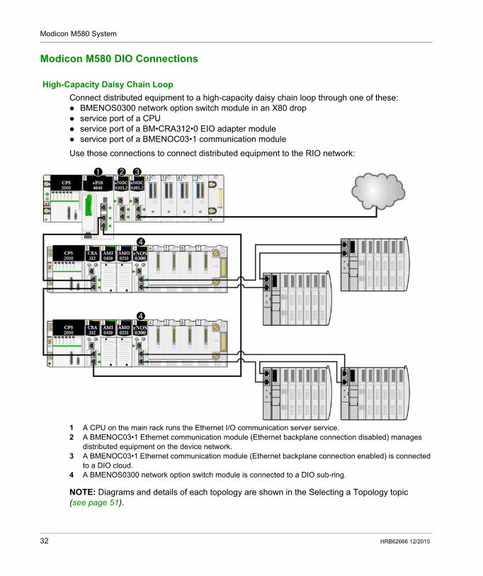
High-Capacity Daisy Chain Loop
Connect distributed equipment to a high-capacity daisy chain loop through one of these: BMENOS0300 network option switch module in an X80 drop service port of a CPU service port of a BM•CRA312•0 EIO adapter module service port of a BMENOC03•1 communication module
Use those connections to connect distributed equipment to the RIO network:
1 A CPU on the main rack runs the Ethernet I/O communication server service.2 A BMENOC03•1 Ethernet communication module (Ethernet backplane connection disabled) manages
distributed equipment on the device network.3 A BMENOC03•1 Ethernet communication module (Ethernet backplane connection enabled) is connected
to a DIO cloud.4 A BMENOS0300 network option switch module is connected to a DIO sub-ring.
NOTE: Diagrams and details of each topology are shown in the Selecting a Topology topic (see page 51).
32 HRB62666 12/2015
Modicon M580 System
Modicon M580 System Features
Introduction
An M580 system can include software configuration, services, and features that you may already use in your existing system.
Unity Pro Software
Unity Pro software is used in an M580 system.
For detailed Unity Pro configuration procedures, refer to the respective Modicon M580 [Module] Installation and Configuration Guide.
CCOTF Function
The Change Configuration on the Fly (CCOTF) function allows I/O configuration changes in the Ethernet RIO drops when the CPU is in STOP or RUN mode.
Detailed information is available in the Modicon M580 Change Configuration on the Fly User Guide.
Time Stamping
For Modicon X80 RIO drops on an X Bus backplane (see page 20), time stamping is managed by a BMX ERT 1604 module installed on the RIO drop with a resolution of 1 ms. The BMXCRA31210 X80 performance EIO adapter module also manages this functionality.
For Modicon X80 RIO drops on an Ethernet backplane, time stamping is managed by a BMECRA31210 X80 performance EIO adapter module installed on the RIO drop with a resolution of 10 ms.
Inputs or outputs of X80 digital modules can be time stamped in an RIO drop with a BM• CRA 312 10 X80 EIO adapter module..
Local variables can be time stamped in the PAC.
The BMXCRA31210 and BMECRA31210 eX80 EIO adapter modules have the same resolution/accuracy for a given NTP server. The accuracy is better if a dedicated NTP server is used instead of an M580 CPU as the NTP server.
Ethernet Services
As mentioned previously, some CPUs support both RIO and DIO scanning services, and others support only DIO services. The Ethernet services that can be used on these classes of M580 CPU differ as follows:
Service CPUs that Support RIO CPUs that Support DIO
Security X X
IPConfig X X
RSTP X X
HRB62666 12/2015 33
Modicon M580 System
M580 modules communicate using these parameters, which can be configured with Unity Pro 10.0 or later. IP address (See the configuration topic in the respective Modicon M580 [Module] Installation
and Configuration Guide.)NOTE: The BM•CRA312•0 EIO adapter modules automatically receive an IP address. You cannot change this IP address on this screen. Open the Unity Pro CPU configuration screen to change the IP address.
RSTP (See the configuration topic in the respective Modicon M580 [Module] Installation and Configuration Guide.)
SNMP (See the configuration topic in the respective Modicon M580 [Module] Installation and Configuration Guide.)
service port (See the configuration topic in the respective Modicon M580 [Module] Installation and Configuration Guide.)
SNTP (See the configuration topic in the respective Modicon M580 [Module] Installation and Configuration User Guide.)
Explicit Messaging
M580 CPUs and Ethernet communication modules support explicit messaging via EtherNet/IP and Modbus TCP protocols. This feature is detailed in the respective Modicon M580 [Module] Installation and Configuration Guide.
Use explicit messaging for extended diagnostics. These are the methods for explicit messaging in M580 systems: EtherNet/IP or Modbus TCP explicit messaging using one of the following function blocks: READ_VAR WRITE_VAR DATA_EXCH
explicit messaging via the Unity Pro graphic user interface, as described in manuals such as the M580 Hardware Reference Guide and the BME NOC 03•1 Ethernet Communications Module Installation and Configuration Guide.
NOTE: For detailed information regarding these function blocks, refer to the Extended part in the Unity Pro Communication Block Library user manual.
SNMP X X
NTP X X
Switch (see note below.) — X
QoS — X
ServicePort X X
Advanced Settings — X
NOTE: Enable Ethernet (ETH) and backplane ports and select their respective baud rates.
Service CPUs that Support RIO CPUs that Support DIO
34 HRB62666 12/2015
Modicon M580 Standalone
Modules in an M580 System
HRB62666 12/2015
Modules in an M580 System
Chapter 2Modules in an M580 System
Overview
This chapter describes required and compatible modules in an M580 system.
What Is in This Chapter?
This chapter contains the following topics:
Topic Page
Modules and Switches in an M580 System 36
Modicon X80 I/O Modules 40
Distributed Equipment 48
HRB62666 12/2015 35
Modules in an M580 System
Modules and Switches in an M580 System
Ethernet Communication Modules
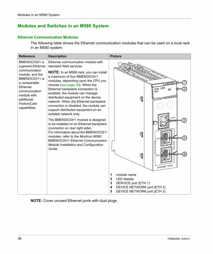
The following table shows the Ethernet communication modules that can be used on a local rack in an M580 system:
NOTE: Cover unused Ethernet ports with dust plugs.
Reference Description Picture
BMENOC0301 is a generic Ethernet communication module, and the BMENOC0311 is a comparable Ethernet communication module with additional FactoryCast capabilities.
Ethernet communication module with standard Web services
NOTE: In an M580 rack, you can install a maximum of four BMENOC03•1 modules, depending upon the CPU you choose (see page 59). When the Ethernet backplane connection is enabled, the module can manage distributed equipment on the device network. When the Ethernet backplane connection is disabled, the module can support distributed equipment on an isolated network only.
The BMENOC03•1 module is designed to be installed on an Ethernet backplane (connector on rear right side).For information about the BMENOC03•1 modules, refer to the Modicon M580 BMENOC03•1 Ethernet Communication Module Installation and Configuration Guide.
1 module name2 LED display3 SERVICE port (ETH 1)4 DEVICE NETWORK port (ETH 2)5 DEVICE NETWORK port (ETH 3)
36 HRB62666 12/2015

Modules in an M580 System
EIO Adapter Modules
The following X80 EIO adapter modules are used in an M580 system.
HRB62666 12/2015 37
Modules in an M580 System
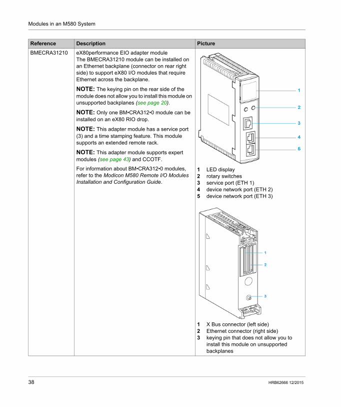
Reference Description Picture
BMECRA31210 eX80performance EIO adapter moduleThe BMECRA31210 module can be installed on an Ethernet backplane (connector on rear right side) to support eX80 I/O modules that require Ethernet across the backplane.
NOTE: The keying pin on the rear side of the module does not allow you to install this module on unsupported backplanes (see page 20).
NOTE: Only one BM•CRA312•0 module can be installed on an eX80 RIO drop.
NOTE: This adapter module has a service port (3) and a time stamping feature. This module supports an extended remote rack.
NOTE: This adapter module supports expert modules (see page 43) and CCOTF.
For information about BM•CRA312•0 modules, refer to the Modicon M580 Remote I/O Modules Installation and Configuration Guide.
1 LED display2 rotary switches3 service port (ETH 1)4 device network port (ETH 2)5 device network port (ETH 3)
1 X Bus connector (left side)2 Ethernet connector (right side)3 keying pin that does not allow you to
install this module on unsupported backplanes
38 HRB62666 12/2015
Modules in an M580 System
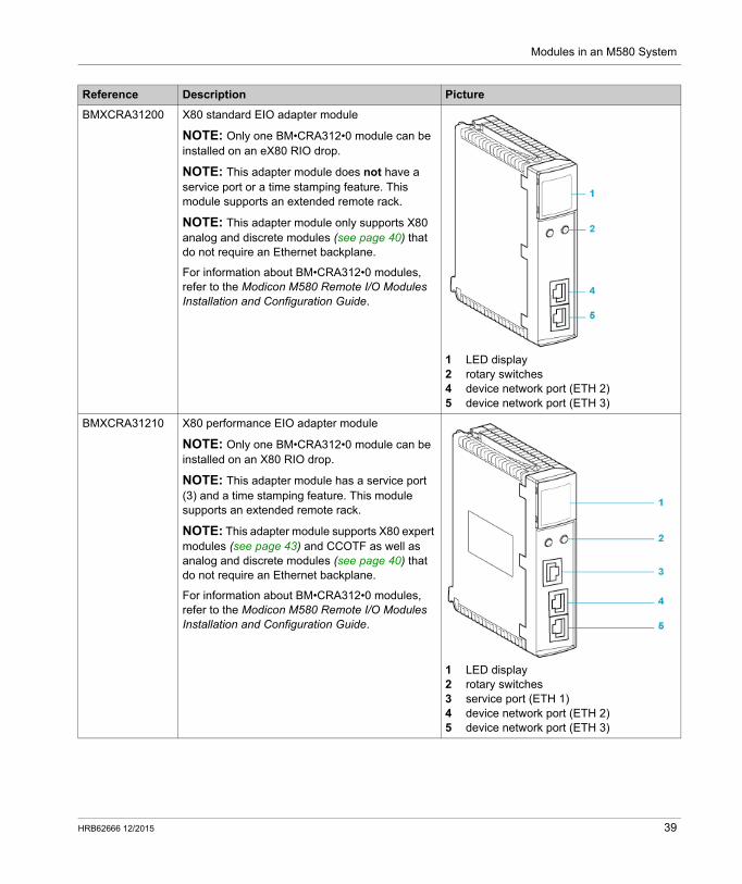
BMXCRA31200 X80 standard EIO adapter module
NOTE: Only one BM•CRA312•0 module can be installed on an eX80 RIO drop.
NOTE: This adapter module does not have a service port or a time stamping feature. This module supports an extended remote rack.
NOTE: This adapter module only supports X80 analog and discrete modules (see page 40) that do not require an Ethernet backplane.
For information about BM•CRA312•0 modules, refer to the Modicon M580 Remote I/O Modules Installation and Configuration Guide.
1 LED display2 rotary switches4 device network port (ETH 2)5 device network port (ETH 3)
BMXCRA31210 X80 performance EIO adapter module
NOTE: Only one BM•CRA312•0 module can be installed on an X80 RIO drop.
NOTE: This adapter module has a service port (3) and a time stamping feature. This module supports an extended remote rack.
NOTE: This adapter module supports X80 expert modules (see page 43) and CCOTF as well as analog and discrete modules (see page 40) that do not require an Ethernet backplane.
For information about BM•CRA312•0 modules, refer to the Modicon M580 Remote I/O Modules Installation and Configuration Guide.
1 LED display2 rotary switches3 service port (ETH 1)4 device network port (ETH 2)5 device network port (ETH 3)
Reference Description Picture
HRB62666 12/2015 39
Modules in an M580 System
Modicon X80 I/O Modules
Introduction
The following I/O modules can be mounted in local racks or RIO drops in an M580 system.
Some of these modules also contain embedded web pages that can be used for configuration and diagnostics. Web page descriptions are provided in the appropriate product documentation and in Unity Pro help.
NOTE: Conformally coated (hardened H) versions of many of these modules are also available.
Modicon X80 Analog and Discrete Modules
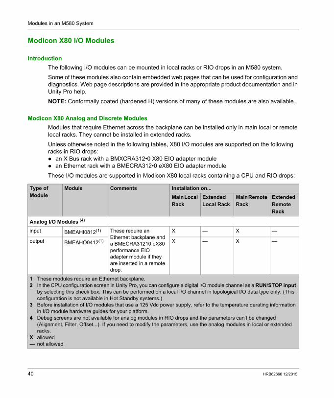
Modules that require Ethernet across the backplane can be installed only in main local or remote local racks. They cannot be installed in extended racks.
Unless otherwise noted in the following tables, X80 I/O modules are supported on the following racks in RIO drops: an X Bus rack with a BMXCRA312•0 X80 EIO adapter module an Ethernet rack with a BMECRA312•0 eX80 EIO adapter module
These I/O modules are supported in Modicon X80 local racks containing a CPU and RIO drops:
Type of Module
Module Comments Installation on...
Main Local Rack
Extended Local Rack
Main Remote Rack
Extended Remote Rack
Analog I/O Modules (4)
input BMEAHI0812(1) These require an Ethernet backplane and a BMECRA31210 eX80 performance EIO adapter module if they are inserted in a remote drop.
X — X —
output BMEAHO0412(1) X — X —
1 These modules require an Ethernet backplane.2 In the CPU configuration screen in Unity Pro, you can configure a digital I/O module channel as a RUN/STOP input
by selecting this check box. This can be performed on a local I/O channel in topological I/O data type only. (This configuration is not available in Hot Standby systems.)
3 Before installation of I/O modules that use a 125 Vdc power supply, refer to the temperature derating information in I/O module hardware guides for your platform.
4 Debug screens are not available for analog modules in RIO drops and the parameters can’t be changed (Alignment, Filter, Offset...). If you need to modify the parameters, use the analog modules in local or extended racks.
X allowed— not allowed
40 HRB62666 12/2015
Modules in an M580 System
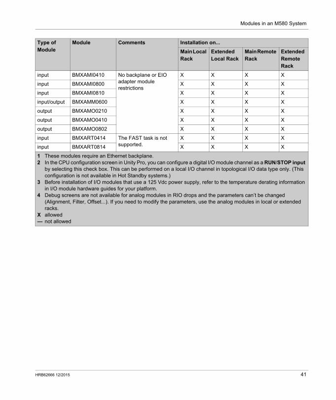
input BMXAMI0410 No backplane or EIO adapter module restrictions
X X X X
input BMXAMI0800 X X X X
input BMXAMI0810 X X X X
input/output BMXAMM0600 X X X X
output BMXAMO0210 X X X X
output BMXAMO0410 X X X X
output BMXAMO0802 X X X X
input BMXART0414 The FAST task is not supported.
X X X X
input BMXART0814 X X X X
Type of Module
Module Comments Installation on...
Main Local Rack
Extended Local Rack
Main Remote Rack
Extended Remote Rack
1 These modules require an Ethernet backplane.2 In the CPU configuration screen in Unity Pro, you can configure a digital I/O module channel as a RUN/STOP input
by selecting this check box. This can be performed on a local I/O channel in topological I/O data type only. (This configuration is not available in Hot Standby systems.)
3 Before installation of I/O modules that use a 125 Vdc power supply, refer to the temperature derating information in I/O module hardware guides for your platform.
4 Debug screens are not available for analog modules in RIO drops and the parameters can’t be changed (Alignment, Filter, Offset...). If you need to modify the parameters, use the analog modules in local or extended racks.
X allowed— not allowed
HRB62666 12/2015 41
Modules in an M580 System
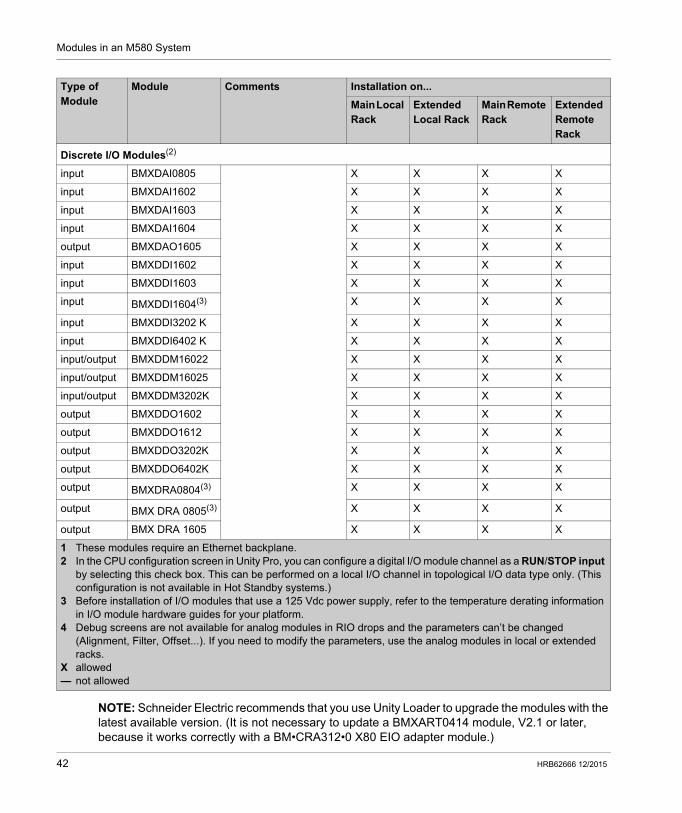
NOTE: Schneider Electric recommends that you use Unity Loader to upgrade the modules with the latest available version. (It is not necessary to update a BMXART0414 module, V2.1 or later, because it works correctly with a BM•CRA312•0 X80 EIO adapter module.)
Discrete I/O Modules(2)
input BMXDAI0805 X X X X
input BMXDAI1602 X X X X
input BMXDAI1603 X X X X
input BMXDAI1604 X X X X
output BMXDAO1605 X X X X
input BMXDDI1602 X X X X
input BMXDDI1603 X X X X
input BMXDDI1604(3) X X X X
input BMXDDI3202 K X X X X
input BMXDDI6402 K X X X X
input/output BMXDDM16022 X X X X
input/output BMXDDM16025 X X X X
input/output BMXDDM3202K X X X X
output BMXDDO1602 X X X X
output BMXDDO1612 X X X X
output BMXDDO3202K X X X X
output BMXDDO6402K X X X X
output BMXDRA0804(3) X X X X
output BMX DRA 0805(3) X X X X
output BMX DRA 1605 X X X X
Type of Module
Module Comments Installation on...
Main Local Rack
Extended Local Rack
Main Remote Rack
Extended Remote Rack
1 These modules require an Ethernet backplane.2 In the CPU configuration screen in Unity Pro, you can configure a digital I/O module channel as a RUN/STOP input
by selecting this check box. This can be performed on a local I/O channel in topological I/O data type only. (This configuration is not available in Hot Standby systems.)
3 Before installation of I/O modules that use a 125 Vdc power supply, refer to the temperature derating information in I/O module hardware guides for your platform.
4 Debug screens are not available for analog modules in RIO drops and the parameters can’t be changed (Alignment, Filter, Offset...). If you need to modify the parameters, use the analog modules in local or extended racks.
X allowed— not allowed
42 HRB62666 12/2015
Modules in an M580 System
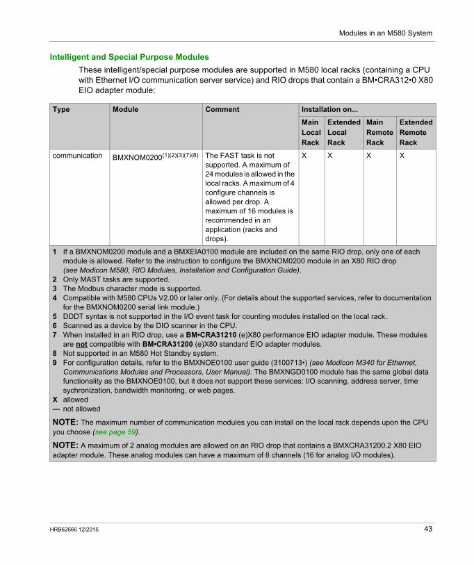
Intelligent and Special Purpose Modules
These intelligent/special purpose modules are supported in M580 local racks (containing a CPU with Ethernet I/O communication server service) and RIO drops that contain a BM•CRA312•0 X80 EIO adapter module:
Type Module Comment Installation on...
Main Local Rack
Extended Local Rack
Main Remote Rack
Extended Remote Rack
communication BMXNOM0200(1)(2)(3)(7)(8) The FAST task is not supported. A maximum of 24 modules is allowed in the local racks. A maximum of 4 configure channels is allowed per drop. A maximum of 16 modules is recommended in an application (racks and drops).
X X X X
1 If a BMXNOM0200 module and a BMXEIA0100 module are included on the same RIO drop, only one of each module is allowed. Refer to the instruction to configure the BMXNOM0200 module in an X80 RIO drop (see Modicon M580, RIO Modules, Installation and Configuration Guide).
2 Only MAST tasks are supported.3 The Modbus character mode is supported.4 Compatible with M580 CPUs V2.00 or later only. (For details about the supported services, refer to documentation
for the BMXNOM0200 serial link module.)5 DDDT syntax is not supported in the I/O event task for counting modules installed on the local rack.6 Scanned as a device by the DIO scanner in the CPU.7 When installed in an RIO drop, use a BM•CRA31210 (e)X80 performance EIO adapter module. These modules
are not compatible with BM•CRA31200 (e)X80 standard EIO adapter modules.8 Not supported in an M580 Hot Standby system.9 For configuration details, refer to the BMXNOE0100 user guide (3100713•) (see Modicon M340 for Ethernet,
Communications Modules and Processors, User Manual). The BMXNGD0100 module has the same global data functionality as the BMXNOE0100, but it does not support these services: I/O scanning, address server, time sychronization, bandwidth monitoring, or web pages.
X allowed— not allowed
NOTE: The maximum number of communication modules you can install on the local rack depends upon the CPU you choose (see page 59).
NOTE: A maximum of 2 analog modules are allowed on an RIO drop that contains a BMXCRA31200.2 X80 EIO adapter module. These analog modules can have a maximum of 8 channels (16 for analog I/O modules).
HRB62666 12/2015 43
Modules in an M580 System
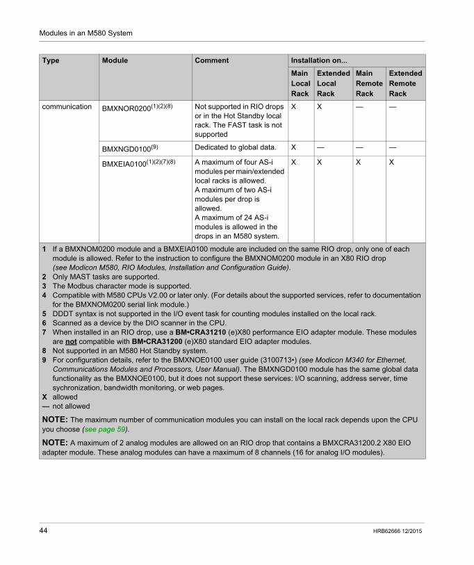
communication BMXNOR0200(1)(2)(8) Not supported in RIO drops or in the Hot Standby local rack. The FAST task is not supported
X X — —
BMXNGD0100(9) Dedicated to global data. X — — —
BMXEIA0100(1)(2)(7)(8) A maximum of four AS-i modules per main/extended local racks is allowed.A maximum of two AS-i modules per drop is allowed.A maximum of 24 AS-i modules is allowed in the drops in an M580 system.
X X X X
Type Module Comment Installation on...
Main Local Rack
Extended Local Rack
Main Remote Rack
Extended Remote Rack
1 If a BMXNOM0200 module and a BMXEIA0100 module are included on the same RIO drop, only one of each module is allowed. Refer to the instruction to configure the BMXNOM0200 module in an X80 RIO drop (see Modicon M580, RIO Modules, Installation and Configuration Guide).
2 Only MAST tasks are supported.3 The Modbus character mode is supported.4 Compatible with M580 CPUs V2.00 or later only. (For details about the supported services, refer to documentation
for the BMXNOM0200 serial link module.)5 DDDT syntax is not supported in the I/O event task for counting modules installed on the local rack.6 Scanned as a device by the DIO scanner in the CPU.7 When installed in an RIO drop, use a BM•CRA31210 (e)X80 performance EIO adapter module. These modules
are not compatible with BM•CRA31200 (e)X80 standard EIO adapter modules.8 Not supported in an M580 Hot Standby system.9 For configuration details, refer to the BMXNOE0100 user guide (3100713•) (see Modicon M340 for Ethernet,
Communications Modules and Processors, User Manual). The BMXNGD0100 module has the same global data functionality as the BMXNOE0100, but it does not support these services: I/O scanning, address server, time sychronization, bandwidth monitoring, or web pages.
X allowed— not allowed
NOTE: The maximum number of communication modules you can install on the local rack depends upon the CPU you choose (see page 59).
NOTE: A maximum of 2 analog modules are allowed on an RIO drop that contains a BMXCRA31200.2 X80 EIO adapter module. These analog modules can have a maximum of 8 channels (16 for analog I/O modules).
44 HRB62666 12/2015
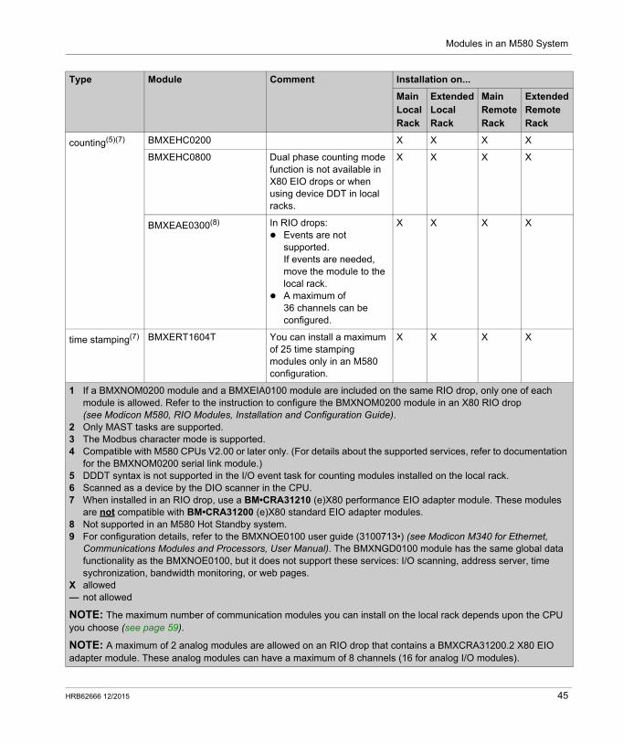
Modules in an M580 System
counting(5)(7) BMXEHC0200 X X X X
BMXEHC0800 Dual phase counting mode function is not available in X80 EIO drops or when using device DDT in local racks.
X X X X
BMXEAE0300(8) In RIO drops: Events are not
supported.If events are needed, move the module to the local rack.
A maximum of 36 channels can be configured.
X X X X
time stamping(7) BMXERT1604T You can install a maximum of 25 time stamping modules only in an M580 configuration.
X X X X
Type Module Comment Installation on...
Main Local Rack
Extended Local Rack
Main Remote Rack
Extended Remote Rack
1 If a BMXNOM0200 module and a BMXEIA0100 module are included on the same RIO drop, only one of each module is allowed. Refer to the instruction to configure the BMXNOM0200 module in an X80 RIO drop (see Modicon M580, RIO Modules, Installation and Configuration Guide).
2 Only MAST tasks are supported.3 The Modbus character mode is supported.4 Compatible with M580 CPUs V2.00 or later only. (For details about the supported services, refer to documentation
for the BMXNOM0200 serial link module.)5 DDDT syntax is not supported in the I/O event task for counting modules installed on the local rack.6 Scanned as a device by the DIO scanner in the CPU.7 When installed in an RIO drop, use a BM•CRA31210 (e)X80 performance EIO adapter module. These modules
are not compatible with BM•CRA31200 (e)X80 standard EIO adapter modules.8 Not supported in an M580 Hot Standby system.9 For configuration details, refer to the BMXNOE0100 user guide (3100713•) (see Modicon M340 for Ethernet,
Communications Modules and Processors, User Manual). The BMXNGD0100 module has the same global data functionality as the BMXNOE0100, but it does not support these services: I/O scanning, address server, time sychronization, bandwidth monitoring, or web pages.
X allowed— not allowed
NOTE: The maximum number of communication modules you can install on the local rack depends upon the CPU you choose (see page 59).
NOTE: A maximum of 2 analog modules are allowed on an RIO drop that contains a BMXCRA31200.2 X80 EIO adapter module. These analog modules can have a maximum of 8 channels (16 for analog I/O modules).
HRB62666 12/2015 45
Modules in an M580 System
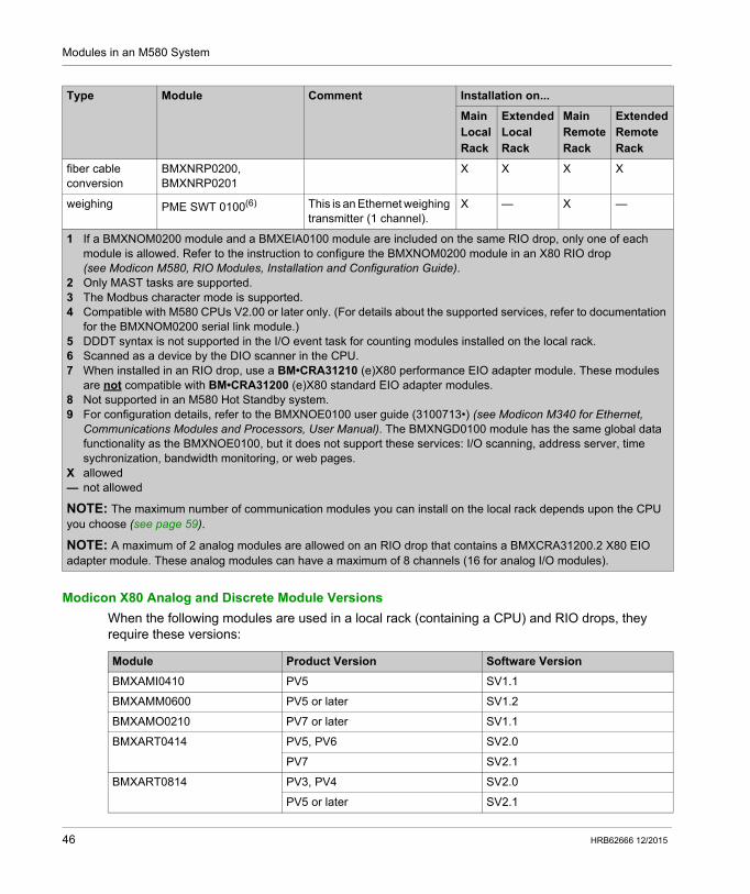
Modicon X80 Analog and Discrete Module Versions
When the following modules are used in a local rack (containing a CPU) and RIO drops, they require these versions:
fiber cable conversion
BMXNRP0200, BMXNRP0201
X X X X
weighing PME SWT 0100(6) This is an Ethernet weighing transmitter (1 channel).
X — X —
Type Module Comment Installation on...
Main Local Rack
Extended Local Rack
Main Remote Rack
Extended Remote Rack
1 If a BMXNOM0200 module and a BMXEIA0100 module are included on the same RIO drop, only one of each module is allowed. Refer to the instruction to configure the BMXNOM0200 module in an X80 RIO drop (see Modicon M580, RIO Modules, Installation and Configuration Guide).
2 Only MAST tasks are supported.3 The Modbus character mode is supported.4 Compatible with M580 CPUs V2.00 or later only. (For details about the supported services, refer to documentation
for the BMXNOM0200 serial link module.)5 DDDT syntax is not supported in the I/O event task for counting modules installed on the local rack.6 Scanned as a device by the DIO scanner in the CPU.7 When installed in an RIO drop, use a BM•CRA31210 (e)X80 performance EIO adapter module. These modules
are not compatible with BM•CRA31200 (e)X80 standard EIO adapter modules.8 Not supported in an M580 Hot Standby system.9 For configuration details, refer to the BMXNOE0100 user guide (3100713•) (see Modicon M340 for Ethernet,
Communications Modules and Processors, User Manual). The BMXNGD0100 module has the same global data functionality as the BMXNOE0100, but it does not support these services: I/O scanning, address server, time sychronization, bandwidth monitoring, or web pages.
X allowed— not allowed
NOTE: The maximum number of communication modules you can install on the local rack depends upon the CPU you choose (see page 59).
NOTE: A maximum of 2 analog modules are allowed on an RIO drop that contains a BMXCRA31200.2 X80 EIO adapter module. These analog modules can have a maximum of 8 channels (16 for analog I/O modules).
Module Product Version Software Version
BMXAMI0410 PV5 SV1.1
BMXAMM0600 PV5 or later SV1.2
BMXAMO0210 PV7 or later SV1.1
BMXART0414 PV5, PV6 SV2.0
PV7 SV2.1
BMXART0814 PV3, PV4 SV2.0
PV5 or later SV2.1
46 HRB62666 12/2015
Modules in an M580 System
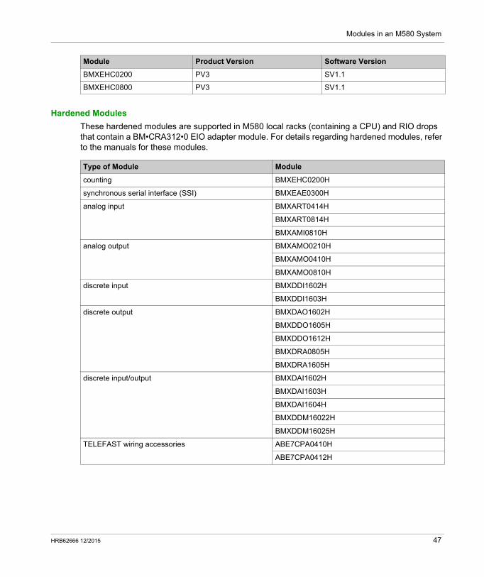
Hardened Modules
These hardened modules are supported in M580 local racks (containing a CPU) and RIO drops that contain a BM•CRA312•0 EIO adapter module. For details regarding hardened modules, refer to the manuals for these modules.
BMXEHC0200 PV3 SV1.1
BMXEHC0800 PV3 SV1.1
Module Product Version Software Version
Type of Module Module
counting BMXEHC0200H
synchronous serial interface (SSI) BMXEAE0300H
analog input BMXART0414H
BMXART0814H
BMXAMI0810H
analog output BMXAMO0210H
BMXAMO0410H
BMXAMO0810H
discrete input BMXDDI1602H
BMXDDI1603H
discrete output BMXDAO1602H
BMXDDO1605H
BMXDDO1612H
BMXDRA0805H
BMXDRA1605H
discrete input/output BMXDAI1602H
BMXDAI1603H
BMXDAI1604H
BMXDDM16022H
BMXDDM16025H
TELEFAST wiring accessories ABE7CPA0410H
ABE7CPA0412H
HRB62666 12/2015 47
Modules in an M580 System
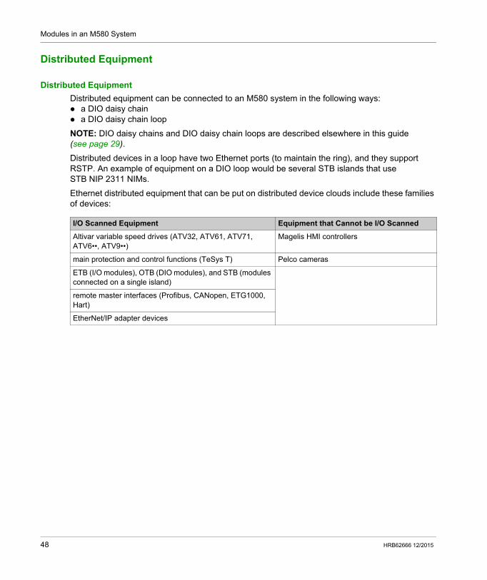
Distributed Equipment
Distributed Equipment
Distributed equipment can be connected to an M580 system in the following ways: a DIO daisy chain a DIO daisy chain loop
NOTE: DIO daisy chains and DIO daisy chain loops are described elsewhere in this guide (see page 29).
Distributed devices in a loop have two Ethernet ports (to maintain the ring), and they support RSTP. An example of equipment on a DIO loop would be several STB islands that use STB NIP 2311 NIMs.
Ethernet distributed equipment that can be put on distributed device clouds include these families of devices:
I/O Scanned Equipment Equipment that Cannot be I/O Scanned
Altivar variable speed drives (ATV32, ATV61, ATV71, ATV6••, ATV9••)
Magelis HMI controllers
main protection and control functions (TeSys T) Pelco cameras
ETB (I/O modules), OTB (DIO modules), and STB (modules connected on a single island)
remote master interfaces (Profibus, CANopen, ETG1000, Hart)
EtherNet/IP adapter devices
48 HRB62666 12/2015
Modicon M580 Standalone
Planning and Designing an M580 Network
HRB62666 12/2015
Planning and Designing a Typical M580 Network
Part IIPlanning and Designing a Typical M580 Network
Introduction
This part describes the process of selecting the proper topology for your system, as well as the limitations involved in constructing your network and the role of determinism in a typical RIO network.
What Is in This Part?
This part contains the following chapters:
Chapter Chapter Name Page
3 Selecting the Correct Topology 51
4 Performance 79
HRB62666 12/2015 49

Planning and Designing an M580 Network
50 HRB62666 12/2015
Modicon M580 Standalone
Selecting the Correct Topology
HRB62666 12/2015
Selecting the Correct Topology
Chapter 3Selecting the Correct Topology
Overview
An M580 system provides deterministic services to remote I/O drops and to individual RIO modules. Distributed equipment does not have the same level of determinism, but it can participate on an RIO network without disrupting the determinism of the RIO modules.
In order to achieve this determinism, the RIO network follows a set of simple rules that are explained in this chapter. One CPU with Ethernet I/O scanner service is installed in the local rack. One BM•CRA312•0 eX80 EIO adapter module is installed in each RIO drop. Follow the rules regarding the maximum number of devices allowed (e.g., 32 devices, in the
main ring, including the local rack, and 31 RIO drops in the RIO network), the types of cables you select, and respect Unity Pro messages during programming and diagnostic checks (see page 111).
Optional elements include a maximum of six BMENOC03•1 Ethernet communication modules on the local rack only (see page 59) and a maximum of six BMENOS0300 modules on the local racks and RIO drops.)
Each M580 CPU supports only 1 Ethernet RIO network. This section helps you select the RIO network that allows improved response time for remote equipment operations.
In addition, preferred DIO network topologies are discussed in detail so that you can construct a device network that works harmoniously with the RIO network's deterministic operation.
NOTE: The architectures described in this document have been tested and validated in various scenarios. If you intend to use architectures different than the ones described in this document, test and validate them thoroughly before implementing.
NOTE: To use a dual-ring switch (DRS) to connect distributed equipment to the M580 network, refer to the M580 System Planning Guide for Complex Topologies (see Modicon M580, System Planning Guide for, Complex Topologies).
HRB62666 12/2015 51
Selecting the Correct Topology
What Is in This Chapter?
This chapter contains the following topics:
Topic Page
Project Life Cycle 53
Planning the Appropriate Network Topology 54
Selecting a CPU for your M580 System 59
Planning an Isolated DIO Network 62
Adding an Independent DIO Network 63
Planning a Simple Daisy Chain Loop 65
Local Rack Communication Module Installation 67
Using Premium Racks in an M580 System 69
Using Fiber Converter Modules 75
52 HRB62666 12/2015
Selecting the Correct Topology
Project Life Cycle
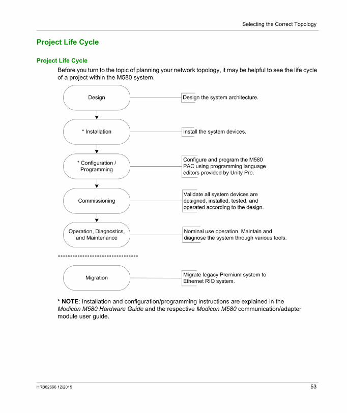
Project Life Cycle
Before you turn to the topic of planning your network topology, it may be helpful to see the life cycle of a project within the M580 system.
* NOTE: Installation and configuration/programming instructions are explained in the Modicon M580 Hardware Guide and the respective Modicon M580 communication/adapter module user guide.
HRB62666 12/2015 53
Selecting the Correct Topology
Planning the Appropriate Network Topology
Key Points when Planning a Topology
Consider these key points when you choose an M580 network topology: distance between two contiguous drops (and the potential need for DRSs or BMXNRP020• fiber
converter modules and fiber cable on the main ring) ring or star network topology (A DIO cloud with distributed equipment in a star topology can
communicate with an M580 network.) local rack configuration distributed equipment requirements isolation requirements (e.g., if the local rack and the drops are on different grounding systems) redundancy requirements for the main ring / sub-ring connections
These points are discussed in the following paragraphs.
Distance Between Two Drops
The distance between two drops determines the choice of physical layer.
If you are using copper cable, the maximum distance between two contiguous drops is 100 m. If the drops are more than 100 m apart, use 1 or more BMXNRP020• fiber converter modules to convert copper cable to fiber. A fiber cable can run as long as 15 km (for single-mode fiber).
54 HRB62666 12/2015
Selecting the Correct Topology
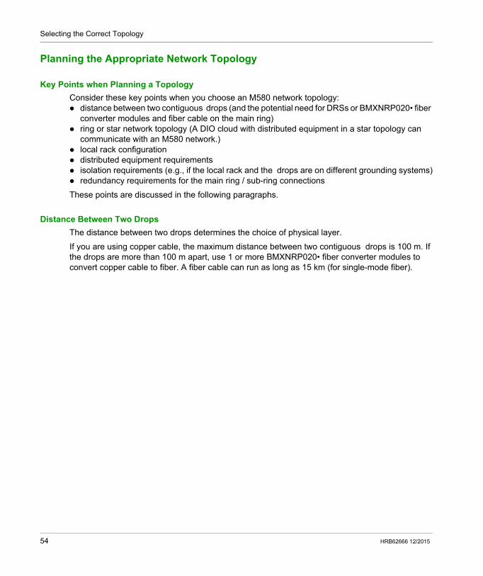
If Distance Between Two Remote Drops is Less than 100 m...
A copper Ethernet network provides a valid solution:
Note: The solid line represents copper wire.1 main ring2 CPU with Ethernet I/O scanner service on the local rack3 RIO drop (including a BM• CRA 312 •0 X80 EIO adapter module) on the main ring4 BMXNRP020• fiber converter module
HRB62666 12/2015 55
Selecting the Correct Topology
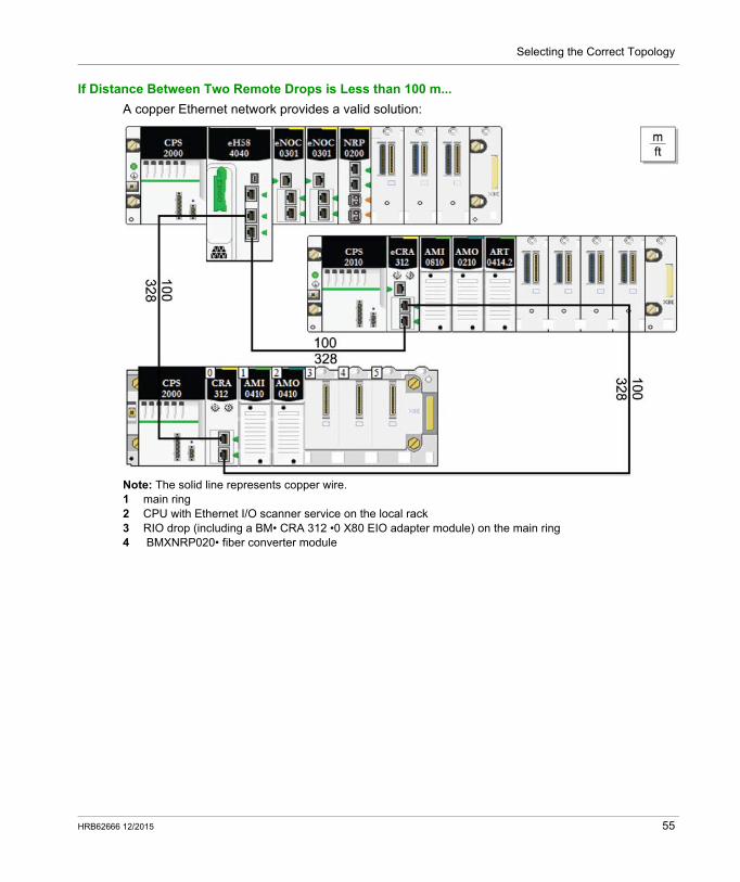
If Distance Between Two Remote Drops is More than 100 m...
Use BMXNRP020• fiber converter modules to increase the distance between two contiguous RIO modules, including the distance between the CPU and an RIO drop. To connect the fiber to the copper cables, insert a BMXNRP020• module at each end of the fiber link. Thus, two BMXNRP020• modules establish a single fiber link:
1 CPU with Ethernet I/O scanner service on the local rack2 BMXNRP020• fiber converter module on the local rack connected to an RIO drop on the main ring via fiber
cable3 (dashed line): fiber portion of the main ring4 (solid line): copper portion of the main ring5 BMXNRP020• module on an RIO drop connected to the main ring via fiber cable6 BMXNRP020• module on an RIO drop connected to the main ring via copper and fiber cable
NOTE: Use multi-mode fiber to connect the BMXNRP020• module to the main ring if the distance
between the local rack and the RIO drop is less than 2 km.
You cannot use BMXNRP020• modules to connect RIO or DIO sub-rings to the main ring.
56 HRB62666 12/2015
Selecting the Correct Topology
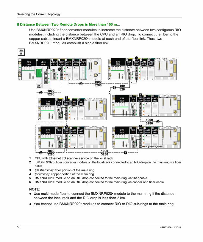
Using Fiber Converter Modules
Install fiber converter modules to extend the distance between the local rack and the first RIO drop on the main ring:
Close the ring:
Install fiber converter modules to extend the distance between RIO drops on the main ring or a sub-ring:
Step Action
1 Install a BMXNRP020• fiber converter module on a local rack.
2 Connect the BMXNRP020• module on the local rack via copper cable to the CPU.
3 Install a BMXNRP020• module on the first RIO drop on the main ring.
4 Connect the fiber cable between the BMXNRP020• module on the local rack and the BMXNRP020• module at the RIO drop. The BMXNRP020• module uses small form-factor plugs (SFPs) (transceivers) for the fiber ports. Choose single-mode or multi-mode SFPs. Use multi-mode fiber and a (BMXNRP0200) module to connect the BMXNRP020• module to the
main ring if the distance between the BMXNRP020• and the next Ethernet RIO drop is less than 2 km.
Use the single-mode fiber module (BMXNRP0201) to connect the BMXNRP020• module to the main ring if the distance between the BMXNRP020• and the next Ethernet RIO drop is between 2 km and 15 km.
5 Interlink the two copper ports of the BMXNRP020• module with the two Ethernet ports of the BM•CRA312•0 X80 EIO adapter module on the RIO drop.
6 To extend the distance between other RIO drops on the main ring, connect the BMXNRP020• module on an RIO drop to a BMXNRP020• module on the next drop. Then, follow the above step.
Step Action
1 Interlink a copper port on the BMXNRP020• module with an Ethernet port on the BM•CRA312•0 X80 EIO adapter module on the last RIO drop.
2 Connect the BMXNRP020• module on the RIO drop via fiber cable to the BMXNRP020• module on the local rack.
Step Action
1 Install BMXNRP020• modules on the two RIO drops for which you wish to extend the distance.
2 Connect the BMXNRP020• module on one drop to the BMXNRP020• module on the next drop. The BMXNRP020• module uses small form-factor plugs (SFPs) (transceivers) for the fiber ports. Choose single-mode or multi-mode SFPs. Use the multi-mode fiber module (BMXNRP0200) to connect the BMXNRP020• module to the ring
if the distance between the BMXNRP020• and the next drop is less than 2 km. Use the single-mode fiber module (BMXNRP0201) to connect the BMXNRP020• module to the
ring if the distance between the BMXNRP020• and the next drop is in the range 2 km ... 5 km.
3 Interlink the two copper ports of the BMXNRP020• module with the two Ethernet ports of the BM•CRA312•0 on the drop.
4 To extend the distance between other RIO drops on a ring, repeat steps 1-3.
HRB62666 12/2015 57

Selecting the Correct Topology
Isolation Requirements
If isolation is required in your network (e.g., if the local rack and RIO drops are on different grounding systems), then use fiber cable to connect devices that are on separate grounding systems.
Refer to the ground connections information in the Grounding and Electromagnetic Compatibility of PLC Systems Basics Principles and Measures User Manual (33002439) to comply with EMC certifications and deliver expected performance.
DANGERELECTRICAL SHOCK HAZARD
Switch off the power supply at both ends of the PAC connection, and lock out and tag out both the power sources.
In case lock out and tag out are not available, ensure that the power sources cannot be inadvertently switched on.
Use suitable insulation equipment when inserting or removing all or part of this equipment.
Failure to follow these instructions will result in death or serious injury.
58 HRB62666 12/2015
Selecting the Correct Topology
Selecting a CPU for your M580 System
Introduction
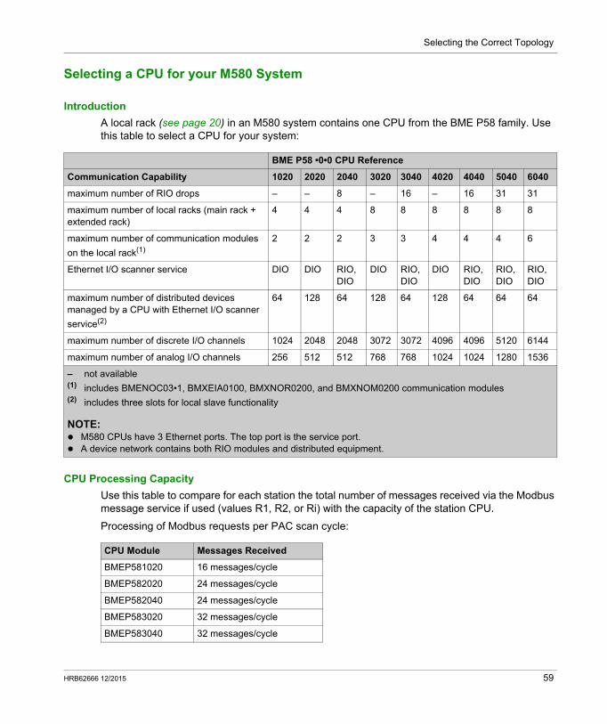
A local rack (see page 20) in an M580 system contains one CPU from the BME P58 family. Use this table to select a CPU for your system:
CPU Processing Capacity
Use this table to compare for each station the total number of messages received via the Modbus message service if used (values R1, R2, or Ri) with the capacity of the station CPU.
Processing of Modbus requests per PAC scan cycle:
BME P58 •0•0 CPU Reference
Communication Capability 1020 2020 2040 3020 3040 4020 4040 5040 6040
maximum number of RIO drops – – 8 – 16 – 16 31 31
maximum number of local racks (main rack + extended rack)
4 4 4 8 8 8 8 8 8
maximum number of communication modules
on the local rack(1)
2 2 2 3 3 4 4 4 6
Ethernet I/O scanner service DIO DIO RIO, DIO
DIO RIO, DIO
DIO RIO, DIO
RIO, DIO
RIO, DIO
maximum number of distributed devices managed by a CPU with Ethernet I/O scanner
service(2)
64 128 64 128 64 128 64 64 64
maximum number of discrete I/O channels 1024 2048 2048 3072 3072 4096 4096 5120 6144
maximum number of analog I/O channels 256 512 512 768 768 1024 1024 1280 1536
– not available(1) includes BMENOC03•1, BMXEIA0100, BMXNOR0200, and BMXNOM0200 communication modules(2) includes three slots for local slave functionality
NOTE: M580 CPUs have 3 Ethernet ports. The top port is the service port. A device network contains both RIO modules and distributed equipment.
CPU Module Messages Received
BMEP581020 16 messages/cycle
BMEP582020 24 messages/cycle
BMEP582040 24 messages/cycle
BMEP583020 32 messages/cycle
BMEP583040 32 messages/cycle
HRB62666 12/2015 59
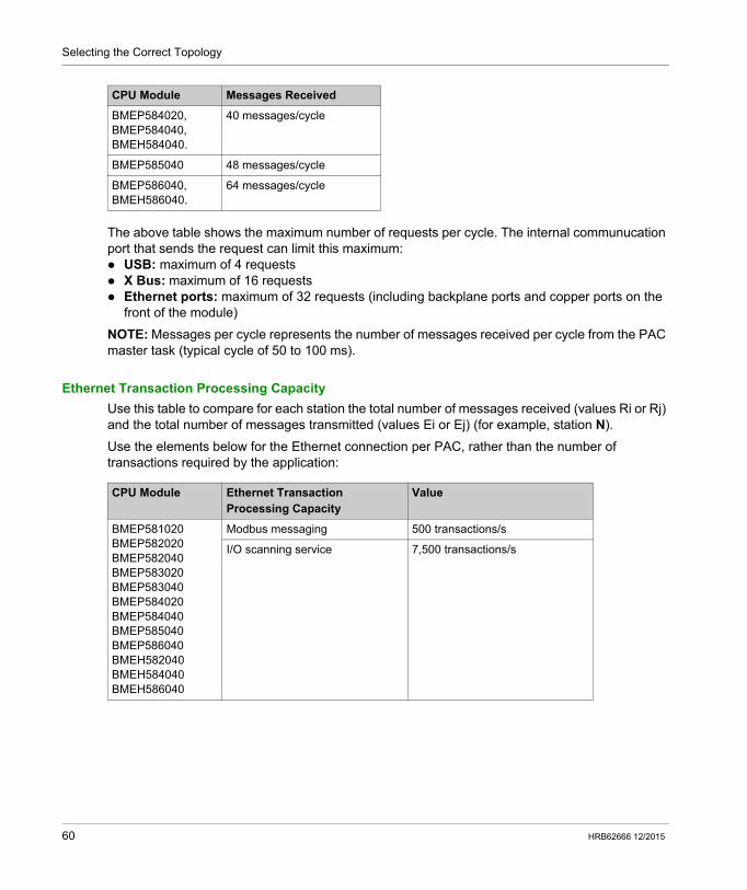
Selecting the Correct Topology
The above table shows the maximum number of requests per cycle. The internal communucation port that sends the request can limit this maximum: USB: maximum of 4 requests X Bus: maximum of 16 requests Ethernet ports: maximum of 32 requests (including backplane ports and copper ports on the
front of the module)
NOTE: Messages per cycle represents the number of messages received per cycle from the PAC master task (typical cycle of 50 to 100 ms).
Ethernet Transaction Processing Capacity
Use this table to compare for each station the total number of messages received (values Ri or Rj) and the total number of messages transmitted (values Ei or Ej) (for example, station N).
Use the elements below for the Ethernet connection per PAC, rather than the number of transactions required by the application:
BMEP584020, BMEP584040, BMEH584040.
40 messages/cycle
BMEP585040 48 messages/cycle
BMEP586040, BMEH586040.
64 messages/cycle
CPU Module Messages Received
CPU Module Ethernet Transaction Processing Capacity
Value
BMEP581020BMEP582020BMEP582040BMEP583020BMEP583040BMEP584020BMEP584040BMEP585040BMEP586040BMEH582040BMEH584040BMEH586040
Modbus messaging 500 transactions/s
I/O scanning service 7,500 transactions/s
60 HRB62666 12/2015
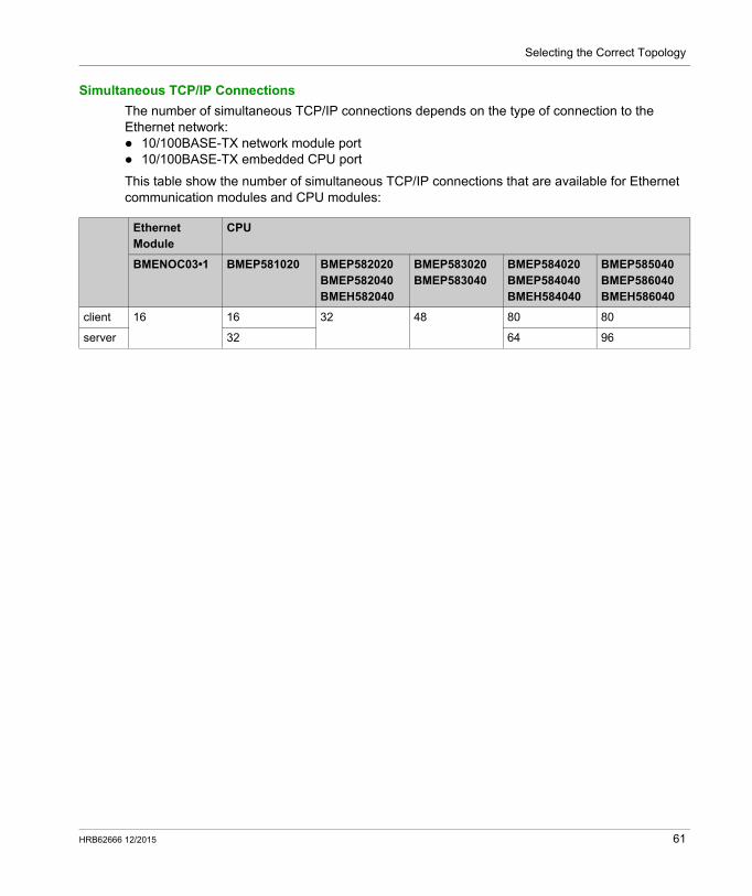
Selecting the Correct Topology
Simultaneous TCP/IP Connections
The number of simultaneous TCP/IP connections depends on the type of connection to the Ethernet network: 10/100BASE-TX network module port 10/100BASE-TX embedded CPU port
This table show the number of simultaneous TCP/IP connections that are available for Ethernet communication modules and CPU modules:
Ethernet Module
CPU
BMENOC03•1 BMEP581020 BMEP582020BMEP582040BMEH582040
BMEP583020BMEP583040
BMEP584020BMEP584040BMEH584040
BMEP585040BMEP586040BMEH586040
client 16 16 32 48 80 80
server 32 64 96
HRB62666 12/2015 61
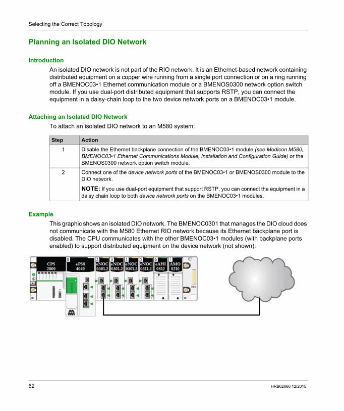
Selecting the Correct Topology
Planning an Isolated DIO Network
Introduction
An isolated DIO network is not part of the RIO network. It is an Ethernet-based network containing distributed equipment on a copper wire running from a single port connection or on a ring running off a BMENOC03•1 Ethernet communication module or a BMENOS0300 network option switch module. If you use dual-port distributed equipment that supports RSTP, you can connect the equipment in a daisy-chain loop to the two device network ports on a BMENOC03•1 module.
Attaching an Isolated DIO Network
To attach an isolated DIO network to an M580 system:
Example
This graphic shows an isolated DIO network. The BMENOC0301 that manages the DIO cloud does not communicate with the M580 Ethernet RIO network because its Ethernet backplane port is disabled. The CPU communicates with the other BMENOC03•1 modules (with backplane ports enabled) to support distributed equipment on the device network (not shown):
Step Action
1 Disable the Ethernet backplane connection of the BMENOC03•1 module (see Modicon M580, BMENOC03•1 Ethernet Communications Module, Installation and Configuration Guide) or the BMENOS0300 network option switch module.
2 Connect one of the device network ports of the BMENOC03•1 or BMENOS0300 module to the DIO network.
NOTE: If you use dual-port equipment that support RSTP, you can connect the equipment in a daisy chain loop to both device network ports on the BMENOC03•1 modules.
62 HRB62666 12/2015
Selecting the Correct Topology
Adding an Independent DIO Network
Introduction
Add an independent DIO network if you have existing distributed equipment — which you may not want to reconfigure — to the M580 system for the purpose of communicating with the control network.
An independent DIO network is not part of the Ethernet RIO network, but it does communicate with the control network.
An independent DIO network is an Ethernet-based network that includes distributed equipment on a copper wire that runs from a single port connection. If you use dual-port equipment that supports RSTP, you can connect the equipment in a daisy chain loop to the device network ports on the BMENOC03•1 Ethernet communication module.
Considerations: There is no backplane connection to the RIO network. A BMENOC03•1 Ethernet communication module communicates with another BMENOC03•1
module on the local rack to support communication with the M580 control network only. The Ethernet backplane ports on these modules are disabled so that they do not communicate with the CPU and the RIO network through the backplane.
HRB62666 12/2015 63
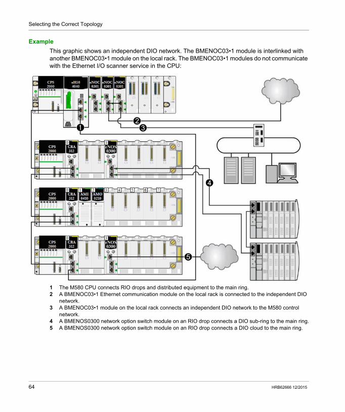
Selecting the Correct Topology
Example
This graphic shows an independent DIO network. The BMENOC03•1 module is interlinked with another BMENOC03•1 module on the local rack. The BMENOC03•1 modules do not communicate with the Ethernet I/O scanner service in the CPU:
1 The M580 CPU connects RIO drops and distributed equipment to the main ring.2 A BMENOC03•1 Ethernet communication module on the local rack is connected to the independent DIO
network.3 A BMENOC03•1 module on the local rack connects an independent DIO network to the M580 control
network.4 A BMENOS0300 network option switch module on an RIO drop connects a DIO sub-ring to the main ring.5 A BMENOS0300 network option switch module on an RIO drop connects a DIO cloud to the main ring.
64 HRB62666 12/2015
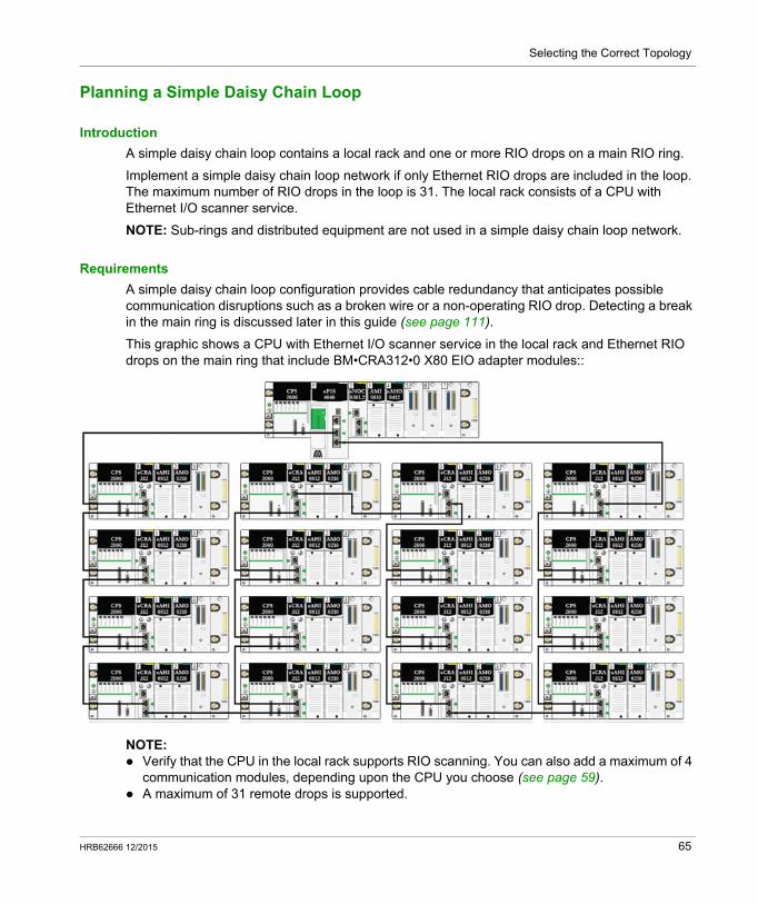
Selecting the Correct Topology
Planning a Simple Daisy Chain Loop
Introduction
A simple daisy chain loop contains a local rack and one or more RIO drops on a main RIO ring.
Implement a simple daisy chain loop network if only Ethernet RIO drops are included in the loop. The maximum number of RIO drops in the loop is 31. The local rack consists of a CPU with Ethernet I/O scanner service.
NOTE: Sub-rings and distributed equipment are not used in a simple daisy chain loop network.
Requirements
A simple daisy chain loop configuration provides cable redundancy that anticipates possible communication disruptions such as a broken wire or a non-operating RIO drop. Detecting a break in the main ring is discussed later in this guide (see page 111).
This graphic shows a CPU with Ethernet I/O scanner service in the local rack and Ethernet RIO drops on the main ring that include BM•CRA312•0 X80 EIO adapter modules::
NOTE: Verify that the CPU in the local rack supports RIO scanning. You can also add a maximum of 4
communication modules, depending upon the CPU you choose (see page 59). A maximum of 31 remote drops is supported.
HRB62666 12/2015 65
Selecting the Correct Topology
Only copper cable can be used, so there is a maximum distance of 100 m between any 2 consecutive RIO modules on the main ring. If you want to extend the distance beyond 100 m, use BMXNRP020• fiber converter modules (see page 75) to convert the copper cable to fiber.
If you connect a DIO cloud to the CPU on the local rack, the cloud is not part of the simple daisy-chain loop. The CPU services the control logic for the DIO cloud only after it has completed the logic scan for the RIO.
Planning a Simple Daisy Chain Loop
Follow the steps below to plan a simple daisy chain loop network. Configuration procedures are discussed in the respective Modicon M580 Ethernet communication/adapter module user guide.
NOTE: CPUs and eX80 EIO adapter modules do not have fiber ports. Therefore, the maximum distance
between the CPU and the first drop and between any two contiguous drops is less than 100 m, using shielded twisted 4-pair CAT5e or greater (10/100 Mbps) cable. (Do not use twisted 2-pair CAT5e or CAT6 cables.) If you want to extend the distance beyond 100 m, use DRSs (see Modicon M580, System Planning Guide for, Complex Topologies) or BMX NRP 020• (see page 75) fiber converter modules to convert the copper cable to fiber.
The Ethernet ports are clearly labeled on both the CPU with Ethernet I/O scanner service and the BM•CRA312•0 X80 EIO adapter module. If you connect these modules to the wrong ports, system performance will be affected.
Step Action
1 Plan the local rack (including the M580 CPU with Ethernet I/O scanner service and the power supply module.
2 Plan the Ethernet RIO drops. (Each drop includes a BM•CRA312•0 X80 EIO adapter module.)
3 Select a CPU that supports RIO and configure the Ethernet I/O scanner service for RIO.
4 Connect the Device Network port on the CPU to an Ethernet port on the adapter module at one of the drops. This completes the loop. Do not use the Service port or ETH 1 port on the CPU for this connection.
66 HRB62666 12/2015
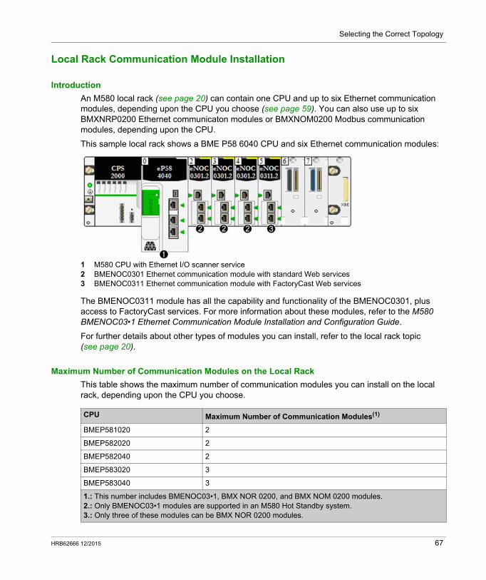
Selecting the Correct Topology
Local Rack Communication Module Installation
Introduction
An M580 local rack (see page 20) can contain one CPU and up to six Ethernet communication modules, depending upon the CPU you choose (see page 59). You can also use up to six BMXNRP0200 Ethernet communicaton modules or BMXNOM0200 Modbus communication modules, depending upon the CPU.
This sample local rack shows a BME P58 6040 CPU and six Ethernet communication modules:
1 M580 CPU with Ethernet I/O scanner service2 BMENOC0301 Ethernet communication module with standard Web services3 BMENOC0311 Ethernet communication module with FactoryCast Web services
The BMENOC0311 module has all the capability and functionality of the BMENOC0301, plus access to FactoryCast services. For more information about these modules, refer to the M580 BMENOC03•1 Ethernet Communication Module Installation and Configuration Guide.
For further details about other types of modules you can install, refer to the local rack topic (see page 20).
Maximum Number of Communication Modules on the Local Rack
This table shows the maximum number of communication modules you can install on the local rack, depending upon the CPU you choose.
CPU Maximum Number of Communication Modules(1)
BMEP581020 2
BMEP582020 2
BMEP582040 2
BMEP583020 3
BMEP583040 3
1.: This number includes BMENOC03•1, BMX NOR 0200, and BMX NOM 0200 modules.2.: Only BMENOC03•1 modules are supported in an M580 Hot Standby system.3.: Only three of these modules can be BMX NOR 0200 modules.
HRB62666 12/2015 67
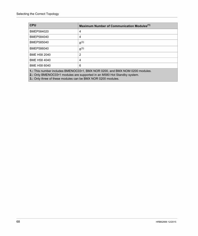
Selecting the Correct Topology
BMEP584020 4
BMEP584040 4
BMEP585040 8(3)
BMEP586040 8(3)
BME H58 2040 2
BME H58 4040 4
BME H58 6040 6
CPU Maximum Number of Communication Modules(1)
1.: This number includes BMENOC03•1, BMX NOR 0200, and BMX NOM 0200 modules.2.: Only BMENOC03•1 modules are supported in an M580 Hot Standby system.3.: Only three of these modules can be BMX NOR 0200 modules.
68 HRB62666 12/2015
Selecting the Correct Topology
Using Premium Racks in an M580 System
Introduction
An M580 system allows TSX RKY •EX Premium extended local racks. Using Premium racks in an M580 system allows you to preserve cabling in an existing configuration.
Premium rack compatibility:
NOTE: Only TSX RKY ••EX(C) racks are allowed in an M580 system. TSX RKY ••E racks are not compatible.
NOTE: Refer to the Premium hardware user guide for detailed rack information (see Premium and Atrium using Unity Pro, Processors, racks and power supply modules, Implementation manual).
Installing Premium Racks
The following steps provide an overview of how to install Premium racks in an M580 system.
NOTE: Use proper extender modules and bus terminators on each rack.
Main Local Rack
Extended Local Rack
Main Remote Rack
Extended Remote Rack
TSX RKY ••EX(C) Premium — X — —
X: allowed —: not allowed
Step Action
1 Install an M580 CPU on the main local rack.
2 Connect a Modicon X80 extended rack to the main local rack via X Bus extension cable.
NOTE: The maximum X Bus cable length between the M580 main local rack and the Modicon X80 extended local rack is 30 m (98 ft).
3 Connect a TSX RKY •EX Premium rack to the Modicon X80 extended local rack via X Bus extension cable.
4 If desired, connect a Premium extended rack to the Premium main rack via X Bus extension cable.
NOTE: The maximum X Bus cable length between the M580 main local rack and the Premium extended local rack is 100 m (328 ft).
HRB62666 12/2015 69
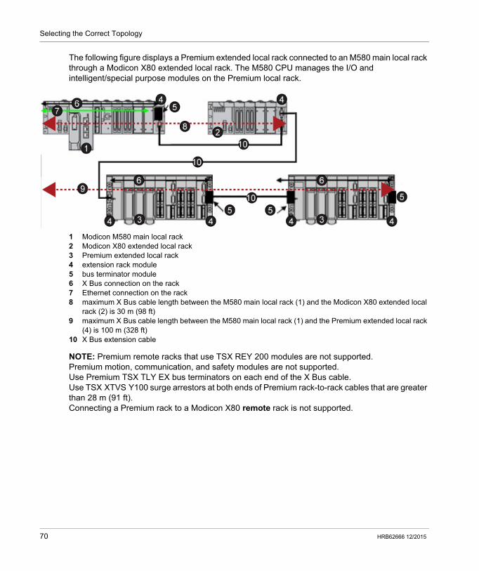
Selecting the Correct Topology
The following figure displays a Premium extended local rack connected to an M580 main local rack through a Modicon X80 extended local rack. The M580 CPU manages the I/O and intelligent/special purpose modules on the Premium local rack.
1 Modicon M580 main local rack2 Modicon X80 extended local rack3 Premium extended local rack4 extension rack module5 bus terminator module6 X Bus connection on the rack7 Ethernet connection on the rack8 maximum X Bus cable length between the M580 main local rack (1) and the Modicon X80 extended local
rack (2) is 30 m (98 ft)9 maximum X Bus cable length between the M580 main local rack (1) and the Premium extended local rack
(4) is 100 m (328 ft)10 X Bus extension cable
NOTE: Premium remote racks that use TSX REY 200 modules are not supported.Premium motion, communication, and safety modules are not supported.Use Premium TSX TLY EX bus terminators on each end of the X Bus cable.Use TSX XTVS Y100 surge arrestors at both ends of Premium rack-to-rack cables that are greater than 28 m (91 ft).Connecting a Premium rack to a Modicon X80 remote rack is not supported.
70 HRB62666 12/2015
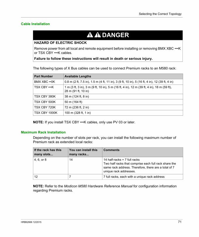
Selecting the Correct Topology
Cable Installation
The following types of X Bus cables can be used to connect Premium racks to an M580 rack:
NOTE: If you install TSX CBY •••K cables, only use PV 03 or later.
Maximum Rack Installation
Depending on the number of slots per rack, you can install the following maximum number of Premium rack as extended local racks:
NOTE: Refer to the Modicon M580 Hardware Reference Manual for configuration information regarding Premium racks.
DANGERHAZARD OF ELECTRIC SHOCK
Remove power from all local and remote equipment before installing or removing BMX XBC •••K or TSX CBY •••K cables.
Failure to follow these instructions will result in death or serious injury.
Part Number Available Lengths
BMX XBC ••0K 0.8 m (2 ft, 7.5 in), 1.5 m (4 ft, 11 in), 3 (9 ft, 10 in), 5 (16 ft, 4 in), 12 (39 ft, 4 in)
TSX CBY •••K 1 m (3 ft, 3 in), 3 m (9 ft, 10 in), 5 m (16 ft, 4 in), 12 m (39 ft, 4 in), 18 m (59 ft), 28 m (91 ft, 10 in)
TSX CBY 380K 38 m (124 ft, 8 in)
TSX CBY 500K 50 m (164 ft)
TSX CBY 720K 72 m (236 ft, 2 in)
TSX CBY 1000K 100 m (328 ft, 1 in)
If the rack has this many slots...
You can install this many racks...
Comments
4, 6, or 8 14 14 half-racks = 7 full racksTwo half racks that comprise each full rack share the same rack address. Therefore, there are a total of 7 unique rack addresses.
12 7 7 full racks, each with a unique rack address
HRB62666 12/2015 71
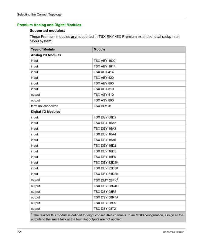
Selecting the Correct Topology
Premium Analog and Digital Modules
Supported modules:
These Premium modules are supported in TSX RKY •EX Premium extended local racks in an M580 system:
Type of Module Module
Analog I/O Modules
input TSX AEY 1600
input TSX AEY 1614
input TSX AEY 414
input TSX AEY 420
input TSX AEY 800
input TSX AEY 810
output TSX ASY 410
output TSX ASY 800
terminal connector TSX BLY 01
Digital I/O Modules
input TSX DEY 08D2
input TSX DEY 16A2
input TSX DEY 16A3
input TSX DEY 16A4
input TSX DEY 16A5
input TSX DEY 16D2
input TSX DEY 16D3
input TSX DEY 16FK
input TSX DEY 32D2K
input TSX DEY 32D3K
input TSX DEY 64D2K
output TSX DMY 28FK1
output TSX DSY 08R4D
output TSX DSY 08R5
output TSX DSY 08R5A
output TSX DSY 08S5
output TSX DSY 08T2
1 The task for this module is defined for eight consecutive channels. In an M580 configuration, assign all the outputs to the same task or the four last outputs are not applied.
72 HRB62666 12/2015
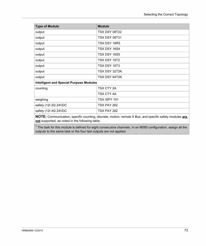
Selecting the Correct Topology
output TSX DSY 08T22
output TSX DSY 08T31
output TSX DSY 16R5
output TSX DSY 16S4
output TSX DSY 16S5
output TSX DSY 16T2
output TSX DSY 16T3
output TSX DSY 32T2K
output TSX DSY 64T2K
Intelligent and Special Purpose Modules
counting TSX CTY 2A
TSX CTY 4A
weighing TSX ISPY 101
safety (12I 2Q 24VDC TSX PAY 262
safety (12I 4Q 24VDC TSX PAY 282
NOTE: Communication, specific counting, discrete, motion, remote X Bus, and specific safety modules are not supported, as noted in the following table.
Type of Module Module
1 The task for this module is defined for eight consecutive channels. In an M580 configuration, assign all the outputs to the same task or the four last outputs are not applied.
HRB62666 12/2015 73
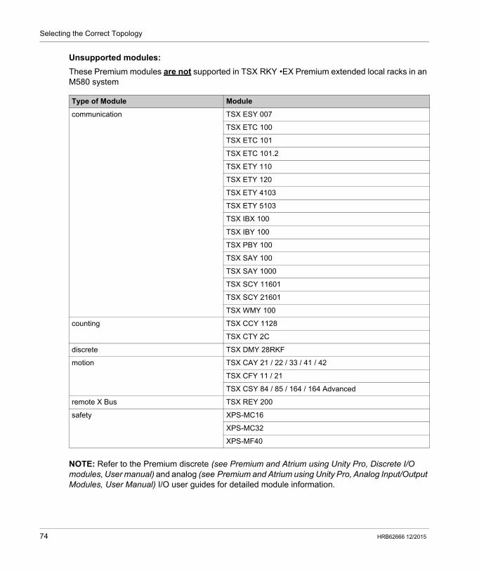
Selecting the Correct Topology
Unsupported modules:
These Premium modules are not supported in TSX RKY •EX Premium extended local racks in an M580 system
NOTE: Refer to the Premium discrete (see Premium and Atrium using Unity Pro, Discrete I/O modules, User manual) and analog (see Premium and Atrium using Unity Pro, Analog Input/Output Modules, User Manual) I/O user guides for detailed module information.
Type of Module Module
communication TSX ESY 007
TSX ETC 100
TSX ETC 101
TSX ETC 101.2
TSX ETY 110
TSX ETY 120
TSX ETY 4103
TSX ETY 5103
TSX IBX 100
TSX IBY 100
TSX PBY 100
TSX SAY 100
TSX SAY 1000
TSX SCY 11601
TSX SCY 21601
TSX WMY 100
counting TSX CCY 1128
TSX CTY 2C
discrete TSX DMY 28RKF
motion TSX CAY 21 / 22 / 33 / 41 / 42
TSX CFY 11 / 21
TSX CSY 84 / 85 / 164 / 164 Advanced
remote X Bus TSX REY 200
safety XPS-MC16
XPS-MC32
XPS-MF40
74 HRB62666 12/2015
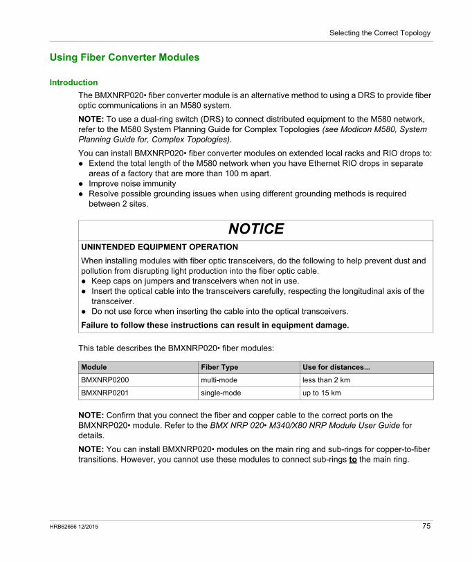
Selecting the Correct Topology
Using Fiber Converter Modules
Introduction
The BMXNRP020• fiber converter module is an alternative method to using a DRS to provide fiber optic communications in an M580 system.
NOTE: To use a dual-ring switch (DRS) to connect distributed equipment to the M580 network, refer to the M580 System Planning Guide for Complex Topologies (see Modicon M580, System Planning Guide for, Complex Topologies).
You can install BMXNRP020• fiber converter modules on extended local racks and RIO drops to: Extend the total length of the M580 network when you have Ethernet RIO drops in separate
areas of a factory that are more than 100 m apart. Improve noise immunity Resolve possible grounding issues when using different grounding methods is required
between 2 sites.
This table describes the BMXNRP020• fiber modules:
NOTE: Confirm that you connect the fiber and copper cable to the correct ports on the BMXNRP020• module. Refer to the BMX NRP 020• M340/X80 NRP Module User Guide for details.
NOTE: You can install BMXNRP020• modules on the main ring and sub-rings for copper-to-fiber transitions. However, you cannot use these modules to connect sub-rings to the main ring.
NOTICEUNINTENDED EQUIPMENT OPERATION
When installing modules with fiber optic transceivers, do the following to help prevent dust and pollution from disrupting light production into the fiber optic cable. Keep caps on jumpers and transceivers when not in use. Insert the optical cable into the transceivers carefully, respecting the longitudinal axis of the
transceiver. Do not use force when inserting the cable into the optical transceivers.
Failure to follow these instructions can result in equipment damage.
Module Fiber Type Use for distances...
BMXNRP0200 multi-mode less than 2 km
BMXNRP0201 single-mode up to 15 km
HRB62666 12/2015 75
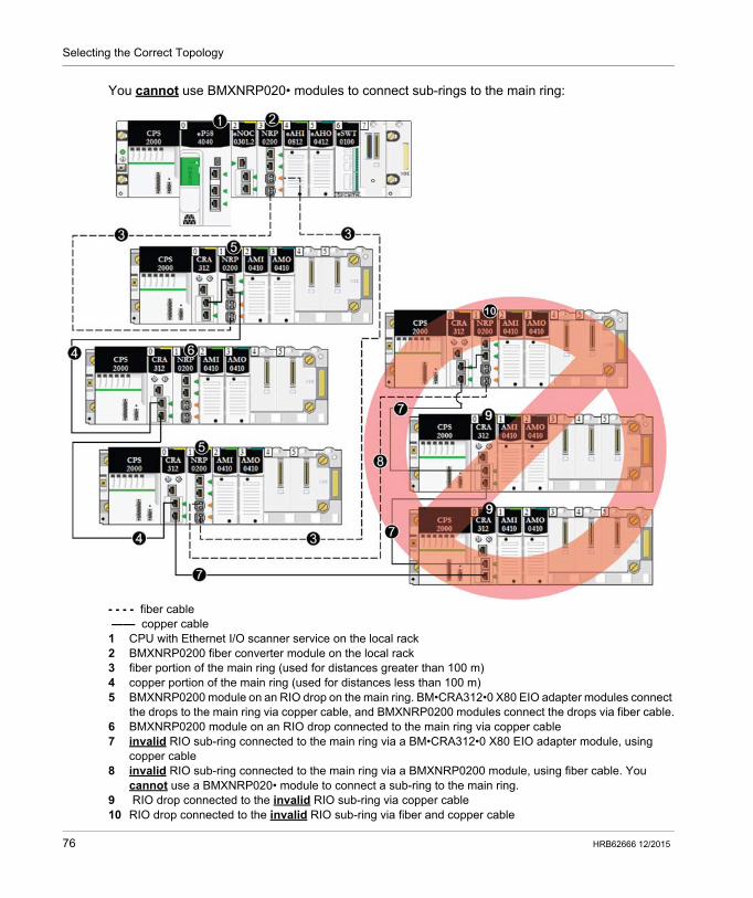
Selecting the Correct Topology
You cannot use BMXNRP020• modules to connect sub-rings to the main ring:
- - - - fiber cable —— copper cable1 CPU with Ethernet I/O scanner service on the local rack2 BMXNRP0200 fiber converter module on the local rack3 fiber portion of the main ring (used for distances greater than 100 m)4 copper portion of the main ring (used for distances less than 100 m)5 BMXNRP0200 module on an RIO drop on the main ring. BM•CRA312•0 X80 EIO adapter modules connect
the drops to the main ring via copper cable, and BMXNRP0200 modules connect the drops via fiber cable.6 BMXNRP0200 module on an RIO drop connected to the main ring via copper cable7 invalid RIO sub-ring connected to the main ring via a BM•CRA312•0 X80 EIO adapter module, using
copper cable8 invalid RIO sub-ring connected to the main ring via a BMXNRP0200 module, using fiber cable. You
cannot use a BMXNRP020• module to connect a sub-ring to the main ring.9 RIO drop connected to the invalid RIO sub-ring via copper cable10 RIO drop connected to the invalid RIO sub-ring via fiber and copper cable
76 HRB62666 12/2015
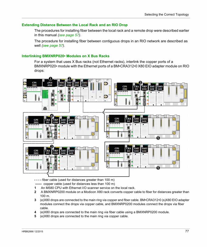
Selecting the Correct Topology
Extending Distance Between the Local Rack and an RIO Drop
The procedures for installing fiber between the local rack and a remote drop were described earlier in this manual (see page 57).
The procedure for installing fiber between contiguous drops in an RIO network are described as well (see page 57).
Interlinking BMXNRP020• Modules on X Bus Racks
For a system that uses X Bus racks (not Ethernet racks), interlink the copper ports of a BMXNRP020• module with the Ethernet ports of a BM•CRA312•0 X80 EIO adapter module on RIO drops:
- - - - fiber cable (used for distances greater than 100 m) —— copper cable (used for distances less than 100 m)1 An M580 CPU with Ethernet I/O scanner service on the local rack.2 A BMXNRP0200 module on a Modicon X80 rack converts copper cable to fiber for distances greater than
100 m.3 (e)X80 drops are connected to the main ring via copper and fiber cable. BM•CRA312•0 (s)X80 EIO adapter
modules connect the drops via copper cable, and BMXNRP0200 modules connect the drops via fiber cable.
4 (e)X80 drops are connected to the main ring via fiber cable using a BMXNRP0200 module.5 (e)X80 drops are connected to the main ring via copper cable.
HRB62666 12/2015 77

Selecting the Correct Topology
Diagnosing Fiber Converter Modules
To diagnose the BMXNRP020• fiber converter modules, refer to the BMX NRP 0200/0201 M340/X80 Fiber Converter Module User Guide.
78 HRB62666 12/2015
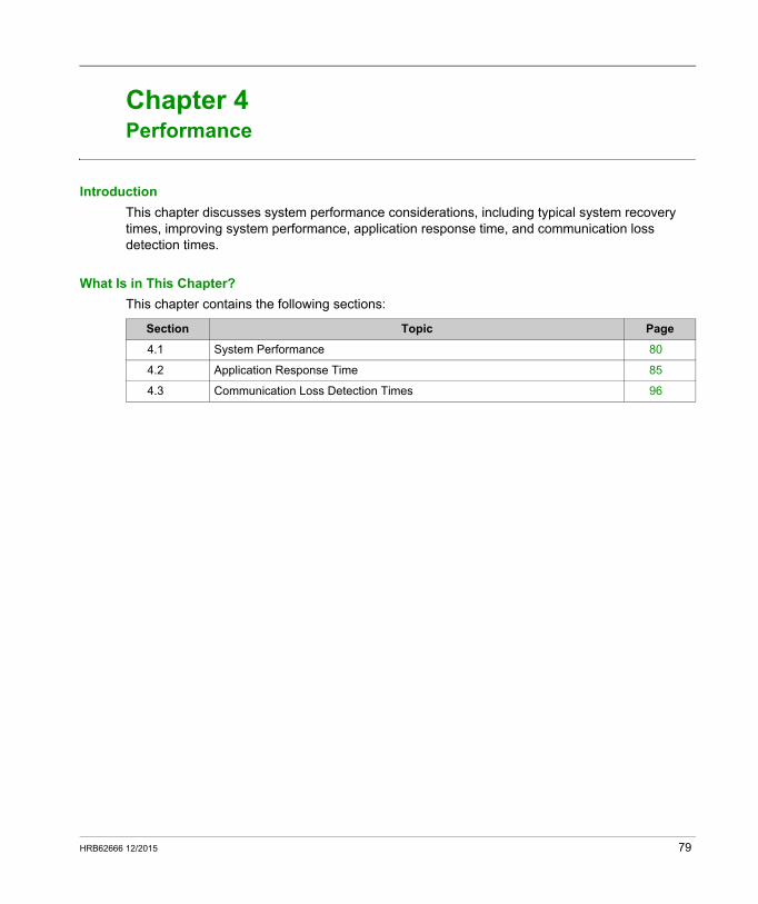
Modicon M580 Standalone
Performance
HRB62666 12/2015
Performance
Chapter 4Performance
Introduction
This chapter discusses system performance considerations, including typical system recovery times, improving system performance, application response time, and communication loss detection times.
What Is in This Chapter?
This chapter contains the following sections:
Section Topic Page
4.1 System Performance 80
4.2 Application Response Time 85
4.3 Communication Loss Detection Times 96
HRB62666 12/2015 79
Performance
System Performance
Section 4.1System Performance
Introduction
Creating a deterministic RIO system requires the use of network components and designs that support switched Ethernet communication including: full duplex transmissions 100 Mbps transmission speed QoS prioritization of RIO packets
This chapter introduces you to devices that meet these performance considerations. It also presents typical system recovery times and describes methods to help improve system performance.
What Is in This Section?
This section contains the following topics:
Topic Page
System Performance 81
System Throughput Considerations 82
Calculating the Minimum MAST Cycle Time 84
80 HRB62666 12/2015
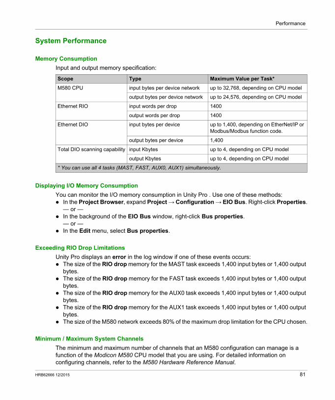
Performance
System Performance
Memory Consumption
Input and output memory specification:
Displaying I/O Memory Consumption
You can monitor the I/O memory consumption in Unity Pro . Use one of these methods: In the Project Browser, expand Project → Configuration → EIO Bus. Right-click Properties.
— or — In the background of the EIO Bus window, right-click Bus properties.
— or — In the Edit menu, select Bus properties.
Exceeding RIO Drop Limitations
Unity Pro displays an error in the log window if one of these events occurs: The size of the RIO drop memory for the MAST task exceeds 1,400 input bytes or 1,400 output
bytes. The size of the RIO drop memory for the FAST task exceeds 1,400 input bytes or 1,400 output
bytes. The size of the RIO drop memory for the AUX0 task exceeds 1,400 input bytes or 1,400 output
bytes. The size of the RIO drop memory for the AUX1 task exceeds 1,400 input bytes or 1,400 output
bytes. The size of the M580 network exceeds 80% of the maximum drop limitation for the CPU chosen.
Minimum / Maximum System Channels
The minimum and maximum number of channels that an M580 configuration can manage is a function of the Modicon M580 CPU model that you are using. For detailed information on configuring channels, refer to the M580 Hardware Reference Manual.
Scope Type Maximum Value per Task*
M580 CPU input bytes per device network up to 32,768, depending on CPU model
output bytes per device network up to 24,576, depending on CPU model
Ethernet RIO input words per drop 1400
output words per drop 1400
Ethernet DIO input bytes per device up to 1,400, depending on EtherNet/IP or Modbus/Modbus function code.
output bytes per device 1,400
Total DIO scanning capability input Kbytes up to 4, depending on CPU model
output Kbytes up to 4, depending on CPU model
* You can use all 4 tasks (MAST, FAST, AUX0, AUX1) simultaneously.
HRB62666 12/2015 81
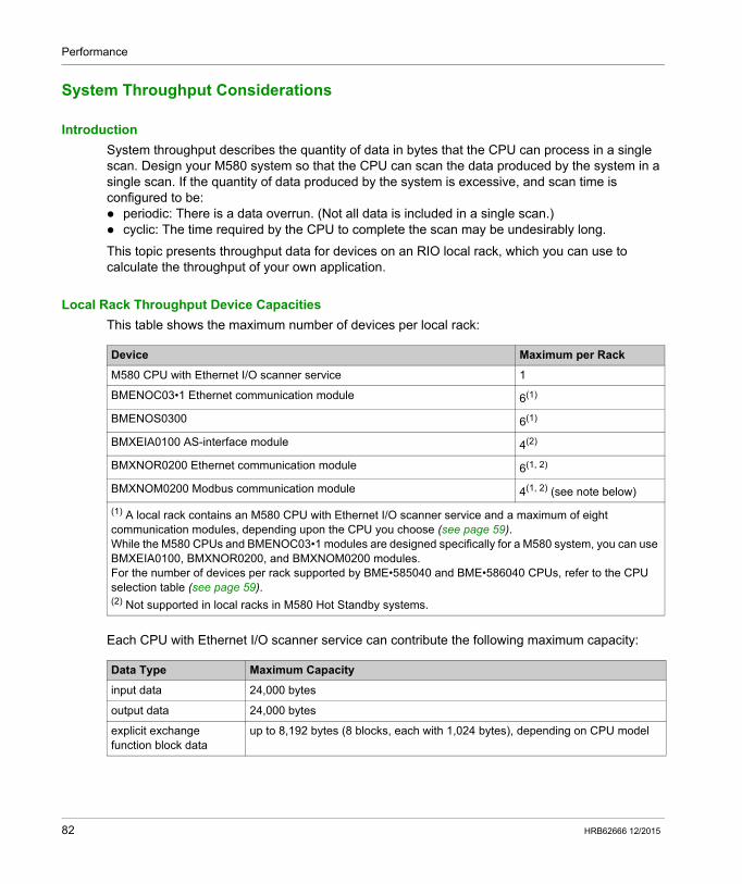
Performance
System Throughput Considerations
Introduction
System throughput describes the quantity of data in bytes that the CPU can process in a single scan. Design your M580 system so that the CPU can scan the data produced by the system in a single scan. If the quantity of data produced by the system is excessive, and scan time is configured to be: periodic: There is a data overrun. (Not all data is included in a single scan.) cyclic: The time required by the CPU to complete the scan may be undesirably long.
This topic presents throughput data for devices on an RIO local rack, which you can use to calculate the throughput of your own application.
Local Rack Throughput Device Capacities
This table shows the maximum number of devices per local rack:
Each CPU with Ethernet I/O scanner service can contribute the following maximum capacity:
Device Maximum per Rack
M580 CPU with Ethernet I/O scanner service 1
BMENOC03•1 Ethernet communication module 6(1)
BMENOS0300 6(1)
BMXEIA0100 AS-interface module 4(2)
BMXNOR0200 Ethernet communication module 6(1, 2)
BMXNOM0200 Modbus communication module 4(1, 2) (see note below)
(1) A local rack contains an M580 CPU with Ethernet I/O scanner service and a maximum of eight communication modules, depending upon the CPU you choose (see page 59).While the M580 CPUs and BMENOC03•1 modules are designed specifically for a M580 system, you can use BMXEIA0100, BMXNOR0200, and BMXNOM0200 modules.For the number of devices per rack supported by BME•585040 and BME•586040 CPUs, refer to the CPU selection table (see page 59).(2) Not supported in local racks in M580 Hot Standby systems.
Data Type Maximum Capacity
input data 24,000 bytes
output data 24,000 bytes
explicit exchange function block data
up to 8,192 bytes (8 blocks, each with 1,024 bytes), depending on CPU model
82 HRB62666 12/2015
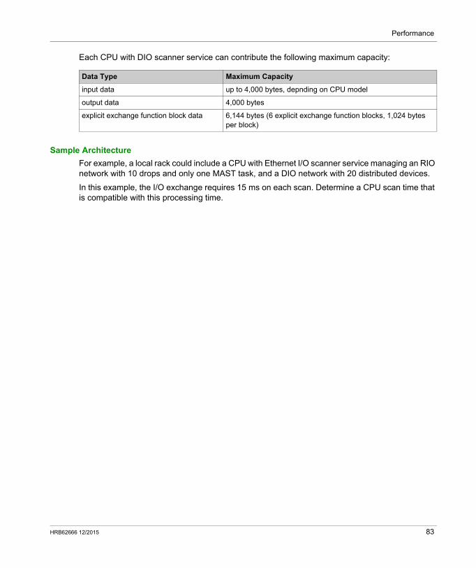
Performance
Each CPU with DIO scanner service can contribute the following maximum capacity:
Sample Architecture
For example, a local rack could include a CPU with Ethernet I/O scanner service managing an RIO network with 10 drops and only one MAST task, and a DIO network with 20 distributed devices.
In this example, the I/O exchange requires 15 ms on each scan. Determine a CPU scan time that is compatible with this processing time.
Data Type Maximum Capacity
input data up to 4,000 bytes, depnding on CPU model
output data 4,000 bytes
explicit exchange function block data 6,144 bytes (6 explicit exchange function blocks, 1,024 bytes per block)
HRB62666 12/2015 83
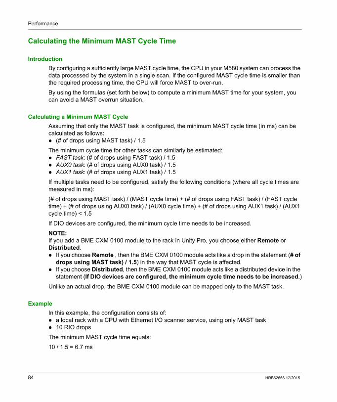
Performance
Calculating the Minimum MAST Cycle Time
Introduction
By configuring a sufficiently large MAST cycle time, the CPU in your M580 system can process the data processed by the system in a single scan. If the configured MAST cycle time is smaller than the required processing time, the CPU will force MAST to over-run.
By using the formulas (set forth below) to compute a minimum MAST time for your system, you can avoid a MAST overrun situation.
Calculating a Minimum MAST Cycle
Assuming that only the MAST task is configured, the minimum MAST cycle time (in ms) can be calculated as follows: (# of drops using MAST task) / 1.5
The minimum cycle time for other tasks can similarly be estimated: FAST task: (# of drops using FAST task) / 1.5 AUX0 task: (# of drops using AUX0 task) / 1.5 AUX1 task: (# of drops using AUX1 task) / 1.5
If multiple tasks need to be configured, satisfy the following conditions (where all cycle times are measured in ms):
(# of drops using MAST task) / (MAST cycle time) + (# of drops using FAST task) / (FAST cycle time) + (# of drops using AUX0 task) / (AUX0 cycle time) + (# of drops using AUX1 task) / (AUX1 cycle time) < 1.5
If DIO devices are configured, the minimum cycle time needs to be increased.
NOTE: If you add a BME CXM 0100 module to the rack in Unity Pro, you choose either Remote or Distributed. If you choose Remote , then the BME CXM 0100 module acts like a drop in the statement (# of
drops using MAST task) / 1.5) in the way that MAST cycle is affected. If you choose Distributed, then the BME CXM 0100 module acts like a distributed device in the
statement (If DIO devices are configured, the minimum cycle time needs to be increased.)
Unlike an actual drop, the BME CXM 0100 module can be mapped only to the MAST task.
Example
In this example, the configuration consists of: a local rack with a CPU with Ethernet I/O scanner service, using only MAST task 10 RIO drops
The minimum MAST cycle time equals:
10 / 1.5 = 6.7 ms
84 HRB62666 12/2015
Performance
Application Response Time
Section 4.2Application Response Time
Introduction
Application response time (ART) is the time a CPU application takes to react to an input,starting when the input signal triggers a write command from the CPU and ending when the corresponding output module changes state.
What Is in This Section?
This section contains the following topics:
Topic Page
Simplified Presentation of Application Response Time 86
Application Response Time 89
Application Response Time Examples 92
Optimizing Application Response Time 94
HRB62666 12/2015 85
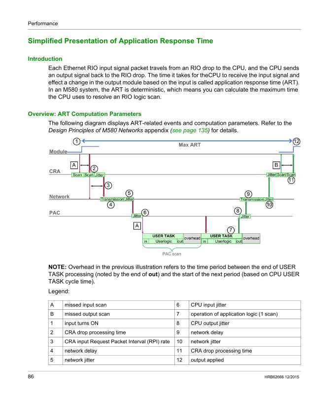
Performance
Simplified Presentation of Application Response Time
Introduction
Each Ethernet RIO input signal packet travels from an RIO drop to the CPU, and the CPU sends an output signal back to the RIO drop. The time it takes for theCPU to receive the input signal and effect a change in the output module based on the input is called application response time (ART). In an M580 system, the ART is deterministic, which means you can calculate the maximum time the CPU uses to resolve an RIO logic scan.
Overview: ART Computation Parameters
The following diagram displays ART-related events and computation parameters. Refer to the Design Principles of M580 Networks appendix (see page 135) for details.
NOTE: Overhead in the previous illustration refers to the time period between the end of USER TASK processing (noted by the end of out) and the start of the next period (based on CPU USER TASK cycle time).
Legend:
A missed input scan 6 CPU input jitter
B missed output scan 7 operation of application logic (1 scan)
1 input turns ON 8 CPU output jitter
2 CRA drop processing time 9 network delay
3 CRA input Request Packet Interval (RPI) rate 10 network jitter
4 network delay 11 CRA drop processing time
5 network jitter 12 output applied
86 HRB62666 12/2015
Performance
Quick Estimation of ART
To estimate the maximum ART based on the maximum number of RIO modules and distributed equipment for an application, sum these values: CRA->Scanner RPI 2 * CPU_Scan (for the task) 8.8 ms ( a constant value representing the maximum CRA processing time)
NOTE: Because the FAST task has highest priority, the ART for the FAST task is not impacted by other tasks.
ART considerations:
multitasking The above calculation is valid for each task. However, in a multitasking situation, the CPU_Scan time may be increased due to higher-priority tasks.If the MAST task is combined with the FAST task (multitasking), the CPU_Scan for the MAST task may be increased significantly. The result of multitasking can be a much longer ART for the MAST task.
Hot Standby Refer to the Modicon M580 Hot Standby System Planning Guide for Frequently Used Architectures to calculate ART for Hot Standby CPUs (see Modicon M580 Hot Standby, System Planning Guide for, Frequently Used Architectures).
broken cable If a cable break occurs or a cable is reconnected on the network, add an additional time period to the above ART calculation to allow for RSTP recovery. The additional time to be added equals: 50 ms + CRA->Scanner RPI.
HRB62666 12/2015 87
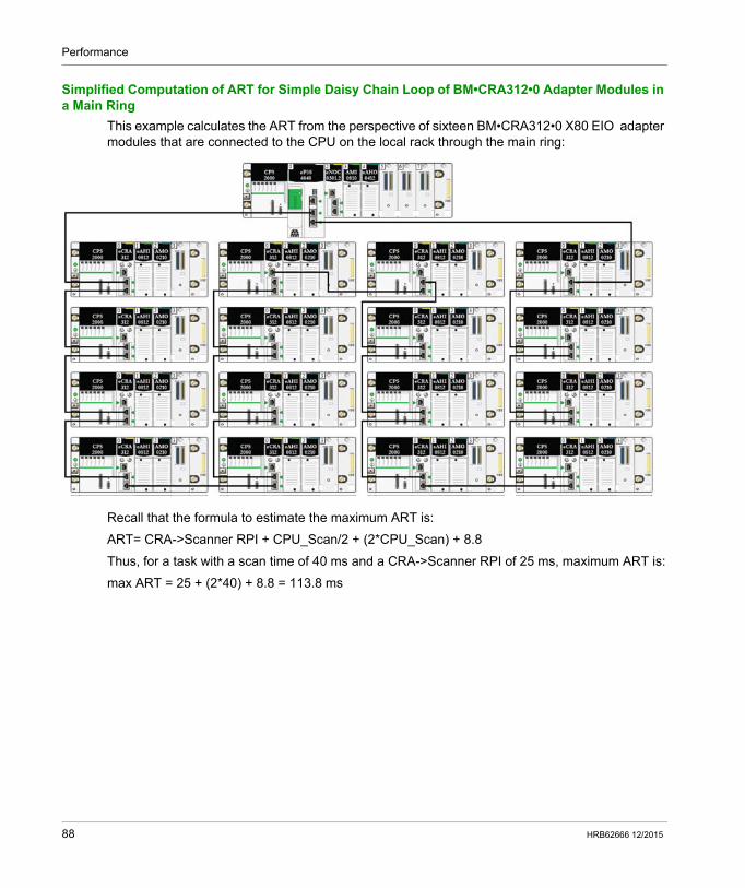
Performance
Simplified Computation of ART for Simple Daisy Chain Loop of BM•CRA312•0 Adapter Modules in a Main Ring
This example calculates the ART from the perspective of sixteen BM•CRA312•0 X80 EIO adapter modules that are connected to the CPU on the local rack through the main ring:
Recall that the formula to estimate the maximum ART is:
ART= CRA->Scanner RPI + CPU_Scan/2 + (2*CPU_Scan) + 8.8
Thus, for a task with a scan time of 40 ms and a CRA->Scanner RPI of 25 ms, maximum ART is:
max ART = 25 + (2*40) + 8.8 = 113.8 ms
88 HRB62666 12/2015
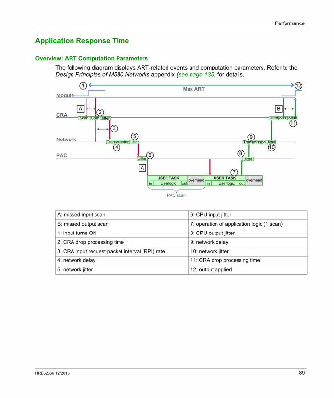
Performance
Application Response Time
Overview: ART Computation Parameters
The following diagram displays ART-related events and computation parameters. Refer to the Design Principles of M580 Networks appendix (see page 135) for details.
A: missed input scan 6: CPU input jitter
B: missed output scan 7: operation of application logic (1 scan)
1: input turns ON 8: CPU output jitter
2: CRA drop processing time 9: network delay
3: CRA input request packet interval (RPI) rate 10: network jitter
4: network delay 11: CRA drop processing time
5: network jitter 12: output applied
HRB62666 12/2015 89
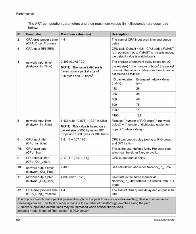
Performance
The ART computation parameters and their maximum values (in milliseconds) are described below:
ID Parameter Maximum value (ms) Description
2 CRA drop process time (CRA_Drop_Process)
4.4 The sum of CRA input scan time and queue delay
3 CRA input RPI (RPI) – CPU task. Default = 0.5 * CPU period if MAST is in periodic mode. If MAST is in cyclic mode, the default value is watchdog/4).
4 network input time2 (Network_In_Time)
2.496 (0.078 * 32)
NOTE: The value 2.496 ms is based upon a packet size of
800 bytes and 32 hops1.
The product of (network delay based on I/O
packet size) * (the number of hops1 the packet travels). The network delay component can be estimated as follows:
I/O packet size (bytes):
Estimated network delay (μs):
128 26
256 35
400 46
800 78
1200 110
1400 127
5 network input jitter (Network_In_Jitter)
6.436 ((30 * 0.078) + (32 * 0.128))
NOTE: This value is based on a packet size of 800 bytes for RIO drops and 1500 bytes for DIO traffic.
formula: ((number of RIO drops) * (network delay)) + ((number of distributed equipment
hops1) * network delay)
6 CPU input jitter (CPU_In_Jitter)
5.41 (1 + (.07 * 63)) CPU input queue delay (owing to RIO drops and DIO traffic)
7/8 CPU scan time (CPU_Scan)
– This is the user defined Unity Pro scan time, which can be either fixed or cyclic.
9 CPU output jitter (CPU_Out_Jitter)
2.17 (1 + (0.07 * 31)) CPU output queue delay.
10 network output time2 (Network_Out_Time)
2.496 See calculation above for Network_In_Time.
11 network output jitter (Network_Out_Jitter)
4.096 (32 * 0.128) Calculate in the same manner as Network_In_Jitter without I/O frames from RIO drops.
12 CRA drop process time (CRA_Drop_Process)
4.4 The sum of CRA queue delay and output scan time.
1. A hop is a switch that a packet passes through on the path from a source (transmitting) device to a destination (receiving) device. The total number of hops is the number of passthrough switches along the path.2. Network input and output times may be increased when optical fiber is used.increase = total length of fiber cables * 0.0034 ms/km
90 HRB62666 12/2015
Performance
Estimating ART
Using the parameters described in the preceding table, you can compute the maximum estimated ART based on the maximum number of RIO modules and distributed equipment for an application.
The maximum ART value is equal to the sum of values in the Maximum value column. Therefore, the ART calculation for a CPU scan time (CPU_Scan) of 50 ms and an RPI value of 25 ms looks like this:
4.4 + 25 + 2.496 + 6.436 + 5.41 + (2 * 50) + 2.17 + 2.496 + 4.096 + 4.4 = 156.904 ms ART
NOTE: If a cable break occurs or a cable is reconnected on the network, add an additional time period to the above ART calculation to allow for RSTP recovery. The additional time to be added equals: 50 ms + CPU_Scan/2.
HRB62666 12/2015 91
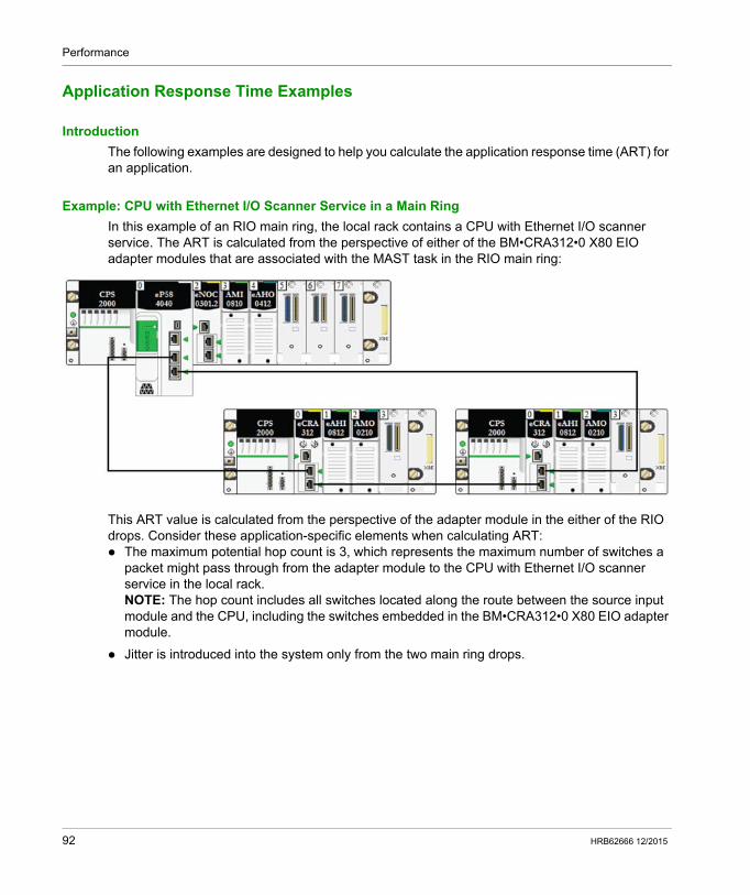
Performance
Application Response Time Examples
Introduction
The following examples are designed to help you calculate the application response time (ART) for an application.
Example: CPU with Ethernet I/O Scanner Service in a Main Ring
In this example of an RIO main ring, the local rack contains a CPU with Ethernet I/O scanner service. The ART is calculated from the perspective of either of the BM•CRA312•0 X80 EIO adapter modules that are associated with the MAST task in the RIO main ring:
This ART value is calculated from the perspective of the adapter module in the either of the RIO drops. Consider these application-specific elements when calculating ART: The maximum potential hop count is 3, which represents the maximum number of switches a
packet might pass through from the adapter module to the CPU with Ethernet I/O scanner service in the local rack.NOTE: The hop count includes all switches located along the route between the source input module and the CPU, including the switches embedded in the BM•CRA312•0 X80 EIO adapter module.
Jitter is introduced into the system only from the two main ring drops.
92 HRB62666 12/2015
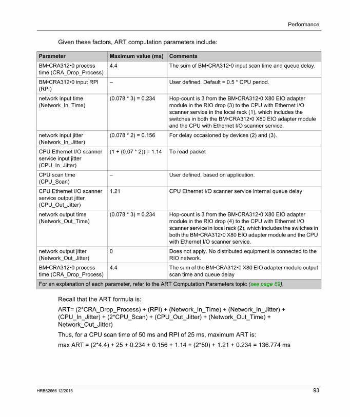
Performance
Given these factors, ART computation parameters include:
Recall that the ART formula is:
ART= (2*CRA_Drop_Process) + (RPI) + (Network_In_Time) + (Network_In_Jitter) + (CPU_In_Jitter) + (2*CPU_Scan) + (CPU_Out_Jitter) + (Network_Out_Time) + Network_Out_Jitter)
Thus, for a CPU scan time of 50 ms and RPI of 25 ms, maximum ART is:
max ART = (2*4.4) + 25 + 0.234 + 0.156 + 1.14 + (2*50) + 1.21 + 0.234 = 136.774 ms
Parameter Maximum value (ms) Comments
BM•CRA312•0 process time (CRA_Drop_Process)
4.4 The sum of BM•CRA312•0 input scan time and queue delay.
BM•CRA312•0 input RPI (RPI)
– User defined. Default = 0.5 * CPU period.
network input time (Network_In_Time)
(0.078 * 3) = 0.234 Hop-count is 3 from the BM•CRA312•0 X80 EIO adapter module in the RIO drop (3) to the CPU with Ethernet I/O scanner service in the local rack (1), which includes the switches in both the BM•CRA312•0 X80 EIO adapter module and the CPU with Ethernet I/O scanner service.
network input jitter (Network_In_Jitter)
(0.078 * 2) = 0.156 For delay occasioned by devices (2) and (3).
CPU Ethernet I/O scanner service input jitter (CPU_In_Jitter)
(1 + (0.07 * 2)) = 1.14 To read packet
CPU scan time (CPU_Scan)
– User defined, based on application.
CPU Ethernet I/O scanner service output jitter (CPU_Out_Jitter)
1.21 CPU Ethernet I/O scanner service internal queue delay
network output time (Network_Out_Time)
(0.078 * 3) = 0.234 Hop-count is 3 from the BM•CRA312•0 X80 EIO adapter module in the RIO drop (4) to the CPU with Ethernet I/O scanner service in local rack (2), which includes the switches in both the BM•CRA312•0 X80 EIO adapter module and the CPU with Ethernet I/O scanner service.
network output jitter (Network_Out_Jitter)
0 Does not apply. No distributed equipment is connected to the RIO network.
BM•CRA312•0 process time (CRA_Drop_Process)
4.4 The sum of the BM•CRA312•0 X80 EIO adapter module output scan time and queue delay
For an explanation of each parameter, refer to the ART Computation Parameters topic (see page 89).
HRB62666 12/2015 93
Performance
Optimizing Application Response Time
Overview
You can reduce the maximum application response time (ART) for your system, by employing these network design tips: use only the minimally required number of RIO drops (BM•CRA312•0 X80 EIO adapter
modules) use only the minimally required number of RIO input and output modules place the RIO drops with the fastest communications capacity nearest to the local rack
containing the CPU with Ethernet I/O scanner service
In addition, you can further reduce ART by using the FAST task in your Unity Pro logic.
NOTE: In an M580 Hot Standby (see Modicon M580 Hot Standby, System Planning Guide for, Frequently Used Architectures)system, plan your topology accordingly so the amount of data exchanged is reduced.
Reducing the Number of RIO Drops
When you reduce the number of RIO drops in your system, you also reduce: the number of hops that a packet passes through from an RIO drop to the CPU with Ethernet
I/O scanner service in the local rack the number of packets received by the CPU with Ethernet I/O scanner service
By reducing these values, you also reduce the following elements of ART: network input/output times network input/output jitter CPU with Ethernet I/O scanner service CPU scan time (the greatest savings)
Reducing the Number of Remote Input and Output Modules
When you reduce the number of RIO input and output modules, you also reduce the size of the packet, which in turn reduces the following elements of ART: network input/output time network input/output jitter BM•CRA312•0 module drop process time
Placing the Fastest RIO Drops Nearest to the Local Rack
When you place the fastest RIO drops nearest to the local rack, you reduce the number of hops that a packet passes through from the RIO drop to the local rack. You also reduce the following elements of ART: network input/output time network input/output jitter
94 HRB62666 12/2015
Performance
Using the FAST Task to Optimize ART
Using the FAST task can result in smaller ART because the I/O data associated with the FAST task can be executed at a higher priority. ART when using FAST task is not degraded because of the task’s priority.
NOTE: These efficiencies of the FAST task are not realized during end-of-scan delays.
The Unity Pro help pages further describe the multiple tasks (see Unity Pro, Program Languages and Structure, Reference Manual ).
Scan Type Period (ms) / Default Value
Watchdog (ms) / Default Value
Usage (I/O)
MAST1 cyclic2 or periodic 1...255 / 20 10...1500 by 10 / 250 local and remote racks
FAST periodic 1...255 / 5 10...500 by 10 / 100 local and remote
racks3
AUX05 periodic 10...2550 by 10 / 100 100...5000 by 100 / 2000 local and remote
racks3
AUX15 periodic 10...2550 by 10 / 200 100...5000 by 100 / 2000 local and remote
racks3
I/O Event5 event (128 maximum devices from 0 to 127)
local rack4
1 The MAST task is mandatory.2 When set to cyclic mode, the minimum cycle time is 4 ms if there is an RIO network and 1 ms if there is no RIO network in the system.3 FAST and AUX tasks are supported for the BM•CRA31210 X80 EIO adapter modules only.4 DDDT syntax is not supported in the I/O event task.5 Not supported by Hot Standby systems.
HRB62666 12/2015 95
Performance
Communication Loss Detection Times
Section 4.3Communication Loss Detection Times
Communication Loss Detection Times
Overview
An M580 system can detect the existence of communication loss in the following ways: a broken cable is detected by a CPU with Ethernet I/O scanner service and a BM•CRA312•0
(e)X80 EIO adapter module a CPU with Ethernet I/O scanner service detects that a BM•CRA312•0 module has stopped
communicating. a BM•CRA312•0 module detects that a CPU with Ethernet I/O scanner service has stopped
communicating
The time required by the system to detect each type of communication loss is described below.
Broken Cable Detection Time
A CPU and a BM•CRA312•0 module can detect a broken or detached cable within 5 ms of the occurrence.
NOTE: A network that includes up to 31 drops and a CPU with Ethernet I/O scanner service can recover communications within 50 ms from the time the cable break is detected.
NOTE: When a broken cable is connected to an RIO port and other cables on the ring are healthy, wait for the LINK LED (the status of the port) to appear before removing another cable in the system. If all links are broken simultaneously, the device goes into fallback state.
96 HRB62666 12/2015
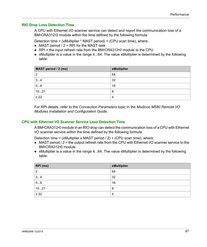
Performance
RIO Drop Loss Detection Time
A CPU with Ethernet I/O scanner service can detect and report the communication loss of a BM•CRA312•0 module within the time defined by the following formula:
Detection time = (xMultiplier * MAST period) + (CPU scan time), where: MAST period / 2 = RPI for the MAST task RPI = the input refresh rate from the BM•CRA312•0 module to the CPU xMultiplier is a value in the range 4...64. The value xMultiplier is determined by the following
table:
For RPI details, refer to the Connection Parameters topic in the Modicon M580 Remote I/O Modules Installation and Configuration Guide.
CPU with Ethernet I/O Scanner Service Loss Detection Time
A BM•CRA312•0 module in an RIO drop can detect the communication loss of a CPU with Ethernet I/O scanner service within the time defined by the following formula:
Detection time = (xMultiplier x MAST period / 2) + (CPU scan time), where: MAST period / 2 = the output refresh rate from the CPU with Ethernet I/O scanner service to the
BM•CRA312•0 module xMultiplier is a value in the range 4...64. The value xMultiplier is determined by the following
table:
MAST period / 2 (ms) xMultiplier
2 64
3...4 32
5...9 16
10...21 8
≥ 22 4
RPI (ms) xMultiplier
2 64
3...4 32
5...9 16
10...21 8
≥ 22 4
HRB62666 12/2015 97

Performance
98 HRB62666 12/2015
Modicon M580 Standalone
System Commissioning and Diagnostics
HRB62666 12/2015
M580 System Commissioning and Diagnostics
Part IIIM580 System Commissioning and Diagnostics
Introduction
This part describes M580 system commissioning and diagnostics.
What Is in This Part?
This part contains the following chapters:
Chapter Chapter Name Page
5 Commissioning 101
6 System Diagnostics 111
HRB62666 12/2015 99

System Commissioning and Diagnostics
100 HRB62666 12/2015
Modicon M580 Standalone
Commissioning
HRB62666 12/2015
Commissioning
Chapter 5Commissioning
Overview
This chapter describes the commissioning process in an M580 system.
What Is in This Chapter?
This chapter contains the following topics:
Topic Page
Setting the Location of the Ethernet RIO Drop 102
Powering Up Modules Without a Downloaded Application 103
Downloading CPU Applications 104
Establishing Transparency between a USB and Device Network 106
Initial Start After Application Download 107
Powering Down/Powering Up Modules 108
Starting and Stopping an Application 109
HRB62666 12/2015 101
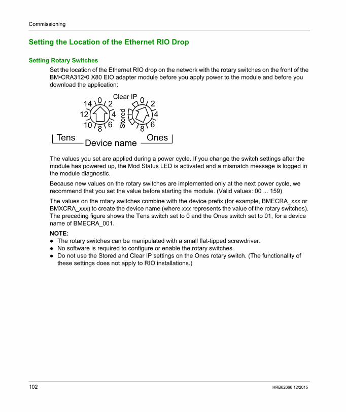
Commissioning
Setting the Location of the Ethernet RIO Drop
Setting Rotary Switches
Set the location of the Ethernet RIO drop on the network with the rotary switches on the front of the BM•CRA312•0 X80 EIO adapter module before you apply power to the module and before you download the application:
The values you set are applied during a power cycle. If you change the switch settings after the module has powered up, the Mod Status LED is activated and a mismatch message is logged in the module diagnostic.
Because new values on the rotary switches are implemented only at the next power cycle, we recommend that you set the value before starting the module. (Valid values: 00 ... 159)
The values on the rotary switches combine with the device prefix (for example, BMECRA_xxx or BMXCRA_xxx) to create the device name (where xxx represents the value of the rotary switches). The preceding figure shows the Tens switch set to 0 and the Ones switch set to 01, for a device name of BMECRA_001.
NOTE: The rotary switches can be manipulated with a small flat-tipped screwdriver. No software is required to configure or enable the rotary switches. Do not use the Stored and Clear IP settings on the Ones rotary switch. (The functionality of
these settings does not apply to RIO installations.)
102 HRB62666 12/2015
Commissioning
Powering Up Modules Without a Downloaded Application
BMEP58•040 IP Address
In the absence of a valid application, a CPU with Ethernet I/O scanner service uses the IP address that is based on the MAC address printed on the front of the module. You can configure the IP address in Unity Pro as detailed in the Modicon M580 Remote I/O Modules Installation and Configuration Guide when you have downloaded an application.
BM•CRA312•0 IP Address
In the absence of an application, the BM•CRA312•0 X80 EIO adapter module unsuccessfully requests an IP address from a CPU with Ethernet I/O scanner service. The adapter module then derives an IP address from the MAC address printed on the front of the module. The module continues in this cycle because it does not have a valid configuration. This Not Configured state is indicated by the LED display on the front of the module. There are no exchanges with the CPU. Physical outputs of I/O modules in the RIO drops are in the fallback state (output forced at 0).
HRB62666 12/2015 103
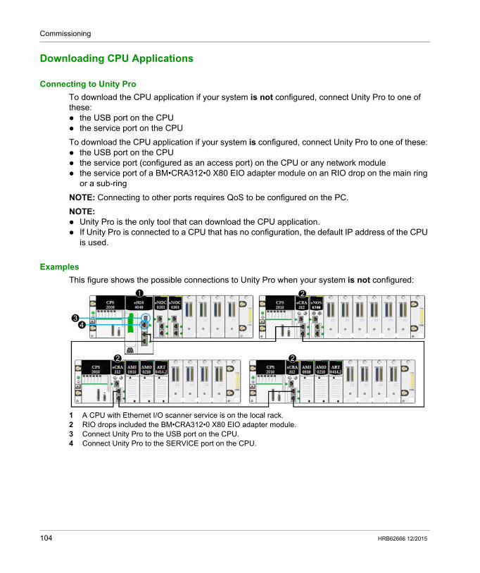
Commissioning
Downloading CPU Applications
Connecting to Unity Pro
To download the CPU application if your system is not configured, connect Unity Pro to one of these: the USB port on the CPU the service port on the CPU
To download the CPU application if your system is configured, connect Unity Pro to one of these: the USB port on the CPU the service port (configured as an access port) on the CPU or any network module the service port of a BM•CRA312•0 X80 EIO adapter module on an RIO drop on the main ring
or a sub-ring
NOTE: Connecting to other ports requires QoS to be configured on the PC.
NOTE: Unity Pro is the only tool that can download the CPU application. If Unity Pro is connected to a CPU that has no configuration, the default IP address of the CPU
is used.
Examples
This figure shows the possible connections to Unity Pro when your system is not configured:
1 A CPU with Ethernet I/O scanner service is on the local rack.2 RIO drops included the BM•CRA312•0 X80 EIO adapter module.3 Connect Unity Pro to the USB port on the CPU.4 Connect Unity Pro to the SERVICE port on the CPU.
104 HRB62666 12/2015
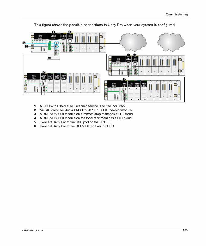
Commissioning
This figure shows the possible connections to Unity Pro when your system is configured:
1 A CPU with Ethernet I/O scanner service is on the local rack.2 An RIO drop includes a BM•CRA31210 X80 EIO adapter module.3 A BMENOS0300 module on a remote drop manages a DIO cloud.4 A BMENOS0300 module on the local rack manages a DIO cloud.5 Connect Unity Pro to the USB port on the CPU.6 Connect Unity Pro to the SERVICE port on the CPU.
HRB62666 12/2015 105
Commissioning
Establishing Transparency between a USB and Device Network
If your M580 system requires transparency between the PC connected to the PAC’s USB port (see Modicon M580, Hardware, Reference Manual) and the device network, add a persistent static route in the PC routing table.
Example of a command to address a device network with the IP address x.x.0.0 (for Windows):
route add x.x.0.0 mask 255.255.0.0 90.0.0.1 -p
106 HRB62666 12/2015
Commissioning
Initial Start After Application Download
Reading the Configuration
At the end of the application download, the CPU configures all modules on the local rack. The CPU’s Ethernet I/O scanner service reads from the CPU memory to get the configuration of the RIO drops declared in the Unity Pro configuration. The configuration of the RIO drops is used to configure the FDR server in the CPU.
At power up, each BM•CRA312•0 X80 EIO adapter module gets an IP address from the CPU’s DHCP server. Then it reads its configuration from the FDR server in the CPU. Finally, the CPU’s Ethernet I/O scanner service initializes the configured I/O modules in the rack.
NOTE: Verify that the IP address on each piece of distributed equipment is correct and unique before initial start.
NOTE: If the BM•CRA312•0 module is powered up first, the IP address is derived from the MAC address printed on the front of the module. The adapter module then performs checks to see if a DHCP server becomes available to distribute an IP address.
The RUN Command
Before receiving a RUN command from the CPU, all RIO drops are configured and connected to the CPU with Ethernet I/O scanner service. The RUN LEDs on the BM•CRA312•0 modules blink to indicate that the CPU is in the STOP state. In the RIO drops, the physical outputs remain in the fallback state (output forced to 0). Input values in the CPU memory image are interpreted as 0.
When the CPU is in RUN state, RIO drops change from the STOP to the RUN state. The LEDs on the BM•CRA312•0 module indicate this change. Output data received from the CPU are applied to physical outputs. Input images in the CPU are updated with physical inputs.
NOTE: For local I/O in the CPU or extended rack and for Premium I/O, there is no change in the comparison with previous versions of CPUs.
HRB62666 12/2015 107
Commissioning
Powering Down/Powering Up Modules
Warm Restart
In a power-up sequence, the BM•CRA312•0 X80 EIO adapter module performs a complete reconfiguration. (There is no backup memory in the BM•CRA312•0 module for saving the configuration.)
A warm start occurs when, after a condition-generated shutdown, the system resumes and the programs running on that system continue at the point they were at when the shutdown occurred. No data is lost in a warm start as long as the CPU contains a valid configuration. When a warm start occurs in RUN mode, there is no requirement to re-execute the application program, even if there are detected errors on the RIO system (the CPU with Ethernet I/O scanner service, the BM•CRA312•0 module, or I/O modules are absent or inoperable).
After the CPU’s Ethernet I/O scanner service restarts, it reads from the CPU memory to get the configuration of RIO drops declared in the Unity Pro configuration. The BM•CRA312•0 modules get the latest configuration.
108 HRB62666 12/2015
Commissioning
Starting and Stopping an Application
CPU Transitions
CPU commands that change states:
NOTE: When the CPU switches from RUN to STOP, the output modules in RIO drops associated with
this task go to the configured fallback state. Input values associated with this task in the CPU memory image are interpreted as 0.
When the CPU switches from STOP to RUN, data received from the CPU are applied to the physical outputs associated with this task. Input images in the CPU are updated with physical inputs associated with this task.
Refer to the Modicon M580 Hardware Reference Manual for CPU configuration options that help prevent remote commands from accessing the Run/Stop modes (see Modicon M580, Hardware, Reference Manual).
Refer to the Modicon M580 Hot Standby System Planning Guide for Frequently Used Architectures.
Command Description
STOP CPU CPU tasks go to the STOP state.
RUN CPU CPU tasks go to the RUN state.
RUN Task The relevant tasks and the CPU go to the RUN state.
STOP Task The relevant task goes to the STOP state. The CPU goes to the STOP state if this task was the last task in the RUN state.
HRB62666 12/2015 109

Commissioning
110 HRB62666 12/2015
Modicon M580 Standalone
System Diagnostics
HRB62666 12/2015
System Diagnostics
Chapter 6System Diagnostics
Overview
This chapter describes system diagnostics in an M580 system.
NOTE: For diagnostics at the module level, refer to the respective module user guide. For the CPU with Ethernet I/O scanner service, refer to the Modicon M580 CPU documentation
(see Modicon M580, Hardware, Reference Manual). For the BM•CRA312•0 X80 EIO adapter module, refer to the BM•CRA312•0 user guide
(see Modicon M580, RIO Modules, Installation and Configuration Guide). For the BMENOC03•1 Ethernet communication module, refer to the BMENOC03•1 user guide
(see Modicon M580, BMENOC03•1 Ethernet Communications Module, Installation and Configuration Guide).
What Is in This Chapter?
This chapter contains the following topics:
Topic Page
System Diagnostics 112
Main Ring Diagnostics 116
HRB62666 12/2015 111
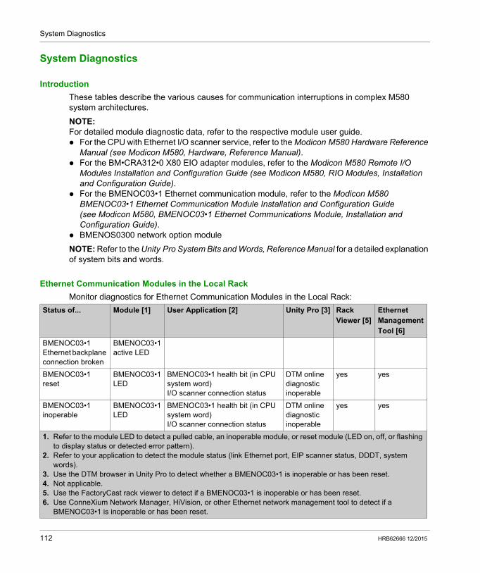
System Diagnostics
System Diagnostics
Introduction
These tables describe the various causes for communication interruptions in complex M580 system architectures.
NOTE: For detailed module diagnostic data, refer to the respective module user guide. For the CPU with Ethernet I/O scanner service, refer to the Modicon M580 Hardware Reference
Manual (see Modicon M580, Hardware, Reference Manual). For the BM•CRA312•0 X80 EIO adapter modules, refer to the Modicon M580 Remote I/O
Modules Installation and Configuration Guide (see Modicon M580, RIO Modules, Installation and Configuration Guide).
For the BMENOC03•1 Ethernet communication module, refer to the Modicon M580 BMENOC03•1 Ethernet Communication Module Installation and Configuration Guide (see Modicon M580, BMENOC03•1 Ethernet Communications Module, Installation and Configuration Guide).
BMENOS0300 network option module
NOTE: Refer to the Unity Pro System Bits and Words, Reference Manual for a detailed explanation of system bits and words.
Ethernet Communication Modules in the Local Rack
Monitor diagnostics for Ethernet Communication Modules in the Local Rack:
Status of... Module [1] User Application [2] Unity Pro [3] Rack Viewer [5]
Ethernet Management Tool [6]
BMENOC03•1 Ethernet backplane connection broken
BMENOC03•1 active LED
BMENOC03•1 reset
BMENOC03•1 LED
BMENOC03•1 health bit (in CPU system word)I/O scanner connection status
DTM online diagnostic inoperable
yes yes
BMENOC03•1 inoperable
BMENOC03•1 LED
BMENOC03•1 health bit (in CPU system word)I/O scanner connection status
DTM online diagnostic inoperable
yes yes
1. Refer to the module LED to detect a pulled cable, an inoperable module, or reset module (LED on, off, or flashing to display status or detected error pattern).
2. Refer to your application to detect the module status (link Ethernet port, EIP scanner status, DDDT, system words).
3. Use the DTM browser in Unity Pro to detect whether a BMENOC03•1 is inoperable or has been reset.4. Not applicable.5. Use the FactoryCast rack viewer to detect if a BMENOC03•1 is inoperable or has been reset.6. Use ConneXium Network Manager, HiVision, or other Ethernet network management tool to detect if a
BMENOC03•1 is inoperable or has been reset.
112 HRB62666 12/2015
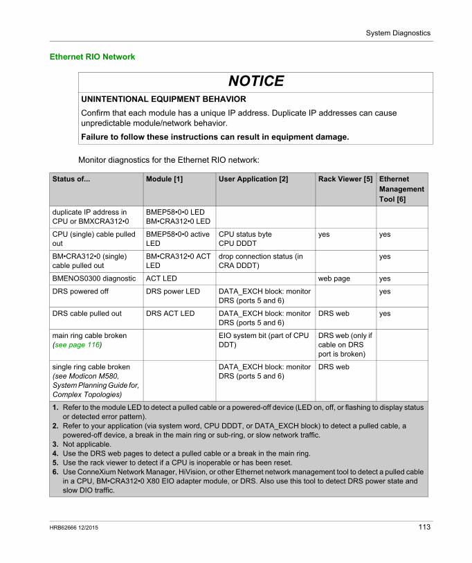
System Diagnostics
Ethernet RIO Network
Monitor diagnostics for the Ethernet RIO network:
NOTICEUNINTENTIONAL EQUIPMENT BEHAVIOR
Confirm that each module has a unique IP address. Duplicate IP addresses can cause unpredictable module/network behavior.
Failure to follow these instructions can result in equipment damage.
Status of... Module [1] User Application [2] Rack Viewer [5] Ethernet Management Tool [6]
duplicate IP address in CPU or BMXCRA312•0
BMEP58•0•0 LEDBM•CRA312•0 LED
CPU (single) cable pulled out
BMEP58•0•0 active LED
CPU status byteCPU DDDT
yes yes
BM•CRA312•0 (single) cable pulled out
BM•CRA312•0 ACT LED
drop connection status (in CRA DDDT)
yes
BMENOS0300 diagnostic ACT LED web page yes
DRS powered off DRS power LED DATA_EXCH block: monitor DRS (ports 5 and 6)
yes
DRS cable pulled out DRS ACT LED DATA_EXCH block: monitor DRS (ports 5 and 6)
DRS web yes
main ring cable broken (see page 116)
EIO system bit (part of CPU DDT)
DRS web (only if cable on DRS port is broken)
single ring cable broken (see Modicon M580, System Planning Guide for, Complex Topologies)
DATA_EXCH block: monitor DRS (ports 5 and 6)
DRS web
1. Refer to the module LED to detect a pulled cable or a powered-off device (LED on, off, or flashing to display status or detected error pattern).
2. Refer to your application (via system word, CPU DDDT, or DATA_EXCH block) to detect a pulled cable, a powered-off device, a break in the main ring or sub-ring, or slow network traffic.
3. Not applicable.4. Use the DRS web pages to detect a pulled cable or a break in the main ring.5. Use the rack viewer to detect if a CPU is inoperable or has been reset.6. Use ConneXium Network Manager, HiVision, or other Ethernet network management tool to detect a pulled cable
in a CPU, BM•CRA312•0 X80 EIO adapter module, or DRS. Also use this tool to detect DRS power state and slow DIO traffic.
HRB62666 12/2015 113
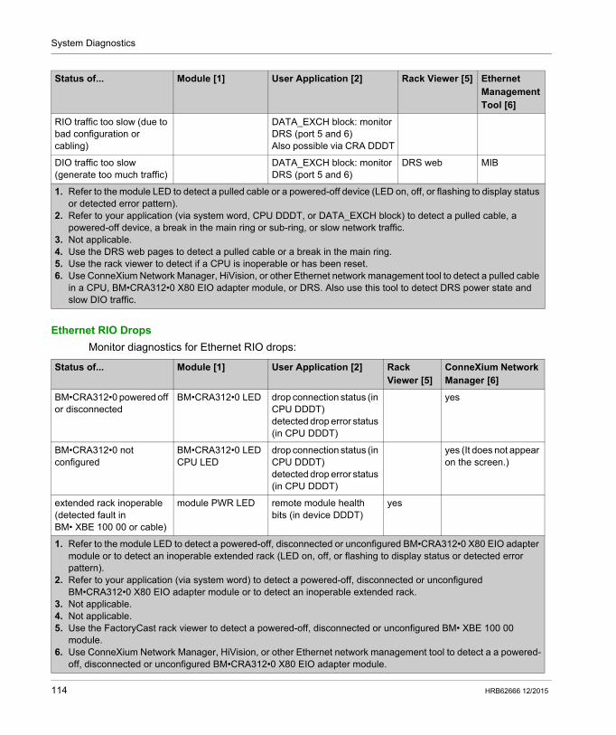
System Diagnostics
Ethernet RIO Drops
Monitor diagnostics for Ethernet RIO drops:
RIO traffic too slow (due to bad configuration or cabling)
DATA_EXCH block: monitor DRS (port 5 and 6)Also possible via CRA DDDT
DIO traffic too slow (generate too much traffic)
DATA_EXCH block: monitor DRS (port 5 and 6)
DRS web MIB
Status of... Module [1] User Application [2] Rack Viewer [5] Ethernet Management Tool [6]
1. Refer to the module LED to detect a pulled cable or a powered-off device (LED on, off, or flashing to display status or detected error pattern).
2. Refer to your application (via system word, CPU DDDT, or DATA_EXCH block) to detect a pulled cable, a powered-off device, a break in the main ring or sub-ring, or slow network traffic.
3. Not applicable.4. Use the DRS web pages to detect a pulled cable or a break in the main ring.5. Use the rack viewer to detect if a CPU is inoperable or has been reset.6. Use ConneXium Network Manager, HiVision, or other Ethernet network management tool to detect a pulled cable
in a CPU, BM•CRA312•0 X80 EIO adapter module, or DRS. Also use this tool to detect DRS power state and slow DIO traffic.
Status of... Module [1] User Application [2] Rack Viewer [5]
ConneXium Network Manager [6]
BM•CRA312•0 powered off or disconnected
BM•CRA312•0 LED drop connection status (in CPU DDDT)detected drop error status (in CPU DDDT)
yes
BM•CRA312•0 not configured
BM•CRA312•0 LEDCPU LED
drop connection status (in CPU DDDT)detected drop error status (in CPU DDDT)
yes (It does not appear on the screen.)
extended rack inoperable (detected fault in BM• XBE 100 00 or cable)
module PWR LED remote module health bits (in device DDDT)
yes
1. Refer to the module LED to detect a powered-off, disconnected or unconfigured BM•CRA312•0 X80 EIO adapter module or to detect an inoperable extended rack (LED on, off, or flashing to display status or detected error pattern).
2. Refer to your application (via system word) to detect a powered-off, disconnected or unconfigured BM•CRA312•0 X80 EIO adapter module or to detect an inoperable extended rack.
3. Not applicable.4. Not applicable.5. Use the FactoryCast rack viewer to detect a powered-off, disconnected or unconfigured BM• XBE 100 00
module.6. Use ConneXium Network Manager, HiVision, or other Ethernet network management tool to detect a a powered-
off, disconnected or unconfigured BM•CRA312•0 X80 EIO adapter module.
114 HRB62666 12/2015
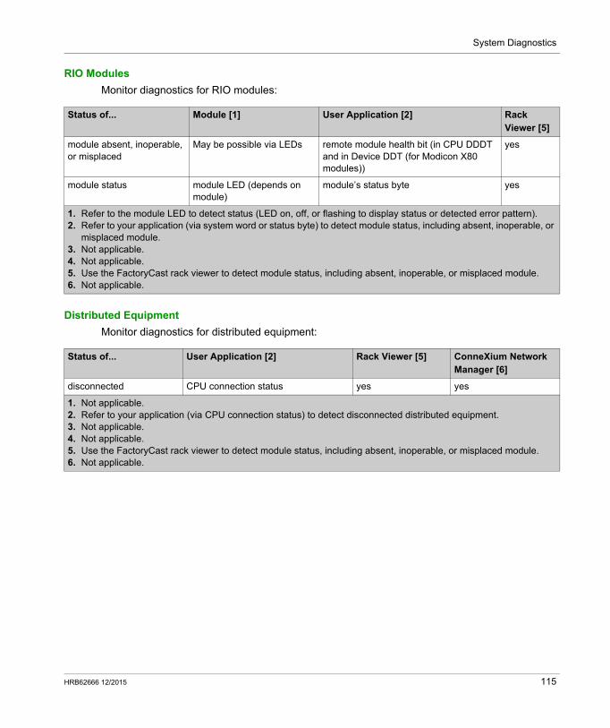
System Diagnostics
RIO Modules
Monitor diagnostics for RIO modules:
Distributed Equipment
Monitor diagnostics for distributed equipment:
Status of... Module [1] User Application [2] Rack Viewer [5]
module absent, inoperable, or misplaced
May be possible via LEDs remote module health bit (in CPU DDDT and in Device DDT (for Modicon X80 modules))
yes
module status module LED (depends on module)
module’s status byte yes
1. Refer to the module LED to detect status (LED on, off, or flashing to display status or detected error pattern).2. Refer to your application (via system word or status byte) to detect module status, including absent, inoperable, or
misplaced module.3. Not applicable.4. Not applicable.5. Use the FactoryCast rack viewer to detect module status, including absent, inoperable, or misplaced module.6. Not applicable.
Status of... User Application [2] Rack Viewer [5] ConneXium Network Manager [6]
disconnected CPU connection status yes yes
1. Not applicable.2. Refer to your application (via CPU connection status) to detect disconnected distributed equipment.3. Not applicable.4. Not applicable.5. Use the FactoryCast rack viewer to detect module status, including absent, inoperable, or misplaced module.6. Not applicable.
HRB62666 12/2015 115
System Diagnostics
Main Ring Diagnostics
Diagnosing the RIO Main Ring
You can monitor breaks in the main ring by diagnosing the REDUNDANCY_STATUS bits in the CPU with Ethernet I/O scanner service on the local rack DDT. The system detects and reports in this bit a main ring cable break that persists for at least 5 seconds.
Within the REDUNDANCY_STATUS bit: 0 = A cable is broken or a device has stopped. 1 = loop is present and healthy.
NOTE: Refer to the M580 RIO guide (see Modicon M580, RIO Modules, Installation and Configuration Guide) for a list of diagnostic status bits.
116 HRB62666 12/2015

Modicon M580 Standalone
HRB62666 12/2015
Appendices
What Is in This Appendix?
The appendix contains the following chapters:
Chapter Chapter Name Page
A Frequently Asked Questions (FAQ) 119
B Detected Error Codes 127
C Design Principles of M580 Networks 135
HRB62666 12/2015 117

118 HRB62666 12/2015
Modicon M580 Standalone
Frequently Asked Questions (FAQ)
HRB62666 12/2015
Frequently Asked Questions (FAQ)
Appendix AFrequently Asked Questions (FAQ)
Frequently Asked Questions (FAQ)
Connection
Why can’t I connect the CPU in Unity Pro?
Possible cause:
A BME XBE 1000 rack extender module may be installed on the main local rack without the presence of an extended local rack.
Possible solution:
Remove the BME XBE 1000 module from the main local rack, or add an extended local rack.
Why can’t I connect to the CPU with Unity Loader?
Possible cause:
By default, the FTP service in the CPU is disabled (cyber security (see Modicon Controllers Platform, Cyber Security, Reference Manual) default setting). Unity Loader does not connect to the CPU if this service is disabled.
Possible solution:
Enable the FTP service in the CPU by downloading an application, in which the FTP service is enabled, to the CPU.
How can I upgrade a BM• CRA 312 •0 (e)X80 EIO adapter module that is not yet configured?
The BM• CRA 312 •0 module receives its IP address from the CPU at startup. If the CPU is not configured or the firmware version of the BM• CRA 312 •0 module is not compatible, the BM• CRA 312 •0 module does not receive an IP address.
Set the rotary switches on the BM• CRA 312 •0 module to stored. Power cycle the BM• CRA 312 •0 module. Connect the BM• CRA 312 •0 module via its service port to Unity Loader using the IP address: 10.10.mac5.mac6.
HRB62666 12/2015 119
Frequently Asked Questions (FAQ)
ConneXium Network Manager
Why can’t I discover IMPRs? I installed the ConneXium Network Manager tool, but the IMPRs are shown as Modbus devices.
Possible cause: You may not have the latest version of ConneXium Network Manager. You may not have specified the GET community name while discovering the network.
Possible solution: Install the latest version of ConneXium Network Manager or contact Schneider Electric support
to get the Ethernet IMPR device types. Add the GET community name of the IMPR before discovering the network. You can retrieve the
GET community name by reading the configuration using PowerSuite. By default, the IMPR GET community name is public_1.
Why is ConneXium Network Manager taking such a long time to discover the network?
Possible cause: The parameters you selected before discovering the network may be slowing down the process.
Possible solution: You can speed up the network discovery by adjusting the tool discovery parameters. Please
read the ConneXium Network Manager Ethernet Diagnostic Tool Reference Guide.NOTE: If you increase the network discovery speed, you will also increase network traffic.
Why does ConneXium Network Manager display the IMPRs in a star topology when I have the IMPRs connected in a daisy chain or daisy chain loop topology?
Possible cause: ConneXium Network Manager does not currently support daisy chain and daisy chain loop
topologies. Please contact ConneXium Network Manager support to find out when these topologies will be supported.
Possible solution: Manually edit the network topology that ConneXium Network Manager displays to create your
own topology.
Why does ConneXium Network Manager say that my IP address has an invalid gateway?
Possible cause:
When you enter a gateway address, ConneXium Network Manager does 2 things: validates that the gateway address is in the same subnet as the IP address contacts the gateway address If a response is received from the gateway address, ConneXium Network Manager discovers
if the address is actually a gateway/router address. If the address is not an actual gateway/router address, ConneXium Network Manager displays a detected error message.
If no response is received from the gateway address, ConneXium Network Manager takes no action.
120 HRB62666 12/2015
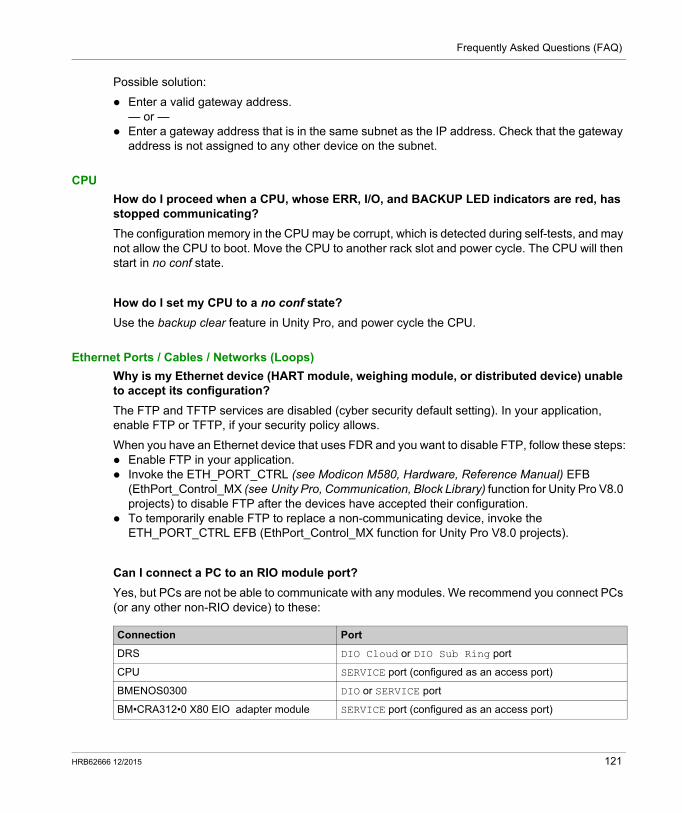
Frequently Asked Questions (FAQ)
Possible solution:
Enter a valid gateway address.— or —
Enter a gateway address that is in the same subnet as the IP address. Check that the gateway address is not assigned to any other device on the subnet.
CPU
How do I proceed when a CPU, whose ERR, I/O, and BACKUP LED indicators are red, has stopped communicating?
The configuration memory in the CPU may be corrupt, which is detected during self-tests, and may not allow the CPU to boot. Move the CPU to another rack slot and power cycle. The CPU will then start in no conf state.
How do I set my CPU to a no conf state?
Use the backup clear feature in Unity Pro, and power cycle the CPU.
Ethernet Ports / Cables / Networks (Loops)
Why is my Ethernet device (HART module, weighing module, or distributed device) unable to accept its configuration?
The FTP and TFTP services are disabled (cyber security default setting). In your application, enable FTP or TFTP, if your security policy allows.
When you have an Ethernet device that uses FDR and you want to disable FTP, follow these steps: Enable FTP in your application. Invoke the ETH_PORT_CTRL (see Modicon M580, Hardware, Reference Manual) EFB
(EthPort_Control_MX (see Unity Pro, Communication, Block Library) function for Unity Pro V8.0 projects) to disable FTP after the devices have accepted their configuration.
To temporarily enable FTP to replace a non-communicating device, invoke the ETH_PORT_CTRL EFB (EthPort_Control_MX function for Unity Pro V8.0 projects).
Can I connect a PC to an RIO module port?
Yes, but PCs are not be able to communicate with any modules. We recommend you connect PCs (or any other non-RIO device) to these:
Connection Port
DRS DIO Cloud or DIO Sub Ring port
CPU SERVICE port (configured as an access port)
BMENOS0300 DIO or SERVICE port
BM•CRA312•0 X80 EIO adapter module SERVICE port (configured as an access port)
HRB62666 12/2015 121
Frequently Asked Questions (FAQ)
Function Blocks
Why aren’t the PRINT_CHAR_QX and INPUT_CHAR_QX function blocks working with my Unity Pro 7.0 application, after I upgraded (or replaced) the BMX CRA 312 •0 X80 EIO adapter module?
The firmware in the BMX CRA 312 •0 module has evolved to increase its robustness. This evolution is not compatible with the PRINT_CHAR_QX and INPUT_CHAR_QX function blocks in Unity Pro 7.0.
Perform one of the following to make these function blocks operate: Migrate the application to Unity Pro 8.x.
– or – Downgrade the BMX CRA 312 •0 module to version 1.30.
IP Addressing / FDR
Can I use the stored and clear IP rotary switch positions on the BM• CRA 312 •0 X80 EIO adapter modules?
We recommend that you do not use these switch positions (see page 102) on the rotary switches because they do not support I/O module management. The only way to manage I/O modules is to use the ones and tens positions.
IPsec
For questions regarding IP secure communications (IPsec), refer to BMENOC03•1 guide (see Modicon M580, BMENOC03•1 Ethernet Communications Module, Installation and Configuration Guide).
Remote I/O
What happens if I measure an application response time (ART) that is higher than I expected?
If the MAST task is cyclic, the default RPI is set to 60 ms. If the actual execution time of the MAST task is lower than 120 ms, the ART is affected by the RPI.
Adjust the RPI value to your needs, or set your MAST task in periodic mode.
Time
How can I display the local time when %MW49...53 seem to be in UTC?
The words %MW49...53 are in universal coordinated time (UTC), not in local time. If you require local time, use the RRTC_DT function block. (NOTE: RRTC_DT_MS is also in UTC time.)
122 HRB62666 12/2015
Frequently Asked Questions (FAQ)
Topologies
Do we have to follow the topology rules given in the user guide?
Yes, the system has been tested with the topology rules provided (see page 51). The level of determinism and the operating characteristics of the network described in this document are based on a system designed according to these rules.
Can I connect DIO scanner devices (M340, Premium) to DIO ports or clouds or in a DIO network?
We recommend that you do not add these devices to DIO ports. Each DIO port on DRSs / BM•CRA312•0 X80 EIO adapter modules has a bandwidth that determines how much traffic is allowed on the M580 main ring. This bandwidth limitation can cause DIO scanner performance to decrease, which may be unacceptable in your network.
What type of distributed equipment can I connect to DIO ports or clouds?
You can connect devices that do not support 802.1D/Q tagging.
Example: Advantys, TeSyS-T, Momentum, and non-Schneider devices
Can I access devices (via ping, PC tools) in an M580 network via the SERVICE port (ETH1) when it is configured in port mirror mode?
No. When the SERVICE port is configured in port mirror mode, you cannot access devices, that is, you cannot ping other devices by connecting a PC to ETH1 in port mirror mode. When the SERVICE port is configured in access mode, then you can access devices in an M580 network via any tool.
Unity Loader
What is the correct procedure to upgrade the BME NOC 03•0 Ethernet communication module?
Upgrade the BME NOC 03•0 module by connecting Unity Loader to the Ethernet port of the BME NOC 03•0 module. The connection can be direct or via a dual-ring switch (DRS).
You cannot use the USB port of the CPU to access the BME NOC 03•0 module. The following message appears: “Upgrade error: Com = CallBack (on channel 10 index 0 and channel 10 index 5).”
Can I upgrade the CPU’s firmware via the BME NOC 03•0 module?
Yes, you can connect the BME NOC 03•0 module’s embedded Ethernet switch to the CPU. Check that the BME NOC 03•0 module is running properly before starting the upgrade procedure.
You cannot, however, upgrade the CPU if Unity Loader is connected on the BME NOC 03•0 module’s IP address.
HRB62666 12/2015 123
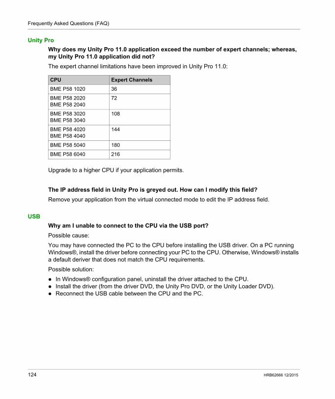
Frequently Asked Questions (FAQ)
Unity Pro
Why does my Unity Pro 11.0 application exceed the number of expert channels; whereas, my Unity Pro 11.0 application did not?
The expert channel limitations have been improved in Unity Pro 11.0:
Upgrade to a higher CPU if your application permits.
The IP address field in Unity Pro is greyed out. How can I modify this field?
Remove your application from the virtual connected mode to edit the IP address field.
USB
Why am I unable to connect to the CPU via the USB port?
Possible cause:
You may have connected the PC to the CPU before installing the USB driver. On a PC running Windows®, install the driver before connecting your PC to the CPU. Otherwise, Windows® installs a default deriver that does not match the CPU requirements.
Possible solution:
In Windows® configuration panel, uninstall the driver attached to the CPU. Install the driver (from the driver DVD, the Unity Pro DVD, or the Unity Loader DVD). Reconnect the USB cable between the CPU and the PC.
CPU Expert Channels
BME P58 1020 36
BME P58 2020BME P58 2040
72
BME P58 3020BME P58 3040
108
BME P58 4020BME P58 4040
144
BME P58 5040 180
BME P58 6040 216
124 HRB62666 12/2015
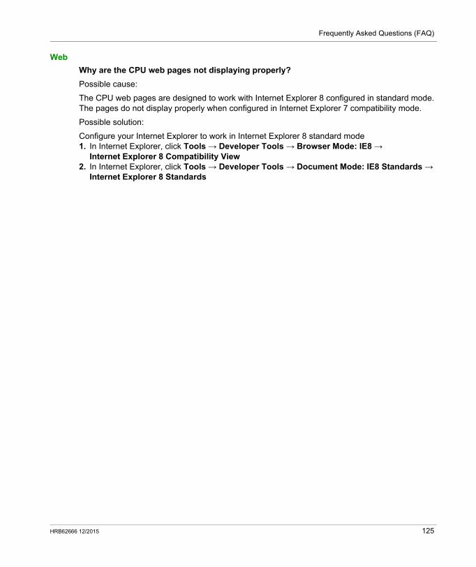
Frequently Asked Questions (FAQ)
Web
Why are the CPU web pages not displaying properly?
Possible cause:
The CPU web pages are designed to work with Internet Explorer 8 configured in standard mode. The pages do not display properly when configured in Internet Explorer 7 compatibility mode.
Possible solution:
Configure your Internet Explorer to work in Internet Explorer 8 standard mode1. In Internet Explorer, click Tools → Developer Tools → Browser Mode: IE8 →
Internet Explorer 8 Compatibility View2. In Internet Explorer, click Tools → Developer Tools → Document Mode: IE8 Standards →
Internet Explorer 8 Standards
HRB62666 12/2015 125

Frequently Asked Questions (FAQ)
126 HRB62666 12/2015
Modicon M580 Standalone
Detected Error Codes
HRB62666 12/2015
Detected Error Codes
Appendix BDetected Error Codes
Overview
This chapter contains a list of codes that describe the status of Ethernet communication module messages.
What Is in This Chapter?
This chapter contains the following topics:
Topic Page
EtherNet/IP Implicit or Explicit Messaging Detected Error Codes 128
Explicit Messaging: Communication and Operation Reports 131
HRB62666 12/2015 127
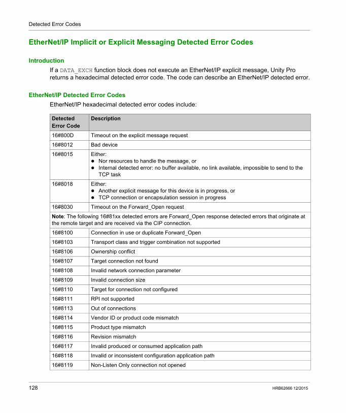
Detected Error Codes
EtherNet/IP Implicit or Explicit Messaging Detected Error Codes
Introduction
If a DATA_EXCH function block does not execute an EtherNet/IP explicit message, Unity Pro returns a hexadecimal detected error code. The code can describe an EtherNet/IP detected error.
EtherNet/IP Detected Error Codes
EtherNet/IP hexadecimal detected error codes include:
Detected Error Code
Description
16#800D Timeout on the explicit message request
16#8012 Bad device
16#8015 Either: Nor resources to handle the message, or Internal detected error: no buffer available, no link available, impossible to send to the
TCP task
16#8018 Either: Another explicit message for this device is in progress, or TCP connection or encapsulation session in progress
16#8030 Timeout on the Forward_Open request
Note: The following 16#81xx detected errors are Forward_Open response detected errors that originate at the remote target and are received via the CIP connection.
16#8100 Connection in use or duplicate Forward_Open
16#8103 Transport class and trigger combination not supported
16#8106 Ownership conflict
16#8107 Target connection not found
16#8108 Invalid network connection parameter
16#8109 Invalid connection size
16#8110 Target for connection not configured
16#8111 RPI not supported
16#8113 Out of connections
16#8114 Vendor ID or product code mismatch
16#8115 Product type mismatch
16#8116 Revision mismatch
16#8117 Invalid produced or consumed application path
16#8118 Invalid or inconsistent configuration application path
16#8119 Non-Listen Only connection not opened
128 HRB62666 12/2015
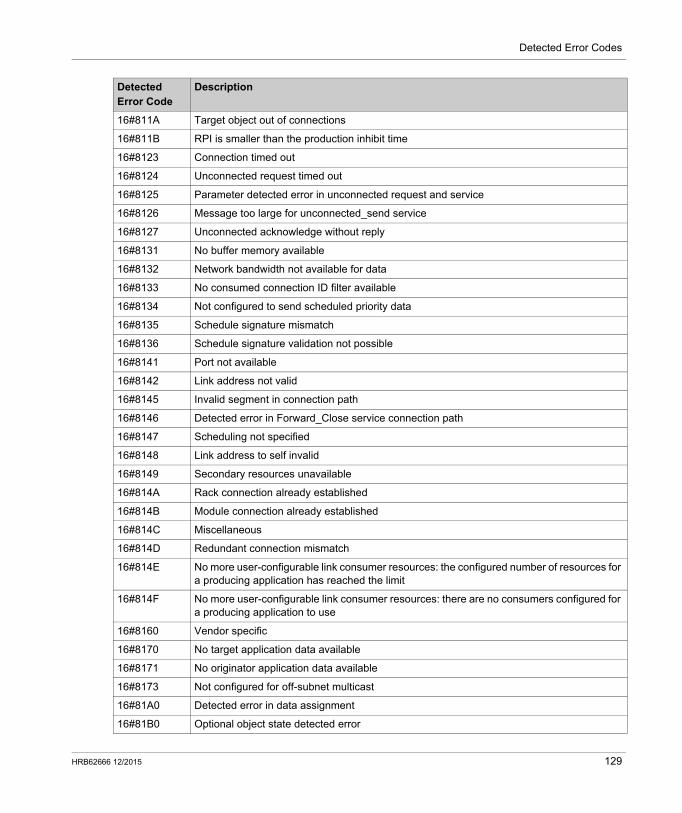
Detected Error Codes
16#811A Target object out of connections
16#811B RPI is smaller than the production inhibit time
16#8123 Connection timed out
16#8124 Unconnected request timed out
16#8125 Parameter detected error in unconnected request and service
16#8126 Message too large for unconnected_send service
16#8127 Unconnected acknowledge without reply
16#8131 No buffer memory available
16#8132 Network bandwidth not available for data
16#8133 No consumed connection ID filter available
16#8134 Not configured to send scheduled priority data
16#8135 Schedule signature mismatch
16#8136 Schedule signature validation not possible
16#8141 Port not available
16#8142 Link address not valid
16#8145 Invalid segment in connection path
16#8146 Detected error in Forward_Close service connection path
16#8147 Scheduling not specified
16#8148 Link address to self invalid
16#8149 Secondary resources unavailable
16#814A Rack connection already established
16#814B Module connection already established
16#814C Miscellaneous
16#814D Redundant connection mismatch
16#814E No more user-configurable link consumer resources: the configured number of resources for a producing application has reached the limit
16#814F No more user-configurable link consumer resources: there are no consumers configured for a producing application to use
16#8160 Vendor specific
16#8170 No target application data available
16#8171 No originator application data available
16#8173 Not configured for off-subnet multicast
16#81A0 Detected error in data assignment
16#81B0 Optional object state detected error
Detected Error Code
Description
HRB62666 12/2015 129
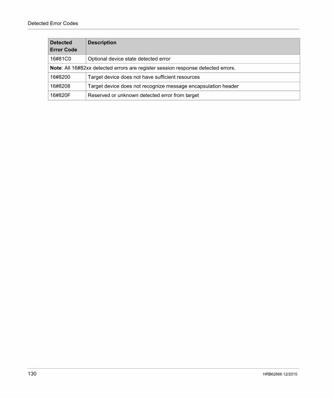
Detected Error Codes
16#81C0 Optional device state detected error
Note: All 16#82xx detected errors are register session response detected errors.
16#8200 Target device does not have sufficient resources
16#8208 Target device does not recognize message encapsulation header
16#820F Reserved or unknown detected error from target
Detected Error Code
Description
130 HRB62666 12/2015
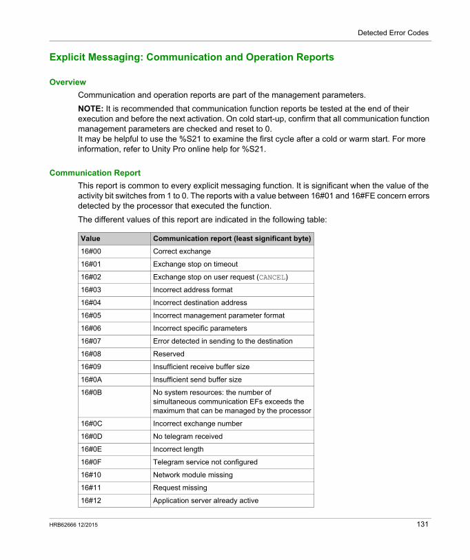
Detected Error Codes
Explicit Messaging: Communication and Operation Reports
Overview
Communication and operation reports are part of the management parameters.
NOTE: It is recommended that communication function reports be tested at the end of their execution and before the next activation. On cold start-up, confirm that all communication function management parameters are checked and reset to 0.It may be helpful to use the %S21 to examine the first cycle after a cold or warm start. For more information, refer to Unity Pro online help for %S21.
Communication Report
This report is common to every explicit messaging function. It is significant when the value of the activity bit switches from 1 to 0. The reports with a value between 16#01 and 16#FE concern errors detected by the processor that executed the function.
The different values of this report are indicated in the following table:
Value Communication report (least significant byte)
16#00 Correct exchange
16#01 Exchange stop on timeout
16#02 Exchange stop on user request (CANCEL)
16#03 Incorrect address format
16#04 Incorrect destination address
16#05 Incorrect management parameter format
16#06 Incorrect specific parameters
16#07 Error detected in sending to the destination
16#08 Reserved
16#09 Insufficient receive buffer size
16#0A Insufficient send buffer size
16#0B No system resources: the number of simultaneous communication EFs exceeds the maximum that can be managed by the processor
16#0C Incorrect exchange number
16#0D No telegram received
16#0E Incorrect length
16#0F Telegram service not configured
16#10 Network module missing
16#11 Request missing
16#12 Application server already active
HRB62666 12/2015 131
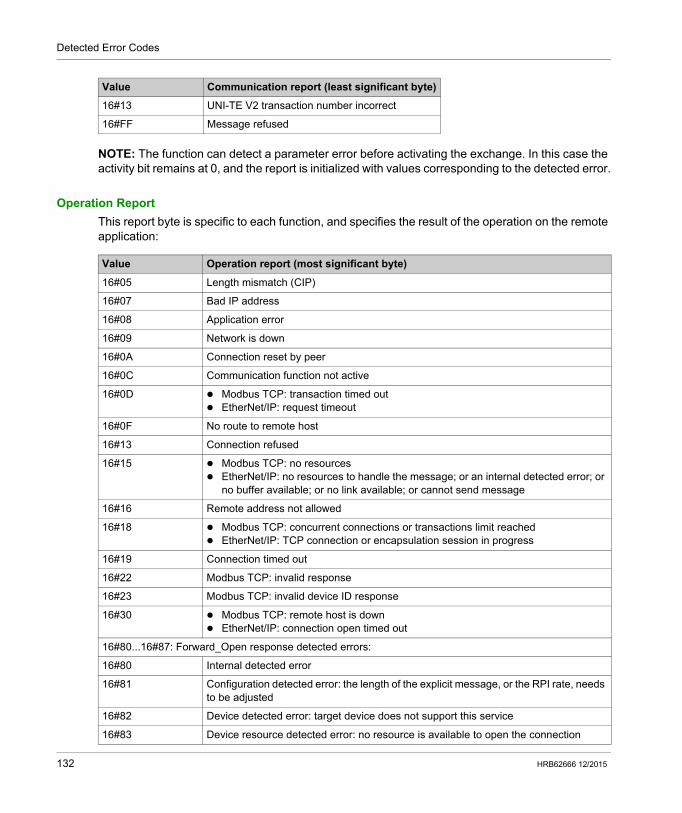
Detected Error Codes
NOTE: The function can detect a parameter error before activating the exchange. In this case the activity bit remains at 0, and the report is initialized with values corresponding to the detected error.
Operation Report
This report byte is specific to each function, and specifies the result of the operation on the remote application:
16#13 UNI-TE V2 transaction number incorrect
16#FF Message refused
Value Communication report (least significant byte)
Value Operation report (most significant byte)
16#05 Length mismatch (CIP)
16#07 Bad IP address
16#08 Application error
16#09 Network is down
16#0A Connection reset by peer
16#0C Communication function not active
16#0D Modbus TCP: transaction timed out EtherNet/IP: request timeout
16#0F No route to remote host
16#13 Connection refused
16#15 Modbus TCP: no resources EtherNet/IP: no resources to handle the message; or an internal detected error; or
no buffer available; or no link available; or cannot send message
16#16 Remote address not allowed
16#18 Modbus TCP: concurrent connections or transactions limit reached EtherNet/IP: TCP connection or encapsulation session in progress
16#19 Connection timed out
16#22 Modbus TCP: invalid response
16#23 Modbus TCP: invalid device ID response
16#30 Modbus TCP: remote host is down EtherNet/IP: connection open timed out
16#80...16#87: Forward_Open response detected errors:
16#80 Internal detected error
16#81 Configuration detected error: the length of the explicit message, or the RPI rate, needs to be adjusted
16#82 Device detected error: target device does not support this service
16#83 Device resource detected error: no resource is available to open the connection
132 HRB62666 12/2015
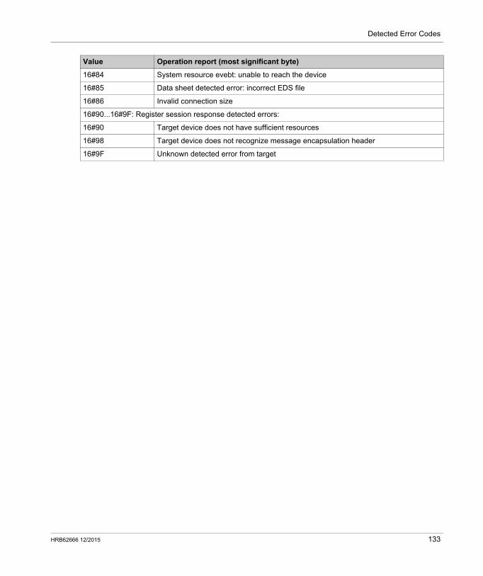
Detected Error Codes
16#84 System resource evebt: unable to reach the device
16#85 Data sheet detected error: incorrect EDS file
16#86 Invalid connection size
16#90...16#9F: Register session response detected errors:
16#90 Target device does not have sufficient resources
16#98 Target device does not recognize message encapsulation header
16#9F Unknown detected error from target
Value Operation report (most significant byte)
HRB62666 12/2015 133

Detected Error Codes
134 HRB62666 12/2015
Modicon M580 Standalone
Design Principles of M580 Networks
HRB62666 12/2015
Design Principles of M580 Networks
Appendix CDesign Principles of M580 Networks
Overview
This chapter describes the design principles for the following types of M580 network topologies: a main ring, with RIO sub-rings a main ring, with both RIO and DIO sub-rings
What Is in This Chapter?
This chapter contains the following sections:
Section Topic Page
C.1 Network Determinism Parameters 136
C.2 RIO Network Design Principles 137
C.3 RIO with DIO Network Design Principles 141
HRB62666 12/2015 135
Design Principles of M580 Networks
Network Determinism Parameters
Section C.1Network Determinism Parameters
Network Determinism Parameters
Introduction
Determinism refers to the ability to calculate and predict application response time (ART), which is the time required for an M580 network system to detect and respond to a single input. When you calculate ART for your application, consider the following: An M580 architecture features a dedicated module for RIO communications. Each remote packet travels from an input module in the remote drop to the controller, then back
to an output module in the remote drop. Hop count is defined as the number of switches (including switches embedded in RIO devices)
that a packet passes through to reach its destination. Packet path impacts jitter calculations, because of potential queue delays along its path. For RIO ART calculations: Consider the worst case, i.e., the longest path a packet may need to travel in case of a broken
network cable. RIO only provides recovery from a single break in the system. This remains true even if a
packet is able to arrive at its destination when multiple breaks exist in the system. Only count hops and jitter delays along the network path, i.e., from the perspective of the
specific RIO adapter module transmitting the packet. Do not include hops and jitter for other devices in the system that are not on the network path.
136 HRB62666 12/2015
Design Principles of M580 Networks
RIO Network Design Principles
Section C.2RIO Network Design Principles
Overview
This section describes the design principles for M580 network topologies that consist exclusively of main rings and optional RIO sub-rings.
What Is in This Section?
This section contains the following topics:
Topic Page
RIO Network Design Principles 138
Defined Architecture: Topologies 139
Defined Architecture: Junctions 140
HRB62666 12/2015 137
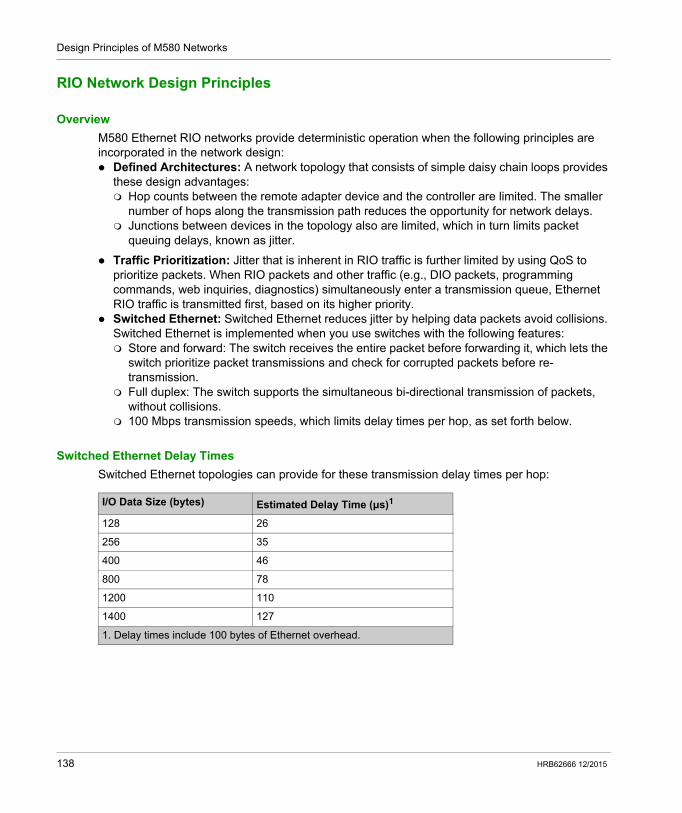
Design Principles of M580 Networks
RIO Network Design Principles
Overview
M580 Ethernet RIO networks provide deterministic operation when the following principles are incorporated in the network design: Defined Architectures: A network topology that consists of simple daisy chain loops provides
these design advantages: Hop counts between the remote adapter device and the controller are limited. The smaller
number of hops along the transmission path reduces the opportunity for network delays. Junctions between devices in the topology also are limited, which in turn limits packet
queuing delays, known as jitter.
Traffic Prioritization: Jitter that is inherent in RIO traffic is further limited by using QoS to prioritize packets. When RIO packets and other traffic (e.g., DIO packets, programming commands, web inquiries, diagnostics) simultaneously enter a transmission queue, Ethernet RIO traffic is transmitted first, based on its higher priority.
Switched Ethernet: Switched Ethernet reduces jitter by helping data packets avoid collisions. Switched Ethernet is implemented when you use switches with the following features: Store and forward: The switch receives the entire packet before forwarding it, which lets the
switch prioritize packet transmissions and check for corrupted packets before re-transmission.
Full duplex: The switch supports the simultaneous bi-directional transmission of packets, without collisions.
100 Mbps transmission speeds, which limits delay times per hop, as set forth below.
Switched Ethernet Delay Times
Switched Ethernet topologies can provide for these transmission delay times per hop:
I/O Data Size (bytes) Estimated Delay Time (μs)1
128 26
256 35
400 46
800 78
1200 110
1400 127
1. Delay times include 100 bytes of Ethernet overhead.
138 HRB62666 12/2015
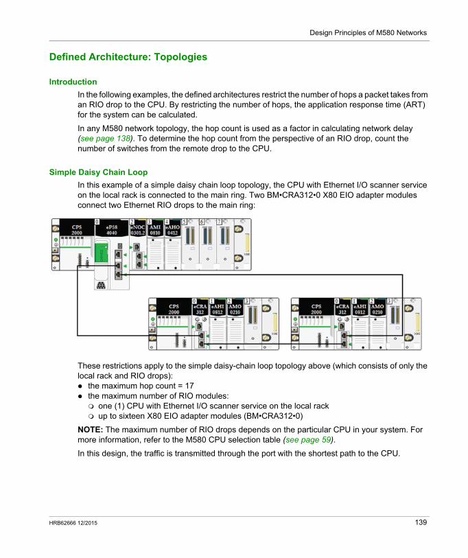
Design Principles of M580 Networks
Defined Architecture: Topologies
Introduction
In the following examples, the defined architectures restrict the number of hops a packet takes from an RIO drop to the CPU. By restricting the number of hops, the application response time (ART) for the system can be calculated.
In any M580 network topology, the hop count is used as a factor in calculating network delay (see page 138). To determine the hop count from the perspective of an RIO drop, count the number of switches from the remote drop to the CPU.
Simple Daisy Chain Loop
In this example of a simple daisy chain loop topology, the CPU with Ethernet I/O scanner service on the local rack is connected to the main ring. Two BM•CRA312•0 X80 EIO adapter modules connect two Ethernet RIO drops to the main ring:
These restrictions apply to the simple daisy-chain loop topology above (which consists of only the local rack and RIO drops): the maximum hop count = 17 the maximum number of RIO modules: one (1) CPU with Ethernet I/O scanner service on the local rack up to sixteen X80 EIO adapter modules (BM•CRA312•0)
NOTE: The maximum number of RIO drops depends on the particular CPU in your system. For more information, refer to the M580 CPU selection table (see page 59).
In this design, the traffic is transmitted through the port with the shortest path to the CPU.
HRB62666 12/2015 139
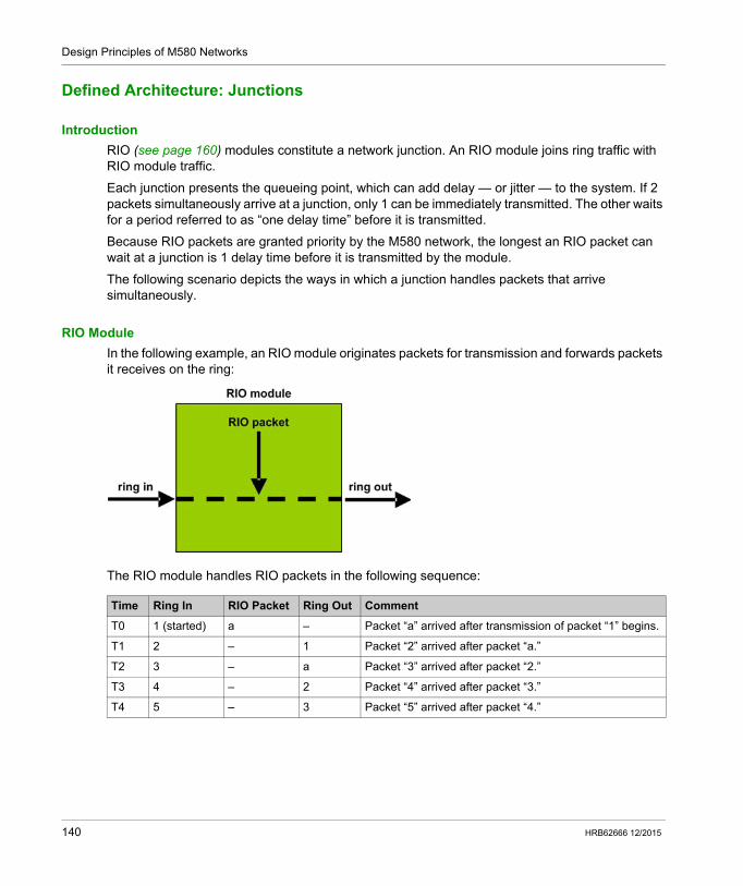
Design Principles of M580 Networks
Defined Architecture: Junctions
Introduction
RIO (see page 160) modules constitute a network junction. An RIO module joins ring traffic with RIO module traffic.
Each junction presents the queueing point, which can add delay — or jitter — to the system. If 2 packets simultaneously arrive at a junction, only 1 can be immediately transmitted. The other waits for a period referred to as “one delay time” before it is transmitted.
Because RIO packets are granted priority by the M580 network, the longest an RIO packet can wait at a junction is 1 delay time before it is transmitted by the module.
The following scenario depicts the ways in which a junction handles packets that arrive simultaneously.
RIO Module
In the following example, an RIO module originates packets for transmission and forwards packets it receives on the ring:
The RIO module handles RIO packets in the following sequence:
Time Ring In RIO Packet Ring Out Comment
T0 1 (started) a – Packet “a” arrived after transmission of packet “1” begins.
T1 2 – 1 Packet “2” arrived after packet “a.”
T2 3 – a Packet “3” arrived after packet “2.”
T3 4 – 2 Packet “4” arrived after packet “3.”
T4 5 – 3 Packet “5” arrived after packet “4.”
140 HRB62666 12/2015
Design Principles of M580 Networks
RIO with DIO Network Design Principles
Section C.3RIO with DIO Network Design Principles
Overview
This section describes the design principles for M580 network topologies that consist of a main ring with optional RIO and DIO sub-rings.
What Is in This Section?
This section contains the following topics:
Topic Page
RIO with DIO Network Design Principles 142
Defined Architecture: Topologies 143
RIO and DIO Defined Architecture: Junctions 145
HRB62666 12/2015 141
Design Principles of M580 Networks
RIO with DIO Network Design Principles
Overview
An M580 network can transmit data from distributed equipment. This is accomplished by using equipment that is configured to implement the following network design principles: CPU: CPU with Ethernet I/O scanner service on the local rack BMENOS0300 network option switch module Implementation of Defined Architectures: An M580 network supports the addition of DIO
data traffic only in specific network designs, including one of these: a main ring joined by a BMENOS0300 network option switch module to a DIO cloud a main ring with one or more RIO drops
These designs provide a limited number and type of junctions between network segments and a limited hop count from any device to the CPU.
QoS Traffic Prioritization: DIO packets are assigned the lower priority. They wait in a queue until a device finishes transmitting all RIO data packets. This limits RIO jitter to 128 µs, which represents the time required to complete the transmission of one DIO packet that has already begun.
DIO data is not delivered in real-time: DIO packets wait in a queue until all RIO packets are transmitted. DIO data transmissions use the network bandwidth that remains after RIO data has been delivered.
142 HRB62666 12/2015
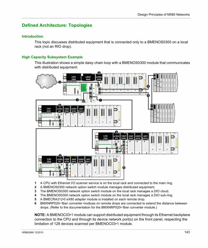
Design Principles of M580 Networks
Defined Architecture: Topologies
Introduction
This topic discusses distributed equipment that is connected only to a BMENOS0300 on a local rack (not an RIO drop).
High Capacity Subsystem Example
This illustration shows a simple daisy chain loop with a BMENOS0300 module that communicates with distributed equipment:
1 A CPU with Ethernet I/O scanner service is on the local rack and connected to the main ring.2 A BMENOS0300 network option switch module manages distributed equipment.3 The BMENOS0300 network option switch module on the local rack manages a DIO cloud.4 The BMENOS0300 network option switch module on the local rack manages a DIO sub-ring.5 A BMECRA312•0 eX80 adapter module is installed on each remote drop.6 BMXNRP020• fiber converter modlues on remote drops are connected to extend the distance between
drops. (Refer to the documentation for the BMXNRP020• fiber converter module.)
NOTE: A BMENOC03•1 module can support distributed equipment through its Ethernet backplane connection to the CPU and through its device network port(s) on the front panel, respecting the limitation of 128 devices scanned per BMENOC03•1 module.
HRB62666 12/2015 143
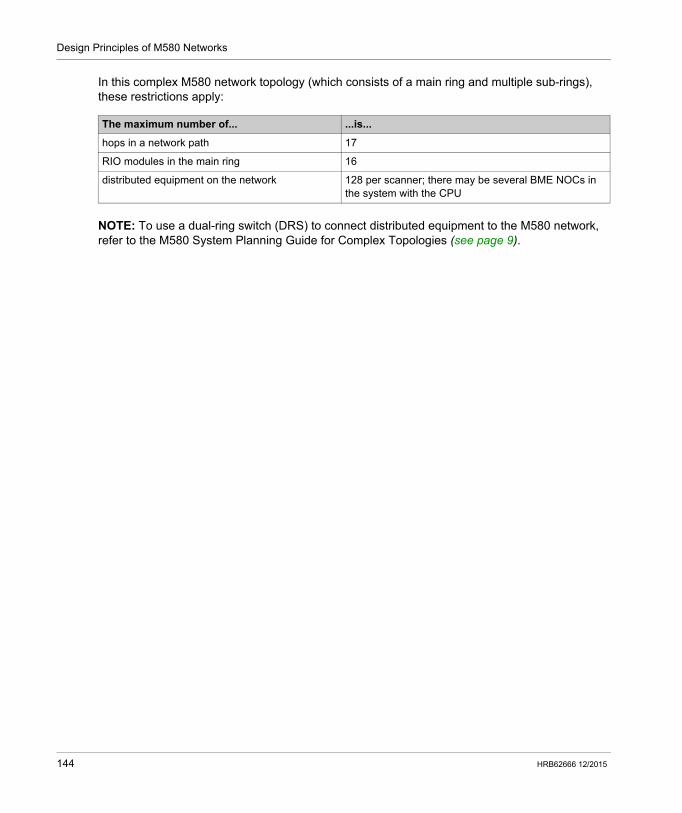
Design Principles of M580 Networks
In this complex M580 network topology (which consists of a main ring and multiple sub-rings), these restrictions apply:
NOTE: To use a dual-ring switch (DRS) to connect distributed equipment to the M580 network, refer to the M580 System Planning Guide for Complex Topologies (see page 9).
The maximum number of... ...is...
hops in a network path 17
RIO modules in the main ring 16
distributed equipment on the network 128 per scanner; there may be several BME NOCs in the system with the CPU
144 HRB62666 12/2015
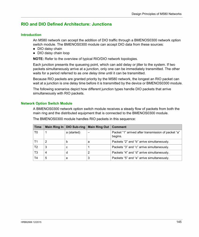
Design Principles of M580 Networks
RIO and DIO Defined Architecture: Junctions
Introduction
An M580 network can accept the addition of DIO traffic through a BMENOS0300 network option switch module. The BMENOS0300 module can accept DIO data from these sources: DIO daisy chain DIO daisy chain loop
NOTE: Refer to the overview of typical RIO/DIO network topologies.
Each junction presents the queueing point, which can add delay or jitter to the system. If two packets simultaneously arrive at a junction, only one can be immediately transmitted. The other waits for a period referred to as one delay time until it can be transmitted.
Because RIO packets are granted priority by the M580 network, the longest an RIO packet can wait at a junction is one delay time before it is transmitted by the device or BMENOS0300 module.
The following scenarios depict how different junction types handle DIO packets that arrive simultaneously with RIO packets.
Network Option Switch Module
A BMENOS0300 network option switch module receives a steady flow of packets from both the main ring and the distributed equipment that is connected to the BMENOS0300 module.
The BMENOS0300 module handles RIO packets in this sequence:
Time Main Ring In DIO Sub-ring Main Ring Out Comment
T0 1 a (started) – Packet “1” arrived after transmission of packet “a” begins.
T1 2 b a Packets “2” and “b” arrive simultaneously.
T2 3 c 1 Packets “3” and “c” arrive simultaneously.
T3 4 d 2 Packets “4” and “d” arrive simultaneously.
T4 5 e 3 Packets “5” and “e” arrive simultaneously.
HRB62666 12/2015 145

Design Principles of M580 Networks
146 HRB62666 12/2015
Modicon M580 Standalone
Glossary
HRB62666 12/2015
Glossary
!
%IAccording to the CEI standard, %I indicates a language object of type discrete IN.
%IWAccording to the CEI standard, %IW indicates a language object of type analog IN.
%MAccording to the CEI standard, %M indicates a language object of type memory bit.
%MWAccording to the CEI standard, %MW indicates a language object of type memory word.
%QAccording to the CEI standard, %Q indicates a language object of type discrete OUT.
%QWAccording to the CEI standard, %QW indicates a language object of type analog OUT.
%SWAccording to the CEI standard, %SW indicates a language object of type system word.
A
adapterAn adapter is the target of real-time I/O data connection requests from scanners. It cannot send or receive real-time I/O data unless it is configured to do so by a scanner, and it does not store or originate the data communications parameters necessary to establish the connection. An adapter accepts explicit message requests (connected and unconnected) from other devices.
advanced modeIn Unity Pro, advanced mode is a selection that displays expert-level configuration properties that help define Ethernet connections. Because these properties should be edited only by people with a good understanding of EtherNet/IP communication protocols, they can be hidden or displayed, depending upon the qualifications of the specific user.
architectureArchitecture describes a framework for the specification of a network that is constructed of these components: physical components and their functional organization and configuration operational principles and procedures data formats used in its operation
HRB62666 12/2015 147
Glossary
ARRAYAn ARRAY is a table containing elements of a single type. This is the syntax: ARRAY [<limits>] OF <Type>
Example: ARRAY [1..2] OF BOOL is a one-dimensional table with two elements of type BOOL.
ARRAY [1..10, 1..20] OF INT is a two-dimensional table with 10x20 elements of type INT.
ART(application response time) The time a CPU application takes to react to a given input. ART is measured from the time a physical signal in the CPU turns on and triggers a write command until the remote output turns on to signify that the data has been received.
AUXAn (AUX) task is an optional, periodic processor task that is run through its programming software. The AUX task is used to execute a part of the application requiring a low priority. This task is executed only if the MAST and FAST tasks have nothing to execute. The AUX task has two sections: IN: Inputs are copied to the IN section before execution of the AUX task. OUT: Outputs are copied to the OUT section after execution of the AUX task.
B
BCD(binary-coded decimal) Binary encoding of decimal numbers.
BOOL(boolean type) This is the basic data type in computing. A BOOL variable can have either of these values: 0 (FALSE) or 1 (TRUE).
A bit extracted from a word is of type BOOL, for example: %MW10.4.
BOOTP(bootstrap protocol) A UDP network protocol that can be used by a network client to automatically obtain an IP address from a server. The client identifies itself to the server using its MAC address. The server, which maintains a pre-configured table of client device MAC addresses and associated IP addresses, sends the client its defined IP address. The BOOTP service utilizes UDP ports 67 and 68.
broadcastA message sent to all devices in a broadcast domain.
C
CCOTF(change configuration on the fly) A feature of Unity Pro that allows a module hardware change in the system configuration while the system is operating. This change does not impact active operations.
148 HRB62666 12/2015
Glossary
CIP™(common industrial protocol) A comprehensive suite of messages and services for the collection of manufacturing automation applications (control, safety, synchronization, motion, configuration and information). CIP allows users to integrate these manufacturing applications with enterprise-level Ethernet networks and the internet. CIP is the core protocol of EtherNet/IP.
class 1 connectionA CIP transport class 1 connection used for I/O data transmission via implicit messaging between EtherNet/IP devices.
class 3 connectionA CIP transport class 3 connection used for explicit messaging between EtherNet/IP devices.
connected messagingIn EtherNet/IP, connected messaging uses a CIP connection for communication. A connected message is a logical relationship between two or more application objects on different nodes. The connection establishes a virtual circuit in advance for a particular purpose, such as frequent explicit messages or real-time I/O data transfers.
connectionA virtual circuit between two or more network devices, created prior to the transmission of data. After a connection is established, a series of data is transmitted over the same communication path, without the need to include routing information, including source and destination address, with each piece of data.
connection originatorThe EtherNet/IP network node that initiates a connection request for I/O data transfer or explicit messaging.
connectionlessDescribes communication between two network devices, whereby data is sent without prior arrangement between the two devices. Each piece of transmitted data also includes routing information, including source and destination address.
control networkAn Ethernet-based network containing PACs, SCADA systems, an NTP server, PCs, AMS, switches, etc. Two kinds of topologies are supported: flat: All modules and devices in this network belong to same subnet. 2 levels: The network is split into an operation network and an inter-controller network. These
two networks can be physically independent, but are generally linked by a routing device.
CPU(central processing unit) The CPU, also known as the processor or controller, is the brain of an industrial manufacturing process. It automates a process as opposed to relay control systems. CPUs are computers suited to survive the harsh conditions of an industrial environment.
HRB62666 12/2015 149
Glossary
D
DDT(derived data type) A derived data type is a set of elements with the same type (ARRAY) or with different types (structure).
determinismFor a defined application and architecture, you can predict that the delay between an event (change of value of an input) and the corresponding change of a controller output is a finite time t, smaller than the deadline required by your process.
Device DDT (DDDT)A Device DDT is a DDT predefined by the manufacturer and not modifiable by user. It contains the I/O language elements of an I/O module.
device networkAn Ethernet-based network within an RIO network that contains both RIO and distributed equipment. Devices connected on this network follow specific rules to allow RIO determinism.
DFB(derived function block) DFB types are function blocks that can be defined by the user in ST, IL, LD or FBD language.
Using these DFB types in an application makes it possible to:
simplify the design and entry of the program make the program easier to read make it easier to debug reduce the amount of code generated
DHCP(dynamic host configuration protocol) An extension of the BOOTP communications protocol that provides for the automatic assignment of IP addressing settings, including IP address, subnet mask, gateway IP address, and DNS server names. DHCP does not require the maintenance of a table identifying each network device. The client identifies itself to the DHCP server using either its MAC address, or a uniquely assigned device identifier. The DHCP service utilizes UDP ports 67 and 68.
DIO(distributed I/O) Legacy term for distributed equipment. DRSs use DIO ports to connect distributed equipment.
DIO cloudA group of distributed equipment that is not required to support RSTP. DIO clouds require only a single (non-ring) copper wire connection. They can be connected to some of the copper ports on DRSs, or they can be connected directly to the CPU or Ethernet communications modules in the local rack. DIO clouds cannot be connected to sub-rings.
150 HRB62666 12/2015
Glossary
DIO networkA network containing distributed equipment, in which I/O scanning is performed by a CPU with DIO scanner service on the local rack. DIO network traffic is delivered after RIO traffic, which takes priority in an RIO network.
distributed equipmentAny Ethernet device (Schneider Electric device, PC, servers, or third-party devices) that supports exchange with a CPU or other Ethernet I/O scanner service.
DNS(domain name server/service) A service that translates an alpha-numeric domain name into an IP address, the unique identifier of a device on the network.
domain nameAn alpha-numeric string that identifies a device on the internet, and which appears as the primary component of a web site’s uniform resource locator (URL). For example, the domain name schneider-electric.com is the primary component of the URL www.schneider-electric.com.
Each domain name is assigned as part of the domain name system, and is associated with an IP address.
Also called a host name.
DRS(dual-ring switch) A ConneXium extended managed switch that has been configured to operate on an Ethernet network. Predefined configuration files are provided by Schneider Electric to downloaded to a DRS to support the special features of the main ring / sub-ring architecture.
DSCP(differentiated service code points) This 6-bit field is in the header of an IP packet to classify and prioritize traffic.
DST(daylight saving time) DST is also called summer time and is a practice consisting of adjusting forward the clock near the start of spring and adjusting it backward near the start of autumn.
DT(date and time) The DT type, encoded in BCD in a 64-bit format, contains this information: the year encoded in a 16-bit field the month encoded in an 8-bit field the day encoded in an 8-bit field the time encoded in an 8-bit field the minutes encoded in an 8-bit field the seconds encoded in an 8-bit field
NOTE: The eight least significant bits are not used.
The DT type is entered in this format:
DT#<Year>-<Month>-<Day>-<Hour>:<Minutes>:<Seconds>
HRB62666 12/2015 151
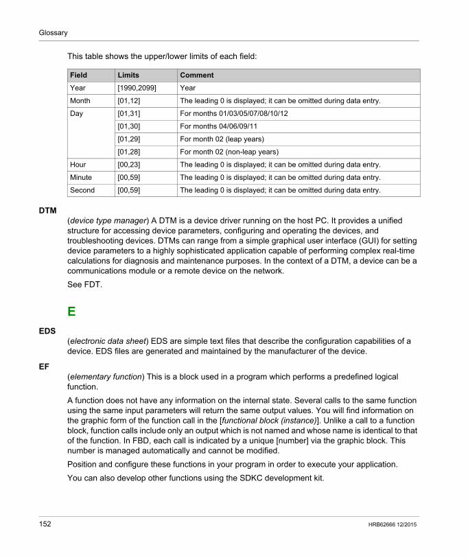
Glossary
This table shows the upper/lower limits of each field:
DTM(device type manager) A DTM is a device driver running on the host PC. It provides a unified structure for accessing device parameters, configuring and operating the devices, and troubleshooting devices. DTMs can range from a simple graphical user interface (GUI) for setting device parameters to a highly sophisticated application capable of performing complex real-time calculations for diagnosis and maintenance purposes. In the context of a DTM, a device can be a communications module or a remote device on the network.
See FDT.
E
EDS(electronic data sheet) EDS are simple text files that describe the configuration capabilities of a device. EDS files are generated and maintained by the manufacturer of the device.
EF(elementary function) This is a block used in a program which performs a predefined logical function.
A function does not have any information on the internal state. Several calls to the same function using the same input parameters will return the same output values. You will find information on the graphic form of the function call in the [functional block (instance)]. Unlike a call to a function block, function calls include only an output which is not named and whose name is identical to that of the function. In FBD, each call is indicated by a unique [number] via the graphic block. This number is managed automatically and cannot be modified.
Position and configure these functions in your program in order to execute your application.
You can also develop other functions using the SDKC development kit.
Field Limits Comment
Year [1990,2099] Year
Month [01,12] The leading 0 is displayed; it can be omitted during data entry.
Day [01,31] For months 01/03/05/07/08/10/12
[01,30] For months 04/06/09/11
[01,29] For month 02 (leap years)
[01,28] For month 02 (non-leap years)
Hour [00,23] The leading 0 is displayed; it can be omitted during data entry.
Minute [00,59] The leading 0 is displayed; it can be omitted during data entry.
Second [00,59] The leading 0 is displayed; it can be omitted during data entry.
152 HRB62666 12/2015
Glossary
EFB(elementary function block) This is a block used in a program which performs a predefined logical function.
EFBs have states and internal parameters. Even if the inputs are identical, the output values may differ. For example, a counter has an output indicating that the preselection value has been reached. This output is set to 1 when the current value is equal to the preselection value.
EIO networkEthernet I/O) An Ethernet-based network that contains three types of devices: local rack X80 EIO drop, or a Quantum EIO drop (using a BM•CRA312•0 adapter module), or a
BMENOS0300 network option switch module ConneXium extended dual-ring switch (DRS)
NOTE: Distributed equipment may also participate in an EIO network via connection to DRSs or the service port of X80 EIO adapter modules.
ENEN stands for ENable; it is an optional block input. When the EN input is enabled, an ENO output is set automatically.
If EN = 0, the block is not enabled; its internal program is not executed, and ENO is set to 0.
If EN = 1, the block's internal program is run and ENO is set to 1. If a runtime error is detected, ENO is set to 0.
If the EN input is not connected, it is set automatically to 1.
ENOENO stands for Error NOtification; this is the output associated with the optional input EN.
If ENO is set to 0 (either because EN = 0 or if a runtime error is detected): The status of the function block outputs remains the same as it was during the previous
scanning cycle that executed correctly. The output(s) of the function, as well as the procedures, are set to 0.
EthernetA 10 Mb/s, 100 Mb/s, or 1 Gb/s, CSMA/CD, frame-based LAN that can run over copper twisted pair or fiber optic cable, or wireless. The IEEE standard 802.3 defines the rules for configuring a wired Ethernet network; the IEEE standard 802.11 defines the rules for configuring a wireless Ethernet network. Common forms include 10BASE-T, 100BASE-TX, and 1000BASE-T, which can utilize category 5e copper twisted pair cables and RJ45 modular connectors.
Ethernet DIO scanner serviceThis embedded DIO scanner service of M580 CPUs manages distributed equipment on an M580 device network.
Ethernet I/O scanner serviceThis embedded Ethernet I/O scanner service of M580 CPUs manages distributed equipment and RIO drops on an M580 device network.
HRB62666 12/2015 153
Glossary
EtherNet/IP™A network communication protocol for industrial automation applications that combines the standard internet transmission protocols of TCP/IP and UDP with the application layer common industrial protocol (CIP) to support both high speed data exchange and industrial control. EtherNet/IP employs electronic data sheets (EDS) to classify each network device and its functionality.
explicit messagingTCP/IP-based messaging for Modbus TCP and EtherNet/IP. It is used for point-to-point, client/server messages that include both data, typically unscheduled information between a client and a server, and routing information. In EtherNet/IP, explicit messaging is considered class 3 type messaging, and can be connection-based or connectionless.
explicit messaging client(explicit messaging client class) The device class defined by the ODVA for EtherNet/IP nodes that only support explicit messaging as a client. HMI and SCADA systems are common examples of this device class.
F
FASTA FAST task is an optional, periodic processor task that identifies high priority, multiple scan requests, which is run through its programming software. A FAST task can schedule selected I/O modules to have their logic solved more than once per scan. The FAST task has two sections: IN: Inputs are copied to the IN section before execution of the FAST task. OUT: Outputs are copied to the OUT section after execution of the FAST task.
FBD(function block diagram) A graphical programming language that works like a flowchart. By adding simple logical blocks (AND, OR, etc.), each function or function block in the program is represented in this graphical format. For each block, the inputs are on the left and the outputs on the right. Block outputs can be linked to inputs of other blocks in order to create complex expressions.
FDR(fast device replacement) A service that uses configuration software to replace an inoperable product.
FDT(field device tool) The technology that harmonizes communication between field devices and the system host.
FTP(file transfer protocol) A protocol that copies a file from one host to another over a TCP/IP-based network, such as the internet. FTP uses a client-server architecture as well as separate control and data connections between the client and server.
154 HRB62666 12/2015
Glossary
full duplexThe ability of two networked devices to independently and simultaneously communicate with each other in both directions.
function block diagramSee FBD.
G
gatewayA gateway device interconnects two different networks, sometimes through different network protocols. When it connects networks based on different protocols, a gateway converts a datagram from one protocol stack into the other. When used to connect two IP-based networks, a gateway (also called a router) has two separate IP addresses, one on each network.
H
harsh environmentResistance to hydrocarbons, industrial oils, detergents and solder chips. Relative humidity up to 100%, saline atmosphere, significant temperature variations, operating temperature between -10°C and + 70°C, or in mobile installations. For hardened (H) devices, the relative humidity is up to 95% and the operating temperature is between -25°C and + 70°C.
HART(highway addressable remote transducer) A bi-directional communication protocol for sending and receiving digital information across analog wires between a control or monitoring system and smart devices.
HART is the global standard for providing data access between host systems and intelligent field instruments. A host can be any software application from a technician's hand-held device or laptop to a plant's process control, asset management, or other system using any control platform.
high-capacity daisy chain loopOften referred to as HCDL, a high-capacity daisy chain loop uses dual-ring switches (DRSs) to connect device sub-rings (containing RIO drops or distributed equipment) and/or DIO clouds to the Ethernet RIO network.
HMI(human machine interface) System that allows interaction between a human and a machine.
Hot StandbyA Hot Standby system uses a primary PAC (PLC) and a standby PAC. The two PAC racks have identical hardware and software configurations. The standby PAC monitors the current system status of the primary PAC. If the primary PAC becomes inoperable, high-availability control is maintained when the standby PLC takes control of the system.
HRB62666 12/2015 155
Glossary
HTTP(hypertext transfer protocol) A networking protocol for distributed and collaborative information systems. HTTP is the basis of data communication for the web.
I
I/O scannerAn Ethernet service that continuously polls I/O modules to collect data, status, event, and diagnostics information. This process monitors inputs and controls outputs. This service supports both RIO and DIO logic scanning.
IEC 61131-3International standard: programmable logic controllers
Part 3: programming languages
IGMP(internet group management protocol) This internet standard for multicasting allows a host to subscribe to a particular multicast group.
IL(instruction list) This language is a series of basic instructions. It is very close to assembly language used to program processors. Each instruction is made up of an instruction code and an operand.
implicit messagingUDP/IP-based class 1 connected messaging for EtherNet/IP. Implicit messaging maintains an open connection for the scheduled transfer of control data between a producer and consumer. Because an open connection is maintained, each message contains primarily data, without the overhead of object information, plus a connection identifier.
INT(INTeger) (encoded in 16 bits) The upper/lower limits are as follows: -(2 to the power of 15) to (2 to the power of 15) - 1.
Example: -32768, 32767, 2#1111110001001001, 16#9FA4.
inter-controller networkAn Ethernet-based network that is part of the control network, and provides data exchange between controllers and engineering tools (programming, asset management system (AMS)).
IODDT(input/output derived data type) A structured data type representing a module, or a channel of a CPU. Each application expert module possesses its own IODDTs.
IP addressThe 32-bit identifier, consisting of both a network address and a host address assigned to a device connected to a TCP/IP network.
156 HRB62666 12/2015
Glossary
IPsec(internet protocol security) An open set of protocol standards that make IP communication sessions private and secure for traffic between modules using IPsec, developed by the internet engineering task force (IETF). The IPsec authentication and encryption algorithms require user-defined cryptographic keys that process each communications packet in an IPsec session.
isolated DIO networkAn Ethernet-based network containing distributed equipment that does not participate in an RIO network.
L
LD(ladder diagram) A programming language that represents instructions to be executed as graphical diagrams very similar to electrical diagrams (contacts, coils, etc.).
literal value of an integerA literal value of an integer is used to enter integer values in the decimal system. Values may be preceded by the "+" and "-" signs. Underscore signs (_) separating numbers are not significant.
Example:
-12, 0, 123_456, +986
local rackAn M580 rack containing the CPU and a power supply. A local rack consists of one or two racks: the main rack and the extended rack, which belongs to the same family as the main rack. The extended rack is optional.
local slaveThe functionality offered by Schneider Electric EtherNet/IP communication modules that allows a scanner to take the role of an adapter. The local slave enables the module to publish data via implicit messaging connections. Local slave is typically used in peer-to-peer exchanges between PACs.
M
M580 Ethernet I/O deviceAn Ethernet device that provides automatic network recovery and deterministic RIO performance. The time it takes to resolve an RIO logic scan can be calculated, and the system can recover quickly from a communication disruption. M580 Ethernet I/O devices include: local rack (including a CPU with Ethernet I/O scanner service) RIO drop (including an Ethernet X80 EIO adapter module) DRS switch with a predefined configuraton
main ringThe main ring of an Ethernet RIO network. The ring contains RIO modules and a local rack (containing a CPU with Ethernet I/O scanner service) and a power supply module.
HRB62666 12/2015 157
Glossary
MASTA master (MAST) task is a deterministic processor task that is run through its programming software. The MAST task schedules the RIO module logic to be solved in every I/O scan. The MAST task has two sections: IN: Inputs are copied to the IN section before execution of the MAST task. OUT: Outputs are copied to the OUT section after execution of the MAST task.
MB/TCP(Modbus over TCP protocol) This is a Modbus variant used for communications over TCP/IP networks.
MIB(management information base) A virtual database used for managing the objects in a communications network. See SNMP.
ModbusModbus is an application layer messaging protocol. Modbus provides client and server communications between devices connected on different types of buses or networks. Modbus offers many services specified by function codes.
multicastA special form of broadcast where copies of the packet are delivered to only a specified subset of network destinations. Implicit messaging typically uses multicast format for communications in an EtherNet/IP network.
N
networkThere are two meanings: In a ladder diagram:
A network is a set of interconnected graphic elements. The scope of a network is local, concerning the organizational unit (section) of the program containing the network.
With expert communication modules:A network is a set of stations that intercommunicate. The term network is also used to define a group interconnected graphic elements. This group then makes up part of a program that may comprise a group of networks.
NIM(network interface module) A NIM resides in the first position on an STB island (leftmost on the physical setup). The NIM provides the interface between the I/O modules and the fieldbus master. It is the only module on the island that is fieldbus-dependent — a different NIM is available for each fieldbus.
NTP(network time protocol) Protocol for synchronizing computer system clocks. The protocol uses a jitter buffer to resist the effects of variable latency.
158 HRB62666 12/2015
Glossary
O
O->T(originator to target) See originator and target.
ODVA(Open DeviceNet Vendors Association) The ODVA supports network technologies that are based on CIP.
operation networkAn Ethernet-based network containing operator tools (SCADA, client PC, printers, batch tools, EMS, etc.). Controllers are connected directly or through routing of the inter-controller network. This network is part of the control network.
originatorIn EtherNet/IP, a device is considered the originator when it initiates a CIP connection for implicit or explicit messaging communications or when it initiates a message request for un-connected explicit messaging.
P
PACprogrammable automation controller. The PAC is the brain of an industrial manufacturing process. It automates a process as opposed to relay control systems. PACs are computers suited to survive the harsh conditions of an industrial environment.
port 502Port 502 of the TCP/IP stack is the well-known port that is reserved for Modbus TCP communications.
port mirroringIn this mode, data traffic that is related to the source port on a network switch is copied to another destination port. This allows a connected management tool to monitor and analyze the traffic.
Q
QoS(quality of service) The practice of assigning different priorities to traffic types for the purpose of regulating data flow on the network. In an industrial network, QoS is used to provide a predictable level of network performance.
HRB62666 12/2015 159
Glossary
R
rack optimized connectionData from multiple I/O modules are consolidated in a single data packet to be presented to the scanner in an implicit message in an EtherNet/IP network.
ready deviceEthernet ready device that provides additional services to the EtherNet/IP or Modbus module, such as: single parameter entry, bus editor declaration, system transfer, deterministic scanning capacity, alert message for modifications, and shared user rights between Unity Pro and the device DTM.
RIO dropOne of the three types of RIO modules in an Ethernet RIO network. A RIO drop is an M580 rack of I/O modules that are connected to an Ethernet RIO network and managed by an Ethernet RIO adapter module. A drop can be a single rack or a main rack with an extended rack.
RIO networkAn Ethernet-based network that contains 3 types of RIO devices: a local rack, an RIO drop, and a ConneXium extended dual-ring switch (DRS). Distributed equipment may also participate in an RIO network via connection to DRSs or BMENOS0300 network option switch modules.
RPI(requested packet interval) The time period between cyclic data transmissions requested by the scanner. EtherNet/IP devices publish data at the rate specified by the RPI assigned to them by the scanner, and they receive message requests from the scanner at each RPI.
RSTP(rapid spanning tree protocol) Allows a network design to include spare (redundant) links to provide automatic backup paths if an active link stops working, without the need for loops or manual enabling/disabling of backup links.
S
scannerA scanner acts as the originator of I/O connection requests for implicit messaging in EtherNet/IP, and message requests for Modbus TCP.
scanner class deviceA scanner class device is defined by the ODVA as an EtherNet/IP node capable of originating exchanges of I/O with other nodes in the network.
160 HRB62666 12/2015
Glossary
service portA dedicated Ethernet port on the M580 RIO modules. The port may support these major functions (depending on the module type): port mirroring: for diagnostic use access: for connecting HMI/Unity Pro/ConneXview to the CPU extended: to extend the device network to another subnet disabled: disables the port, no traffic is forwarded in this mode
SFC(sequential function chart) Used to graphically represent in a structured manner the operation of a sequential CPU. This graphical description of the CPU's sequential behavior and of the various resulting situations is created using simple graphic symbols.
SFP(small form-factor pluggable). The SFP transceiver acts as an interface between a module and fiber optic cables.
simple daisy chain loopOften referred to as SDCL, a simple daisy chain loop contains RIO modules only (no distributed equipment). This topology consists of a local rack (containing a CPU with Ethernet I/O scanner service), and one or more RIO drops (each drop containing an RIO adapter module).
SMTP(simple mail transfer protocol) An email notification service that allows controller-based projects to report alarms or events. The controller monitors the system and can automatically create an email message alert with data, alarms, and/or events. Mail recipients can be either local or remote.
SNMP(simple network management protocol) Protocol used in network management systems to monitor network-attached devices. The protocol is part of the internet protocol suite (IP) as defined by the internet engineering task force (IETF), which consists of network management guidelines, including an application layer protocol, a database schema, and a set of data objects.
SNTP(simple network time protocol) See NTP.
SOE(sequence of events) The process of determining the order of events in an industrial system and correlating those events to a real-time clock.
ST(structured text) The structured literal language is a developed language similar to computer programming languages. It can be used to organize a series of instructions.
sub-ringAn Ethernet-based network with a loop attached to the main ring, via a dual-ring switch (DRS) or BMENOS0300 network option switch module on the main ring. This network contains RIO or distributed equipment.
HRB62666 12/2015 161
Glossary
subnet maskThe 32-bit value used to hide (or mask) the network portion of the IP address and thereby reveal the host address of a device on a network using the IP protocol.
switchA multi-port device used to segment the network and limit the likelihood of collisions. Packets are filtered or forwarded based upon their source and destination addresses. Switches are capable of full-duplex operation and provide full network bandwidth to each port. A switch can have different input/output speeds (for example, 10, 100 or 1000Mbps). Switches are considered OSI layer 2 (data link layer) devices.
T
T->O(target to originator) See target and originator.
targetIn EtherNet/IP, a device is considered the target when it is the recipient of a connection request for implicit or explicit messaging communications, or when it is the recipient of a message request for un-connected explicit messaging.
TCP(transmission control protocol) A key protocol of the internet protocol suite that supports connection-oriented communications, by establishing the connection necessary to transmit an ordered sequence of data over the same communication path.
TCP/IPAlso known as internet protocol suite, TCP/IP is a collection of protocols used to conduct transactions on a network. The suite takes its name from two commonly used protocols: transmission control protocol and internet protocol. TCP/IP is a connection-oriented protocol that is used by Modbus TCP and EtherNet/IP for explicit messaging.
TFTP(trivial file transfer protocol) A simplified version of file transfer protocol (FTP), TFTP uses a client-server architecture to make connections between two devices. From a TFTP client, individual files can be uploaded to or downloaded from the server, using the user datagram protocol (UDP) for transporting data.
TIME_OF_DAYSee TOD.
162 HRB62666 12/2015
Glossary
TOD(time of day) The TOD type, encoded in BCD in a 32-bit format, contains this information: the hour encoded in an 8-bit field the minutes encoded in an 8-bit field the seconds encoded in an 8-bit field
NOTE: The eight least significant bits are not used.
The TOD type is entered in this format: xxxxxxxx: TOD#<Hour>:<Minutes>:<Seconds>
This table shows the upper/lower limits of each field:
Example: TOD#23:59:45.
TR(transparent ready) Web-enabled power distribution equipment, including medium- and low-voltage switch gear, switchboards, panel boards, motor control centers, and unit substations. Transparent Ready equipment allows you to access metering and equipment status from any PC on the network, using a standard web browser.
trapA trap is an event directed by an SNMP agent that indicates one of these events: A change has occurred in the status of an agent. An unauthorized SNMP manager device has attempted to get data from (or change data on) an
SNMP agent.
U
UDP(user datagram protocol) A transport layer protocol that supports connectionless communications. Applications running on networked nodes can use UDP to send datagrams to one another. Unlike TCP, UDP does not include preliminary communication to establish data paths or provide data ordering and checking. However, by avoiding the overhead required to provide these features, UDP is faster than TCP. UDP may be the preferred protocol for time-sensitive applications, where dropped datagrams are preferable to delayed datagrams. UDP is the primary transport for implicit messaging in EtherNet/IP.
UMAS(Unified Messaging Application Services) UMAS is a proprietary system protocol that manages communications between Unity Pro and a controller.
Field Limits Comment
Hour [00,23] The leading 0 is displayed; it can be omitted during data entry.
Minute [00,59] The leading 0 is displayed; it can be omitted during data entry.
Second [00,59] The leading 0 is displayed; it can be omitted during data entry.
HRB62666 12/2015 163
Glossary
UTC(coordinated universal time) Primary time standard used to regulate clocks and time worldwide (close to former GMT time standard).
V
variableMemory entity of type BOOL, WORD, DWORD, etc., whose contents can be modified by the program currently running.
VLAN(virtual local area network) A local area network (LAN) that extends beyond a single LAN to a group of LAN segments. A VLAN is a logical entity that is created and configured uniquely using applicable software.
164 HRB62666 12/2015
Modicon M580 Standalone
Index
HRB62666 12/2015
Index
Aadapter module
Ethernet RIO, 37application
starting, 109stopping, 109
application downloadfirst power up after, 107
application response time, 86, 89examples, 92optimizing, 94
applicationsdownloading to CPU, 104
architecture, 17sample, 83
ART, 86, 89examples, 92optimizing, 94
BBMENOS0300, 23BMX NRP 020•, 25BMX NRP 020•, 75BMXNGD0100
global data, 43
CCCOTF, 33cloud
DIO, 26commissioning
first power up after application download, 107power up CPU with Ethernet I/O scanner service, 103power up RIO adapter, 103
HRB62666 12/2015
communication loss detection, 96broken cable, 96RIO drop, 97
controllerselection, 59
CPUselection, 59
CPU applicationsdownloading, 104
DDATA_EXCH
error codes, 128determinism, 86, 89device network port, 36, 37
independent distributed I/O network, 63isolated DIO network, 62simple daisy chain loop, 66
diagnosticsdistributed equipment, 115main ring, 116RIO drops, 114RIO modules, 115RIO network, 113
DIO cloud, 26DIO network
independent, 63distributed equipment, 25, 48, 48distributed equipment diagnostics, 115downloading CPU applications, 104drop, 22
EEIO adapter module, 37Ethernet communication module, 36Ethernet distributed equipment network to-pology, 32Ethernet RIO drop, 22Ethernet RIO network maximum devices, 28
165
Index
Ethernet services, 33explicit messaging, 34
communication report, 131error codes, 128operation report, 131
FFDR, 107fiber converter module, 25, 75frequently asked questions, 119
Gglobal data
BMXNGD0100, 43
II/O memory, 81I/O modules, 40independent DIO network, 63isolated DIO network, 62isolation, 58
Llife cycle, 18, 53local rack, 20
Mmain ring diagnostics, 116MAST cycle time
calculating, 84
Nnetwork design examples, 139, 143network design principles
RIO networks, 138RIO with DIO networks, 142
network determinism parameters, 136
166
network topologyEthernet distributed equipment, 32Ethernet RIO network maximum devices, 28isolated DIO, 62planning, 54simple daisy chain loop, 65
NRP modulesconvert copper cable to fiber, 25, 75
Pport
device network, 36, 37, 62, 63, 66service/extend, 36, 37
power up CPU with Ethernet I/O scanner ser-vice, 103power up RIO adapter, 103powering modules
down, 108up, 108
Premium racks, 69programming
Unity Pro, 33
Rrack
local, 20racks
Premium, 69RIO and DIO defined architecture
junctions, 145RIO defined architecture
junctions, 140RIO drop, 22RIO drop diagnostics, 114RIO module diagnostics, 115RIO network diagnostics, 113rotary switches, 102RUN command, 107
Sservice/extend port, 36, 37
HRB62666 12/2015
Index
setting rotary switches, 102simple daisy chain loop
planning, 65software configuration, 33starting application, 109stopping application, 109system throughput, 82
Tthroughput, 82time stamping, 33
Wwarm restart, 108
XX80 EIO performance adapter module, 37X80 EIO standard adapter module, 37X80 I/O modules, 40
analog, 40discrete, 40intelligent, 43special purpose, 43
HRB62666 12/2015
167
Index
168
HRB62666 12/2015