Embed Size (px)
Citation preview
Department of mechatronics
Chair of Mechatronics systems
MHK70LT
Andrias Niklus
MODERNIZATION OF MILLING MACHINE DCS PRECIMILL M4
Master’s Thesis
Author applying for
master’s sciences of technical
academic degrees
Tallinn
2015
Milling machine DCS Precimill M4 modernization 2
AUTHOR'S DECLARATION
I hereby declare that this thesis is the result of my independent work.
On the basis of materials not previously applied for an academic degree.
All materials used in the work of other authors are provided with corresponding references.
The work was completed Mart Tamre guidance
“.......”....................2015 a.
The author
.............................. signature
The work meets the requirements for a master's work.
“.......”....................2015 a.
Supervisor
............................. signature
Permit to defense
................................. curriculum defence superior
“.......”....................2015 a.
............................. signature

Milling machine DCS Precimill M4 modernization 3
TUT Department of Mechatronics
Chair of Mechatronics Systems
MASTER’S THESIS SHEET OF TASK’S
Year 2015 semester 4
Student: Andrias Niklus, 082794
Curricula: Mechanics
Speciality: Mechatronics
Supervisor: Professor, Mart Tamre
Advisers: Rauno Luiv, CTO in Dental Export, 55603982
MASTER’S THESIS TOPIC: (in English) Modernization of milling machine DCS Precimill M4
(in Estonian) Freesmasina DCS Precimill moderniseerimine
Thesis tasks to be completed and the timetable:
Nr Description of tasks Timetable
1.
Milling machine DCS Precimill M4 dismounting, maintenance and
assembly
3. April
2.
Choosing new motor controllers and installing them. Connecting new
motor controllers with motors.
30. April
3.
Choosing new motors and installing them if necessary. Changing gears
if necessary.
30. April
4.
Choosing new CNC controlling software and installing it. 9. May
5.
Ensuring the work of the whole machine in order to use in
manufacturing process.
15. May
Solved engineering and economic problems:
Perform modernization of the milling machine DCS Precimill M4 as cheap as possible. Find
suitable hard- and software solutions and using these solution in practical work. Inspecting the
gears of the machine and improving them if necessary.
Additional comments and requirements:
Language: English
Application is filed not later than 04. May
Deadline for submitting the theses 22.05.2015
Student Andrias Niklus
Supervisor Mart Tamre
Confidentiality requirements and other conditions of the company are formulated as a company
official signed letter

Milling machine DCS Precimill M4 modernization 4
Table of Contents
MASTER’S THESIS SHEET OF TASK’S ............................................................................ 3
FOREWORD ............................................................................................................................ 6
EESSÕNA ................................................................................................................................. 7
1. INTRODUCTION ............................................................................................................. 8
2. MILLING MACHINES DISMOUNTING, MAINTENANCE AND ASSEMBLY ....... 10
2.1. Milling machines dismounting ............................................................................... 10
2.2. Milling machines maintenance .............................................................................. 11
2.3. Milling machines assembly .................................................................................... 12
3. CHANGING DCS PRECIMILL M4 BLOCK HOLDERS ........................................... 13
4. CHOOSING NEW MOTOR CONTROLLERS AND INSTALLING THEM.
CHANGING GEARS IF NECESSARY. .............................................................................. 15
4.1. Choosing new motor controllers ........................................................................... 15
4.2. Choosing additional devices ................................................................................. 16
4.3. Installing motor controllers ..................................................................................... 17
4.4. Changing gear where necessary .......................................................................... 18
5. CHOOSING NEW CNC CONTROL SOFTWARE ................................................... 19
6. DESIGNING THE NEW CONTROL SYSTEM .......................................................... 21
6.1. The main working order ......................................................................................... 21
6.2. Controlling axis movement .................................................................................... 23
6.2.1. DG4S-08020 axis amplifier connections ...................................................... 23
6.2.2. HDBB2 Break-out board and its connections ............................................. 26
6.2.3. UC-100 and its connections ........................................................................... 27
6.2.4. Differential line driver, its usage and connections ...................................... 28
6.3. Tool changing process ........................................................................................... 29
6.3.1. The main idea of tool changing process ...................................................... 30
6.3.2. Devices used for tool changing process ...................................................... 32
Milling machine DCS Precimill M4 modernization 5
6.3.3. Arduino UNO connections .............................................................................. 33
6.3.4. The logic of choosing the right tool ............................................................... 35
6.4. Electrical changes and solutions .......................................................................... 37
6.4.1. Devices controlled by relays and contactors ............................................... 38
6.5. Block holding system for glass-ceramics ............................................................ 39
6.6. G-code and changing it .......................................................................................... 40
7. COST CALCULATIONS ............................................................................................... 42
8. SUMMARY ..................................................................................................................... 43
8. KOKKUVÕTE ................................................................................................................. 45
9. REFERENCES ............................................................................................................... 47
EXTRAS .................................................................................................................................. 48
E1 Milling machine DCS Precimill M4 ............................................................................ 48
E2 Milling machine Wieland iMes-750i .......................................................................... 49
E3 Simplifying schemes about electronic devices of the milling machine ................ 50
E4 Greasing nozzle’s thread transition drawing ........................................................... 53
E5 DG4S-08020 picture ................................................................................................... 54
E6 HDBB2 Break-out Board ............................................................................................ 55
E7 HDBB2 Centronics 36 cable connections ................................................................ 56
E8 HDBB2 Break-out board screw terminal connections ........................................... 57
E9 UC-100 Motion Controller ........................................................................................... 58
E10 Differential Line Driver .............................................................................................. 59
E11 Arduino UNO .............................................................................................................. 60
E12 Relay Module ............................................................................................................. 61
E13 Arduino UNO and Relay Shield’s connections ..................................................... 62
E14 Existing voltage raising scheme .............................................................................. 63

Milling machine DCS Precimill M4 modernization 6
FOREWORD
The master’s thesis topic was chosen in collaboration with Rauno Luiv who is the CTO in a
company called “Dental Export”. He wanted to add old milling machine DCS Precimill M4
back to production. During the modernization of the machine, people involved considered many
various modernization levels. Taking in consideration that the assignment was practical the
author ran in to many various problems that would not occur during theoretical work. The main
setback was the time needed for completion of the work.
Hereby the author would like to thank master’s thesis supervisor Mart Tamre for his support
and enterprise Dental Export worker Rauno Luiv for many discussions and for the trust.

Milling machine DCS Precimill M4 modernization 7
EESSÕNA
Magistritöö teema valiti koostöös ettevõtte „Dental Export“ töötaja Rauno Luiviga, kes avaldas
soovi freesmasin DCS Precimill M4 uuesti tootmisse rakendada. Töö teostamise ajal kaaluti
jooksvalt moderniseerimisega seoses erinevaid uuenduse astmeid. Arvestades asjaolu, et
tegemist on praktilise ülesandega tekkis töös ka hulgaliselt tõrkeid ning teostamise ajakulu
kujunes algselt planeeritust palju suuremaks.
Siinkohal soovib auto tänada magistritöö juhendajat Mart Tamret tema toetuse eest ja ettevõtte
Dental Export tehnilist juhti Rauno Luivi usalduse ja nõuannete eest.

Milling machine DCS Precimill M4 modernization 8
1. INTRODUCTION
The master’s degree thesis was collaborated with the company called Dental Design that was
founded in 2010 and is specialised to producing good quality artificial teeth. The task was to
involve old milling machine DCS Precimill M4 to production. (Extra 1) The milling machine
is specially built for producing artificial teeth. DCS Precimill M4 was removed from production
when company bought new milling machine Wieland iMes-750. (Extra 2) Taking into
consideration that the technology of producing teeth had involved a lot during that time the old
machine was just left to collect dust. The demand for artificial teeth has increased lately and
one milling machine could not satisfy the need for production output, so the old machine will
be re-established to production.
The difference between those two machines is immense. The iMes milling machine uses round
milling blocks and is capable of milling following materials: BruxZir (not sintered), zirconia
(not sintered), wax, PMMA, cobalt-chrome, titan and e-max. The older machine used
rectangular milling blocks and was used to mill sintered zirconia and titanium. Milling sintered
zirconia is inefficient and therefore it is not milled anymore. According to recent plans the DCS
Precimill M4 will be used to mill titanium, cobalt-chrome and e-max as all of these materials
need usage of cooling liquid. Thanks to that solution the newer milling machine form iMes will
stay cleaner and will need less service.
The aim of this work is to modernize the old milling machine DCS Precimill M4 and take it
into use. This machine was in use during the company’s early years and was replaced with the
new one because it’s amortisation. Now, when demand for artificial teeth has grown
significantly the company had to find a way how to increase production. And the best way to
do this is to take into use the existing machine that requires modernization. During the master’s
degree thesis the author will introduce several problems that occurred during modernization
process and introduces solutions how these complications can be solved.
The master’s thesis is divided into six sections. First paragraph introduces milling machines
dismounting, maintenance and assembly. In this part the author will describe the performing of
the aforementioned activities and the problems that turned out during that process. The toughest
set-back from this chapter was bearings greasing process that finally got quite simple solution.
Milling machine DCS Precimill M4 modernization 9
Second paragraph is focused on the machine’s block holder exchange process. The positive and
negative sides of this process have been brought out and finally the decision whether it is even
reasonable to change the squared block holder for the round one or not.
In the third paragraph the author explains how the new axis amplifiers were chosen. All the
additional devices that were needed for the installation of the axis amplifiers are brought out as
well. In this paragraph the author also brings out fact if the gears were changed and how was
this process carried out.
The fourth chapter is concentrated on choosing the new CNC control software. In this chapter
the author compares different software providers and finally makes a well-considered decision
on what kind of software to use.
The fifth paragraph turned out to be hardest one as the author finds out that the plans on how to
make the machine work are going to fail as the machine parts are too integrated. In this chapter
a new control system is designed with all the necessary features. In the beginning of this
paragraph the author explains how to connect all the devices that were chosen in the previous
chapter. Then the all new tool changing process is worked out that as it turns out needs an extra
controller. After that some of the electrical solutions are explained as some of the old parts can
be used. Later on the changes with block holding system come up again as the grinding process
for glass-ceramics needs special solution. In the end of that chapter the author explains what
kind of changes have to be done in G-code in order to use the code calculated for the new
machine.
The sixth and final chapter is for cost calculations where the author brings out all the purchases
that were made and also the ones that still have to be made.
All of the development is carried out keeping in mind the requests from the company. Different
levels of renewals were discussed and the choice was made mainly considering the project cost.
During the work some initial ideas were changed due to various reasons. All of the changes
made during the process are described in the work.

Milling machine DCS Precimill M4 modernization 10
2. MILLING MACHINES DISMOUNTING, MAINTENANCE AND
ASSEMBLY
2.1. Milling machines dismounting
Milling machines dismounting was carried out due to necessity of machines maintenance.
Considering the fact that no drawings nor paperwork about the machines mechanical
construction were owned a lot of pictures were taken during the dismounting process. Drawings
for some of the electrical connections were sent from the manufacturer but as they were
incomplete, photos of electrical connections were also taken for precaution. For electrical
connections simplified schemes were made using Google Sketch Up software. (Extra 3) The
dismounting process was performed using the logic to dismount as little as possible but as much
as necessary to carry out maintenance. In the early stages of the dismounting were noticed that
the required grease level on some parts was sufficient as other parts clearly needed lubrication.
The dismounting took two days to complete not considering electrical connections inside the
machine. There was no point of disconnecting anything as long as the new motor controllers
had not been chosen. The main obstacle during the dismounting process was lifting the milling
part from the body, as the weight of the milling part is about hundred kilograms.
The dismounting was carried out as follows:
1) Dismounting the exterior body from the machine which was necessary to even get close
to the rest of the machine.
2) Unlinking the pneumatic hoses from the milling part of the machine. Otherwise it would
not have been possible to separate the milling part of the machine from machines body.
3) Unlinking electrical cables that were outside of the machine. Most of the cables had
connection plugs outside of the body so it was only necessary to mark the plugs and
disconnect them. Some of the components like end-switches and controller next to the
machine did not have plugs so the disconnections had to be made directly from the
device where there were many wires. Simplified schemes of the connections are shown
in Extra 3.

Milling machine DCS Precimill M4 modernization 11
4) Removing the milling part of the machine from the body. The milling part is connected
to the body with only three bolts but as the part weighs about hundred it was difficult to
remove it as no necessary tools were to be found. Finally the part was removed using
manpower of two men, where one of them really hurt his back. Therefore a better plan
had to be created in order to mount it back later.
5) Removal of the hinge covers was the last necessary part of dismounting in order to start
maintenance.
2.2. Milling machines maintenance
The main purposes of the maintenance were cleaning the machine and greasing the moving
parts. Maintenance was carried out during the dismounting and immediately after. Removed
body covers were cleaned using Loctite 7010 which is specially designed to clean manufacture
machines. While trying to grease the bearings of the machine first big problem was discovered.
Special kind of oiling nipples were used in the machine. After long research on the web and
many calls to different greasing equipment sellers in Estonia it was realised that no special
greasing nozzle was to be found. Changing the grease did not require high pressure so as a last
resort using syringe was tried but no success was achieved. Therefore it was decided to produce
a special part in order to use standard oiling nozzles. Original nozzles were attached to the
machine with M4 thread and the smallest nozzles available in stores used M6 thread. In order
to change the greasing a transition from M4 external to M6 internal thread was needed. First a
drawing of the part was made (Extra 4). Producing that kind of detail is not difficult but
companies are not interested in producing one little detail and therefore the price is really high
for just one piece. First it was tried to mill the detail with iMes milling machine but CAM
software had trouble calculating it with through hole. So the hole was closed on one side as you
can see in the drawing. Only two metal materials were to be chosen: cobalt-chrome and
titanium. The detail was milled from cobalt-chrome as it is easier to process it in following
phases. Unfortunately the milling machine was not able to mill eight millimetres of the hole.
Post-processing was done by using diamond grinding blades for hand milling machine. After
breaking two blades it was realised that the material was too tough to get hole through it. The
final solution was made from copper by one of the workers from the company who had a lathe
at home. Lastly a rubber seal was added to the detail to ensure a hermetic connection. Using
this detail it was possible to grease the bearings of the axis.

Milling machine DCS Precimill M4 modernization 12
2.3. Milling machines assembly
Milling machines assembly was made in a way that it was assembled before. Author’s drawings
and simplified schemes (Extra 3) were used to do that. It was told that some of the end-switches
are not working correctly and as for primary inspection their connections were checked. It
turned out that one of the end-switches was connected differently from the other. More thorough
inspection was carried out in subsequent phases where it also turned out that one of the end-
switches had a mechanical defect. The connection between contacts did not change whether the
button of the switch was pushed down or not. It was decided to order a new end-switch after
the tests of the machine are finished.

Milling machine DCS Precimill M4 modernization 13
3. CHANGING DCS PRECIMILL M4 BLOCK HOLDERS
Companies newer milling machine iMes 750i uses round milling blocks but DCS Precimill M4
uses rectangular blocks. It was considered to start using round blocks on DCS machine to make
managing the storage a lot easier. Firstly it was necessary to know how hard it would be to
make that kind of change in the machine. The change will be performed if it does not cost too
much and is easy to make. Block holder is attached to the machine in a way that its distance
can be changed using spacers but we have to make sure that there is enough space for cutter.
The machines dimensions were measured and it turned out that there will not be enough space
for cutter. The result is easier to understand from the Drawing 1.
Drawing 1. Explanatory drawing about changing the block holder

Milling machine DCS Precimill M4 modernization 14
On the drawing the round block holder is shown on maximum distance. The blocks have to be
able to make 180 degree turn and that is how the measuring has been made. If the block holder
is able to make 180 degree turn we cannot mill material with thickness of 25 millimetres which
is necessary requirement. It is shown on the drawing that the distance between block holder
centre and cutter is 9 millimetres, but in order to mill 25 millimetres thick block it has to be at
least 15 millimetres. Considering the fact that it is necessary to change the position of the cutter
to use round blocks the idea for doing that was dismissed as it would have been costly and
complicated. This idea will be considered in the future.

Milling machine DCS Precimill M4 modernization 15
4. CHOOSING NEW MOTOR CONTROLLERS AND
INSTALLING THEM. CHANGING GEARS IF NECESSARY.
4.1. Choosing new motor controllers
The choice of new motor controllers was mostly based on motors current and voltage indicators.
Furthermore it was considered important that the controller would connect easily with other
devices and the connection between computer and controller would be described
understandably. Two controllers were selected out as main options: DG4S-08020 from CNC
Drive production [1] and Gecko G320X. [2] Main indicators of the two chosen controllers are
quite similar. DG4S-08020 controller does have twice as big input signal frequency, in addition
it does support motors with lower voltage. The price is also a little bit lower for DG4S-08020.
Gecko G320X has better working temperature range though. Considering the fact that the
working temperature should not rise over 30 degrees Celsius.
Table 1. Table to compare motor controllers
DG4S-08020 Gecko G320X
Motor voltage
[VDC]
Minimum Maximum Minimum Maximum
12 80 18 80
Motor current [A] 0 20 0 20
Working
temperature [°C] 0 65 0 70
Input signal
frequency [kHz] 0 400 0 200
Price [€] 80 112
According to table 1 DG4S-08020 controllers were chosen. The key feature why it was chosen
was the fact that the additional devices to these controllers were easy to find on the same
webpage. The support of CNC Drive was also spectacular.
Milling machine DCS Precimill M4 modernization 16
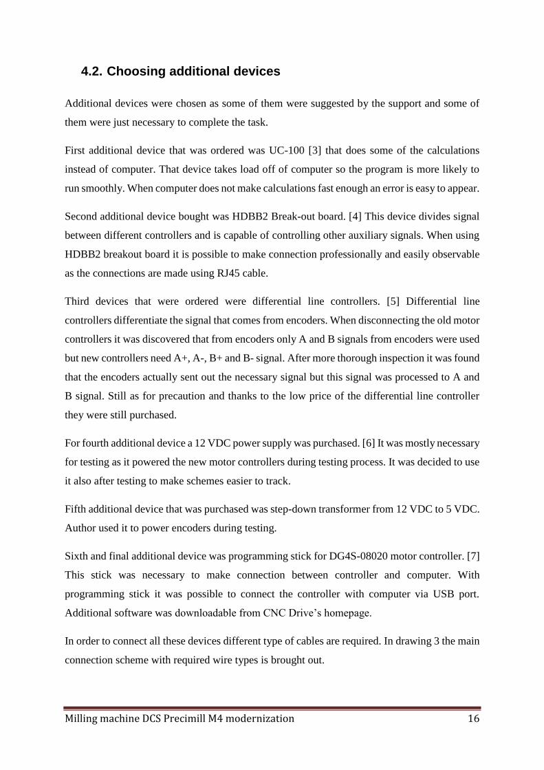
4.2. Choosing additional devices
Additional devices were chosen as some of them were suggested by the support and some of
them were just necessary to complete the task.
First additional device that was ordered was UC-100 [3] that does some of the calculations
instead of computer. That device takes load off of computer so the program is more likely to
run smoothly. When computer does not make calculations fast enough an error is easy to appear.
Second additional device bought was HDBB2 Break-out board. [4] This device divides signal
between different controllers and is capable of controlling other auxiliary signals. When using
HDBB2 breakout board it is possible to make connection professionally and easily observable
as the connections are made using RJ45 cable.
Third devices that were ordered were differential line controllers. [5] Differential line
controllers differentiate the signal that comes from encoders. When disconnecting the old motor
controllers it was discovered that from encoders only A and B signals from encoders were used
but new controllers need A+, A-, B+ and B- signal. After more thorough inspection it was found
that the encoders actually sent out the necessary signal but this signal was processed to A and
B signal. Still as for precaution and thanks to the low price of the differential line controller
they were still purchased.
For fourth additional device a 12 VDC power supply was purchased. [6] It was mostly necessary
for testing as it powered the new motor controllers during testing process. It was decided to use
it also after testing to make schemes easier to track.
Fifth additional device that was purchased was step-down transformer from 12 VDC to 5 VDC.
Author used it to power encoders during testing.
Sixth and final additional device was programming stick for DG4S-08020 motor controller. [7]
This stick was necessary to make connection between controller and computer. With
programming stick it was possible to connect the controller with computer via USB port.
Additional software was downloadable from CNC Drive’s homepage.
In order to connect all these devices different type of cables are required. In drawing 3 the main
connection scheme with required wire types is brought out.

Milling machine DCS Precimill M4 modernization 17
Drawing 2. Connections between devices on block scheme
4.3. Installing motor controllers
The installation of the motor controllers turned out to be a lot harder than it was expected.
Firstly to start programming the controller it was tested to provide digital power to controller
but computer could not connect to device with only digital powered applied to it. After that
digital power and five volts to encoder input was provided but computer was still not able to
connect to the controller. It turned out that in order to start programming the motor controller
had to be already correctly connected to the machine. When connecting the encoder with
differential line controller another problem appeared. The encoder signal game from terminals
and it was processed by special processor that was integrated with the old computer. As the old
computer did not work anymore it became apparent that the encoder A and B signals could not
be taken from the same terminals they were taken before. Therefore the author decided to
connect encoders taking signal straight from encoders. The encoders give out signals with six
wires plus they have two wires to power the encoder. In the drawings that were given from
support about the encoder signals the wire colours did not match. The author presumed that the
connection numbers to the terminals were correct but once the author connected the encoder,
error about encoder signals appeared on the controllers LED indicators. After that voltages

Milling machine DCS Precimill M4 modernization 18
between encoder wires were measured and voltages between two different pairs of wires were
established. The encoders used with the machine do not have any recognition signs on them so
the author had to anticipate that the signals with voltage between them were the correct ones.
When connecting the controllers with encoder signals that the author chose no error was
discovered by the controller. The computer unfortunately was still unable to connect to the
controller. It managed to update the software in the controller though. In order to move forward
the author had make test the encoders to be sure about its outputs that should be as follows:
1) A channel -
2) A channel +
3) B channel -
4) B channel +
5) Index –
6) Index +
7) 5 VDC
8) GND
After this problem occurred the hole controlling system was examined and it turned out that all
the procedures are controlled by computer not by controllers and electrical schemes as it was
assumed. With this new information and considering the fact that the old computer does not
work it was decided that it would be easier to design new controlling system from the scratch
than to try to restore the old one. Therefore the plans took a huge turn and the author decided
to design a new controlling system to machine as a master’s thesis and to build the machine
after the controlling system’s design is complete.
4.4. Changing gear where necessary
The motors control the axis by spinning the threaded rods. The force from the motors shaft is
transferred to threaded rod by rubber belt. The machine worked with spectacular accuracy with
these gears and therefore it was decided not to do any radical changes to them. All the rubber
belts were inspected and it was decided that all of them are in good condition. Therefore all of
the rubber belts were tightened and the bearings were already greased in the maintenance phase.
No other changes were necessary.

Milling machine DCS Precimill M4 modernization 19
5. CHOOSING NEW CNC CONTROL SOFTWARE
When choosing new CNC control software the author based on the fact that it had to be cheap,
reliable, easy to understand and easy to connect to other devices. All the parts were ordered
from CNCdrive Motion Control and therefore the first choice of the software game from the
same site. The site offered software called UCCNC that should be able to control up to 6-axis.
[8] It is able to execute G-code that is also necessary and is it originates from the same place as
the ordered parts it is definitely compatible with other devices.
Another software that was brought out on the same webpage is Mach3. [9] Mach3 is also
compatible with ordered devices and especially with UC100. When comparing Mach3 and
UCCNC it was soon noticed that Mach3 is much more opened system that supports a lot of
plugins and is more configurable. After researching feedback from other users it became clear
that Mach3 is a better choice because of its configurability.
When the author had decided to use Mach software another choice had to be made because a
new version Mach4 had been released. The newer version should probably be better but it does
not have all the extra plugins yet as the Mach3 has. Fortunately both of these programs had free
demo version downloads. The author downloaded both of these programs for testing.
While comparing these programs it seemed that Mach4 is better. It was easier to find all the
necessary input and output visualisations, it had much better graphics and all the extra functions
were simpler to find. Mach3 on the other hand seemed a bit out-dated. It had quite bad graphic
and most of the extra functions were more clicks away. The older version did have its perks as
well. First of all it was trustworthy as it has a lot of satisfied users. Secondly there is a lot more
information available online for debugging any errors that might occur. Finally it was a little
bit cheaper than the newer version.
After almost choosing the new Mach4 version a sad fact turned out as the author suspected. The
UC100 motion controller plugin was only available for the old Mach3 version. Therefore it
became clear that Mach3 software will be used for the project.

Milling machine DCS Precimill M4 modernization 20
During the process a comparative table was made to make decision-making easier.
Table 2. Comparative table for choosing the new CNC control software
Program UCCNC Mach3 Mach4
Control at least 4 axis Yes Yes Yes
Able to execute G-code Yes Yes Yes
Compatible with UC-100 Yes Yes No
Widely used/lot of information
available online No Yes Not yet
Supports many add-ons No Yes Not yet
Price [€] 45 215 200
According to the table 2 and explanations give before the Mach3 seems rational choice to be
made. It is the most expensive program according to the table but the price in the table is
calculated with the UC-100 Add-on. UCCNC has it integrated and Mach4 does not support it
yet.
The program will be purchased only after the testing is done and machine is ready to be put into
manufacturing process.
Milling machine DCS Precimill M4 modernization 21
6. DESIGNING THE NEW CONTROL SYSTEM
It was explained that the old control system was very integrated to its host computer. Almost
all the calculations were done through its computer and the computer had special controllers
attached to it. The controllers were connected to the motherboard via ribbon cable and no
information about these connections were to be found. As a result it was decided to design a
new control system from the scratch. It will be a very long process to get the machine working
but it was evaluated as the easier way of getting it done.
6.1. The main working order
It was very important to start with building up the main idea of how the machine is going to
work. In order to do that an explanatory block scheme was drawn. The whole system became
big as all the features had to be considered. On the block scheme (Drawing 3, page 18) is shown
the main idea of the controlling process. The main application that the system does is to move
axis. In order to move axis the system needs feedback from axis position. Therefore the signal
has to go to the axis and the feedback is taken from encoders. Other features also have to be
controlled, such as: emulsion pump work, spindle work and tool height has to be measured and
considered during manufacturing process. Fortunately the Mach3 software already has built in
such features as measuring tool height and controlling if the spindle is rotating.
When drawing a block scheme it became obvious that the whole system will not fit on one
scheme to explain it thoroughly. For example a tool check was entirely left out from the main
process drawing. Therefore other schemes were drawn in order to explain different steps of the
process.

Milling machine DCS Precimill M4 modernization 22
Drawing 3. Explanatory drawing of the main controlling system

Milling machine DCS Precimill M4 modernization 23
6.2. Controlling axis movement
The main task of the machine controlling is obviously controlling the axis movement. The
machine will be working with four moveable axis. X-, Y- and Z-axis have linear movement and
the A-axis has rotary movement. The newer machine iMes 750i that is used in the
manufacturing process does have similar axis movement. The iMes does have a fifth C-axis
rotary movement that DCS Precimill M4 does not have. The C-axis movement can be disabled
on the CAM software and as the company wants to use the same CAM software on both
machines it is an important feature.
All of the axis (four of them) are controlled by DG4S-08020 axis amplifiers. (Extra 5)
DG4S-08020 has five different connectors:
1) Power in connector
2) Motor connector
3) USB connector
4) Main connector
5) Encoder connector
In working order four of those connectors must be connected. The USB connector is used only
in programming phase.
6.2.1. DG4S-08020 axis amplifier connections
It was mentioned in the previous chapter that DG4S-08020 has five connectors: Power in,
Motor, USB, Main and Encoder. The axis amplifier’s connections are connected as follows
(also see extra 6):
X-, Y- and Z-axis amplifiers Power in connections are connected to the 56 VDC power supply
for the motors. 56 VDC power supply voltage comes from the 230 VAC to 40 VDC power
transformer that has existing electrical scheme after it. Motor connectors are connected directly
to motor. Arm 1 is connected to motor plus terminal and Arm 2 is connected to motor minus
terminal. USB connector is used only for programming the device. It connects with
programming stick through four pin connector. Main connector connections are made with
RJ45 plug that has eight wires.

Milling machine DCS Precimill M4 modernization 24
The wires inside RJ45 have to be connected as follows:
1) Step signal input
2) Direction signal input
3) Ground for Step and Direction signals
4) 5 VDC power input (only used when 12 VDC is not
applied)
5) Reset (input) and Stop (input)
6) Error (output) and Stop input
7) DC power + (12 VDC input for digital power)
8) DC power – (ground for the 12 VDC power supply)
This kind of connections are gotten from HDBB2 break-out board. The board does not give out
any signal on pin four as required from the DG4S-08020 manual. The signal to the board comes
from UC100 motion controller that gets its signal from the computer.
Encoder signal is also gotten using RJ45 plug. The pinout for the Encoder signal is as follows:
1) GND
2) 5 VDC
3) Index +
4) Index –
5) A channel +
6) A channel –
7) B channel +
8) B channel –
CNCdrive. As there is no information about the encoders that are installed on the machine these
signals will be first connected during testing period.
The connections to the X-, Y- and Z-axis amplifiers are shown on the drawing 4. For the A-
axis amplifier the only difference is power in voltage. A-axis amplifier gets 24 VDC to its
Power in connector straight from the 230 VAC to 24 VDC power transformer.

Milling machine DCS Precimill M4 modernization 25
Drawing 4. The connections to the X-, Y- and Z-axis amplifiers

Milling machine DCS Precimill M4 modernization 26
6.2.2. HDBB2 Break-out board and its connections
The break-out board’s (Picture shown in Extra 6) main task is to divide signal between different
axis amplifiers. It has main input that is connected with Centronics 36 cable and four main RJ45
outputs for axis amplifiers. It has five extra inputs and outputs, power input for 12 VDC supply,
Reset input and Error input and output. All-in-all it has 38 extra screw terminals in addition to
plug connections. The Centronics cable gets signal from UC100 that has DSUB-25(LPT) plug,
so standard transformation cable is used in order to transfer these signals. The plugs pinouts are
shown in Extra 7. The RJ45 pinout signals are as follows:
1) Step signal
2) Direction signal
3) LPT port ground
4) N/C (no internal connection)
5) Reset signal
6) Common Error line
7) 12 VDC power output +
8) 12 VDC power output –
This kind of output is compatible with DG4S-08020 Main input and makes it easier to connect
these two devices.
The pinout for screw terminals are shown in Extra 8.
The HDBB2 Break-out board is used as the main unit for controlling the work of the whole
machine because it is easily connectable to the computer and its signals can be controlled and
programmed in the Mach3 software. Only tool change progress needs its own controller, all
other devices will work through the Break-out board. The tool changer controller will still get
its start signal from the board and will notify the board when it is done. The main connections
of the Break-out board are shown in the drawing 5.

Milling machine DCS Precimill M4 modernization 27
Drawing 5. Simplified scheme for connecting HDBB2 Break-out board
6.2.3. UC-100 and its connections
The UC-100 Motion Controller (Picture is shown in Extra 9) is used to decrease the amount of
calculations that the controlling computer has to do. Some of the calculations are made in UC-
100 instead of the computer. The use of UC-100 is important because if there are any delay of
signal coming from the computer it will corrupt the controlling system. Using UC-100 evidently
decreases that risk. UC-100 is connected to the computer via mini-USB to USB cable. The other
plug is connected to the HDBB2 Break-out board via DSUB-25 to Centroncs 36 cable. Mach3
CNC control software that is used has a plugin for UC-100 Motion Controller and that makes
it easy to use.

Milling machine DCS Precimill M4 modernization 28
6.2.4. Differential line driver, its usage and connections
Differential line driver was used to differentiate the signal that comes from the encoders (Picture
of the driver is shown in Extra 10). This device is only necessary when encoders with signals
outputs A and B are used. If encoders send out A+, A-, B+, B- signals then differential line
drivers are not needed. Differential line drivers have screw terminals for input wires and RJ45
plug to send signal out. Differential line driver input signals are the following:
1) GND
2) A channel
3) 5 VDC
4) B channel
Differential line driver’s output signals are the following:
1) GND
2) 5 VDC
3) Index –
4) Index +
5) A channel –
6) A channel +
7) B channel –
8) B channel +
While at first the author was not sure about using differential line drivers as the encoders sent
out seemingly correct signals then over the time it was decided that new encoders will be
ordered to avoid losing time while trying to put the machine back into production. The old
encoders have no marking as said before and therefore it is quite difficult to verify what kind
of signal they actually send out. This can only be tested by using oscilloscope not with simple
tester. Setting up oscilloscope and getting the right signals is very time consuming especially
considering the fact that the company does not have its own oscilloscope. Therefore it seemed
reasonable to order new encoders instead.

Milling machine DCS Precimill M4 modernization 29
6.3. Tool changing process
In order to mill precisely the milling machine must be able to use different tools automatically.
The machine has a tools holder (tools rollercoaster) for twelve different tools. The products are
milled out using maximum of three different tools depending on the material and chosen
accuracy. The DCS Precimill M4 machine has to be able to mill three different material types:
1) Cobalt-chrome
2) Titanium
3) E-max (Glass-ceramics)
Titanium and cobalt-chrome are milled using the same three tools:
1) 3 mm ball-ended milling tool
2) 2 mm ball-ended milling tool
3) 1 mm ball-ended milling tool
The main difference is that cobalt-chrome does not have to be milled using emulsion for
cooling. The newer machine anyhow does not use it. For the DCS machine it is planned to use
emulsion for cobalt-chrome as well to enable longer life-time for the tools.
The E-max or Glass-ceramics are actually grinded using the following tools:
1) 2,5 mm ball-ended grinder
2) 1 mm ball-ended grinder
3) 0,6 mm ball-ended grinder.
All the necessary calculations for grinding are done in CAM software and therefore only one
other mechanical modification has to be done. The grinding process uses different kind of
material blocks. These blocks are small and are used to grind out only one tooth. The newer
machine has a special block holder where it is possible to attach three small grinding process
blocks. For the DCS Precimill M4 a similar kind of solution has to be worked out or it is
preferable to start using round block holder from the scratch. The solution to this problem is
brought out in paragraph 7.5.
Considering the fact that six different tools are needed for the manufacturing the tool changing
process will be designed for six tools.

Milling machine DCS Precimill M4 modernization 30
6.3.1. The main idea of tool changing process
The tool changing process has to be carried out by another controller. The chosen board is
Arduino UNO (Picture is shown in extra 11) as the author has been working with it before. [10]
It is easy to connect Arduino to computer and the programming has been made easy as well.
Although it is not really meant to be used in manufacturing processes it is easily able to control
the tool changing process. The board can be placed in the electric shield where it is protected
from the dust and moisture. The price of this product is quite low, only about 20 euros. The
board still has to be able to communicate with Mach3 CNC Controlling software. Therefore it
sends and receives signals from HDBB2 Breakout Board. The main communication between
those boards is when to start the tool changing process and when it is done.
Arduino board itself has only digital outputs, therefore an 8-channel 12 V Relay Shield Module
for Arduino UNO [11] is ordered (Picture is shown in Extra 12). The board itself connects to
Arduino UNO easily (Connections scheme shown in Extra 13) and it can be controlled by
Arduino easily as well. The connections are simply made and after connecting power supply
and GND to the Relay Shield Arduino’s digital outputs from 1 to 8 are connected to the Relay
Shield’s inputs from 1 to 8.
The main idea how the process should work is brought out in the drawing 6. When the program
starts the user himself has to make sure that the correct tool is in the collet. When the tool
changing process is brought up in the G-code the machine will move to tool changing spot.
After that it moves to put away the tool, then the HDBB2 Breakout Board will send out signal
to open the collet. The tool then stays in the holder and the machine moves back to the tool
changing spot. Then the signal for tool changing process is sent out and control board will move
the tool rollercoaster to its correct position. The machine has time delay programmed in G-code
while this process takes place. After the delay the machine moves to pick up the tool, when the
destination is reached the collet is closed. The machine has picked up a new tool and now it
moves back to tool changing spot. After reaching the tool changing spot the machine starts
spindle and emulsion again and starts milling/grinding again.
The Mach3 itself does not support tool changing process although a plugin TLO Setter can be
purchased to measure tools that is also necessary for accuracy. During this design we leave out
tool measuring as the length of the tools are known for us. After the machine is in working
order again the tool measuring process is considered again to increase accuracy. The tool
changing process should be integrated too, but unfortunately it would be too expensive to

Milling machine DCS Precimill M4 modernization 31
accomplish therefore we have to come to terms with the fact that the Mach3 does not know
what tool is in the spindle. The machine also does not verify whether the tool is broken. This
feature will be considered along with tool measuring process.
Drawing 6. Tool changing process main algorithm

Milling machine DCS Precimill M4 modernization 32
6.3.2. Devices used for tool changing process
The main device that controls the tool changing process is Arduino UNO programming board.
For stopping the tool rollercoaster on the right spot two buttons are used, when both of them
are pushed down the rollercoaster stops. Two switches are used in order to make placement
more accurate. In Drawing 7 the scheme illustrates how the tool change is processed by Arduino
controller.
Drawing 7. Scheme about tool changing process for Arduino
The waiting period is necessary to avoid collision of the machine parts. The rollercoaster starts
to move after the spindle has surely moved away from it. This will make the process a little bit

Milling machine DCS Precimill M4 modernization 33
longer, but for safety reasons it more reasonable to lose some time than risk with equipment.
The choice whether the right tool is in the tool changing spot is made by Arduino logic. The
logic is written in a way that the author knows the correct sequence of the tools that are being
used. All the information that Arduino needs to know for that process is whether the A-axis is
in zero degree or hundred and eighty degree angle. In order to get that information a switch is
placed next to the A-axis and the signal from that switch is sent to Arduino input.
6.3.3. Arduino UNO connections
Arduino UNO gets signal from three switches, two them are in order to control the tool
rollercoaster and one is used to verify the angle of the A-axis. One input signal is used to get
signal for starting the tool change process. Two output signals are used to move the tool holder
in one direction or another. Third output signal is used to send tool change finish signal. The
simplifying scheme is brought out in Drawing 8.
Arduino UNO itself gets its power supply from USB port (5 VDC) and it is connected to the
computer via USB all the time when the machine is working.

Milling machine DCS Precimill M4 modernization 34
Drawing 8. Simplifying scheme of Arduino UNO’s connections

Milling machine DCS Precimill M4 modernization 35
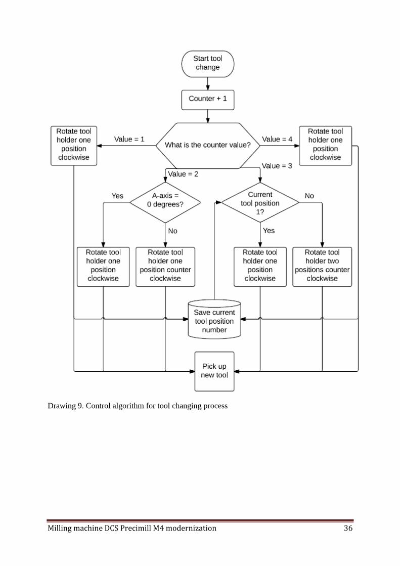
6.3.4. The logic of choosing the right tool
Choosing the right tool for the Glass-ceramics or Titan/Cobalt-Chrome is processed the same
way and is similar in any way. Therefore only metal tools changing is being explained in this
paragraph, but it has to be reminded that the same process applies to Glass-ceramics as well.
The first tool has to be manually selected and it is always the 3 mm tool. The tools will be
placed to the rollercoaster in the following order:
1) Position number 1 – 3 mm tool
2) Position number 2 – 2 mm tool
3) Position number 3 – 1 mm tool
When the first tool change appears the machine has to put away the 3 mm tool and change it to
2 mm tool. In order to do that the machine first puts away position 1 tool. Then the rollercoaster
moves clockwise until the tool changing position is reached and the machine picks up position
number 2 tool. As some of the milled products need more smooth surface treatment than the
others this is the place where the controller has to know what is the angle for the A-axis. The
CAM software calculates the G-code in a way that first one side of the block is milled and then
the other side of the block is milled, so when the second tool change appears the machine puts
away tool and then depending on whether the A-axis is on zero or hundred and eighty degree
angle the next tool is chosen. When the A-axis angle is zero degrees the rollercoaster will move
clockwise and the machine will pick up tool in position 3. When the A-axis is hundred and
eighty degrees the machine will move counter clockwise and pick up tool in position 1.
The next tool change depends on what kind of tool was used in previous phase. When tool in
position 3 was used then the machine will have to move counter clockwise two spots and pick
up tool in position 1. When the tool from position 1 was in the spindle the tool holder has to
move clockwise for one spot and pick up tool in position 2.
After the use of tool in position 2 again there will be no more tool changes as the machine uses
the slimmest tool only on one side. If the tool from position 1 was in the spindle the machine
has to change for the tool in the position number 2.
Control algorithm for this process is brought out in Drawing 9.
Milling machine DCS Precimill M4 modernization 36
Drawing 9. Control algorithm for tool changing process

Milling machine DCS Precimill M4 modernization 37
6.4. Electrical changes and solutions
The new system for the machine needs some changes in electrical area as some of the old
systems used are now left aside and some of the new solutions need different kind of electrical
connections. The basic solution of the new electrical scheme is brought in drawing 10. The
main power supply comes from usual wall socket and delivers 230 VAC to the system. From
there the power is divided mostly into four groups.
The first group uses directly 230 VAC for their work. Main devices that use this power supply
are spindle motor, cooling fans and emulsion pump. Their work is controlled by relays,
contactors and switches though.
The second group uses 1,5 kVA transformer that supplies 40 VDC and 24 VDC voltages. 40
VDC power supply is used only by linear movement axis motors, but before it reaches the
motors the voltage is being raised up to 56 VDC by existing electrical scheme (Scheme shown
in Extra 12). From the 24 VDC transformer output the power supply is gotten for tool holder
motor, existing safety systems and door buttons, A-axis motor power supply.
The third group from the main supply is 230VAC to 12 VDC power transformer that the author
added. It is used to supply digital power for axis amplifiers.
The fourth and final group is 230 VAC to 5 VDC power transformer that is used to power
encoders.

Milling machine DCS Precimill M4 modernization 38
Drawing 10. Simplified main electrical scheme
6.4.1. Devices controlled by relays and contactors
The main devices that are controlled by different types of switches are spindle control motor,
emulsion pump and tool holder rotation motor. The spindle control motor is controlled by an
existing contactor that has 12 VDC coil for switching the contactor. This 12 VDC control signal
is gotten from Arduino UNO controller. The same solution is used for the emulsion pump. Tool
holder rotation motor is controlled by two relays that are controlled by Arduino UNO board.
Two relays are used because the motor has to be able to work in both directions.

Milling machine DCS Precimill M4 modernization 39
6.5. Block holding system for glass-ceramics
When the need for glass-ceramics block holder game up, it was considered again to rebuild
the machine to use round block holder. The round block holder already has a block for the
glass-ceramics and either way we would have to order one of the holders: round block holder
or squared block holder for the glass-ceramics. After considering both opportunities again it
was decided that squared block holders will be used and new holder for the glass-ceramics
will be ordered. This decision was made because the mechanical work for rebuilding the
machine would be time consuming and might turn out to be quite expensive and the company
still has a lot of unused squared material blocks that need to be used. Drawing for the new
holder was made in order to produce the part.
Drawing 11. Block holder drawing

Milling machine DCS Precimill M4 modernization 40
While modelling the new block holder it was important to make sure that the blocks would be
in the same point from the zero-point than they are in the new machine. This is important
because the CAM does the calculations according to the iMes 750i machine and this gives the
author a chance to use the same G-code transformer for full blocks and glass-ceramic blocks
as well. Therefore measurements form the round block holder centre were taken and the same
measurements were transferred to the squared block holder.
For the small blocks to be in the right position some of the measures of the block have to be
quite precise. The 13 mm wall is the first thing that has to be very precise. Only 0.05 mm
error will be tolerated. The other things that have to be very precise are M3 screw holes as
these holes are used to attach small glass-ceramic blocks to the block holder. Only 0.05 mm
error will be tolerated there as well. Last precise holes have to be the 6 mm diameter holes
where the small blocks holders are attached. For these holes tolerance of 0.05 mm also
applies.
Other measurements do not have to be that precise because they are not really used for
positioning the small blocks to the correct places. For other measurements tolerance of 0.2
mm is used.
6.6. G-code and changing it
G-code is the main code used in CNC control programs. When it is opened with Notepad
program it seen that the G-code is basically a text file where is mostly written different axis
positions. It also has information about the specific job, like its name, materials decreasing
factor, expected milling time etc. The main rows for process look like following:
G1 X-7.03859 Y8.15368
G1 X-7.07858 Y8.14841 Z4.87724
G1 X-7.19856 Y8.13408 Z4.90931
G1 X-7.27854 Y8.12351 Z4.92787
G1 X-7.39852 Y8.10678 Z4.95226
On these random but usual rows from the code can be read out the following information. G1
or G0 indicates whether the spindle is working or not. G1 implies that the spindle is working.

Milling machine DCS Precimill M4 modernization 41
Next the X value from the first row of the example (-7.03859) indicates the position where X-
axis should go and the same explanation applies to Y-, Z- and A-axis too.
In order to make the same G-code work on DCS Precimill M4 and iMes 750i some changes in
the code have to be made. The author has worked with VBA and Excel before and that is why
it was decided to modify the code in Excel using Macros. The code can be easily imported to
Excel and later on it can be exported as a text file.
First changes that have to be made is recalculating the axis values. The X-, Y-, Z- and A-axis
will need coefficient to adapt them with the CAM calculations. As the machine does not work
yet those exact coefficients are unknown. The G0 and G1 do not need any changing as the work
of the spindle is the same for both machines. Another thing that needs to be re-written totally is
tool changing process. The iMes machine uses specially made CNC controlling software and it
has integrated tool changing part in it. When the tool needs to be changed a new window is
opened that does the tool changing and measuring of the tool. Mach3 does not have an add-in
that could to the same job, therefore the tool changing part has to be partially made in G-code
and another part has to be done by different controller. According to the plan the tool changing
process should be re-written in a way that the machine would first put away the tool and then
notify Arduino controller to start its part of the job. Later on the machine should wait for the
signal from Arduino and finish the tool changing process. After the tool change process is
complete the machine has to return to its milling job and move according to original G-code
again.
Milling machine DCS Precimill M4 modernization 42
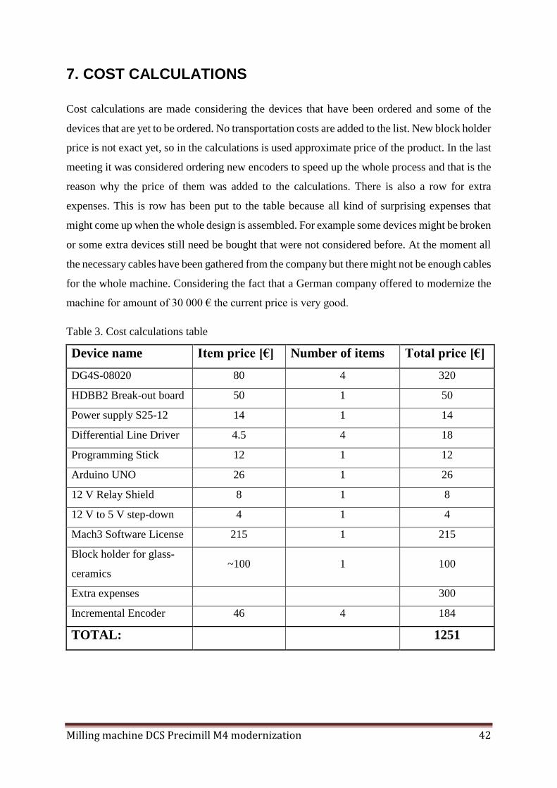
7. COST CALCULATIONS
Cost calculations are made considering the devices that have been ordered and some of the
devices that are yet to be ordered. No transportation costs are added to the list. New block holder
price is not exact yet, so in the calculations is used approximate price of the product. In the last
meeting it was considered ordering new encoders to speed up the whole process and that is the
reason why the price of them was added to the calculations. There is also a row for extra
expenses. This is row has been put to the table because all kind of surprising expenses that
might come up when the whole design is assembled. For example some devices might be broken
or some extra devices still need be bought that were not considered before. At the moment all
the necessary cables have been gathered from the company but there might not be enough cables
for the whole machine. Considering the fact that a German company offered to modernize the
machine for amount of 30 000 € the current price is very good.
Table 3. Cost calculations table
Device name Item price [€] Number of items Total price [€]
DG4S-08020 80 4 320
HDBB2 Break-out board 50 1 50
Power supply S25-12 14 1 14
Differential Line Driver 4.5 4 18
Programming Stick 12 1 12
Arduino UNO 26 1 26
12 V Relay Shield 8 1 8
12 V to 5 V step-down 4 1 4
Mach3 Software License 215 1 215
Block holder for glass-
ceramics ~100 1 100
Extra expenses 300
Incremental Encoder 46 4 184
TOTAL: 1251

Milling machine DCS Precimill M4 modernization 43
8. SUMMARY
The project was started with a plan that seemed easily feasible with couple of months but during
the execution process the project got more and more complicated. The first parts of the work
that mostly included maintenance went well with only few set-backs on the way like finally
getting the greasing nozzle’s transformation for the maintenance process. The delay of course
made the assembly a bit harder as the dismounting was done a month ago and the author could
not remember the positions of some of the parts. Fortunately pictures were taken for precaution
and all the information was eventually gathered.
The decision about the change of the block holder was done during the meeting with the second
advisor. It was decided that the block holder should not be changed as it would need mechanical
reconstruction of the machine and there is a lot of unused squared material in the storage.
The processes of finding new devices was the smoothest one as enough information was
available online. All the devices that were ordered had very specific manuals available and that
made the research a lot easier. The project was still delayed a couple of times as some of the
parts that were ordered arrived two months after the order was made. Equipment for the
machine was at first ordered device by device because of lack of information about the milling
machine. Installing of the devices turned out to be a lot harder though as during the process it
became clear that the original plan cannot be carried out. The machine was built a much more
integrated than estimated. The main problem was caused by the controlling computer that did
not work anymore. In that computer different controlling schemes were added with ribbon cable
and no information about those connections were known. Fortunately the gears did not need
any drastic changes as they were in good shape. Only the belts need to be strained.
The choice of the new CNC control software was quite easy to make as well. Two programs
were recommended on the website where the devices were purchased. Further investigation
broadened the choice to three different software options. Two of the choices were the same
program’s different versions and as one of them is really new the author made up his mind of
choosing Mach3 software as it seemed to be the most reasonable solution.
During the process it was decided to design a new controlling system from the scratch as the
old system was too integrated for restauration. The designing process started with generating
the main algorithm for the whole process. This scheme was produced quite fast as any of the
specific solutions did not fit to the scheme. Then the author described the connections for the

Milling machine DCS Precimill M4 modernization 44
main devices separately. The connections for the motor controllers and break-out board were
explained the most thoroughly as they were the most complicated ones. More brief overviews
were given to simpler devices connections as UC-100 motion controller and differential line
module. After that the author started solving seemingly the most complicated problem, the tool
changing process. It is complicated because the process has to be controlled by another
controller that still needs to communicate to the software that is used. The process was started
by finding out the basic solution for the process. This is where it was made clear that the
controller can communicate with the main program via break-out board that has some extra
outputs. Then the devices for conducting the process were chosen. Arduino UNO
programmable board was chosen to control the process as the author has experience working
with that board. For connecting the board a relay module was purchased. After the devices had
been chosen the connections to the other parts were worked out and explained. Moving forward
the solution of choosing the right tool was explained by algorithm. Then the author worked out
some basic electrical solutions to the machine and explained them. After the electrical part the
block holding problem needed to be solved again as the small glass-ceramic blocks need a
special solution. Then the change for the round block holder came up again but in the end it
was still decided to make a new small blocks holder for the squared block holder. Drawing of
the design with important measurements were then brought out. Finally the necessary changes
in the G-code are explained and the solution on how to change the code is explained.
The last part of the work is calculating the cost of the whole project. Purchased devices with
their prices are listed to calculate the cost of the whole project. There are also some devices that
still need to be ordered. The author left some room for unforeseen expenses as some surprises
still might come up.
Considering the whole process it was very instructive to the author. Comparing this project to
usual more theoretical projects a lot of unexpected time delays occurred that the author can
consider in future projects. Also it was a good lesson because the project got a lot harder during
the execution. The projects carried out until this one were quite specific and feasible.
The author will consider the project as a success. In the near future the author will try to put his
design into operation step-by-step. At first the axis movements have to be correct. For that the
axis amplifiers have to be in working order and new encoders have to arrive. Then the G-code
has to be modified. When the axis movements are in working order, only then the tool changing
process and new block holders for glass ceramics will be considered.

Milling machine DCS Precimill M4 modernization 45
8. KOKKUVÕTE
Projekti alustati plaaniga, et see on paari kuuga kergesti teostatav kuid protsessi käigus muutus
projekti aina raskemaks. Esimesed osad tööst mis käsitlesid peamiselt seadme hooldust läksid
ladusalt, vaid mõne üksi tagasilöögiga nagu näiteks õlitusnipli vahelüli saamine. Viivitus
muutis muidugi seadme kokkupaneku raskemaks, kuna see oli lahti võetud juba kuu aega tagasi.
Õnneks oli autor ettevaatusabinõuna teinud seadmest pilte ning seadme detailide paigutused
olid fotodel piisavalt hästi näha.
Otsus blokihoidja vahetuse kohta võeti vastu koosolekul koos ettevõtte tehnika juhiga. Lõpuks
otsustati, et blokihoidjat ei vahetata ümmarguse vastu kuna see nõuaks mehaanilist
rekonstrueerimist ning ettevõttel on laos hulgaliselt kandilisi blokke alles.
Uute seadmete valimise protsess möödus kõige sujuvamalt, kuna veebis oli piisavalt
informatsiooni saadaval. Kõikidel seadmetele, mis telliti olid olemas väga spetsiifilised
kasutusjuhendid ning see muutis uurimise oluliselt lihtsamaks. Projektis tekkisid siiski mitmed
viivitused tänu ettevõtete vahelistele tarneaegadele, näiteks tuli oodata mõnda detaili peaaegu
kaks kuud. Algselt telliti seadmeid detaili haaval, kuna freesmasina kohta ei olnud palju
informatsiooni ning autor ei olnud kindel kui suures osas seadmed tuleb välja vahetada.
Seadmete paigaldamisel tekkis probleem, mille käigus saadi teada, et esialgne
moderniseerimise plaan ei ole reaalselt teostatav. Probleem põhines asjaolul, et freesmasin oli
ehitatud väga integreeritult ning eraldi seadmete vahetamine on raskendatud. Peamiseks
probleemi allikaks oli masina juhtarvuti, mis enam ei töötanud. Juhtarvutile oli pandud lisaks
kontrollerid, mis olid ühendatud lintkaabliga ning nende seadmete kohta puudus igasugune
informatsioon. See avastuse põhjal võeti vastu otsus kogu juhtimissüsteem algusest peale üles
ehitada, kuna see tundus lihtsam kui vana süsteemi restaureerimine. Õnneks ülekanded ei
vajanud erilisi muudatusi, kuna peale inspektsiooni otsustati, et need on heas seisukorras. Ainult
rihmad vajasid pingutamist.
Uue CNC tarkvara valimine tuli ka suhteliselt kergelt kuna kahte programmi oli soovitatud
samal veebilehel kust telliti mootori kontrollerid. Lähemal uurimisel lisandus valikusse ka
kolmas programm, mis iseenesest oli ühe eelneva valiku uuem versioon. Autor langetas otsuse
kasutada Mach3 tarkvara, mis tundus vägagi mõistlik.
Protsessi käigus otsustati juhtimissüsteem alates nullist uuesti üles ehitada, kuna see tundus
lihtsam kui vana süsteemi restaureerimine. Uue süsteemi projekteerimine algas peamise

Milling machine DCS Precimill M4 modernization 46
juhtalgoritmi genereerimisega. Skeem suudeti välja töötada küllaltki ladusalt, kuna
spetsiifilised osad sellele ei mahtunud. Seejärel kirjeldas autori peamiste seadmete ühendusi
eraldi. Käsitleti teljevõimendite ja „break-out board“ ühendusi. Seejärel anti põgusam
ülevaade lihtsamatest ühendustest nagu UC-100 liikumise kontrolleri ja diferentseeriva
mooduli ühendused. Seejärel asus autor lahendama kõige keerulisemat probleemi, terade
vahetamise protsessi. Kõige keerulisemaks on ta tituleeritud, kuna selle protsessi jaoks on vaja
kasutada eraldiseisvat kontrollerit, mis peab siiski olema võimeline suhtlema põhisüsteemiga.
Autor tegi suutis leida lahenduse, kus suhtlus toimub läbi „break-out board“ lisaühenduste.
Seejärel valiti protsessi juhtimiseks peamine kontroller, Arduino UNO, kuna autor on selle
seadmega varasemalt kokku puutunud. Ühenduste tegemiseks soetati Arduino plaadile
lisaseadmena relee moodul. Peale seadmete valimist näidati ära seadmete ühendused ülejäänud
masinaga. Seejärel seletati algoritmi abiga tera vahetamise peamine protsess. Järgnevalt
projekteeris autor seadmele peamise elektriskeemi ning selgitas oma valikut. Peale elektriosa
tuli jällegi kõne alla blokihoidja vahetus, kuna klaas-keraamika jaoks on vaja spetsiaalset
väikeste blokkide hoidjat. Töö tulemusena projekteeriti aga väikeste blokkide hoidja kandilisele
blokihoidjale. Projekteeritud detaili joonis koos tähtsamate mõõtmetega on töös välja toodud.
Lõpuks on seletud ka G-koodi muutmise aluseid ning põhjuseid.
Viimane osa sisaldab endas kuluanalüüsi kus on tabelis välja toodud kõik tehtud kulutused.
Lisaks on kirja pandud kulutused, mis on vaja veel projekti käigus teha ning ka varusumma,
kuna võib esineda ka veel ettearvamatuid kulusid.
Kogu protsessi arvesse võttes osutus see autorile väga õpetlikuks. Võrreldes seda projekti
eelnevalt teostatutega, mis on olnud oluliselt teoreetilisemad, tekitasid projekti läbiviimisel
olulisi probleemi ajalised viivitused. Edasiste projektide planeerimisel tuleb selliste ajaviidete
arvestamine kindlasti kasuks. Lisaks oli autorile õpetlik ka projekti raskemaks muutumine.
Senised projektid on olnud küllaltki spetsiifilised ning sarnaselt plaanile teostatavad.
Autor loeb töö edukaks, kuna projekt muutus oluliselt keerulisemaks ning vajalik teoreetiline
töö on nüüdseks tehtud. Järgnevalt proovib autor enda projekteeritud süsteemi töösse rakendada
järk-järgult. Esmalt tuleb telgede liikumine saada täpseks ja kontrollituks. Selleks tuleb lõpuni
viia teljevõimendite seadistamine ning G-koodi muutmine. Järgnevalt tuleb oodata uute
teljevõimendite saabumist. Kui telgede liikumine on kontrolli alla saadud, alles siis võetakse
käsile terade vahetamise protsess ning klaas-keraamika jaoks mõeldud blokihoidja
valmistamine.

Milling machine DCS Precimill M4 modernization 47
9. REFERENCES
[1] CNCDrive, “cncdrive.com,” [Online]. Available: http://cncdrive.com/UC100.html.
[2] GeckoDrive, “www.geckodrive.com,” [Online]. Available:
http://www.geckodrive.com/g320x.html.
[3] CNCDrive, “cncdrive.com,” [Online]. Available: http://cncdrive.com/UC100.html.
[4] CNCDrive, “cncdrive.com,” [Online]. Available: http://cncdrive.com/HDBB2.html.
[5] CNCDrive, “cncdrive.com,” [Online]. Available:
http://cncdrive.com/Difflinedriver.html.
[6] CNCDrive, “cncdrive.com,” [Online]. Available:
http://www.shop.cncdrive.com/index.php?productID=268.
[7] CNCDrive, “cncdrive.com,” [Online]. Available: http://cncdrive.com/Progstick.html.
[8] CNCDrive, “cncdrive.com,” [Online]. Available: http://cncdrive.com/UCCNC.html.
[9] Artsoft, “www.machsupport.com,” [Online]. Available:
http://www.machsupport.com/software/mach3/.
[10] Arduino, “www.arduino.cc,” [Online]. Available:
http://www.arduino.cc/en/Main/ArduinoBoardUno.
[11] Sainsmart, “www.sainsmart.com,” [Online]. Available: http://www.sainsmart.com/16-
channel-12v-relay-module-for-pic-arm-avr-dsp-arduino-msp430-ttl-logic.html.

Milling machine DCS Precimill M4 modernization 48
EXTRAS
E1 Milling machine DCS Precimill M4
Extra 1. Pictures of the milling machine DCS Precimill M4

Milling machine DCS Precimill M4 modernization 49
E2 Milling machine Wieland iMes-750i
Extra 2. Picture of milling machine Wieland iMes-750i
Milling machine DCS Precimill M4 modernization 50
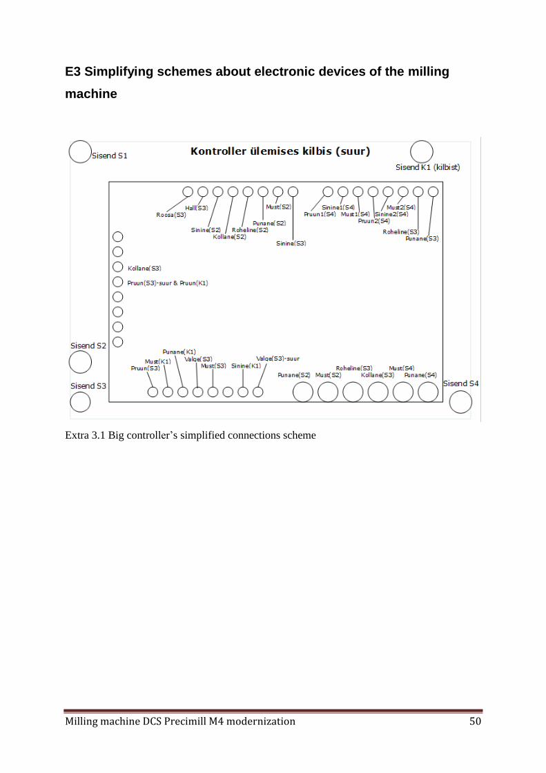
E3 Simplifying schemes about electronic devices of the milling
machine
Extra 3.1 Big controller’s simplified connections scheme

Milling machine DCS Precimill M4 modernization 51
Extra 3.2 Smaller controller’s simplified connections scheme

Milling machine DCS Precimill M4 modernization 52
Extra 3.3 End-switches simplified connections schemes

Milling machine DCS Precimill M4 modernization 53
E4 Greasing nozzle’s thread transition drawing
Extra 4. Greasing nozzle’s thread transition drawing

Milling machine DCS Precimill M4 modernization 54
E5 DG4S-08020 picture
Extra 5. Picture of DG4S-08020 axis amplifier

Milling machine DCS Precimill M4 modernization 55
E6 HDBB2 Break-out Board
Extra 6. Picture of HDBB2 Break-out board

Milling machine DCS Precimill M4 modernization 56
E7 HDBB2 Centronics 36 cable connections
Extra 7. Blow diagram for Centronics 36 and LPT pin mapping

Milling machine DCS Precimill M4 modernization 57
E8 HDBB2 Break-out board screw terminal connections
Extra 8. HDDB-2 Break-out board screw terminal connections

Milling machine DCS Precimill M4 modernization 58
E9 UC-100 Motion Controller
Extra 9. Picture of UC-100 Motion Controller.

Milling machine DCS Precimill M4 modernization 59
E10 Differential Line Driver
Extra 10. Picture of Differential Line Driver

Milling machine DCS Precimill M4 modernization 60
E11 Arduino UNO
Extra 11. Picture of Arduino UNO

Milling machine DCS Precimill M4 modernization 61
E12 Relay Module
Extra 12. Picture of 8-Channel 12 V Relay Shield Module for Arduino UNO

Milling machine DCS Precimill M4 modernization 62
E13 Arduino UNO and Relay Shield’s connections
Extra 13. Drawing how to connect Arduino UNO with Relay Shield

Milling machine DCS Precimill M4 modernization 63
E14 Existing voltage raising scheme
Extra 14. Drawing of existing voltage raising scheme