Embed Size (px)
Citation preview
MIL
LEN
NIU
M S
TEEL
201
5
20
Modern mini and compact blast furnaces – operations-based design considerationsOnly a few decades ago blast furnaces of 600m3 working volume producing 0.3Mt/yr with a campaign life of up to four years were state of the art. Today, such furnaces are termed mini or compact BFs, but can attain 0.7Mt/yr and an endless campaign life by adopting the technologies of design, burdening and operation that have become the norm for today’s modern large furnaces.
Whereas only a few decades ago, typical blast furnace working volumes were below 1,000m3, today, with
furnaces now reaching 6,000m3, they are now are designated as ‘mini blast furnaces’. (POSCO Gwangyang No.1 with 6,095m3 inner volume is currently the world’s largest.)
For many scenarios, however, the furnace sizes of yesteryear remain an attractive option. Whereas decades ago, the typical 600m3³BF would have produced a maximum of 0.3Mt/yr with a campaign life of up to four years, the current state of technology and operational know-how allows such a furnace to produce more than 0.7Mt/yr while achieving the ‘endless’ campaigns familiar to steel producers with full-sized plants.
This level of productivity, and especially the reliability and supply security associated with mature technology, allows excellent integration into minimills or for taking a fi rst step towards a full scale BF-BOF integrated steelworks.
Scenarios like these are embraced by the global industry. Steel producers considering such scenarios are confronted with fundamental decisions, one of which is for the technological basis for the mini/compact BF to be included in the plant. In many cases, the furnace will be a refractory lined shell with external spray cooling. However, this option is only suitable for working volumes below 400m3. Between 400 and 1,000m3, many of the same considerations that apply to larger size BFs will hold.
OPERATIONAL BASISRegardless of global or local economic circumstances, targets for ironmaking operations have been similar throughout history and in all locations. Any operator is always asked to contribute to achieving the lowest cost operations for the site while also maximising profi t. In BF ironmaking, this translates into the following:` The lowest possible coke rate at elevated auxiliary fuel
injection
Authors: Edo Engel and Roman VaynshteynDanieli Corus
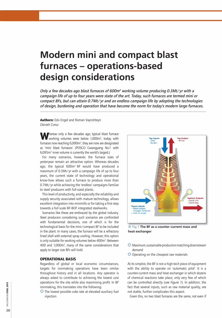
r Fig 1 The BF as a counter–current mass and heat exchanger
` Maximum, sustainable production matching downstream demand
` Operating on the cheapest raw materials
At its simplist, the BF is not a high-tech piece of equipment with the ability to operate on ‘automatic pilot’. It is a counter-current mass and heat exchanger in which dozens of chemical reactions take place, only very few of which can be controlled directly (see Figure 1). In addition, the fact that several inputs, such as raw material quality, are not stable, further complicates this aspect.
Given this, no two blast furnaces are the same, not even if
RAW MATERIALS AND IRONMAKING
a
MIL
LEN
NIU
M S
TEEL
201
5
21
Whenever stable and controlled operations are achieved, a new performance target or operating point may be defi ned, along with a well-defi ned plan to achieve the step change towards that target. If (and only if) the step change is successful and operations prove stable, further optimisation of the operating point may be achieved with minor adjustments and a next step may be defi ned.
BASIC PROCESS CONTROL EQUIPMENT AND TOOLSThe described, stepwise optimisation process can only be effected if the operator has suffi cient tools for process monitoring and control. Full size, modern BFs may be equipped with substantial instrumentation and the traditional mini BF with only a strict minimum. From the operator’s perspective, there is a basic set of instrumentation required for monitoring how the process responds to operational changes and enabling process optimisation:` Heat fl ux measurement for monitoring, for instance,
cooling losses ` Above burden probes for monitoring, for instance, gas
utilisation` Top cameras for monitoring such things as burden
charging` A Level 2 system for interpretation of measurements
and operator advice.
The basic set of control equipment may be limited to good and reliable cast house equipment for full control of taphole operation and liquid removal, as well as the right top charging system. As an alternative to the traditional double bell top, many designs have been developed. Since most of these are perfectly capable of depositing raw materials on the stockline in the location desired by the operator, reliability should be the main objective when selecting the right device for the right situation.
they are of the same design and operated at the same site. It is up to the operator develop a fundamental understanding of the processes taking place inside the furnace and to initiate and manage optimisation processes that help ironmaking operations meet the above-mentioned targets. Although some general rules may be applicable to BF operations worldwide, achieving performance beyond industry standards is a process that may take years and requires persistence as well as commitment from everyone involved.
Clearly, aiming for maximum process output while feeding the BF lower quality raw materials and reducing energy input is essentially driving the process towards it limits. With the coke layers providing the furnace with the required permeability, furnace pressure drop will require close monitoring as coke rate is reduced, and the process will experience increasing risk of irregular burden descent and other undesirable upsets. Gas fl ow will need to be kept under control as much as possible, since gas jets along the furnace wall will cause unwanted heat losses, consuming heat that would otherwise be available for heating the burden.
To accommodate the requirements imposed by the operational targets as well as maximum process stability within the (tightened) operational envelope, the operator develops set points for the process. These set points focus largely on the inputs and outputs that have most infl uence on process performance and stability. The following need to be developed:` Burden distribution strategies` Fundamental understanding of tuyere inputs (fuel,
oxygen, moisture) including operational rules of thumb
` Casting practices
In addition, raw material quality allows for substantial optimisation of the process, but obtaining the best raw materials within tightening budgets may be impossible, especially for smaller scale players.
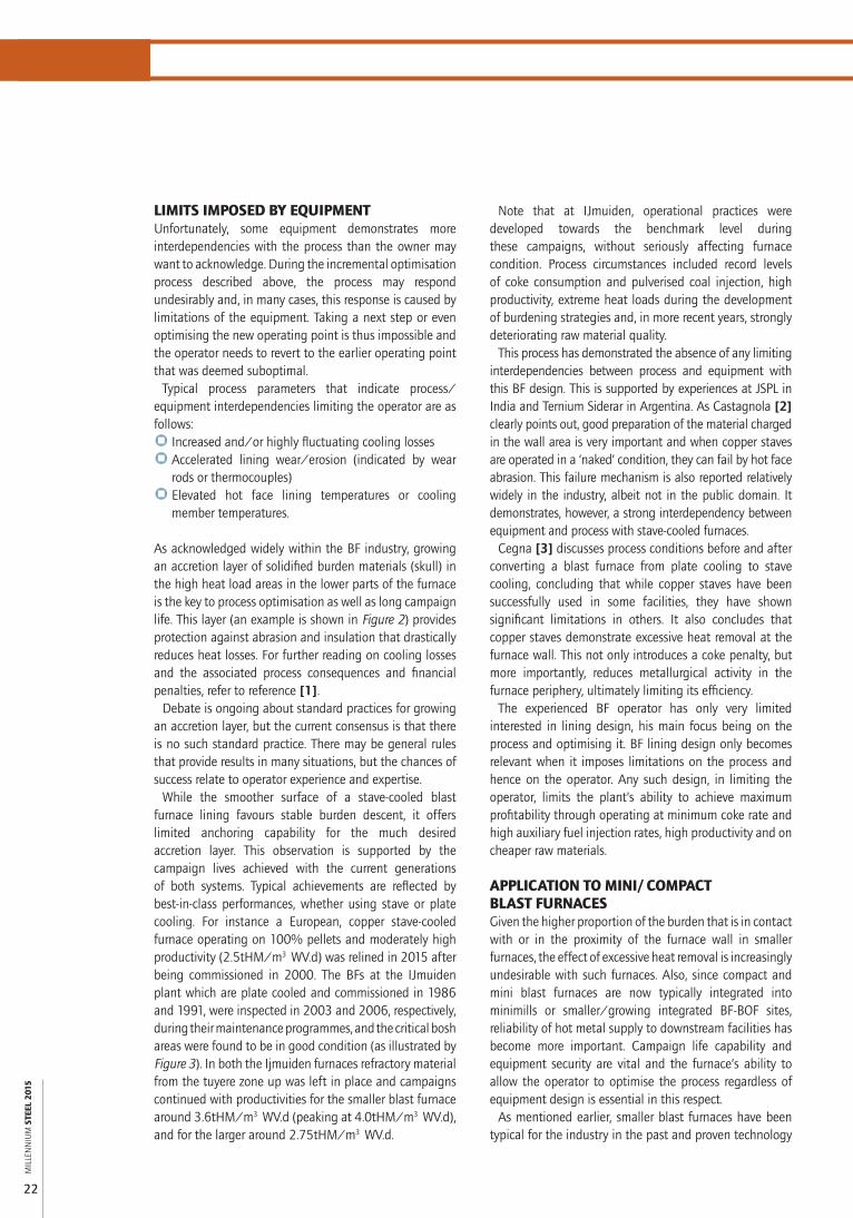
r Fig 3 IJmuiden No. 7 bosh condition after 15 years’ operation
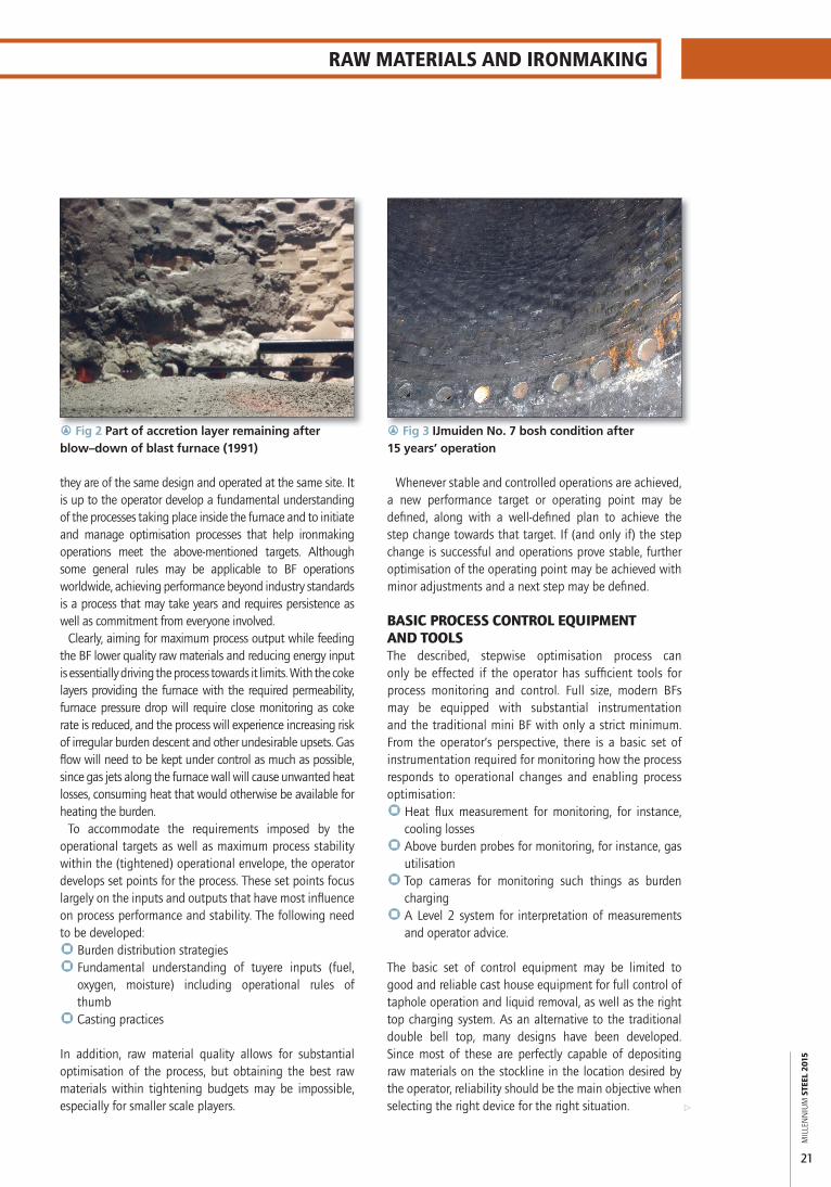
r Fig 2 Part of accretion layer remaining after blow–down of blast furnace (1991)
MIL
LEN
NIU
M S
TEEL
201
5
22
LIMITS IMPOSED BY EQUIPMENTUnfortunately, some equipment demonstrates more interdependencies with the process than the owner may want to acknowledge. During the incremental optimisation process described above, the process may respond undesirably and, in many cases, this response is caused by limitations of the equipment. Taking a next step or even optimising the new operating point is thus impossible and the operator needs to revert to the earlier operating point that was deemed suboptimal.
Typical process parameters that indicate process/equipment interdependencies limiting the operator are as follows:` Increased and/or highly fluctuating cooling losses` Accelerated lining wear/erosion (indicated by wear
rods or thermocouples)` Elevated hot face lining temperatures or cooling
member temperatures.
As acknowledged widely within the BF industry, growing an accretion layer of solidified burden materials (skull) in the high heat load areas in the lower parts of the furnace is the key to process optimisation as well as long campaign life. This layer (an example is shown in Figure 2) provides protection against abrasion and insulation that drastically reduces heat losses. For further reading on cooling losses and the associated process consequences and financial penalties, refer to reference [1].
Debate is ongoing about standard practices for growing an accretion layer, but the current consensus is that there is no such standard practice. There may be general rules that provide results in many situations, but the chances of success relate to operator experience and expertise.
While the smoother surface of a stave-cooled blast furnace lining favours stable burden descent, it offers limited anchoring capability for the much desired accretion layer. This observation is supported by the campaign lives achieved with the current generations of both systems. Typical achievements are reflected by best-in-class performances, whether using stave or plate cooling. For instance a European, copper stave-cooled furnace operating on 100% pellets and moderately high productivity (2.5tHM/m3³WV.d) was relined in 2015 after being commissioned in 2000. The BFs at the IJmuiden plant which are plate cooled and commissioned in 1986 and 1991, were inspected in 2003 and 2006, respectively, during their maintenance programmes, and the critical bosh areas were found to be in good condition (as illustrated by Figure 3). In both the Ijmuiden furnaces refractory material from the tuyere zone up was left in place and campaigns continued with productivities for the smaller blast furnace around 3.6tHM/m3³WV.d (peaking at 4.0tHM/m3³WV.d), and for the larger around 2.75tHM/m3³WV.d.
Note that at IJmuiden, operational practices were developed towards the benchmark level during these campaigns, without seriously affecting furnace condition. Process circumstances included record levels of coke consumption and pulverised coal injection, high productivity, extreme heat loads during the development of burdening strategies and, in more recent years, strongly deteriorating raw material quality.
This process has demonstrated the absence of any limiting interdependencies between process and equipment with this BF design. This is supported by experiences at JSPL in India and Ternium Siderar in Argentina. As Castagnola [2] clearly points out, good preparation of the material charged in the wall area is very important and when copper staves are operated in a ‘naked’ condition, they can fail by hot face abrasion. This failure mechanism is also reported relatively widely in the industry, albeit not in the public domain. It demonstrates, however, a strong interdependency between equipment and process with stave-cooled furnaces.
Cegna [3] discusses process conditions before and after converting a blast furnace from plate cooling to stave cooling, concluding that while copper staves have been successfully used in some facilities, they have shown significant limitations in others. It also concludes that copper staves demonstrate excessive heat removal at the furnace wall. This not only introduces a coke penalty, but more importantly, reduces metallurgical activity in the furnace periphery, ultimately limiting its efficiency.
The experienced BF operator has only very limited interested in lining design, his main focus being on the process and optimising it. BF lining design only becomes relevant when it imposes limitations on the process and hence on the operator. Any such design, in limiting the operator, limits the plant’s ability to achieve maximum profitability through operating at minimum coke rate and high auxiliary fuel injection rates, high productivity and on cheaper raw materials.
APPLICATION TO MINI/COMPACT BLAST FURNACESGiven the higher proportion of the burden that is in contact with or in the proximity of the furnace wall in smaller furnaces, the effect of excessive heat removal is increasingly undesirable with such furnaces. Also, since compact and mini blast furnaces are now typically integrated into minimills or smaller/growing integrated BF-BOF sites, reliability of hot metal supply to downstream facilities has become more important. Campaign life capability and equipment security are vital and the furnace’s ability to allow the operator to optimise the process regardless of equipment design is essential in this respect.
As mentioned earlier, smaller blast furnaces have been typical for the industry in the past and proven technology

RAW MATERIALS AND IRONMAKING
MIL
LEN
NIU
M S
TEEL
201
5
23
a
has been applied in many situations that support the case for equipping today’s mini BFs with this mature equipment in order to meet today’s operational and fi nancial targets for smaller plants. A small number of these furnaces will be presented below.
SOUTHERN EUROPE, 621M3³WORKING VOLUME In 1985, the Danieli Corus (then ESTS) high conductivity copper plate-cooled design was applied to the critical tuyere zone and bosh/belly area of a 621m3³ working volume blast furnace in southern Europe. The furnace profi le and scope of work is indicated in Figure 4.
The furnace was put into operation in 1986, was taken out of operation in 2006 and fi nally decommissioned in 2009. Although production was interrupted over that 23 year period, no intermediate reline activities had been required and the lining proved to be in good condition as shown in Figure 5.
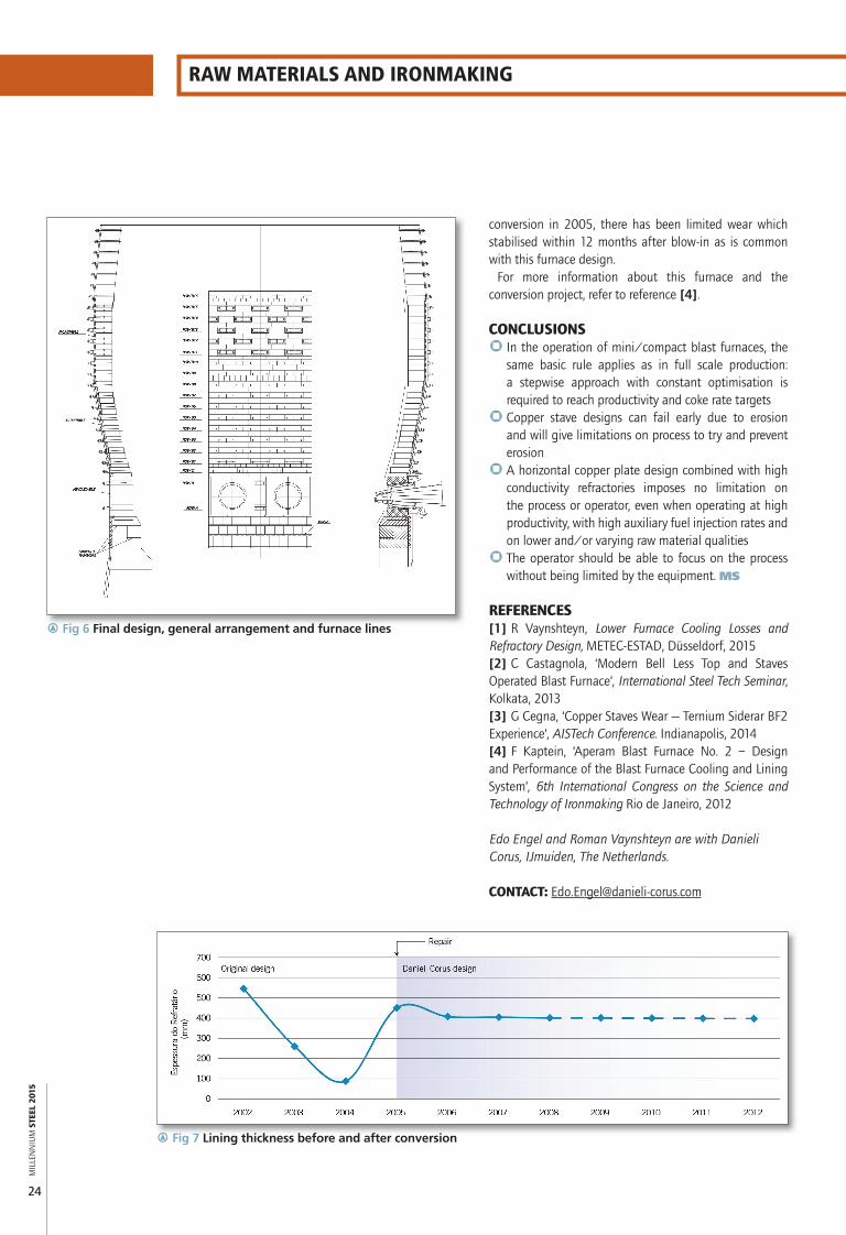
LATIN AMERICA, 631M3³WORKING VOLUME After a repair in 2001/02, a 631m3³blast furnace was recommissioned by a stainless steel producer in Latin America. Problems in the bosh occurred only two months after blow-in. High heat loads and hot spots were observed in the bosh and belly area followed by a breakout six months after start-up. The furnace underwent temporary repairs to get back into production, while at the end of 2003, the engineering and procurement for a more permanent repair started. Until the permanent repair could be executed, the furnace continued operating with maximum attention on protecting the bosh, utilising a ‘special charge’ that promoted a stable accretion to form. Although effective, this limited the productivity of the furnace. The furnace was stopped for a reline by Danieli Corus in 2005. The scope included the top layer of the hearth wall, tuyere belt, bosh and belly (see Figure 6). Some repair work was also carried out in the taphole area when damage was identifi ed during the shutdown. The bosh and belly were converted to the high conductivity plate-cooled design promoted by Danieli Corus. An additional row of plate coolers was installed just above the tuyere coolers.
Ten years have passed since the furnace was blown in, whereas the client’s original requirement was for a seven-year campaign extension. The furnace lining and cooling is in very good shape, despite having been exposed to severe process conditions such as switching between metallurgical coke and charcoal as a reducing agent. The furnace will continue its normal operation and the operators confi rm the furnace’s ability to allow for process optimisation without being limited by the furnace design.
Figure 7 shows the furnace’s lining thickness throughout the current (extended) campaign. It is clearly seen that before the conversion, lining wear was rapid. After the
r Fig 5 Furnace internal condition in 2006
r Fig 4 Blast furnace general arrangement
MIL
LEN
NIU
M S
TEEL
201
5
24
RAW MATERIALS AND IRONMAKING
conversion in 2005, there has been limited wear which stabilised within 12 months after blow-in as is common with this furnace design.
For more information about this furnace and the conversion project, refer to reference [4].
CONCLUSIONS` In the operation of mini/compact blast furnaces, the
same basic rule applies as in full scale production: a stepwise approach with constant optimisation is required to reach productivity and coke rate targets
` Copper stave designs can fail early due to erosion and will give limitations on process to try and prevent erosion
` A horizontal copper plate design combined with high conductivity refractories imposes no limitation on the process or operator, even when operating at high productivity, with high auxiliary fuel injection rates and on lower and/or varying raw material qualities
` The operator should be able to focus on the process without being limited by the equipment. MS
REFERENCES[1] R Vaynshteyn, Lower Furnace Cooling Losses and Refractory Design, METEC-ESTAD, Düsseldorf, 2015[2] C Castagnola, ‘Modern Bell Less Top and Staves Operated Blast Furnace’, International Steel Tech Seminar, Kolkata, 2013[3] G Cegna, ‘Copper Staves Wear — Ternium Siderar BF2 Experience’, AISTech Conference. Indianapolis, 2014[4] F Kaptein, ‘Aperam Blast Furnace No. 2 – Design and Performance of the Blast Furnace Cooling and Lining System’, 6th International Congress on the Science and Technology of Ironmaking Rio de Janeiro, 2012
Edo Engel and Roman Vaynshteyn are with Danieli Corus, IJmuiden, The Netherlands.
CONTACT: [email protected]
r Fig 7 Lining thickness before and after conversion
r Fig 6 Final design, general arrangement and furnace lines