Embed Size (px)
Citation preview

Modern Ethernet
Chapter 6

Contents
• Define the characteristics, cabling, and connectors used in 10BaseT and 10BaseFL
• Explain how to connect multiple Ethernet segments
• Define the characteristics, cabling, and connectors used in 100Base and Gigabit Ethernet
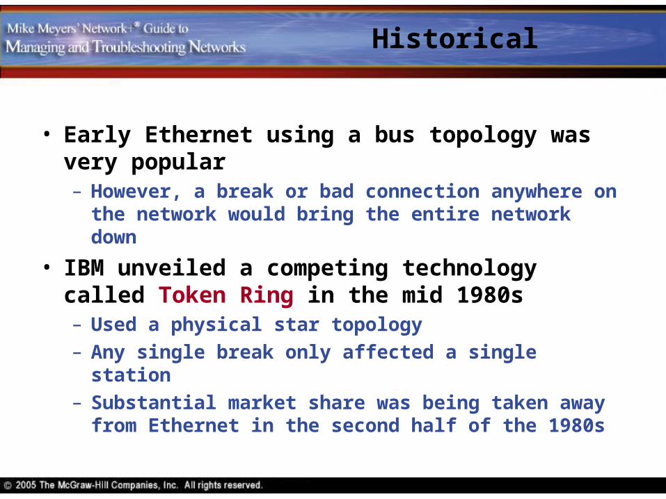
Historical
• Early Ethernet using a bus topology was very popular– However, a break or bad connection anywhere on the
network would bring the entire network down
• IBM unveiled a competing technology called Token Ring in the mid 1980s– Used a physical star topology
– Any single break only affected a single station
– Substantial market share was being taken away from Ethernet in the second half of the 1980s

Ethernet’s Response
• Ethernet manufacturers countered with an improved Ethernet– Physical star for robustness
– Adopt inexpensive UTP cabling instead of the more expensive coax
– Same frame type of earlier versions for compatibility
• The new and improved Ethernet is called 10BaseT

10BaseT

10BaseT
10BaseTSpeed
10 MbpsSignal TypeBaseband
A single signalon the cable
Type of cableTwisted Pair

10BaseT Topology
• 10BaseT uses a physical star topology with each node connected to a central hub

10BaseT Topology
• The single segment is still there – having been shrunk to the inside of the hub
• The hub is a multiport repeater operating at the Physical layer
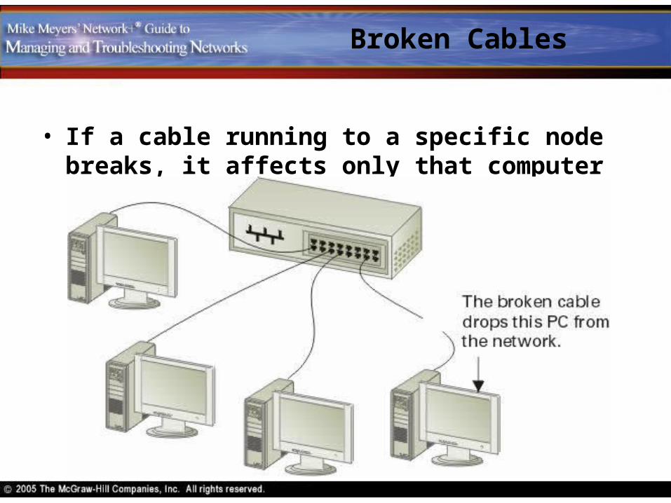
Broken Cables
• If a cable running to a specific node breaks, it affects only that computer

Broken Hub
• If the segment inside the hub breaks, then the entire segment fails

Hub Sizes
• The main difference between hubs is the number of ports

UTP
• Unshielded Twisted Pair (UTP)
• 10BaseT requires CAT 3 (or higher), two-pair, UTP cable– Installers usually install four-pair cable
• One pair sends data and one pair receives data

RJ-45 Connectors
• RJ-45 connectors are used on the ends of the cable
• Each pin in the connector connects to a different wire– 8 pins numbered 1 through 8
– Pins 1 & 2 send data; 3 & 6 receive data

Crimping
• A crimper is a tool used to secure an RJ-45 connector to the end of the cable
• Each wire must connect to the proper pin
• Color-coded wires are used
• Each pair has a solid and a striped wire

Wiring Standards
• Defined by the Telecommunications Industry Association/Electronics Industries Alliance (TIA/EIA)
• Two standards exist for four-pair UTP for 10BaseT networks– T-568A
– T-568B

Wiring Standards
EIA/TIA 568A standard
EIA/TIA 568B standard
Brown
Brown/WhiteOrange
Blue/WhiteBlue
Orange/WhiteGreen
Green/White
BrownBrown/White
Blue/WhiteBlue
Green
Green/WhiteOrange
Orange/White
1
2
3
4
5
67
8
1
2
3
4
5
6
7
8

Split Pairs
• Two pairs of wires are used in 10BaseT– 1 & 2
– 3 & 6
• Why split the second pair (3 & 6)?– This is to provide backward compatibility with
telephone wiring
– Telephone cables use RJ-11 connectors• A single line is wired using 2 & 3
• A second line is wired using 1 & 4
• An RJ-11 may be plugged into an RJ-45 outlet

Which Standard?
• Both 568A and 568B see wide spread usage
• The important thing is to be consistent within your organization

10BaseT Limitations
• Distance between hub and computer may not exceed 100 meters
• The maximum number of computers connected to a hub (or bank of hubs) is 1024

10BaseT Summary
• Speed: 10 Mbps
• Signal type: Baseband
• Distance: 100 meters between the hub and the node
• No more than 1024 nodes per hub
• Star bus topology: physical star, logical bus
• Uses CAT3 or better UTP cabling with RJ-45 connectors

10BaseFL
• 10BaseFL is a fiber-optic version of 10BaseT
• Uses pulses of light instead of electricity
• Longer distances – up to 2 kilometers
• Immune to electrical interference
• More secure – harder to tap into

10BaseFL Cable
• Uses fiber optic cable called multimode

10BaseFL Card

10BaseFL Summary
• Speed: 10 Mbps
• Signal type: Baseband
• Distance: 2000 meters between the hub and the node
• No more than 1024 nodes per hub
• Star bus topology: physical star, logical bus
• Uses multimode fiber optic cabling with ST or SC connectors

Connecting Ethernet Segments

Expanding the Network
• Additional hubs may be necessary– When all the ports are used up on a hub
– To provide fault tolerance
• Hubs may connected using coaxial cable or crossover cables
10BaseT hub with BNC connector used to connect
to another hub

Populated Segment
• A segment connecting two hubs may be populated by having one or more nodes connected to it

Crossover Cables
• Hubs may be connected using crossover cables
• In a crossover cable the send and receive pairs are reversed– One end uses 568A and the other 568B

Crossover Ports
• To avoid rewiring some hubs have special ports that switch the wires inside the hub
Uplink, crossover, in port, or out port all refer to a port where the
wires have been reversed
Connecting Hubs
• When connecting two hubs together, use a crossover cable between two regular ports
• Or use a straight-through (normal) cable between a regular port on one hub and a crossover port on the other hub– Some hubs have a button that switches a port between
normal and crossover
Two PCs may be connected by using a crossover cable from one NIC to the other NIC.
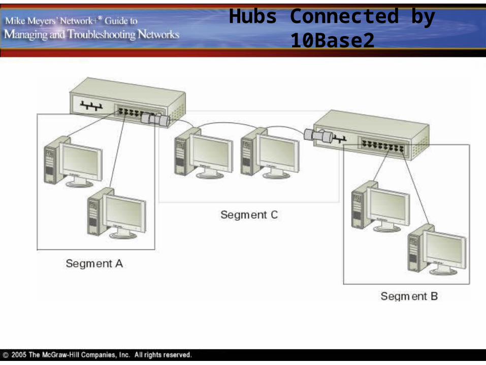
Hubs Connected by 10Base2

Broken Cables
• Segment C’s failure prevents communication between segments A and B, but does not affect communication within segments A and B

5-4-3 Rule
• Multiple Ethernet segments connected together with hubs and repeaters form one large collision domain
• The 5-4-3 rule limits the size of a collision domain

5-4-3 Rule
• In a collision domain no two nodes may be separated by more than– 5 segments
– 4 repeaters
– 3 populated segments• Populated segments have nodes
attached
• Unpopulated segments, or link segments, connect other segments

5-4-3 Rule
• Here’s a network with 6 segments that complies with the 5-4-3 rule

High-Speed Ethernet

100Base Ethernet
• Fast Ethernet refers to any of several Ethernet flavors that operate at 100 Mbps

100BaseT
• IEEE supports two variations: 100BaseTX and 100BaseT4– 100 means a speed of 100 Mbps
– Star bus topology
– UTP cabling and hubs
• 100BaseTX uses CAT 5e or better cabling and two pairs of wires
• 100BaseT4 uses four pairs of wires over CAT 3 or better cabling

Upgrading a Network
• The existing wiring (if it meets the CAT 3 or CAT 5e standard) may be used to upgrade a network– Just change the NICs and hubs
– Networks may be upgraded gradually by using 10/100BaseT devices that may operate at either 10 or 100 Mbps
• 100BaseTX is often referred to as 100BaseT (since 100BaseT4 is rarely used)
Limitations of UTP
• Distance is a limiting factor for large campuses
• Lack of electrical shielding is a problem in locations with lots of electrical interference
• UTP cabling can be easily tapped into
100BaseFX
• 100BaseFX uses multimode fiber optic cable with SC or ST connectors
• Maximum cable length is 400 meters

Gigabit Ethernet
• Gigabit Ethernet is also called 1000BaseX
• Several standards have been defined– 1000BaseSX, 1000BaseLX, 1000BaseT
• 1000BaseT, the dominant standard– Uses four-pair CAT 5e or CAT 6 cable
– Maximum cable length is 100 meters
• Gigabit Ethernet usually means 1000BaseT
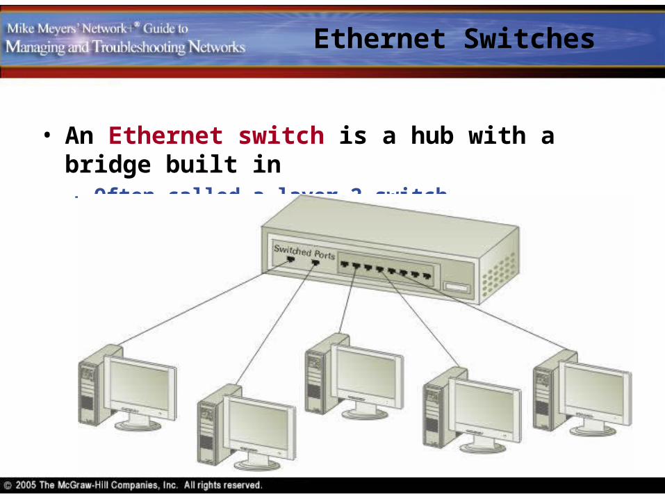
Ethernet Switches
• An Ethernet switch is a hub with a bridge built in– Often called a layer 2 switch

Switched Ethernet
• Ethernet switches may be used to replace hubs for improved performance – resulting in switched Ethernet– Creates point-to-point links between devices to form
single two-node collision domains – essentially eliminating collisions
– Devices get full dedicated bandwidth

Backbone
• A backbone is a segment that connects other segments
• Backbones usually run at higher speeds than other segments

Full-Duplex Ethernet
• Full-duplex means that a device can send and receive data simultaneously
• Ethernet transmissions are half-duplex– At any given time a machine can either send or receive
data but not both
• Switched Ethernet uses different pairs of wires for sending and receiving – allowing for full-duplex communication– Essentially doubles the bandwidth

Full Duplex
• If a card supports full-duplex, its setup program will have an option to switch between half- and full-duplex