Embed Size (px)
Citation preview

SUPPLEMENTAL HEATERMODELS: GGG-8300, GGG-8301, GGG-8302, GGG-8303, GGG-8304
INSTALLATION, OPERATION, & PARTS MANUAL
Part Number: GNA 1411 R1
Revised: 1/3/10
Read this manual before using product. Failure to follow instructions and safety precautions can result in serious injury, death, or property damage. Keep manual for future reference.

This product has been designed and constructed according to general engineering standardsa. Other local regulations may apply and must be followed by the operator. We strongly recommend that all personnel associated with this equipment be trained in the correct operational and safety procedures required for this product. Periodic reviews of this manual with all employees should be standard practice. For your convenience, we include this sign-off sheet so you can record your periodic reviews.
a. Standards include organizations such as the American Society of Agricultural and Biological Engineers, American National Standards Institute, Canadian Standards Association, International Organization for Standardization, and/or others.
Date Employee Signature Employer Signature

SPECIFICATIONS:Design tested to CAN/CGA-3.8-99 for gas-fired equipment for drying farm crops.
Gases: natural or vaporized propane gas
Electrical Rating: 115 volts, 60 Hz, 1 Ph1, less than 3 amps
Input Rating:
1.1 PH = single phase power
Model # CapacityGGG-8300 60,000 btu/hrGGG-8301 100,000 btu/hrGGG-8302 60,000 btu/hrGGG-8303 60,000 btu/hrGGG-8304 100,000 btu/hr
Gas Supply Inlet Pressure Manifold PressureGas Max Min 60,000 btu 100,000 btu
Natural Gas 15 psi 2 psi 8.4” WC 20” WCa
a. WC = inches of water column (27” WC = 1 psi
Propane Gas 50 psi 2 psi 4” WC 8.5” WC


TABLE OF CONTENTS
EDWARDS GROUP - SUPPLEMENTAL HEATER GGG-8300, GGG-8301, GGG-8302, GGG-8303, GGG-8304
1. Introduction .......................................................................................................................... 7
2. Safety First............................................................................................................................ 92.1. General Safety ....................................................................................................... 102.2. Installation Safety ................................................................................................... 112.3. Operational & Maintenance Safety......................................................................... 112.4. Storage Safety........................................................................................................ 112.5. Safety Decal Locations........................................................................................... 11
2.5.1. Decal Installation ...................................................................................... 112.5.2. Decal Locations ........................................................................................ 12
3. Installation .......................................................................................................................... 173.1. Location.................................................................................................................. 173.2. Installation .............................................................................................................. 17
4. Operation ............................................................................................................................ 214.1. Operating Procedures ............................................................................................ 21
4.1.1. Start-Up .................................................................................................... 214.1.2. Break-In .................................................................................................... 224.1.3. Shutdown.................................................................................................. 234.1.4. Flame Inspection ...................................................................................... 23
5. Maintenance & Storage...................................................................................................... 255.1. Maintenance Procedures ....................................................................................... 255.2. Storage Procedure ................................................................................................. 27
6. Troubleshooting ................................................................................................................. 296.1. General................................................................................................................... 296.2. Heater Diagnostic................................................................................................... 29
7. Appendix............................................................................................................................. 337.1. Heater Parts List..................................................................................................... 337.2. Electrical Schematic ............................................................................................... 35
Warranty.................................................................................................................................. 37
GNA 1411 R1 5

EDWARDS GROUP - SUPPLEMENTAL HEATER GGG-8300, GGG-8301, GGG-8302, GGG-8303, GGG-8304
6 GNA 1411 R1
EDWARDS GROUP - SUPPLEMENTAL HEATER 1. INTRODUCTIONGGG-8300, GGG-8301, GGG-8302, GGG-8303, GGG-8304
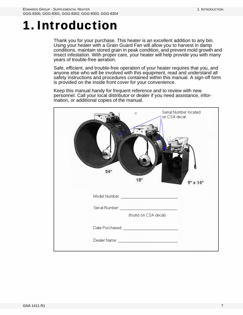
1. IntroductionThank you for your purchase. This heater is an excellent addition to any bin. Using your heater with a Grain Guard Fan will allow you to harvest in damp conditions, maintain stored grain in peak condition, and prevent mold growth and insect infestation. With proper care, your heater will help provide you with many years of trouble-free aeration.
Safe, efficient, and trouble-free operation of your heater requires that you, and anyone else who will be involved with this equipment, read and understand all safety instructions and procedures contained within this manual. A sign-off form is provided on the inside front cover for your convenience.
Keep this manual handy for frequent reference and to review with new personnel. Call your local distributor or dealer if you need assistance, infor-mation, or additional copies of the manual.
GNA 1411 R1 7

1. INTRODUCTION EDWARDS GROUP - SUPPLEMENTAL HEATER GGG-8300, GGG-8301, GGG-8302, GGG-8303, GGG-8304
8 GNA 1411 R1

EDWARDS GROUP - SUPPLEMENTAL HEATER 2. SAFETY FIRSTGGG-8300, GGG-8301, GGG-8302, GGG-8303, GGG-8304
2. Safety FirstThe Safety Alert symbol to the left identifies important safety messages on the product and in the manual. When you see this symbol, be alert to the possibil-ity of personal injury or death. Follow the instructions in the safety messages. Why is SAFETY important to you?
Three big reasons:
• Accidents disable and kill.• Accidents cost.• Accidents can be avoided.
SIGNAL WORDS
Note the use of the signal words DANGER, WARNING, CAUTION, and NOTICE with the safety messages. The appropriate signal word for each message has been selected using the definitions below as a guideline.
The Safety Alert symbol means ATTENTION, BE ALERT!, YOUR SAFETY IS INVOLVED.
DANGER
Indicates an imminently hazardous situation that, if not avoided, will result in serious injury or death.
WARNING
Indicates a hazardous situation that, if not avoided, could result in serious injury or death.
CAUTION
Indicates a hazardous situation that, if not avoided, may result in minor or moderate injury.
NOTICEIndicates a potentially hazardous situation that, if not avoided, may result in property damage.
GNA 1411 R1 9
2. SAFETY FIRST EDWARDS GROUP - SUPPLEMENTAL HEATER2.1. GENERAL SAFETY GGG-8300, GGG-8301, GGG-8302, GGG-8303, GGG-8304
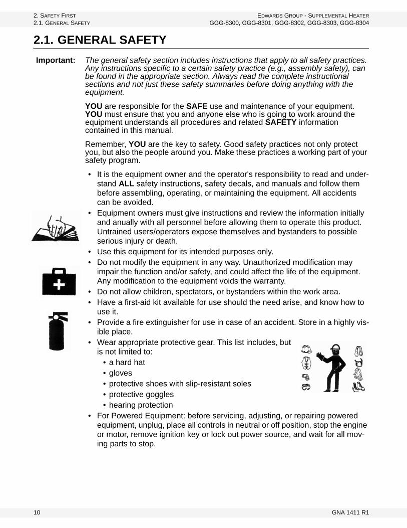
2.1. GENERAL SAFETYImportant: The general safety section includes instructions that apply to all safety practices.
Any instructions specific to a certain safety practice (e.g., assembly safety), can be found in the appropriate section. Always read the complete instructional sections and not just these safety summaries before doing anything with the equipment.
YOU are responsible for the SAFE use and maintenance of your equipment. YOU must ensure that you and anyone else who is going to work around the equipment understands all procedures and related SAFETY information contained in this manual.
Remember, YOU are the key to safety. Good safety practices not only protect you, but also the people around you. Make these practices a working part of your safety program.
• It is the equipment owner and the operator's responsibility to read and under-stand ALL safety instructions, safety decals, and manuals and follow them before assembling, operating, or maintaining the equipment. All accidents can be avoided.
• Equipment owners must give instructions and review the information initially and anually with all personnel before allowing them to operate this product. Untrained users/operators expose themselves and bystanders to possible serious injury or death.
• Use this equipment for its intended purposes only.• Do not modify the equipment in any way. Unauthorized modification may
impair the function and/or safety, and could affect the life of the equipment. Any modification to the equipment voids the warranty.
• Do not allow children, spectators, or bystanders within the work area.• Have a first-aid kit available for use should the need arise, and know how to
use it.• Provide a fire extinguisher for use in case of an accident. Store in a highly vis-
ible place.• Wear appropriate protective gear. This list includes, but
is not limited to:• a hard hat• gloves• protective shoes with slip-resistant soles• protective goggles• hearing protection
• For Powered Equipment: before servicing, adjusting, or repairing powered equipment, unplug, place all controls in neutral or off position, stop the engine or motor, remove ignition key or lock out power source, and wait for all mov-ing parts to stop.
10 GNA 1411 R1

EDWARDS GROUP - SUPPLEMENTAL HEATER 2. SAFETY FIRSTGGG-8300, GGG-8301, GGG-8302, GGG-8303, GGG-8304 2.2. INSTALLATION SAFETY
• Follow good shop practices:• keep service area clean and dry• be sure electrical outlets and tools are properly
grounded• use adequate light for the job at hand• Think SAFETY! Work SAFELY!
2.2. INSTALLATION SAFETY• Check all equipment for damage immediately upon arrival. Do not attempt to
install a damaged item.• Have 2 people handle the heavy, bulky components.
2.3. OPERATIONAL & MAINTENANCE SAFETY• Ensure that electrical cords are in good condition; replace if necessary.• Ensure the fan inlet is not plugged with any foreign material. • Keep inlet screen in place at all times.• Before resuming work, install and secure all guards. Keep guards in good
working order.• Ensure parts are in good condition and installed properly.
• Do not operate heater with natural gas if valve is on propane setting.• Use vaporized propane only.• Do not tamper with or try to adjust pressure regulator.
2.4. STORAGE SAFETY• Store the unit in a dry, clean area away from human activity.• Do not permit children to play on or around the stored machine.
2.5. SAFETY DECAL LOCATIONS• Keep safety decals clean and legible at all times.• Replace safety decals that are missing or have become illegible. See decal
location figures below.• Replaced parts must display the same decal(s) as the original part.• Safety decals are available from your distributor, dealer, or factory.
2.5.1. DECAL INSTALLATION
1. Decal area must be clean and dry, with a temperature above 10°C (50°F).2. Decide on the exact position before you remove the backing paper.3. Align the decal over the specified area and carefully press the small portion
with the exposed sticky backing in place.
GNA 1411 R1 11
2. SAFETY FIRST EDWARDS GROUP - SUPPLEMENTAL HEATER2.5. SAFETY DECAL LOCATIONS GGG-8300, GGG-8301, GGG-8302, GGG-8303, GGG-8304
4. Slowly peel back the remaining paper and carefully smooth the remaining portion of the decal in place.
5. Small air pockets can be pierced with a pin and smoothed out using the sign backing paper.
2.5.2. DECAL LOCATIONS
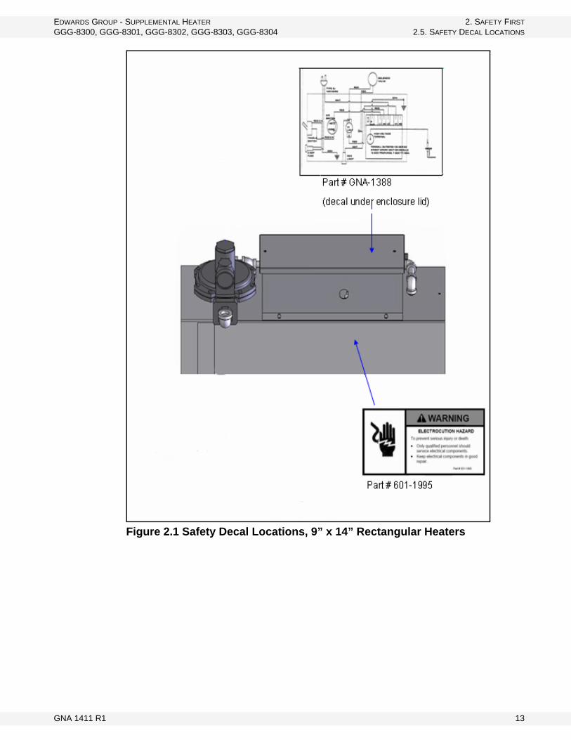
Replicas of the safety decals that are attached to the equipment are shown below. Good safety requires that you familiarize yourself with the various safety decals and the areas or particular functions that the decals apply to as well as the safety precautions that must be taken to avoid serious, injury, death, or damage.
12 GNA 1411 R1
EDWARDS GROUP - SUPPLEMENTAL HEATER 2. SAFETY FIRSTGGG-8300, GGG-8301, GGG-8302, GGG-8303, GGG-8304 2.5. SAFETY DECAL LOCATIONS
Figure 2.1 Safety Decal Locations, 9” x 14” Rectangular Heaters
GNA 1411 R1 13

2. SAFETY FIRST EDWARDS GROUP - SUPPLEMENTAL HEATER2.5. SAFETY DECAL LOCATIONS GGG-8300, GGG-8301, GGG-8302, GGG-8303, GGG-8304
Figure 2.2 Safety Decal Locations, 9” x 14” Rectangular Heater
14 GNA 1411 R1

EDWARDS GROUP - SUPPLEMENTAL HEATER 2. SAFETY FIRSTGGG-8300, GGG-8301, GGG-8302, GGG-8303, GGG-8304 2.5. SAFETY DECAL LOCATIONS
Figure 2.3 Safety Decal Locations, 8” x 24” Round Heater
GNA 1411 R1 15

2. SAFETY FIRST EDWARDS GROUP - SUPPLEMENTAL HEATER2.5. SAFETY DECAL LOCATIONS GGG-8300, GGG-8301, GGG-8302, GGG-8303, GGG-8304
Figure 2.4 Safety Decal Locations, 18” x 24” Round Heater
16 GNA 1411 R1

EDWARDS GROUP - SUPPLEMENTAL HEATER 3. INSTALLATIONGGG-8300, GGG-8301, GGG-8302, GGG-8303, GGG-8304 3.1. LOCATION
3. Installation
This heater is designed solely for use as a low temperature heater for drying farm crops. Alteration or use of this heater for any other application will void warranty.
The installation and operation of this heater shall be in accordance with the current INSTALLATION CODES FOR GAS BURNING APPLIANCES AND EQUIPMENT, CAN1-B149.1 and B149.2 or applicable Provincial Regulations that should be carefully followed in all cases. Authorities having jurisdiction should be consulted before installation.
3.1. LOCATION
Location for the heater:
• The heater must be installed on a non-combustible level surface.• The heater must be located as close to the bin as possible (leave 8” to 12” or
more for routine servicing and inspection).• Provide adequate drainage to protect the heater from water damage.• Ensure that the aeration fan has adequate capacity for the heater and grain
bin size. • The fan should be 1hp for every 1000 bushels.
• 60,000 BTU heater = 3 hp fan only• 100,000 BTU heater = 5-7 hp fan only
• Heater and fan should be positioned opposite of the unload auger. If there are multiple fans and heaters being used, they should be opposite of the unload auger and no further than 90° apart.
Important: Ensure the heater is mounted so that the control box is positioned towards the top.
3.2. INSTALLATION1. Install the heater in a horizontal position between the outlet of the aeration
fan and the inlet of the air distribution system of the grain bin. Make sure the unit is installed with the burner end closest to the aeration fan.
Warning: Before continuing, please reread the safety information relevant to this section at the beginning of this manual. Failure to follow the safety instructions can result in serious injury, death, or property damage.
Flat Bottom Bins Ensure heater is level with the fan and that both are ade-quately supported.
Hopper Bottom Bins Ensure there is adequate support for both the heater and the fan.
GNA 1411 R1 17
3. INSTALLATION EDWARDS GROUP - SUPPLEMENTAL HEATER3.2. INSTALLATION GGG-8300, GGG-8301, GGG-8302, GGG-8303, GGG-8304
a. For the 9” x 14” rectangular heaters: Slip the collared end over the aeration inlet on the bin. Fasten units together by inserting metal screws through the holes on the collar of the heater. Next, slip the aeration fan as far as possible into the inlet end of the heater. Secure with metal screws through the holes in the heater shell.
b. For the 18” and 24” round heaters: Simply bolt unit to the flanged inlet of the bin inlet port using 3/8" bolts and locknuts.
2. The bottom of the fan's air intake must be at least 12" above ground to prevent it from drawing debris into the fan and heater.
3. Connect heater to the appropriate gas supply; ensure that the gas pressure at the inlet of the heater is within the specified range. The heater will not run on gas that is supplied under 2 psi. The recommended hose size for connection to a propane cylinder is a 1/4" gas hose assembly and for natural gas a 3/8" gas hose assembly.
Important: The person who installs and maintains this heater must carefully read and under-stand the instructions contained in this manual. This person should be certified to work with electrical and gas equipment.
4. Visually inspect the hose assembly and ensure that it is protected from traffic. If there is excessive abrasion, wear, or if the hose is cut, it must be replaced.
5. Ensure that there is no LP-gas container (liquid propane) closer than 6’ from the heater and allow for the following clearances to any other combustible materials:
• Floor: 0• Sides: 1’ • Top: 2’
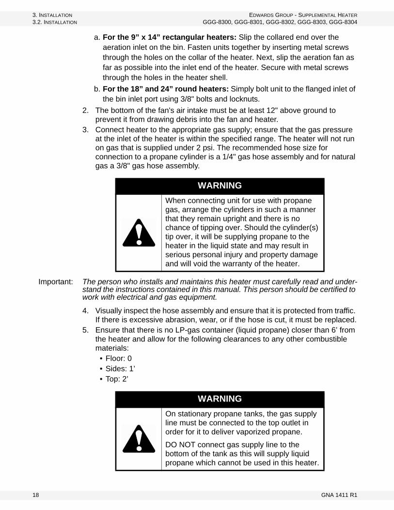
WARNINGWhen connecting unit for use with propane gas, arrange the cylinders in such a manner that they remain upright and there is no chance of tipping over. Should the cylinder(s) tip over, it will be supplying propane to the heater in the liquid state and may result in serious personal injury and property damage and will void the warranty of the heater.
WARNINGOn stationary propane tanks, the gas supply line must be connected to the top outlet in order for it to deliver vaporized propane.
DO NOT connect gas supply line to the bottom of the tank as this will supply liquid propane which cannot be used in this heater.
18 GNA 1411 R1

EDWARDS GROUP - SUPPLEMENTAL HEATER 3. INSTALLATIONGGG-8300, GGG-8301, GGG-8302, GGG-8303, GGG-8304 3.2. INSTALLATION
6. After installation, open the gas supply to the heater and check all hose connections for gas leaks by applying a mild soap and water solution to the connections. Remember to turn off gas supply after checking.
7. Connect the heater to an adequate 115 V electrical supply as specified on the rating plate. For protection against shock hazard, the supply cord must be plugged directly into a grounded, 3-wire extension cord (if required). This cord must be plugged into a grounded 3-prong receptacle. The extension cord should be a minimum of 14-2.
Important: Do not use heater if propane is below 20% full. Low propane levels could create carboning in heater.
WARNING
This unit is for outdoor installation only.
GNA 1411 R1 19

3. INSTALLATION EDWARDS GROUP - SUPPLEMENTAL HEATER3.2. INSTALLATION GGG-8300, GGG-8301, GGG-8302, GGG-8303, GGG-8304
20 GNA 1411 R1

EDWARDS GROUP - SUPPLEMENTAL HEATER 4. OPERATIONGGG-8300, GGG-8301, GGG-8302, GGG-8303, GGG-8304 4.1. OPERATING PROCEDURES
4. Operation
4.1. OPERATING PROCEDURES.
4.1.1. START-UP
1. Open all roof vents and ensure that they are not obstructed.
2. Check aeration fan inlet and maker sure there are no obstructions.3. Connect unit to appropriate gas supply (propane or natural gas).4. Connect unit to 115 V power supply.5. Set the gas selector valve to the gas being used (see Figure 4.1). This
conversion should be done before the aeration fan is started.6. Open gas supply at the source (propane cylinder valve or natural gas supply
line valve).7. Open gas shut off valve on heater (see figure below).8. Turn aeration fan on.9. Move toggle switch to ON position.10. Unit will pre-purge for 15 seconds, then red light will come on as the heater
attempts to light. If red light fails to remain on longer than 10 seconds, turn switch to OFF position and repeat step 8 through 10 (red light should remain on while heater is lit).
11. To shut down, close gas shut off valve and move toggle switch to the OFF position.
12. If unit is not to be used for an extended period of time, disconnect power and shut off gas valve on heater and gas supply valve.
Warning: Before continuing, please reread the safety information relevant to this section at the beginning of this manual. Failure to follow the safety instructions can result in serious injury, death, or property damage.
WARNING
The area around the heater should be kept clear and free from combustible materials and other flammable liquids.
NOTICEIf there is a chance of the roof vents freezing, do not operate the heater.
GNA 1411 R1 21

4. OPERATION EDWARDS GROUP - SUPPLEMENTAL HEATER4.1. OPERATING PROCEDURES GGG-8300, GGG-8301, GGG-8302, GGG-8303, GGG-8304
Note: If heater fails to light and/or function properly, see the troubleshooting section.
Figure 4.1 Gas Valving
4.1.2. BREAK-IN
Although there are no operational restrictions on the unit when used for the first time, it is recommended that the following items be checked:
Before starting:
• Read the aeration fan operation manual.• During the first few minutes of operation, ensure that the unit is running
properly.
After operating for 5 and 10 hours:
• Check that all guards are installed and working properly.
WARNING
When heater is not in use, shut off gas valve on heater and at gas source.
WARNING
When using propane, gas selector valve must be at the PROPANE position. Failure to heed could cause serious injury or death.
22 GNA 1411 R1

EDWARDS GROUP - SUPPLEMENTAL HEATER 4. OPERATIONGGG-8300, GGG-8301, GGG-8302, GGG-8303, GGG-8304 4.1. OPERATING PROCEDURES
4.1.3. SHUTDOWN
1. Close propane/natural gas valve at tank/hydrant.2. Allow heater to run until the flame burns out. This purges the gas out of the
heater plumbing.3. Close gas valve on heater.4. Turn off and unplug heater.5. Allow aeration fan to operate for at least 2 minutes to cool heater down, then
shut off fan.
4.1.4. FLAME INSPECTION
This heater uses a flame generation system that must be functioning correctly in order for the heater to produce the specified BTUs.
1. Inspect the flame through the viewing window on the side of the heater (Figure 4.2). The flame should look blue with an orange tip approximately 2” to 2-1/2” long.
2. If the flame is all blue and short, then the airflow is too high. Either add more grain to the bin to increase the static pressure (lower air flow) or use a smaller aeration fan with less air flow.
3. If the flame is yellowish and long, then airflow is too low. First, ensure that there aren’t any restrictions in gas flow and that the valves are set correctly. If problem remains, either remove grain from the bin to increase air flow or use a larger fan.
Figure 4.2 Flame Viewing Window
GNA 1411 R1 23

4. OPERATION EDWARDS GROUP - SUPPLEMENTAL HEATER4.1. OPERATING PROCEDURES GGG-8300, GGG-8301, GGG-8302, GGG-8303, GGG-8304
24 GNA 1411 R1
EDWARDS GROUP - SUPPLEMENTAL HEATER 5. MAINTENANCE & STORAGEGGG-8300, GGG-8301, GGG-8302, GGG-8303, GGG-8304 5.1. MAINTENANCE PROCEDURES
5. Maintenance & Storage
5.1. MAINTENANCE PROCEDURES
YEARLY MAINTENANCE
The following maintenance should be performed before the heater is used at the beginning of each season.
1. Check burner to ensure that it is not plugged with foreign material. If necessary, remove material and use a small wire brush or acetylene tip cleaners to clean the ports in the burner housing.
2. Examine electrode gap and ensure it is 3/16”. Adjust if necessary. Replace electrode if corroded.
3. Check all plumbing joints for leaks. Use a mixture of water and mild soap and spray on the joints. If bubbling occurs, a leak exists and the fitting needs to be tightened or replaced.
4. Check all wires and connections. Replace if required.
ELECTRICAL MAINTENANCE
All electrical components are in the electrical box on the top of the heater (see figure below).
The electrical components should not require any maintenance.
Warning: Before continuing, please reread the safety information relevant to this section at the beginning of this manual. Failure to follow the safety instructions can result in serious injury, death, or property damage.
WARNING
Before performing any maintenance on this unit, lock out power source and shut off gas valves on heater and tank.
WARNING
When servicing gas components, keep sparks or other ignition sources away from the area.
GNA 1411 R1 25

5. MAINTENANCE & STORAGE EDWARDS GROUP - SUPPLEMENTAL HEATER5.1. MAINTENANCE PROCEDURES GGG-8300, GGG-8301, GGG-8302, GGG-8303, GGG-8304
Figure 5.1 Pressure Regulator and Electrical Box
PRESSURE REGULATOR MAINTENANCE
This heater contains a pressure regulator on top of the unit (see figure below). This regulator is preset at the factory and does not require any adjustment of any kind.
Ensure vent screen is clear at all times. Note: Any tampering with the regulator voids the warranty.
Figure 5.2 Solenoid Valve Location
SOLENOID VALVE MAINTENANCE
The solenoid valve does not require any maintenance.
26 GNA 1411 R1

EDWARDS GROUP - SUPPLEMENTAL HEATER 5. MAINTENANCE & STORAGEGGG-8300, GGG-8301, GGG-8302, GGG-8303, GGG-8304 5.2. STORAGE PROCEDURE
5.2. STORAGE PROCEDUREIf unit is to be stored outside, the heater should be covered with a tarp or other protective cover. Ensure that unit is disconnected from the electrical power source and gas supply.
If unit is to be stored inside, ensure that the heater is placed in a dry location and away from anything that may damage the unit.
GNA 1411 R1 27

5. MAINTENANCE & STORAGE EDWARDS GROUP - SUPPLEMENTAL HEATER5.2. STORAGE PROCEDURE GGG-8300, GGG-8301, GGG-8302, GGG-8303, GGG-8304
28 GNA 1411 R1

EDWARDS GROUP - SUPPLEMENTAL HEATER 6. TROUBLESHOOTINGGGG-8300, GGG-8301, GGG-8302, GGG-8303, GGG-8304 6.1. GENERAL
6. TroubleshootingNote: See the appendix for parts and electrical diagram details.
6.1. GENERAL1. Move toggle switch to ON position.2. After 15 second delay (pre-purge), the red light on the side of the control box
should come on, the solenoid valve should click open, the igniter inside the burner should spark, and the unit should light within 8 seconds.
3. If unit does not light within 8 seconds, reset by turning toggle switch to OFF. Then, try again.
6.2. HEATER DIAGNOSTIC1. Check the 2 amp fuse.
• Replace if necessary.2. Check for voltage across the toggle switch.
• If there is no voltage present, replace the switch.3. Check for voltage across the air switch.
• If there is no voltage, then the switch is not closing. This may be caused by a defective switch or by not enough static pressure in the bin.
• Replace air switch if defective; if not, bin needs to be filled with more grain.
Note: Heater needs a minimum of 1” static pressure to function.
4. Check for power on L1.• There should be voltage present here but not on V1. • If spark does not come on 15 seconds after the toggle switch has been
turned on, or if the solenoid valve does not click loudly, then the circuit board is defective and needs replacing.
5. Check for voltage across the red light. • If voltage is present then light is defective and needs replacing.
6. Check the hi-limit switch. • If there is power on the side with the 2 wires but no power on the single
wire side, then limit switch is open. The switch is either defective or has overheated and tripped out. Let aeration fan run for 2 minutes to cool unit off.
• If there is still no power present on other side, replace limit switch.7. Check voltage going to the solenoid valve.
• If there is power going to the valve but it is not snapping open, then valve is defective and needs to be replaced.
• If valve is opening and spark is present, then there is a problem with the gas supply.
GNA 1411 R1 29

6. TROUBLESHOOTING EDWARDS GROUP - SUPPLEMENTAL HEATER6.2. HEATER DIAGNOSTIC GGG-8300, GGG-8301, GGG-8302, GGG-8303, GGG-8304
• Check to see if the gas shut off valves are all open or if hose is pinched off.
HEATER DOES NOT STARTCause SolutionBurnt out fuse • Replace with 2 amp fuse.No grain or not enough in bin
• Add more grain to bin and ensure that aeration duct is covered by at least 3’ of grain.
Defective switch • Test for 120 V across switch leads.
Defective air switch • Test for 120 V downstream side. If there is no voltage, replace air switch.
Defective DSI module• Test for 120 V at terminal L1 on direct spark ignition (DSI) module.
If voltage is present there and if there is no spark, power at termi-nal V1 module is defective.
RED LIGHT COMES ON, BUT FLAME DOES NOT IGNITECause Solution
No spark• Check for spark during ignition cycle by sliding ignition wire terminal off the
coil tower on the DSI module and holding it 3/16” from coil terminal. If spark does not arc across gap, DSI is faulty and should be replaced.
Faulty solenoid • Check for 120 V between terminals V1 and V2 on DSI module; if present, replace solenoid.
Gas supply insuffi-cient
• With propane, ensure that the regulator on the tank is supplying gas within the specified range, and that gas is being drawn off the top of the tank.
• Check for frost on any fittings.• With natural gas, ensure that the supply pressure to the heater is over 2
psi. The minimum size of the gas supply hose/pipe should be 3/8”.• Check for gas supply by removing 1/8” pipe plug from gas valve train;
there should be a steady flow of gas when heater is trying to light. Other-wise, check for gas flow at upstream fittings and correct.
Incorrect air supply• Block off air intake 30% to 50% and try to light; if heater lights, then the air-
flow is too high. Correct by adding more grain to the bin or using a smaller fan.
30 GNA 1411 R1

EDWARDS GROUP - SUPPLEMENTAL HEATER 6. TROUBLESHOOTINGGGG-8300, GGG-8301, GGG-8302, GGG-8303, GGG-8304 6.2. HEATER DIAGNOSTIC
HEATER LIGHTS BUT STOPS IN LESS THAN 8 SECONDSCause Solution
Too much air• If flame is very blue and burning inside the burner body, restrict air-
flow by 50%. If flame gets longer and more orange, then add more grain to the bin or use a smaller fan.
Not enough air • If flame is very yellowish and burning outside the burner body, then use a larger fan or remove some grain from the bin.
Gas supply insufficient
• With propane, ensure that the regulator on the tank is supplying gas within the specified range, and that gas is being drawn off the top of the tank.
• With natural gas, ensure that the supply pressure to the heater is over 2 psi. The minimum size of gas supply hose/pipe should be 3/8”.
• Check for frost on any fittings. • Check gas supply by removing 1/8” pipe plug from gas valve train.
There should be a steady flow of gas when heater is trying to light. Otherwise, check for gas flow at upstream fittings and correct.
HEATER LIGHTS AND RUNS 8 SECONDSCause Solution
Reversed polarity• The DSI module is polarity sensitive. If reversed, then the incoming
power cord wires need to be switched. Switch the wires on the extension cord or at the receptacle.
HEATER RUNS FOR OVER 30 SECONDS AND THEN GOES OUTCause Solution
Too much air• If flame is very blue and burning inside the burner body, restrict air-
flow by 50%. If flame gets longer and more orange, then add more grain to the bin or use smaller fan.
Not enough air • If flame is very yellowish and burning outside the burner body, then use a larger fan or remove some grain from the bin.
Poor ground • Ensure that heater has good continuity through the ground wire; if not, correct.
Gas supply insufficient
• With propane, ensure that the regulator on the tank is supplying gas within the specified range, and that gas is being drawn off the top of the tank.
• With natural gas, ensure that the supply pressure to the heater is over 2 psi. The minimum size of gas supply hose/pipe should be 3/8”.
• Check for frost on any fittings.• Check for gas supply by removing 1/8” pipe plug from gas valve
train. There should be a steady flow of gas when heater is trying to light. Otherwise, check for gas flow at upstream fittings and cor-rect.
GNA 1411 R1 31

6. TROUBLESHOOTING EDWARDS GROUP - SUPPLEMENTAL HEATER6.2. HEATER DIAGNOSTIC GGG-8300, GGG-8301, GGG-8302, GGG-8303, GGG-8304
32 GNA 1411 R1

EDWARDS GROUP - SUPPLEMENTAL HEATER 7. APPENDIXGGG-8300, GGG-8301, GGG-8302, GGG-8303, GGG-8304 7.1. HEATER PARTS LIST
7. Appendix7.1. HEATER PARTS LIST
GNA 1411 R1 33

7. APPENDIX EDWARDS GROUP - SUPPLEMENTAL HEATER7.1. HEATER PARTS LIST GGG-8300, GGG-8301, GGG-8302, GGG-8303, GGG-8304
34 GNA 1411 R1
EDWARDS GROUP - SUPPLEMENTAL HEATER 7. APPENDIXGGG-8300, GGG-8301, GGG-8302, GGG-8303, GGG-8304 7.2. ELECTRICAL SCHEMATIC
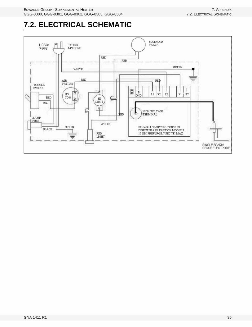
7.2. ELECTRICAL SCHEMATIC
GNA 1411 R1 35

7. APPENDIX EDWARDS GROUP - SUPPLEMENTAL HEATER7.2. ELECTRICAL SCHEMATIC GGG-8300, GGG-8301, GGG-8302, GGG-8303, GGG-8304
36 GNA 1411 R1
WARRANTYExcept as expressly provided in this agreement, Edwards Group (hereinafter called the Manu-facturer) excludes all express or implied warranties, conditions, and obligations of the Manufac-turer, whether statutory or otherwise, concerning the quality of the units or their fitness for any purpose.
Under no circumstances will the Manufacturer be liable for any kind of special, consequential, indirect, or incidental damages resulting from the use of its products, nor shall the Manufac-turer's liability ever exceed the selling price of the product.
Edwards Group warrants their products as follows:
1. Goods free from defect:a. The unit shall be free from defects in materials and workmanship and shall operate
properly in accordance with industry standards when employed in normal usage, provided the unit has been properly installed for a period of: one (1) year from the original date of purchase.
2. The warranty does not include:a. Routine replacement of parts due to normal wear and tear arising from use.b. Any defect attributable in whole or in part to misuse or improper installation.c. Any damage or defect attributable to repair of the unit outside the Manufacturer's facilities
or those of an authorized dealer, or the installation of unapproved parts on the unit in the Manufacturer's judgment to affect it's performance or reliability, or which has been subject to misuse, negligence, or accident.
d. Any damage attributable to accident or to lightning, power surge, brownout, leaking, damage, or connection to a power source having a greater rating than that specified in the unit specifications.
3. Repair or Replacement
Where any part of the unit fails during normal usage during the warranty period specified, the Manufacturer, or authorized dealer of the Manufacturer, shall repair or replace the defective part of the unit with a new or factory reconditioned part, such replacement or repair to be made with-out charge for parts or labor, F.O.B. the Manufacturer.
4. Warranties shall not apply to any product made by the Manufacturer that has not been operated in accordance with the Manufacturer's printed instructions or shall have been operated beyond the rated capacity of the product or a use not intended.
5. The Manufacturer reserves the right to make design or specification changes at any time, without contingent obligation to purchasers of products already sold.
WARRANTY VOID IF NOT REGISTERED

Edwards Group is a Division of Ag Growth Industries LP
Part of the Ag Growth International Inc. Group
P.O. Box 1600
Lethbridge, Alberta, Canada T1J 4K3
Phone: (403) 320-5585
Fax: (403) 320-5668
Toll Free: (800) 565-2840 (Canada & USA)
Website: www.edwardsgroup.ca
© Ag Growth Industries Limited Partnership 2009