Embed Size (px)
Citation preview

ModelsMT128ISA-UV, MT128PCI-SD, MT128PCI-SV
User Guide

User GuideP/N 88300350
Models MT128ISA-UV, MT128PCI-SDMT128PCI-SV
Copyright© 2000 by Multi-Tech Systems, Inc.
All rights reserved. This publication may not be reproduced, in whole or in part, without prior writtenpermission from Multi-Tech Systems, Inc.
Multi-Tech Systems, Inc. makes no representations or warranties with respect to the contents hereofand specifically disclaims any implied warranties of merchantability or fitness for any particular pur-pose. Furthermore, Multi-Tech Systems, Inc. reserves the right to revise this publication and to makechanges from time to time in the content hereof without obligation of Multi-Tech Systems, Inc. to notifyany person or organization of such revisions or changes.
Revision DescriptionA Manual released at Revision A.
(1/15/1998)
B Manual revised to include updates for driver version ( version 2.52 for Windows 95, 98, NTand version 3.40 for WIndows 2000), PCI adapter support, Windows 98 and Windows 2000installation instructions.
(1/20/2000)
Trademarks
MultiModem, MultiModemISDN, Multi-Tech, and the Multi-Tech logo are trademarks of Multi-TechSystems, Inc.
AT&T is a registered trademark and 5ESS is a trademark of American Telephone and Telegraph.Microsoft, Windows, Windows 95, Windows 98, Windows NT and Windows 2000 are either registeredtrademarks or trademarks of Microsoft Corporation in the United States and/or other countries. Allother trademarks are owned by their respective companies.
Multi-Tech Systems, Inc.2205 Woodale Drive
Mounds View, Minnesota 55112 U.S.A.(612) 785-3500 or (800) 328-9717
U. S. FAX 612-785-9874Technical Support (800) 972-2439
Internet Address: http://www.multitech.com

ContentsChapter 1 - Introduction and Description .................................................................................................... 6Product Overview ....................................................................................................................................... 7
Introduction .......................................................................................................................................... 7Product Description .............................................................................................................................. 7Features ............................................................................................................................................... 8What Is in Your MultiModemISDN Package? ....................................................................................... 8
Manual Organization .................................................................................................................................. 9Chapter 1 – Introduction and Description ............................................................................................. 9Chapter 2 – Installation ........................................................................................................................ 9Chapter 3 – AT Commands .................................................................................................................. 9Chapter 4 – Troubleshooting ................................................................................................................ 9Chapter 5 – Warranty, Service, and Technical Support ........................................................................ 9Appendices .......................................................................................................................................... 9
Technical Specifications ........................................................................................................................... 10Chapter 2 - Installation ............................................................................................................................... 11Installation - Introduction ........................................................................................................................... 12
ISDN BRI Line .................................................................................................................................... 12SPID (Service Profile ID) .................................................................................................................... 12NT1 Connection ................................................................................................................................. 12Internet Access .................................................................................................................................. 14Safety Warnings ................................................................................................................................. 14Environment Setup............................................................................................................................. 14
Hardware Installation ................................................................................................................................ 15Software Installation ................................................................................................................................. 17
Before You Begin ............................................................................................................................... 17Determining your modem type ........................................................................................................... 18Configuring for Your ISDN Switch ...................................................................................................... 19
Windows 3.1 Installation and Configuration .............................................................................................. 20 Windows 3.1 Application Interface Setup .......................................................................................... 21Windows 3.1 Removal of the ISDN Drivers ........................................................................................ 21
Windows 95 Installation and Configuration ............................................................................................... 22Windows 95 and the NDISWAN interface .......................................................................................... 23Windows 95 Single Channel Access (NDISWAN) ............................................................................. 24Windows 95 Multilinked Channel Access (NDISWAN) ....................................................................... 26Windows 95 and the VCOMM (Virtual Modem) Interface ................................................................... 26Windows 95 Single Channel Access (VCOMM) ................................................................................. 28Windows 95 Multilinked Channel Access (VCOMM) ......................................................................... 29Windows 95 and the CAPI Interface.................................................................................................. 30Windows 95 Multilinked Channel Access (CAPI) ............................................................................... 31Windows 95 Removal of the ISDN Driver ........................................................................................... 32
Windows 98 Installation and Configuration ............................................................................................... 33Windows 98 Single Channel Access (NDISWAN) ............................................................................. 34Windows 98 Multilinked Channel Access (NDISWAN) ....................................................................... 35Windows 98 and the VCOMM (Virtual Modem) Interface ................................................................... 36 Windows 98 Single Channel Access (VCOMM) ................................................................................ 36Windows 98 Multilinked Channel Access (VCOMM) .......................................................................... 37Windows 98 and the CAPI Interface .................................................................................................. 38Windows 98 Single Channel Access (CAPI) ...................................................................................... 38Windows 98 Multilinked Channel Access (CAPI) ............................................................................... 39Windows 98 Removal of the ISDN Drivers ......................................................................................... 40

Windows NT Installation and Configuration .............................................................................................. 41Windows NT Single Channel Access (NDISWAN) ............................................................................. 44Windows NT Multilinked Channel Access (NDISWAN) ...................................................................... 44Windows NT and the CAPI Interface .................................................................................................. 46Windows NT Single Channel Access (CAPI) ...................................................................................... 47Windows NT Multilinked Channel Access (CAPI) ............................................................................... 48Windows NT Removal of the ISDN Drivers ........................................................................................ 48Windows 2000 Installation and Configuration ..................................................................................... 49Windows 2000 Single Channel Access (NDISWAN) .......................................................................... 52
Windows 2000 Multilinked Access (NDISWAN) ........................................................................................ 53Windows 2000 and the CAPI Interface ............................................................................................... 54
Windows 2000 Single Channel Access (CAPI) ......................................................................................... 54Windows 2000 Multilinked Channel Access (CAPI) ............................................................................ 55ISDN Monitor, ISDN Line Test Tool and Driver Configuration ............................................................. 55
Windows 2000 POTS/Voice Port Configuration ....................................................................................... 58Windows 2000 Removal of the ISDN Drivers ......................................................................................... 59
Chapter 3 - AT Commands ................................................................................................................. 60AT COMMANDS ................................................................................................................................ 61Introduction ........................................................................................................................................ 61Commands and Descriptions ............................................................................................................. 61Chapter 4 - Troubleshooting ............................................................................................................... 63Troubleshooting ................................................................................................................................. 64Introduction ........................................................................................................................................ 64Frequently Asked Questions .............................................................................................................. 64
LineTest .................................................................................................................................................... 68ISDN LOG ................................................................................................................................................ 68Chapter 5 - Warranty, Service and Technical Support ............................................................................... 71
Warranty, Service and Technical Support ........................................................................................... 72Limited Warranty ...................................................................................................................................... 72
On-line Warranty Registration ............................................................................................................ 72Technical Support ............................................................................................................................... 72Recording TA Information ................................................................................................................... 72Contacting Technical Support via E-Mail ............................................................................................ 73
Service ..................................................................................................................................................... 73About the Internet: .................................................................................................................................... 74Ordering Accessories ............................................................................................................................... 74Appendices ............................................................................................................................................... 75Appendix A - Regulatory Agency Information ............................................................................................ 76FCC Part 68 Telecom Digital .................................................................................................................... 76Class B Statement .................................................................................................................................... 77Appendix B - APIs ................................................................................................................................... 79Appendix C - Applications ........................................................................................................................ 81TRUMPET Setup through COM Port Emulation ....................................................................................... 81Microsoft HyperTerminal ........................................................................................................................... 83RVS-COM Lite .......................................................................................................................................... 84Index ........................................................................................................................................................ 85

Chapter 1 - Introduction and Description

Chapter 1 - Introduction and Description
7MT128ISA/PCI
Product Overview
Introduction
Welcome to the world of ISDN communications. You have acquired one of the finest ISDNterminal adapters (TAs) available today, the MultiModemISDN from Multi-Tech Systems.
The proliferation of PCs and LANs with bandwidth-intensive applications has generated apowerful demand for high-speed connections. The worldwide standardization of ISDN,combined in many countries with its growing availability and falling cost, make it a naturalchoice for enhancing data throughput. Terminal adapters provide high-performance solutionsfor Internet access, file transfer, remote access service (RAS), and running existing modemapplications through the ISDN network.
Product Description
The MT128ISA and MT128PCI are internal PC cards for IBM personal computers; and fit intoa full-or half-sized expansion slot. There are two ISDN interface options, ST and U. If youpurchased the ST interface adapter (MT128PCI-SD/SV), you need an ISDN NT1deviceconnection to the ISDN switch. If you purchased the U interface adapter (MT128ISA-UV), itcan directly connect to the ISDN switch (figure 1-1).
ISDN central office
custom er site
NT1
ISDN U interfa
ce
T interfaceISDN
ISDN U interface
I-IN100-U
I-IN100-ST
custom er site
Figure 1-1. ”ST” and “U” Interface Options
Your internal ISDN PC card is compatible with prevalent ISDN switch protocols. Itcommunicates using ISDN BRI (2B+D) service, which provides up to 128K bps datacommunications.
This manual documents the following models:
• MT128PCI-SD for ST interface no POTS port• MT128PCI-SV for ST interface with one POTS port• MT128ISA-UV for U interface with one POTS port
All of the current analog devices, including telephone set, G3 fax, answering machine,modem, and PBX trunk line, can be connected to the POTS port via an RJ-11 jack in “V”models.
This User Guide will help you install, configure, and operate your terminal adapter.

8
MultiModemISDN User Guide
MT128ISA/PCI
Features
Your internal ISDN PC card features include:
• D Channel protocols including AT&T 5ESS, Nortel DMS-100, US NI-1 & NI2, ETSI andJapan INS-64.
• Full B Channel protocol set including V.110, V.120, HDLC, X.75 (Transparent T.70NL,EuroFT), MLP, async to sync PPP conversion and MLP+BOD and voice (V models).
• Bandwidth on demand (BOD) plus MLP Internet connection, RAS and related datacommunications capabilities.
• ISDN BRI (2B+D) and analog ports.
• Modem applications support with ISDN throughput and digital transmission quality, e.g.,PC Anywhere.
• Video conferencing support without extra video CODEC hardware, e.g. Vdonet’sVdophone.
• Software implementation of G3 fax and modem capability with no extra hardware required.
• Supports Application Interfaces including WinISDN, CAPI 2.0, Windows Comm (ATcommand/S-Register/Result Codes) and NDISWAN Miniport.
• Automatic detection of incoming calls as voice or data (V models).
• Supports Windows 3.1, Windows 95 (OSR-2), Windows 98, Windows NT and Windows2000 Multilink PPP connection.
• Supports Microsoft ISDN Accelerator Pack or Microsoft Dial-up Networking.
• PnP compatibility.
• Ability to use the same communications software as analog modems.
• AT command ATS30=n, which automatically disconnects the active connection if there isno data traffic for n x 10 seconds.
• Provides On-line test and Diagnostics tools.
What Is in Your MultiModemISDN Package?
Before installing your terminal adapter, check the package contents to ensure it includes:
• One internal ISDN PC adapter
• Installation Disk(s) for Windows 3.1, Windows 95 Windows 98, Window NT and Windows2000
• RJ-45 cable (6 ft.) for ISDN connection
• RJ-11 cable for POTS connection (V models only)
• User Guide (this manual - on diskette)
• The Quick Start Guide
• RJ11-BTS adapter (UK only)
• RVS-COM Lite (Model’s MT128PCI-SD/SV only)
If any of these items are missing, please contact Multi-Tech Systems or your dealer/distributor.

Chapter 1 - Introduction and Description
9MT128ISA/PCI
Manual OrganizationThis manual is divided into five chapters and three appendices:
Chapter 1 – Introduction and Description
Chapter 1 summarizes the product’s features, lists its technical specifications, and providesan overview of the manual’s organization.
Chapter 2 – Installation
Chapter 2 describes how to make all the physical and software driver connections necessaryfor your terminal adapter to operate in an ISDN environment.
Chapter 3 – AT Commands
Multi-Tech’s ISDN adapters supports Microsoft Windows Comm. API interface. This interfaceis similar to a modem interface and enables existing applications based on AT commands toaccess ISDN. Chapter 3 describes AT commands used to control your MultiModem ISDNterminal adapter.
Chapter 4 – Troubleshooting
This chapter provides general and specific problem solving steps for use with the MT128internal adapter. The chapter also includes information about this product’s “LOG” utilitiesas well as the Windows 2000 “LINETEST” utility used for testing the ISDN line status.
Chapter 5 – Warranty, Service, and Technical Support
Chapter 5 provides the terms of your 5-year warranty and describes how to get technicalsupport.
Appendices
Appendix A - EC Type and FCC RegulationsAppendix B - Application Program Interfaces (APIs)Appendix C - Applications

10
MultiModemISDN User Guide
MT128ISA/PCI
Technical SpecificationsModel Number(s)MT128ISA-UV, MT128PCI-SD and MT128PCI-SV
Network InterfaceRJ-45 “S/T” Interface or RJ-45 “U” InterfaceRJ-11 POTS Interface (V models)
Switch CompatibilityAT&T 5ESS, Nortel DMS-100, US NI-1 & NI2, ETSI, INS-64
B-Channel ProtocolsVoice, Data (56K, 64K, 112K or 128K HDLC), V.120, X.75, Async. PPP to Sync. PPPconversion
Voice CodingPCM: A-Law (Europe); u-Law (US)
Application InterfacesWinISDN, CAPI 2.0, Windows Comm. API with AT command sets (COM port emulation),NDISWAN Miniport for Windows 95, Windows 98, Windows NT and Windows 2000.
Supported ApplicationsApplications with WinISDN interface such as NetManage’s Internet ChameleonApplications with CAPI interface such as RVS-COMApplications with Windows Comm. API such as Microsoft HyperTerminal, PC Anywhere,Co-SessionApplications with NDISWAN interface such as Microsoft Dial-Up Networking and RAS.
Hardware 16-bit adapter available in ISA bus, 32-bit adapter available in PCI bus, PnP forWindows 3.1, Windows 95, Windows 98, Windows NT and Windows 2000 systems.
Warranty 5 years

Chapter 2 - Installation

12
MultiModemISDN User Guide
MT128ISA/PCI
IntroductionThis chapter describes how to make all the physical and software driver connectionsnecessary for your terminal adapter to operate in an ISDN environment. Please check thepackage contents list in Chapter 1 before beginning your installation.
ISDN BRI Line
Before running the ISDN adapter, you need to get an ISDN BRI (Basic Rate Interface) linefrom your local telephone company. Your ISDN service provider will provide information toyou about the ISDN central switch type, pertinent subscriber information and SPID (ServiceProfile ID) number(s).
SPID (Service Profile ID)
The Service Profile ID (SPID) is applicable in the U.S. only. SPIDs are a series of numbersthat inform the central office switch which services and features to provide to an ISDNdevice. The generic SPID format comprises 14 digits. The first 10 digits are the maintelephone number on the terminal. The last 4 digits are dependent on the number ofterminals on the interface and the services they support.
NT1 Connection
An ISDN Basic Rate (BRI) U-Loop consists of 2 conductors from the CO (telephonecompany central office) to the customer premises. The equipment on both sides of the U-loop has been designed to deal with the long length of the U-loop and the noisy environmentit operates in. At the customer premises the U-loop is terminated by an NT1 (networktermination 1) device. An NT1 is a device which provides an interface between the two-wiretwisted-pairs used by telephone companies in their ISDN BRI network and an end-user's fourwire terminal equipment. The NT1 drives an S/T-bus which is usually made up of 4 wires, butin some cases may be 6 or 8 wires.
The name of the S/T bus comes from the letters used in the ISDN specifications to refer totwo reference points, S and T. Point T refers to the connection between the NT1 device andcustomer supplied equipment. Terminals can connect directly to NT1 at point T, or theremay be a PBX (private branch exchange, i.e. a customer-owned telephone exchange).When a PBX is present, point S refers to the connection between the PBX and the terminal.Note that in ISDN terminology, "terminal" can mean any sort of end-user ISDN devices, suchas data terminals, telephones, FAX machines, etc. The diagram which follows reflectsinterface points in a typical ISDN network.
If your ISDN product operates with a S/T outlet interface, you need an NT1 device to connectto the ISDN switch. MT128PCI-SD/SV adapters need an NT1 device to connect to the ISDNswitch, but the MT128ISA-UV adapter does not require NT1 device. In the UK, and in manyEuropean countries, an NT1 device is supplied by your telephone company.

13
Chapter 2 - Installation
MT128ISA/PCI
Terminal
Terminal
Terminal
NT2(PBX)
NT1
Point “S”4-8 Wires
Point “S” Point “S”
Point “T”4-8 Wires
Point “U”2 Wires
Figure 2-1 ISDN Interface Points
S/T InterfaceThe S/T interface uses an 8-conductor modular cable terminated with an 8-pin RJ-45 plug.An 8-pin RJ-45 jack located on the terminal is used to connect the terminal to the DSL(Digital Subscriber Loops) using this modular cable.
Table 2-1 shows the Pin Number, Terminal Pin Signal Name and SILC Pin Signal name forthe S/T interface.
Pin Number Terminal Pin Signal Name SILC Pin Signal Name
1 Power Source 3 Not applicable2 Power Source 3 Not applicable3 Tx+ Rx+4 Rx+ Tx+5 Rx- Tx-6 Tx- Rx-7 Power Sink 2 (-) Not applicable8 Power Sink 2(+) Not applicable
Table 2-1. S/T Interface Connector Specification
U InterfaceThe U interface uses a 2-conductor twisted pair cable terminated with an RJ-45 jack. An RJ-45 jack located on the terminal is used to connect the terminal to the Digital SubscriberLoops using this twisted pair cable.
In Table 2-2 the Pin Number, Terminal Pin Signal Name and UILC Pin Signal Names for theU interface are listed.
Pin Number Terminal Pin Signal Name UILC Pin Signal Name
1 Not Used Not applicable2 Not Used Not applicable3 Not Used Not applicable4 Tip or Ring Tip or Ring5 Tip or Ring Tip or Ring6 Not Used Not applicable7 Not Used Not applicable8 Not Used Not applicable
Table 2-2. U Interface Connector Specification

14
MultiModemISDN User Guide
MT128ISA/PCI
Internet Access
If you want to use an ISDN adapter to connect to the Internet, you must get an Internetaccess account from an ISP (Internet Service Provider) in your country. You must alsoconfirm with your ISP that they support either single channel ISDN (64K) or multilinkedchannel (128K) access.
Safety Warnings
1.Never install telephone wiring during a lighting storm.
2.Never install telephone jacks in wet locations unless the jack is specifically designed for wetlocations.
3.This product is to be used with UL and cUL listed computers.
4.Never touch uninsulated telephone wires or terminals unless the telephone line has beendisconnected at the network interface.
5.Use caution when installing or modifying telephone lines.
6.Avoid using a telephone (other than a cordless type) during an electrical storm. There maybe a remote risk of electrical shock from lightning.
7.Do not use the telephone to report a gas leak in the vicinity of the leak.
8.To reduce the risk of fire, use only No. 26 AWG or larger Telecommunication line cord.
9. Ports that connect to other apparatus are defined as SELV. To ensure conformity wtih EN41003, ensure that these ports connect only to the same type of port on the otherapparatus.
Environment Setup
All ISDN adapter models are Plug and Play (PnP) compatible. Even if the BIOS or computermain board does not provide PnP feature support, the device driver still can automaticallyconfigure the ISDN card with the proper I/O addresses and IRQ number.

15
Chapter 2 - Installation
MT128ISA/PCI
Hardware Installation1. Disregard step 1 for models MT128ISA-UV only, and proceed to step 2.
The ISDN S/T interface can support up to 8 ISDN terminals and NT1 devices connecting tothe ISDN network. Only one ISDN S/T device should have the terminator enabled. Normallythe ISDN terminal which is farthest from NT1 should have the terminator enabled. ModelsMT128PCI-SD/SV and MT128ISA-UV provide two jumpers (JP1 and JP2) for the terminatorsetup. The default setting for the adapter(s) is terminator enabled. If there are other ISDNdevices connected to the NT1 with ISDN adapter(s), and you do not require your adapter asa terminator, remove the JP1 and JP2 shorting plugs (open circuit).
Figure 2-2. Internal ISDN ISA Adapter Illustration
Figure 2-3. Internal ISDN PCI Adapter Illustration
2a. Turn off your computer power and remove the PC cover.
2b. If you are using an ISA card, select an empty ISA slot for your adapter. If you are usinga PCI adapter, select an empty PCI slot for your card. Remove the expansion slot coverand save the retaining screw
2c. Before handling your adapter, discharge static in your body by touching a piece ofgrounded metal such as the computer chassis.
2d. Carefully remove the ISDN adapter from the antistatic bag, handling it only by themounting bracket and edges. Do not touch the gold-plated connectors along the bottomedge.
2e. Place the adapter directly over the appropriate open slot. (If you are using an ISAadapter insert the card into the open ISA slot selected in Step 2b. If you are using a PCIcard, insert the adapter into an open PCI slot.) Gently push the connector into place until

16
MultiModemISDN User Guide
MT128ISA/PCI
the adapter is firmly seated and the retaining bracket is flush with the computer chassis.Fasten the bracket to the computer chassis with the screw removed in Step 2b.
2f. Replace the PC cover.
3. If you are using a voice model adapter (models MT128ISA-UV or MT128PCI-SV only)you may connect your current analog device to the RJ-11 Phone port. You can connectanalog telephones, G3 fax, modem, or an answering machine with the RJ-11 connectorcable.
Figure2-4. Modular Analog and BRI Connections
4a. Make the ISDN connection by connecting the MT128PCI-SD/SV adapter and the NT1with the RJ-45 cable connector, and insert the ISDN BRI line into the correct NT1 socket.
OR
4b. Insert the ISDN BRI line with the RJ-45 connector cable directly into the RJ-45 jack(Line port) on the MT128ISA-UV adapter.
Your ISDN PC environment is ready for installation. The MT128PCI-SD/SV and adaptersattach to the ISDN T interface from the NT1. The MT128ISA-UV adapter attaches to theISDN U interface directly with ISDN switch.
�������������� ��������������������������������� ������������� !���"�#$
��%&� �'����� ���

17
Chapter 2 - Installation
MT128ISA/PCI
Software Installation
Before You Begin
After installing the terminal adapter in your computer you’ll need to install and configure theadapter drivers, then set up dial-up connections.
If you are using Windows 95 you will also need to install Microsoft DUN (Dial-UP Networking)or the ISDN Accelerator Pack. If your ISDN application uses the CAPI interface you will wantto install a CAPI compliant application such as RVS-COM Lite (installation instructions areincluded in Appendix C of this User Guide).
Before you can configure your software you need to determine how you plan to use yourISDN adapter. The MultiModem ISDN terminal adapter uses three basic APIs which arefurther described in Appendix B of this manual. In general:
• NDISWAN connections are used for connections to the Internet, a remote Local AreaNetwork or for RAS installations. Upon installing NDISWAN the following adapters andprotocols are installed on your system:
•IINWAN95-ISDN Adapter•NDISWAN-IINWAN95-ISDN Adapter
• VCOMM or the Virtual Modem is used for ISDN applications that do not use networkingprotocols, (e.g., HyperTerminal or PCAnywhere).
•ISDN (Internet MLPPP over X.75, 128K) Adapter•ISDN (Internet MLPPP+BOD over X.75, 128K) Adapter•ISDN (Internet MLPPP, 128K) Adapter•ISDN (Internet PPP over X.75, 64K) Adapter•ISDN (Internet PPP, 64K) Adapter•ISDN Universal-1 (64K) Adapter•ISDN Universal-2 (64K) Adapter
• CAPI allows for such functions as faxing. You’ll need to install a CAPI compliant applicationsuch as RVS-COM Lite to use this API. RVS-COM Lite installation is described inAppendix C. Installing RVS-COM Lite will make the following modems available:
•RVS ISDN•RVS ISDN Btx•RVS ISDN Fax•RVS ISDN HDLC transparent•RVS ISDN Internet PPP•RVS ISDN Minitel•RVS ISDN Modem Analog•RVS ISDN V.110•RVS ISDN V.120•RVS ISDN X.75 T.70NL•RVS ISDN X.75 transparent
18
MultiModemISDN User Guide
MT128ISA/PCI
Determining your modem type
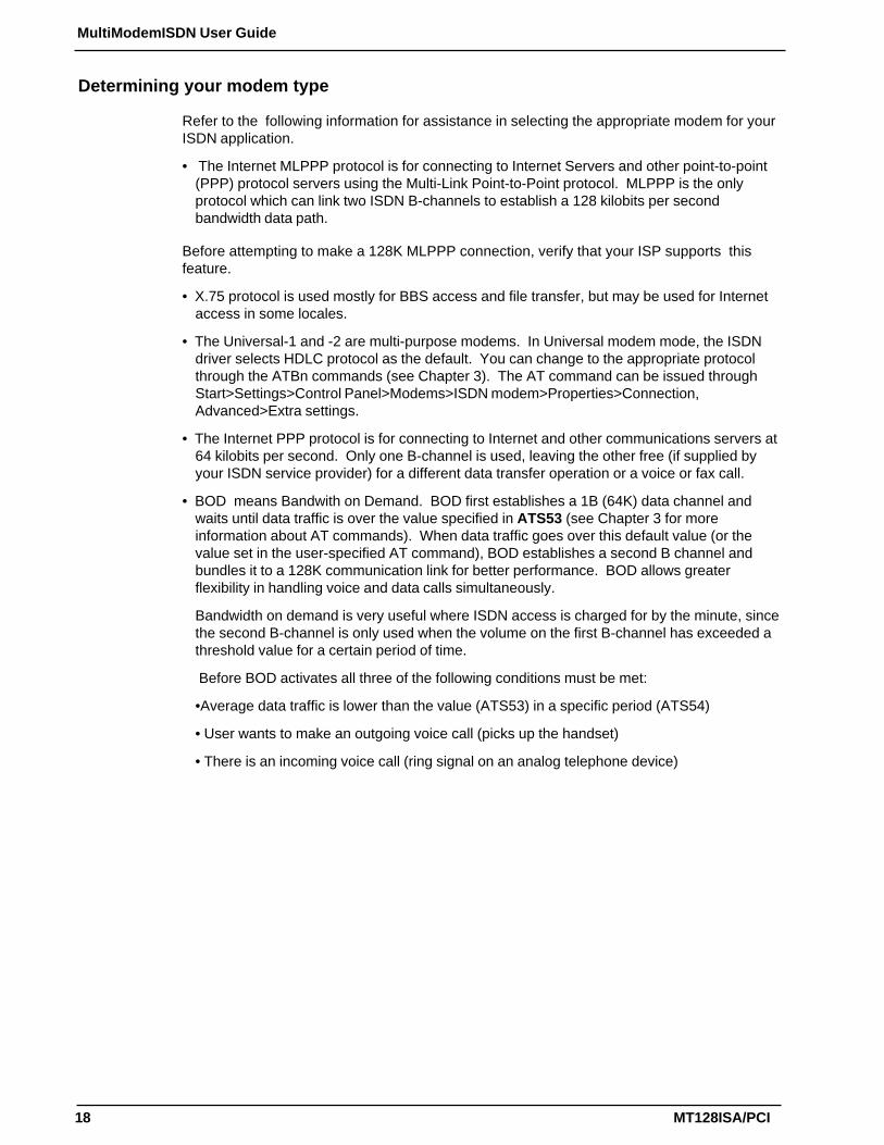
Refer to the following information for assistance in selecting the appropriate modem for yourISDN application.
• The Internet MLPPP protocol is for connecting to Internet Servers and other point-to-point(PPP) protocol servers using the Multi-Link Point-to-Point protocol. MLPPP is the onlyprotocol which can link two ISDN B-channels to establish a 128 kilobits per secondbandwidth data path.
Before attempting to make a 128K MLPPP connection, verify that your ISP supports thisfeature.
• X.75 protocol is used mostly for BBS access and file transfer, but may be used for Internetaccess in some locales.
• The Universal-1 and -2 are multi-purpose modems. In Universal modem mode, the ISDNdriver selects HDLC protocol as the default. You can change to the appropriate protocolthrough the ATBn commands (see Chapter 3). The AT command can be issued throughStart>Settings>Control Panel>Modems>ISDN modem>Properties>Connection,Advanced>Extra settings.
• The Internet PPP protocol is for connecting to Internet and other communications servers at64 kilobits per second. Only one B-channel is used, leaving the other free (if supplied byyour ISDN service provider) for a different data transfer operation or a voice or fax call.
• BOD means Bandwith on Demand. BOD first establishes a 1B (64K) data channel andwaits until data traffic is over the value specified in ATS53 (see Chapter 3 for moreinformation about AT commands). When data traffic goes over this default value (or thevalue set in the user-specified AT command), BOD establishes a second B channel andbundles it to a 128K communication link for better performance. BOD allows greaterflexibility in handling voice and data calls simultaneously.
Bandwidth on demand is very useful where ISDN access is charged for by the minute, sincethe second B-channel is only used when the volume on the first B-channel has exceeded athreshold value for a certain period of time.
Before BOD activates all three of the following conditions must be met:
•Average data traffic is lower than the value (ATS53) in a specific period (ATS54)
• User wants to make an outgoing voice call (picks up the handset)
• There is an incoming voice call (ring signal on an analog telephone device)

19
Chapter 2 - Installation
MT128ISA/PCI
Configuring for Your ISDN Switch
Regardless of the operating system or application you are using, the installation process willrequest information from you about the ISDN switch and your remote connection. Use thefollowing information as a reference while configuring your software.
ISDN Switch Type If you are not sure which switch type you are using, check with your ISDN provider.
CodecTelephone companies use Codecs to convert signals transmitted over their networks.Telephone service providers that adhere to U.S. telecommunications standards use u-law.Many European and Asian telephone companies adhere to A-Law. Check with your ISDNprovider if you are unsure which value to select.
Standby TimeStandby time is a timer which buffers any keypad’s input from an analog device beforesending a message out. In general, this value will not need to be changed from the defaultvalue.
SPIDCertain U.S. ISDN switch types require SPID (Service Profile ID) information be configured inyour software. If required, your telephone company will provide the necessary SPID values.SPID1 refers to the first ISDN line. SPID2 refers to the second ISDN line.
MSN (POTS)MSN (Multiple Subscriber Number) is a supplementary service generally used by EuropeanISDN switches. MSN service provides the possibility of assigning multiple ISDN numbers toa single interface. The POTS field is used to enter the phone number associated with avoice line. In a two channel ISDN configuration, if the MSN (POTS) field is left blank, eithernumber can ring. If a phone number is entered, the number dialed on the incoming call mustmatch the MSN (POTS) value for the analog device connected to the POTS (voice) (a/b) portto be enabled.
SADSAD (Sub addressing) is used by certain European ISDN providers. If subaddresses areavailable in your area enter the phone number in the format, 7706043*1, where 7706043 isthe called (remote) phone number and 1 is the subaddress. The phone number andsubaddress are separated by *.
ProtocolIn some configurations, you will need to select HDLC, X.75 Transparent, V.120 or Auto-Detection as your incoming protocol. The incoming protocol selection is based upon theprotocol of your ISDN adapter. The outgoing protocol selection is based upon the protocol ofthe remote ISDN device to which you are connecting.

20
MultiModemISDN User Guide
MT128ISA/PCI
Windows 3.1 Installation and ConfigurationYou can configure your ISDN connection via COM port emulation, standard WinISDNinterface, or the standard CAPI 2.0 interface in Windows 3.1.
Follow these steps:
1. Insert the ISDN installation CD/diskette into the disk drive.
2. Select the File menu from the Program Manager, then choose Run to execute theSETUP.EXE file from the diskette. The installation software will automatically processthe necessary setup steps.
3. Setup automatically displays the ISDN Configuration dialog box (see figure 2-5).Complete the necessary information in the text boxes of ISDN Configuration dialog box.See Chapter 2 “Before You Begin” for more information about configuring your ISDNswitch type.
Figure 2-5. ISDN Configuration Display
4. When the ISDN adapter installation is complete, restart Windows. The ISDN driver willautomatically load after re-starting Windows 3.1. The ISDN Group Folder appears asshown below.
Figure 2-6. ISDN Group Folder
The ISDN LOG application is used to record the handshaking and data transfer processduring communication. It can be used for debugging purposes so it is useful to have the logrunning while first starting to use your ISDN adapter. Refer to Chapter 4 for more information.

21
Chapter 2 - Installation
MT128ISA/PCI
5. You can re-configure the parameters of step 3 by executing the ISDN Configurer in theISDN Group Folder. The Configuration dialog box also displays the I/O address and IRQvalue in the message bar.
Windows 3.1 Application Interface Setup
Under Windows 3.x applications, you can configure your terminal adapter device using eitherCOM port emulation, the standard WinISDN interface, or the CAPI 2.0 interface.
1. COM Port Emulation. The ISDN driver provides the AT command set interpreter toemulate modems and transfer/receive data through the ISDN network. You must set upyour application software to the appropriate COM ports (COM3 or COM4) tocommunicate with the ISDN adapter. The AT Console program can redirect the ATcommands and data through COM3 or COM4 to the ISDN driver for processing.
• If you want to set up an Internet connection through COM port emulation, TRUMPET is apopular Internet shareware application which includes the TCP/IP and PPP protocols withthe Winsock interface. Many Windows 3.1 Internet modems use TRUMPET to connect tothe Internet and run applications such as Netscape Navigator. TRUMPET users shouldmodify the Network Configuration and Script files to access the Internet through terminaladapters. See Appendix C for an example of a setup modification for TRUMPET.
• When entering Windows 3.1, you must run the AT Console to enable the COM portemulation capability.
• Multilink PPP is not supported at the AT Console. You may make a Multilink PPPconnection through applications which include a TCP/IP and Multilink PPP stack withWinISDN or the CAPI interface.
2. WinISDN Interface. The ISDN driver can transmit/receive data with applications throughthe standard WinISDN interface. The following TCP/IP stacks support the WinISDNinterface.
• NetManage’s Chameleon
• FTP’s Explore
• Frontier’s SuperHighway Access
Refer to the proper TCP/IP stack document respective to your setup dial-up environment forWAN and LAN. We recommend NetManage’s Internet Chameleon (version 4.5 or later) forcompatibility using both PPP and Multilink PPP.
3. CAPI Interface. Applications can also access the ISDN card for up to 128K datatransmission through the standard CAPI 2.0 (or later) interface.
Windows 3.1 Removal of the ISDN Drivers
To remove the ISDN driver from Windows 3.1, click the unInstallSHIELD icon in the ISDNGroup Folder (see figure 2-6).

22
MultiModemISDN User Guide
MT128ISA/PCI
Windows 95 Installation and ConfigurationRead the following Windows 95 installation steps and setup procedures for NDISWAN,virtual modems (VCOMM) and the standard CAPI interface.
After you have installed the internal PC terminal adapter, switch the computer power on andallow Windows 95 to start up. The system should auto-detect a new PnP card and requestdriver installation. Insert the ISDN driver diskette/CD into the appropriate disk drive. Followthe instructions to allow Windows 95 to automatically select the ISDN100.INF file andprocess the necessary installation steps. Restart the computer when prompted.
Figure 2-7. The Windows 95 Update Device Driver Wizard
1. To configure the ISDN Switch type, MSN and SPID values for Windows 95, double ClickStart>Settings>Control Panel>System>Device Manager>ISDNLink>ISDN MT128Adapter>Properties. Select the Setting tab.
Figure 2-8. ISDN Adapter Properties
2. After configuring the switch type, click OK and reboot the computer.

23
Chapter 2 - Installation
MT128ISA/PCI
If Microsoft’s Dial-Up Networking (DUN) is not installed, you’ll need to install(MSDUN13.EXE) or the Microsoft Accelerator Pack. This installation is not required forsystems running Windows 98, NT or Windows 2000.
MSDUN13.EXE can be downloaded from www.microsoft.com. If you have already installedDUN skip to the next section to continue your installation.
1. Select Start>Run and enter MSDUN13.EXE. Follow the installation procedures. Rebootyour PC to enable the program.
Windows 95 and the NDISWAN interface
To connect through the NDISWAN adapter with Windows 95, you must have MicrosoftMicrosoft DUN (Dial-up Networking) or the Microsoft Accelerator Pack installed.
1. Add NDISWAN support by double clicking Start>Settings>ControlPanel>Network>Add>Adapter>Add>Have Disk. Locate the IINWAN95.INF file (thisfile is located on the root of the installation diskette). Click OK to continue with the install.
2. Windows 95 will install the IINWAN95-ISDN adapter and bind the NDISWAN protocol tothe adapter. When the installation is complete, click OK. The installation willautomatically continue with the ISDN Configuration screens.
Figure 2-9. NDISWAN Adapter Installation

24
MultiModemISDN User Guide
MT128ISA/PCI
Figure 2-10. Defining the Switch Protocol
3. Select the Switch protocol that your telephone company uses. For most applications, theAutomatic option will work. Click Next to continue.
Figure 2-11. Configuring Phone numbers and SPIDs
4. Depending upon on your switch type, you will be prompted to enter phone numbers foryour ISDN lines and the corresponding SPIDS (Service Profile ID) or MSN and SADinformation (see Chapter 2 “Before You Begin” for more information).
5. Click Next>Finish to complete the installation. Reboot the system as prompted.
Windows 95 Single Channel Access (NDISWAN)
Next, you’ll need to create a Dial-Up Networking profile for this connection.
1. Select Start>Programs>Accessories>Dial-Up Networking.
2. At the Welcome to Dial-Up Networking screen, click Next. Enter a descriptive name forthis connection. Select an NDISWAN device from the list box (see Chapter 2, “BeforeYou Begin” for more information on these devices). If you need to modify yourconnection preferences, click on Configure and make the necessary changes.
3. Enter the area code and phone number of your ISP or the remote device you will becalling using this connection. Select the appropriate Country code and click onNext>Finish to complete the set up.

25
Chapter 2 - Installation
MT128ISA/PCI
Figure 2-12. Setting up a new NDISWAN Dial-Up Connection
The new dial-up connection is ready to configure.
4. From the Dial-Up Networking folder, right click on your new (NDISWAN in this example)connection icon. Choose Properties.
Figure 2-13. Dial-Up Networking properties
5. On the General tab (see figure 2-13), enter the phone number for the adapter port. Youmay change the connection options by clicking Configure.
6. Click on the Server Types tab to configure logon options, encryption, log file informationand network protocol options including TCP/IP settings for your remote server and DNSconnections. If necessary, contact your ISP or network administrator to obtain thecorrect TCP/IP addressing information.
7. Use the Scripting tab to define scripts that will run when the connection is made.
Click OK to complete the configuration.
To use this new connection, double click on the new Dial-Up Networking connection icon.Enter the user name and password for your remote account and click Connect.

26
MultiModemISDN User Guide
MT128ISA/PCI
Windows 95 Multilinked Channel Access (NDISWAN)
1. To begin, you’ll need to create a new Dial-Up Connection as described in the NDISWANSingle Channel Access section or modify an existing connection. Right click on the Dial-Up connection icon and select Properties.
2. Click on the Multilinking tab. Select Use Additional Devices and then Add. From thelist box, select the second NDISWAN device from the list. When complete, continue toclick OK to leave the Set Additional Link configuration screens.
Figure 2-14. NDISWAN 128 MLP Setup
Your NDISWAN adapter is now ready to make a multilinked connection to your ISP andaccess the Internet. Double click on the Dial-up Networking connection icon just created.
Enter your user-specific information and click Connect. Your adapter will connect inseconds with both channels enabled.
Windows 95 and the VCOMM (Virtual Modem) Interface
During the installation of the Windows 95 drivers, two virtual ISDN COM ports areautomatically created.
1. Install the Virtual Modem for your ISDN COM in Windows 95 by selectingStart>Settings>Control Panel>Modems>Add. Click on Do not detect my modem, Iwill select it from a list, >Next.
2. Click Have Disk, and select MDMASU.INF from the root of the Windows 95 installationdiskette. Click OK,OK.

27
Chapter 2 - Installation
MT128ISA/PCI
3. Select the VCOMM modem you’d like to use with your application (see Chapter 2 “BeforeYou Begin” for more information about selecting your ISDN modem).
Figure 2-15. Virtual Modem Installation
Note: The screens which follow will differ based on the modem type selected.
4. Click Next, and select the port to use with this modem. Click Next>Finish.
Figure 2-16. Linking the Virtual modem to the COM port
5. The Modems properties screen displays. Click Properties.
Figure 2-17. Modem Properties General tab options
The Modem Properties General tab allows you to set the port and maximum speed values.

28
MultiModemISDN User Guide
MT128ISA/PCI
Figure 2-18. Modem Properties Connection tab
6. The default settings on the Connections tab are generally adequate. Click theConnections tab if you need to change FIFO buffers, connection or call preferences. Clickon the Advanced button to make changes to your error control, flow control, add extrasettings or set up a log file. Click OK and Close to finish the configuration.
Windows 95 Single Channel Access (VCOMM)
Before beginning this installation use Start>Settings>Control Panel>Modems to verify theVCOMM modem you plan to use has been installed. In this example, the ISDN (InternetPPP, 64K) Adapter virtual modem is used.
1. You can make a new connection by selecting Start>Programs>Accessories>Dial-UpNetworking>Make New Connection. Name this new connection and select a device.Click Next to continue. Complete the area code and phone number fields for yourconnection. Click Next>Finish.
2. From the Properties screen, select the Configure tab for this ISDN (Internet PPP, 64K)Adapter modem. Verify the modem is associated with an available ISDN COM Port.
You may change or check the parameter settings of Dial-Up Networking by usingStart>Programs>Accessories>Dial-Up Networking; choose the connection icon, then clickthe right mouse button and choose Properties. Enter the Dial-up ISDN phone number underthe General tab. Use the Server Types tab to identify the correct Server type for your remoteconnection and to configure the TCP/IP values for your remote connection.
Figure 2-19. Choose ISDN Adapter Properties
Your VCOMM adapter is now ready to make a connection. Double click on the VCOMM Dial-up Networking connection icon you just created.
Enter your user-specific information and click Connect. Your adapter will connect inseconds with both channels enabled.

29
Chapter 2 - Installation
MT128ISA/PCI
Windows 95 Multilinked Channel Access (VCOMM)
Before attempting to make a 128K MLP connection, verify that your ISP supports the 128KMultilinking PPP protocol.
In this example, Universal modems will be set up for 128K MLP Internet access.
Verify the Universal modems have been set up on your system by clickingStart>Settings>Control Panel>Modems.
1. If the modems are not installed, from the desktop, click on Start>Settings>ControlPanel>Modems>Add. Check the Don’t detect my modem; I will select it from a list box.Click Next and Have Disk. Insert the installation diskette in the appropriate drive andallow the system to install the MDMASU.INF file.
2. Click Next to select the ISDN-Universal-1 (64K) Adapter from the list box and click Next.
3. Select the ISDN COM Port (in this example, COM5) and Click Next>Finish. The systemwill install the modem.
Figure 2-20. Selecting a COM port
4. When the Modem Properties screen appears, the ISDN-Universal-1 Adapter is listed.Click on Add to install the second adapter.
5. Repeat installation steps 1-3 in this section to associate ISDN Universal-2 Adapter to theISDN ComPort2 (Com6). Click Finish>Close to complete the installation.
You are ready to set up multilinking.
1. From the desktop, select Start> Programs>Accessories>Dial-up Networking.
2. Double click on Make New Connection.
3. Provide a descriptive name for this new connection and select the ISDN Universal-1Adapter. Use the Configure button to make changes to the port association, connectionspeed, preferences call preferences, call connection options and modem status. ClickOK and Next when complete.
4. Enter the phone number this connection will dial. Click Next>Finish to complete the newDial-up networking connection.
5. To enable multilinking for this connection from the Dial-up Networking folder, right click onthe icon for this new connection and select Properties.

30
MultiModemISDN User Guide
MT128ISA/PCI
6. Select the Multilink tab and click on Use Additional Devices, then Add. From the listbox, select the ISDN-Universal-2 Adapter as in figure 2-21. Click OK, OK to completethe link.
Figure 2-21. Setting up multilinking
Test your new connection by double clicking on your 128K Dial-Up Connection icon.
The Connect To dialog box is displayed. On the screen, enter your User name andpassword, and click on Connect. The system dials and connects on the first channel andthen dials and connects the second channel.
Windows 95 and the CAPI Interface
To use functions based on the standard CAPI API (see Appendix B), you must install anapplication such as RVS-COM Lite. Refer to Appendix C of this manual for RVS-COM Liteinstallation instructions.
After installing RVS-COM, several new virtual modems become available to configure. Thefollowing example uses the RVS ISDN V.120 modem. Before beginning, ensure the RVS-COM Comm Center is running (the icon will appear on the Windows 95 Task Bar).
CAPI Single Channel Access: Windows 95
1. Make a new Dial-Up Connection by clicking Start>Programs>Accessories>Dial-UpNetworking. Double-click Make New Connection and enter a descriptive name for thisnew connection. In the Select a Device field select the RVS ISDN V.120 modem andclick Configure. Select an available RVS ISDN COM port for this connection and clickOK, then Next.
2. Enter the phone number for the remote connection and click Next>Finish.
3. Right click on the new CAPI (RVS COM) Dial-Up Connection and select Properties. Onthe Server Types tab, select the correct server type for your remote connection. If yourremote server does not use DHCP, enter the correct server and DNS TCP/IP addressinformation.
4. Click OK to complete the configuration.
Test your connection by clicking on the Single Channel (64K) CAPI connection just created.

31
Chapter 2 - Installation
MT128ISA/PCI
Windows 95 Multilinked Channel Access (CAPI)
If you would like to use multilinking with your CAPI connection, first ensure your ISDNprovider supports a 128K MLP option.
The ports you link must first be enabled through RVS-COM. In this example, the RVS ISDNV.120 modems are used.
1. To enable the ports in RVS-COM, open the RVS-COM Comm Center.
2. Click the Services tab. In the Virtual COM Ports section of the window, place a checkmark in front of both ports. Associate each port with a unique COM port number (the twodevices must use different COM ports.) Click Apply, then OK.
Next you will need to verify the two modems to be linked are installed.
3. Either click on the Overview tab or Use Start>Settings>Control Panel>Modems. In thisexample, if two RVS ISDN V.120 modems do not exist, you will need to create a newdefinition for each of them.
4. To create a new definition, go to Start>Settings>Control Panel>Modems>Add. SelectDo Not Detect my modem. I will select it from a list >Next.
5. Click on the Manufacturer RVS Datentechnik. The RVS COM adapters will appear in theModel column. Select RVS ISDN V.120 from the list and click Next.
6. Associate the device with the COM port enabled through RVS-COM in step 2 above.Click Next>Finish.
If you need to add a second RVS modem, repeat the process, associating the secondmodem with the second COM port defined in RVS-COM.
Now you are ready to set up the Dial-Up Networking for this 128K MLP connection.
1. Make a new connection Dial-Up Connection by clickingStart>Programs>Accessories>Dial-Up Networking. Double-click Make NewConnection and enter a descriptive name for this new connection. In the Select aDevice field, select the RVS ISDN V.120 modem and click Next. Use the Configure tabif you need to adjust Port associations or connection preferences. Click Next to enterthe Area Code, Phone number and Country Codes. Click Next>Finish when complete.
2. In the Dial-Up Networking window, right click on the icon for this new connection. Clickon the Multilink tab. Select the Use additional device radio button. Click Add to selectthe RVS ISDN #2 modem. If the phone number for this second connection/channel is notdisplayed, enter it here and click OK.
3. Click the Server Types tab. Select the correct Dial-Up Server type. Click the TCP/IPSettings button to verify the TCP/IP settings for your ISP. If required, enter the remoteserver and DNS IP addresses. Click OK, OK, to close the window.
You are now ready to make a connection through a 128K CAPI interface.
1. Double-click the icon for the Dial-Up Networking connection you just created.
2. At the prompts, enter the user name and password for your remote account and clickConnect. The MultiModem ISDN terminal adapter makes the first, and then the secondconnection in seconds.
32
MultiModemISDN User Guide
MT128ISA/PCI
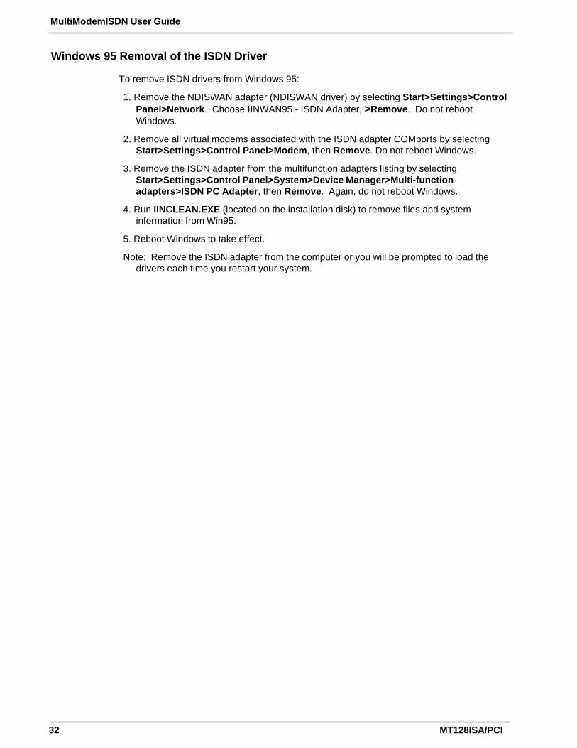
Windows 95 Removal of the ISDN Driver
To remove ISDN drivers from Windows 95:
1. Remove the NDISWAN adapter (NDISWAN driver) by selecting Start>Settings>ControlPanel>Network. Choose IINWAN95 - ISDN Adapter, >Remove. Do not rebootWindows.
2. Remove all virtual modems associated with the ISDN adapter COMports by selectingStart>Settings>Control Panel>Modem, then Remove. Do not reboot Windows.
3. Remove the ISDN adapter from the multifunction adapters listing by selectingStart>Settings>Control Panel>System>Device Manager>Multi-functionadapters>ISDN PC Adapter, then Remove. Again, do not reboot Windows.
4. Run IINCLEAN.EXE (located on the installation disk) to remove files and systeminformation from Win95.
5. Reboot Windows to take effect.
Note: Remove the ISDN adapter from the computer or you will be prompted to load thedrivers each time you restart your system.

33
Chapter 2 - Installation
MT128ISA/PCI
Windows 98 Installation and ConfigurationRead the following installation steps to assist you in the setup and configuration of theNDISWAN, virtual modem (VCOMM) and CAPI interfaces.
1. After installing the internal PC terminal adapter, switch the computer power on and allowWindows 98 to start up. When the system starts it should auto-detect a new Plug-and-Play card and request driver installation. Insert the Windows 98 ISDN driver diskette intothe appropriate disk drive. When prompted, select the ISDNND98.INF file from theinstallation diskette. If the MultiModem ISDN terminal adapter has been installedpreviously, the proper driver is ISDN98.INF. With either driver, Windows 98automatically processes the necessary installation steps. Click Finish to complete theinstallation.
2. After Windows 98 installs the driver, the ISDN Configuration Wizard automatically starts.For most installations, the Automatic setting can be selected as the Switch protocol. Ifyou have connection problems, you will want to return to this screen and specify theactual ISDN switch type as provided by your ISDN service provider. Enter your phonenumbers, SPIDs, MSNs and SADs as required in the fields provided (see Chapter 2“Before You Begin” for more information about these values. Click Next>Finish, andrestart the system when prompted.
You may return to the ISDN Switch configuration if you need to verify or edit the informationby clicking Start>Settings>Control Panel>System>Device Manager. Expand theISDNLink section and double-click on the ISDN MT128 Adapter. Click on the Settings tab toconfigure your Switch Type and phone line options.
Figure 2-22. ISDN Adapter Properties
If the MultiModem ISDN terminal adapter driver is installed by Windows 98, but the terminaladapter does not function after the computer is rebooted, or error message dialogue boxesappear, follow the instructions at the end of this section entitled “Windows 98 Removal ofISDN Driver” . Repeat the installation procedure one more time before contacting technicalsupport.

34
MultiModemISDN User Guide
MT128ISA/PCI
Windows 98 Single Channel Access (NDISWAN)
1. To Add the NDISWAN driver. Click onStart>Settings>Control Panel>Network>Add>Adapter>Add>Have Disk. Specify thefolder for the ISDNND98.INF file (located in the root directory of the Windows 98 ISDNdriver diskette), click OK.
2. Windows 98 lists the IINWAN95-ISDN adapter. Click OK and Windows 98 installs theIINWAN95-ISDN adapter and binds the NDISWAN protocol to the adapter.
Figure 2-23. Selecting the NDISWAN Adapter
3.Click OK. The Windows 98 .CAB (cabinet) files are required to complete the adapterinstallation. You will be prompted to insert the original Windows 98 CD-ROM, or directWindows 98 to the directory in which the .CAB files were copied after Windows 98 wasinstalled. Reboot the computer when prompted.
Next, you’ll need to configure Dial-Up Networking for your NDISWAN connection to theInternet or a remote LAN.
1. Create a new Dial-Up Networking connection by selectingStart>Programs>Accessories>Communications>Dial-Up Networking. Double click onMake New Connection. Provide a name for the connection and select the first deviceIINWAN95 (MT ISDN-Line01) in the Select Device field as shown in figure 2-24. Click Next.

35
Chapter 2 - Installation
MT128ISA/PCI
Figure 2-24. Make a New Connection
2. Enter the area code and phone number for the ISP or remote LAN to which you wish toconnect. Click Next>Finish. The new connection icon (NDISWAN) is added to theDial-Up Networking folder.
Windows 98 Multilinked Channel Access (NDISWAN)
Before setting up a 128K Multi-Link Point-to-Point protocol (MLPPP) connection, check withyour ISP to verify that they support this feature.
1. Select the Dial-up connection you’d like to use for your 128K MLP connection. In thiscase, the NDISWAN Single Channel Access connection defined in the previous section isused as an example.
2. Right click on the NDISWAN Dial-Up Connection and select Properties. In the ConnectUsing field, select the first IINWAN95 device (MT ISDN-Line 01 in this example.).
3. Click the Multi-Link tab, then the Use Additional Devices radio button. Click Add andselect the second IINWAN95 device (MT ISDN-Line 02) from the list box. If the area codeand phone number for this phone line do not display, enter it now. When complete, click OK.
4. Next, click on the Server Types tab and ensure the Server Type and protocol have beenselected for your ISP or remote LAN. Click on the TCP/IP button to enter the IP addressesfor the remote server and DNS machines if required. Contact your ISP or your NetworkAdministrator for assistance in setting these values if you are not sure what to enter on thisscreen. Click OK to close the window.
You are now ready to connect to your ISP and access the Internet through the NDISWANadapter. Double-click on the NDISWAN Dial-Up Networking connection icon just created.Input your user name and password for your Internet Service Provider (ISP) account andclick Connect. The MultiModem ISDN terminal adapter connects in seconds.

36
MultiModemISDN User Guide
MT128ISA/PCI
Windows 98 and the VCOMM (Virtual Modem) Interface
While installing the MultiModem ISDN drivers for Windows 98, two virtual ISDN COM portsare automatically created. You can create a virtual modem definition and attach it to either orboth of these virtual communication ports.
1.To create a new virtual modem definition, click the Start>Settings>ControlPanel>Modems>Add. Select Do not detect my modem, I will select it from a list. ClickNext .
2. Click the Have Disk button, and select the MDMASU.INF file from the driver installationdisk. Choose the appropriate virtual modem type from the Models text box as shown inthe example below (see Chapter 2 “Before You Begin” for more information on selectinga Modem Type for your ISDN application).
Figure 2-25. Selecting the new modem model
3.Click Next, and associate the virtual modem chosen to an available ISDN COM Port.Each modem type will automatically issue the appropriate protocol command to the ISDNdriver when you select it to make a connection. Click Next>Finish, then Close whencomplete.
Windows 98 Single Channel Access (VCOMM)
Before beginning this step, verify an appropriate VCOMM adapter has been installed. In thisexample the ISDN Internet PPP, 64K Adapter is used. If the ISDN (Internet PPP, 64K)Adapter is not listed, create a new virtual modem definition for the device.
1. To create a new definition, go to Start>Settings>Control Panel>Add. Select Do NotDetect my modem. I will select it from a list >Next.
2. Click on Have Disk and browse to the location of the ISDN drivers supplied with yourterminal adapter. From the Models list, select the ISDN (Internet PPP, 64K) Adapter.Select a COMport to associate with this modem. Click Next>Finish.
Once the ISDN (Internet PPP, 64K) Adapter is available, you are ready to create a new dial-up connection.

37
Chapter 2 - Installation
MT128ISA/PCI
1. Make a new connection by clickingStart>Programs>Accessories>Communications>Dial-Up Networking. Double-clickMake New Connection and enter a descriptive name for this new connection. Selectthe ISDN (Internet PPP, 64K) Adapter modem and click Configure. Verify the modemconnection is to ISDN ComPort1 or ISDN ComPort2. If not, change the port setting.
2. Click Next and enter the ISP or remote LAN telephone number to which you wish toconnect. Click Next, then Finish. A new connection icon appears in the Dial-UpNetworking window.
3. Right click on the new VCOMM 64K Access Dial-Up Networking connection and selectProperties. Click the Server Types tab. Ensure the correct settings for your ISP ServerType and protocol have been selected. Click the TCP/IP Settings tab to specify Serverand DNS IP addresses if necessary (Contact your ISP or Network Administrator forinformation about specific values to be entered within these fields).
4. Click OK to close the Dial-Up Networking properties window. You are now ready to makea connection to your ISP and access the Internet through the Virtual Modem interface.
Double-click the icon for the Dial-Up Networking connection just created. Enter your username and password for your Internet Service Provider (ISP) account and click Connect.The MultiModem ISDN terminal adapter connects in seconds.
Windows 98 Multilinked Channel Access (VCOMM)
Before attempting to make a 128K ML-PPP connection, first confirm that your ISP supportsthis function.
This example uses Universal-1 and Universal-2 virtual modems for the128K MLP connection.
Verify the ISDN Universal-1 and ISDN Universal-2 adapters are installed usingStart>Settings>Control Panel>Modems. If the Universal adapters are not listed, you willneed to create a new definition for them.
1. To create a new definition, go to Start>Settings>Control Panel>Modem>Add. SelectDo Not Detect my modem. I will select it from a list >Next.
2. Click on Have Disk and browse to the location of the ISDN drivers supplied with yourterminal adapter. From the Models list, select the Universal-1 Adapter and associate itwith ISDN ComPort1. Click Next>Finish. Repeat the process to add Universal-2Adapter and associate it with ISDN ComPort2. When complete, close the Modem dialogbox.
Once the Universal-1 and Universal-2 Adapters are available, you are ready to create a newDial-Up Connection for this connection.
1. Use Start>Programs>Accessories>Communications>Dial-Up Networking. Doubleclick Make New Connection. In the Select Device field, select the Universal-1 Modemand associate it to the first ISDN COM port.
Next you will need to add an AT command to enable the Async to Sync PPP in ML PPPmode.
2. Right click on the new dial-up connection icon and select Properties On the Generaltab, click on Configure. Next, click on the Connection tab and select Advanced. In theExtra Settings box, type the command ATB41. Click OK, OK, OK to return to the Dial-Up Networking tab. This AT command must be added for both adapters.
3. If prompted, enter the area code and telephone number for your ISP.

38
MultiModemISDN User Guide
MT128ISA/PCI
4. Click Next, then Finish. A new connection icon appears in the Dial-Up Networkingwindow.
Now you are ready to set up multilinking.
1.Highlight the 128K MLP Dial-Up Networking connection icon you just created and rightclick. Select Properties>General Verify that the Primary Device is set to the Universal-1 virtual modem configured for the first ISDN COM port.
2.Click the Multilink tab, and then click the Use additional device radio button. Click Addto select the second Universal-2 Modem. If the phone number for this secondconnection/channel is not displayed, enter it here and click OK.
3. Reopen the 128K MLP Dial-Up Connections Properties window and click the ServerTypes tab. Select PPP: Internet, Windows NT Server, Windows 98 as the type of Dial-Up Server. Click the TCP/IP Settings button to verify the TCP/IP settings for your ISP.If required, enter the remote server and DNS IP addresses.
You are now ready to make a connection to your ISP and access the Internet through a 128KVirtual Modem interface.
1. Double-click the icon for the Dial-Up Networking connection you just created.
2. At the prompts, enter the user name and password for your ISP account and clickConnect. The MultiModem ISDN terminal adapter makes the first, and then the secondconnection in seconds.
Windows 98 and the CAPI Interface
To use functions based on the CAPI API (see Appendix B), you must install an applicationsuch as RVS-COM Lite. Refer to Appendix C of this manual for RVS-COM Lite installationinstructions.
After installing RVS-COM, several new virtual modems become available to configure. Thefollowing example uses the RVS ISDN V.120 modem. Before beginning, ensure the RVS-COM Comm Center is running (the icon will appear on the Windows 98 Task Bar).
Windows 98 Single Channel Access (CAPI)
1. Make a new Dial-Up Connection by clickingStart>Programs>Accessories>Communications>Dial-Up Networking. Double-clickMake New Connection and enter a descriptive name for this connection. In the Select aDevice field, select the CAPI compliant (RVS ISDN) modem you’d like to use. In thisexample, the RVS ISDN V.120 modem is selected. Click Next and enter the Phonenumber to be dialed for your remote connection. Click Finish.
2. Right click on the new CAPI Dial-Up connection and select Properties. On the ServerTypes tab, select the correct server type for the remote device you are connecting towith. If your remote server does not use DHCP, enter the correct server and DNS TCP/IP address information.
3. Click OK to complete the configuration.
You are now ready to make a remote connection through the CAPI single channelconnection just created.
1. Double-click the icon for the Dial-Up Networking connection for your CAPI connection.
2. At the prompts, enter the user name and password for your remote account and clickConnect. The MultiModem ISDN terminal adapter makes the first, and then the secondconnection in seconds.

39
Chapter 2 - Installation
MT128ISA/PCI
Windows 98 Multilinked Channel Access (CAPI)
If you would like to use multilinking with your CAPI connection, first ensure your ISDNprovider supports this option.
The ports you link must first be enabled through RVS-COM. In this example, RVS ISDNV.120 modems are used.
1. For RVS-COM to recognize the second channel, it must first be enabled in RVS-COM.To do this, open the RVS-COM Comm Center.
2. Click the Services tab. In the Virtual COM Ports section of the window, place a checkmark in front of both ports. Associate each port with a unique COM port number (the twodevices must use different COM ports.) Click Apply, then OK.
Next you will need to verify the two modems you’d like to link are installed.
3. Use Start>Settings>Control Panel>Modems. In this example, if two RVS ISDN V.120modems do not exist, you will need to create a new definition for each of them.
4. To create a new definition, go to Start>Settings>Control Panel>Add. Select Do NotDetect my modem. I will select it from a list >Next.
5. Click on the Manufacturer RVS Datentechnik. The RVS COM adapters will appear in theModel column. Select RVS ISDN V.120 from the list and associate it with the COM portenabled through RVS-COM in step 2 above. Click Next>Finish. If you need to add asecond RVS modem, repeat the process, associating the second modem with thesecond COM port defined within RVS-COM.
Now you are ready to set up Dial-Up Networking for this 128K MLP connection.
1. Make a new Dial-Up Connection by clicking:Start>Programs>Accessories>Communications>Dial-Up Networking. Double-clickMake New Connection and enter a descriptive name for this connection. In theConnect Using field, select the RVS ISDN V.120 modem and click Next. Enter thephone number for the remote server. Click Next>Finish.
2. Next, right click on the new CAPI connection. Click on the Multilink tab. Click the Useadditional device radio button. Click Add to select the RVS ISDN #2 modem from thelist box. If the phone number for this second connection/channel is not displayed, enter ithere and click OK.
3. Reopen the 128K MLP Dial-Up Connections Properties window and click the ServerTypes tab. Select PPP: Internet, Windows NT Server, Windows 98 as the type of Dial-Up Server. Click the TCP/IP Settings button to enter the TCP/IP settings for the remotedevice. If required, enter the remote server and DNS IP addresses. Click OK, OK, toreturn to the Dial-Up Networking window.
You are now ready to make your remote connection through the 128K CAPI interface.
1. Double-click the icon for the Dial-Up Networking connection just created.
2. Right click on the new CAPI Dial-Up Connection. Select Properties. At the prompts,enter the user name and password for your remote account and click Connect. TheMultiModem ISDN terminal adapter makes the first, and then the second connection inseconds.

40
MultiModemISDN User Guide
MT128ISA/PCI
Windows 98 Removal of the ISDN Drivers
To remove the ISDN drivers from Windows 98:
1. Remove the NDISWAN adapter driver by selecting Start>Settings>ControlPanel>Network. Choose the IINWAN95 - ISDN Adapter. Click Remove. Do not rebootWindows
2. Remove all of the virtual modems associated with ISDN adapter COMports by selectingStart>Settings>Control Panel>Modem. Click Remove. Do not reboot Windows.
3. Next, remove the ISDN multifunction adapter by selecting Start>Settings>ControlPanel>System>Device Manager>Multi-function adapters>ISDN MT128 Adapter(Master Device). Click Remove. Do not reboot Windows. Close Control Panel.
4. Run IINCLEAN.EXE (located on the Windows 98 driver disk) to remove files and systeminformation from Windows 98 placed there by the MT128 Windows 98 driver installation.
5. Reboot Windows for the changes to take effect.

41
Chapter 2 - Installation
MT128ISA/PCI
Windows NT Installation and ConfigurationYour internal ISDN PC adapter under Windows NT can be used with NDISWAN or thestandard CAPI interface.
Note: To install, configure and remove devices under NT, your logon permissions mustinclude the ability to load and remove device drivers.
Once you’ve inserted the ISDN card into the computer and switched on the power for yourcomputer, it should boot into Windows NT. Follow the instructions below to install the ISDNdriver:
1.Click Start>Settings>Control Panel>Network>Adapter> Add
2.Click Have Disk and specify the correct drive for the NT ISDN Installation disk/CD.
3. On the Select OEM Option Screen, select the ISDN MT128ISA Adapter. Click OK.
4.The ISDN Driver Bus Location dialog box appears. Select the proper bus type for yourinstalled adapter. If you are using an ISA adapter, select ISA. If you are using a PCIadapter, select PCI. Set the Bus Number to 0. Click OK.
5.Windows NT copies the ISDN driver into your system and displays the ISDN PC AdapterConfiguration screen as shown in figure 2-26.
If this screen does not appear automatically or if you need to edit your ISDN Switchconfiguration, return to this screen by selecting Start>Settings>Control Panel>Network.Right click and select Properties.
Figure 2-26. ISDN PC Adapter Configuration
6. Use the list box to select the Switch Type. If you are not sure which Switch Type toselect, contact your ISDN provider. If your telephone service provider uses MSN(Multiple Subscriber Numbers) or SAD (Sub-Addressing), enter the information given toyou by your ISDN provider in the appropriate fields. If your ISDN service requiresSPIDs(Service Provider IDs), enter these values in the SPID1 and SPID2 fields. Refer toChapter 2 “Before You Begin” for more information.
If you plan to use PTP Mode (Point to Point Mode) or X.25 select those options here.
7. Click on the NDISWAN Setting tab and enter any necessary phone number information.

42
MultiModemISDN User Guide
MT128ISA/PCI
Note: After installation and any time you make changes to values within the ISDNconfiguration dialog box, you will need to restart Windows NT for the settings to takeeffect.
8. When complete, Click OK to continue.
The RAS Setup Message appears as shown in 2-27. Click OK to continue the installation.
Figure 2-27. Remote Access Service Setup Message
9. Click OK to install and setup RAS.
10. The screen shown in figure 2-28 appears.
Figure 2-28. Adding a RAS device
11. If you do not see ISDN1-IINWANNT listed in the port fields, click Add.
12. From the list box, select ISDN1-IINWANNT and click OK. The first NDISWAN device isadded to the Remote Access Setup Port list.

43
Chapter 2 - Installation
MT128ISA/PCI
13. Add your second NDISWAN ISDN device by clicking Add and selecting ISDN-2-IINWANNT from the list box. Click OK to add this device to the RAS Setup as shown infigure 2-29.
Figure 2-29. Remote Access Services (RAS) Setup
14. Select the ISDN1 and click Configure to setup Port Usage for this ISDN1port.Depending upon your use of this channel, select Dial out only, Receive calls only, or Dialout and Receive calls then click OK.
Figure 2-30. Configure Port Usage Installation
If you choose Dial out only, click OK, and then click the Network tab. Select the protocolyou will use. If you are going to access the Internet, choose TCP/IP.
Figure 2-31. Configure Dial Out Protocol
If you Select Receive calls, or Dial out and Receive calls, click OK, then click the Networktab. The screen displayed in fiigure 2-32 appears. Contact your ISP or network administratorif you require assistance in configuring your TCP/IP settings. Also check that you haveenabled, allow any authentication including clear text, in the Security settings. Click OK.

44
MultiModemISDN User Guide
MT128ISA/PCI
Figure 2-32. Define Network Configuration
15. Select ISDN2 and click Configure to set up the appropriate values for the second line.
16. You have completed your ISDN driver installation and have added two NDISWANadapters. Click Continue>Close. NT will bind the appropriate drivers to your adapterand you will be prompted to restart your computer.
Windows NT Single Channel Access (NDISWAN)
Once your adapter is installed, you are ready to set up an ISDN Dial-Up Networkingconnection for single channel access.
1. Select Start>Programs>Accessories>Dial-Up Networking. If there are no previousentries in your phonebook, a dialog box appears stating The Phonebook is empty. PressOK to add an Entry. The New Phone book entry wizard appears. Enter a name for yournew Phone Book entry. In the Dial Using field, select the IINWANNT NDISWAN adapteryou will use for this connection.
2. Next, enter the primary phone number for your ISP or remote server. If you need tospecify a Country, Region or Area code, click on the Telephony dialing properties boxand fill in your dialing information. If your ISP or remote server has more than one phonenumber that can be dialed, click on Alternate Phone Numbers and add the phonenumbers to the screen.
3. On the Server tab, select the correct remote Server Type. Click on TCP/IP to set upaddresses for your remote server. Click OK to continue.
4. When complete, click OK>Close.
To use this new connection, open the Dial-Up Networking folder and select the NDISWANsingle channel access entry from the phonebook entry drop down list box. Click Dial.
Enter the user name and password for your ISP or remote server account and click OK.Your adapter will connect in seconds.
Windows NT Multilinked Channel Access (NDISWAN)
Before beginning installation of a 128K MLP connection, verify with your ISDN provider offers128K MLP service and that it is enabled on the remote server.
In the following example the single channel access connection created in the previoussection will be modified to support a 128K MLP connection.
1. Open the Network Dial-Up Connection folder and select the NDISWAN Single ChannelAccess connection created in the previous section.

45
Chapter 2 - Installation
MT128ISA/PCI
2. Click the More button and select Edit entry and modem properties.
3. Under the Basic tab, use the Dial Using field list box to select Multiple Lines.
4. Click Configure and place a check mark in the boxes corresponding toIINWANNT(ISDN1) and IINWANNT(ISDN2).
Figure 2-33. Multiple Line Configuration
5. Highlight IINWANNT(ISDN1). Click Phone numbers and enter the phone number for thefirst ISDN line if it is not yet installed. Click Add, then OK.
6. Next, highlight IINWANNT(ISDN2). Click Phone numbers and enter the phone numberfor the second ISDN line. Click Add, then OK. Click OK again to close the screen.
You are ready to make a connection with your ISP or remote server using multilinkedchannels.
To use this new MLP connection, open the Dial-Up Networking folder and select theNDISWAN multiple linked channel entry from the phonebook entry list box. Click Dial.
Enter the user name and password for your ISP or remote server account and click OK.Your adapter will connect in seconds.
After dialing, the Dial-Up Monitor icon appears in the lower right hand corner of your screen.Double click on this icon to view your connection status including connection speed, servertype, etc.
If you have problems with the connection (such as the line being dropped or inability toaccess the Internet or your remote network), review the network settings with your ISP ornetwork administrator. You also may want to test accessing the connection without usingMultilinking.

46
MultiModemISDN User Guide
MT128ISA/PCI
Windows NT and the CAPI Interface
Before using the standard CAPI interface you must install a CAPI compliant application suchas RVS-COM Lite. See Appendix C for installation instructions.
Under NT, The CAPI modems available through RVS-COM must be added as modems andalso made available through RAS (Remote Access Services).
To add a new modem,
1. Select Start>Settings>Control Panel>Modems>>Add
2. Select Don’t detect my modem, I will select it from a list.
3. On the Install New Modem screen, select RVS Datentechnik from the Manufacturers liston the left side of the window. The RVS modems will display in the models column onthe right side of the window. Select the RVS-COM modem you would like to use for yourISDN connection (in this example RVS Fax has been selected). Click Next to continue.
Figure 2-34. Selecting an RVS-COM modem
4. On the screen which follows, select the port you’d like to associate with this modem. ClickNext>Finish to finish adding this first modem.
You may press OK when complete. If you will be using linked channels, Add the secondmodem at this time by repeating the steps above. Associate the second modem with aunique COM port.
5. The screen shown in figure 2-35 appears asking if you would like to configure Dial-UpNetworking. Respond by clicking Yes.
Figure 2-35. Dial-Up Networking dialog box

47
Chapter 2 - Installation
MT128ISA/PCI
6. The Remote Access Setup Screen displays (figure 2-36).
Figure 2-36. Selecting the CAPI (RVS-COM) device in RAS
7. Add the RVS-COM device to Remote Access Services by clicking Add. From the devicelist, highlight the desired modem and click OK.
8. With the newly added device highlighted, click Configure. You will be presented with theConfigure COM Port Usage screen. Select an available ISDN COM port for this deviceand select either Dial-Out only, Receive Calls Only or Dial-Out and Receive calls.Click OK when complete.
If you will be setting up 128K MLP access, you may click Add on the Remote Access Setupscreen and add the second RVS-ISDN device. When the second device has been added,highlight this new device and click Configure to define the COM port usage for this channel.
After adding the devices to RAS for this connection, click Continue. Restart the computer asprompted.
Note: If you add a modem at a later date, it must be added to Windows NT RAS before it canbe used.
To add the modem to RAS:
1. From your NT desktop, right click on Network Properties and select Properties.
2. Click the Services tab.
3. When the RAS Services screen appears, select Add.
4. Select the modem you’d like to use with your application. Next, press Continue.
5. Associate the modem to a unique COM port and save the connection.
When the Network Properties screen closes you will be prompted to restart the computer.
Windows NT Single Channel Access (CAPI)
The RVS-COM installation makes several RVS-COM (CAPI compliant) modems available.Once they are added as modems and set up under RAS, you are ready to set up your Dial-Up connection.
1. Set up the Dial-Up Networking connection by selecting Programs>Accessories>Dial-UpNetworking.
2. Click New. Provide a descriptive name for this connection and enter the phone numberfor your remote server or ISP.

48
MultiModemISDN User Guide
MT128ISA/PCI
3. Next, select the CAPI (RVS-COM) modem and COM port for this connection in the Dial-Using field.
4. When complete, click the Server tab and verify the Dial-Up server type. Click the TCP/IPsettings tab if you need to specify IP addresses for your remote server or DNS. Contactyour ISP or network administrator for information on configuring this screen.
5. Click OK to return to the Network Dial Up folder.
To use this connection, highlight the connection and click Dial. Your ISDN adapter willconnect within seconds.
Windows NT Multilinked Channel Access (CAPI)
Before a second channel can be linked using CAPI, a second port must be defined withinRVS-COM.
1. To make the second port available, open the RVS-COM Comm Center.
2. Click the Services tab. In the Virtual COM Ports section of the window, place a checkmark in front of both ports. Associate each port with a unique COM port number (the twodevices must use different COM ports.) Click Apply, then OK.
If the second CAPI device has not been installed add a second RVS-COM modem and makeit available through RAS as described previously in this section.
You are now ready to create your Dial-Up Networking connection for multilinking. In thisexample, the Single Channel Access connection will be modified to allow for multilinking.
1. Click on Programs>Accessories>Dial-Up Networking.
2. Select the Single Channel CAPI connection and click More. Select Edit entry andModem Properties.
3. In the Dial Using list box, select Multiple Lines.
4. Next, press Configure. Place a check mark in the box associated with the two RVS-ISDN lines you will be linking.
5. Highlight the first line and select Phone Numbers. If not previously entered, enter thephone number for this line. Click Add and OK.
6. Highlight the second line and select Phone Numbers. If not previously entered, enter thephone number for this line. Click Add and OK.
To use this 128K MLP Dial-Up connection, click Programs>Accessories>Dial-UpNetworking. Double click on this newly created CAPI multilink connection. Both phone lineson your MultiModem ISDN adapter will connect in seconds.
Windows NT Removal of the ISDN Drivers
To remove the ISDN Driver in Windows NT, ClickStart>Settings>Control Panel>Network Icon>Adapters. Select the Multi-Tech ISDNDriver. Click Remove.
You will be prompted to reboot your system when you exit the network properties dialog box.You must reboot for the changes to take effect.

49
Chapter 2 - Installation
MT128ISA/PCI
Windows 2000 Installation and ConfigurationFollow these instructions to setup and configure the MultiModem ISDN adapter for Windows2000. The supported application interfaces for Windows 2000 include CAPI 2.0 andNDISWAN. This driver provides for multi-card support in the same PC.
The MT128 driver files for Windows 2000 are located on the Windows 2000 installationdiskette in a self-extracting file. Although the Windows 2000 driver diskette is labeledVersion 2.52, the diskette contains the current Windows 2000 driver which is version 3.40.
1. To extract the files, place the Windows 2000 driver diskette in the A: drive.
2. Use Explorer to view the contents of the diskette in drive A.
3. Double Click on the MT128 self-extracting file icon.
4. The WinZip Self Extractor will display. The default installation folder is c:\MT128. If youwould prefer to extract the files to a different location, you may change the file path orfolder before extracting the files.
5. Click on UnZip to extract the files. The program will extract 12 files and requires 1.42 MBof disk space.
After installing your ISDN card, switch the computer power on and allow Windows 2000 tostart up. When the Windows 2000 system starts it should auto-detect a new Plug-and-Playadapter and request driver installation.
Figure 2-37. Installing the Windows 2000 ISDN drivers
1. Press Next to continue the installation.
Figure 2-38. Locating the driver files

50
MultiModemISDN User Guide
MT128ISA/PCI
2. When the Install Hardware Device Drivers screen displays, press Next. On the screenwhich follows, ensure the correct optional search location is selected for the location ofyour driver files and click Next.
At any time during this installation, if the Digital Signature Not Found screen appears,respond Yes to continue with the installation.
3. The wizard will continue the installation and install ISDNLINK.INF from the foldercontaining the ISDN Windows 2000 device driver.
Figure 2-39. Completing the installation of the ISDN MT128 Adapter
When the installation is complete, reboot the computer.
Configuring NDISWAN for Windows 2000
1. Use the Windows 2000 Device Manager to configure your ISDN adapter. SelectStart>Settings>Control Panel>System>Hardware>Device Manager to display thedevices attached to your computer.
2. Expand the Network adapters section of the Device Manager to display the Multi-TechSystems ISDN_MT128 ISDN device as in figure 2-40.
Figure 2-40. Displaying the ISDN Device information
3. Right click on Multi-Tech Systems ISDN_MT128 ISDN Device and select Properties.
4. From the Multi_Tech Systems ISDN_MT128 ISDN Device Properties screens, select theISDN Tab as shown in figure 2-41.

51
Chapter 2 - Installation
MT128ISA/PCI
Figure 2-41. The Multi-Tech ISDN_MT 128 ISDN Device Properties display
5. Use the list box to select the correct Switch Type or D-Channel protocol. If you are notsure which type you are using, check with your ISDN provider. Press Configure tocontinue with the set up.
The following installation screen sequence will vary depending upon the switch type youselected in the previous step.
If your switch type requires ISDN Phone Number and SPID information, screen similarto figure 2-42 appears.
Figure 2-42. Configuring ISDN Phone Number and SPID Information
a. Highlight the first Channel and enter the Phone number and SPID information provided byyour ISDN service provider. If you have a second ISDN Channel, highlight Channel 2and enter the Phone number and SPID information associated with it. Click OK whenyou have completed the screen.
If the switch type you selected uses MSN (Multiple Subscriber Numbers) or SAD (sub-addressing) you will see a screen similar to 2-43.
Figure 2-43. Configuring Multiple Subscriber Numbers

52
MultiModemISDN User Guide
MT128ISA/PCI
a. Enter the MSN (Multiple Subscriber) and SAD (Sub-addressing) information for eachISDN line. Click OK when you are done.
If your switch type requires ISDN Logical Terminal information, see figure 2-44.
Figure 2-44. ISDN Logical Terminal configuration
a. Complete the Telephone number and sub-addressing information using the informationprovided by your telephone company. Click OK to complete the set up.
Windows 2000 Single Channel Access (NDISWAN)
To use a single channel NDISWAN connection, you must set up a Dial-Up Networkingconnection. To launch the Windows 2000 Network Dial-Up Wizard, selectStart>Settings>Network Dial-up Connections>Make New Connection.
1. At the Welcome To the Network Connections Wizard screen, click Next.
2. Select the type of network connection for this Dial-Up connection as shown in figure 2-45.Click Next to continue.
Figure 2-45. Selecting a Network Connection
Depending upon the type of connection you are making, the sequence of screens thatappear will vary. In this example, a Dial-Up Internet connection through a phone line andmodem are used. During the setup of the Internet connection you will be prompted forinformation about your Internet connection.

53
Chapter 2 - Installation
MT128ISA/PCI
For an Internet Dial-Up connection, the Choose Modem screen will display as in figure 2-46.
Figure 2-46. Choosing a modem
3. Select the ISDN Device -00 from the list box and press Next.
4. Enter the area code and phone number for this device.. Click the Advanced button if youneed to configure your connection type (PPP, SLIP or C-SLIP), or your logon options.Press Next to continue.
5. The Internet Account Logon screen appears. Enter the User Name and Password foryour ISP account and press Next.
6. Enter a name for this connection in the field provided. You will be given an opportunity toconfigure your optional Internet Mail account. When finished setting up your account anddial up connection information, click Next>Finish.
To use this new Dial-Up Connection, click Dial.
Windows 2000 Multilinked Access (NDISWAN)
To use multilinking with your NDISWAN connection, you must set up a Dial-Up Networkingconnection.
In this example, we’ll use the NDISWAN Dial-Up Connection created in the preceedingNDISWAN Single Channel Access procedure.
1. Select Start>Settings>Network Dial Up Connection. Right click on (Your Dial-UpConnection Name). Click Properties.
2. In the Connect Using dialog box, place a check mark in the boxes corresponding to thefirst and second ISDN channels, then click OK.
To use this new Dial-Up Connection, click on Dial.

54
MultiModemISDN User Guide
MT128ISA/PCI
Windows 2000 and the CAPI Interface
Before using the standard CAPI interface with Windows 2000, you must install a CAPIapplication such as RVS-COM. See Appendix C of this manual for RVS-COM installationinstructions.
Next, you’ll need to install the modems you plan to use with your CAPI interface.
1. To add a modem, select Start>Settings>Control Panel>Phone and Modem Options.Select the Modems tab. Next select Add. Choose Don’t detect my modem. I will select itfrom a list. Click Next.
2. In the Manufacturer column, select RVS Datentechnik. In the right hand column, selectthe RVS modem you’d like to use for your ISDN application as shown in figure 2-47.
Figure 2-47. Selecting a CAPI Device
3. Select an available ISDN COM port and press Next.
If a Digital Signature Not Found screen appears, select Yes to continue, then Finish. Youwill be returned to the Phone and Modem Options Modem tab.
If you need to add a second CAPI compliant device to set up a multilinking, click the Addbutton and repeat the process to add the second device.
Once your RVS-COM (CAPI) devices have been added, you are ready to set up a Dial-UpConnection for your CAPI application.
Windows 2000 Single Channel Access (CAPI)
If RVS-COM Comm Center does not appear on the Windows 2000 task bar, launch theprogram using Start>Programs>RVS COM Lite.
1. Create the Dial-Up profile for this connection by clicking Start>Settings>Network andDial-Up Connections>Make New Connection.
2. Click Next to select your network connection type.
3. Continue through the Dial-Up Connection screens as outlined in the NDISWAN SingleChannel Access section of the Windows 2000 section of this manual. When presentedwith the Choose Modems screen (figure 2-47), select the RVS-ISDN modem (or theCAPI modem appropriate for your ISDN CAPI compliant application). Click OK.
55
Chapter 2 - Installation
MT128ISA/PCI
4. You will be prompted to set up the area code and phone number for the remoteconnection. When complete, click Next.
To use this new Dial-Up Connection, click Dial.
Windows 2000 Multilinked Channel Access (CAPI)
If RVS-COM Comm Center does not appear on the Windows 2000 task bar, launch theprogram using Start>Programs>RVS COM Lite.
The CAPI COM ports must be enabled through RVS-COM before setting up the multilinkedCAPI connection. If the RVS-COM modems you plan to link have not been installed do sobefore continuing with this process. (To add the modems, use Start>Settings>ControlPanel> Phone and Modem Options>Add as outlined previously in the Windows 2000installation instructions).
1. To enable the CAPI ports through RVS-COM, open RVS Comm (double click on CommCenter on the Windows 2000 task bar).
2. Click the Services tab. In the Virtual Modem section of the screen, click on the boxesassociated with the two RVS-COM ports you will be linking. Associate each modem witha unique COM port. Click Apply, then OK.
Next, you’ll create a Dial-Up connection definition for this connection by modifying the CAPISingle Channel Access connection created in the previous section.
1. Go to Start>Settings>Network and Dial-Up Connections. Right click on (Your CAPISingle Access Connection Name).
2. Select Properties. On the General tab, place a check mark in the boxes correspondingto the 2 RVS ISDN modems you will be linking. Press OK.
To test the connection, press Dial. Your multilinked CAPI devices will connect withinseconds.
ISDN Monitor, ISDN Line Test Tool and Driver Configuration
To use the ISDN monitor, ISDN line test tool and driver configuration functions, runLINKSTS.EXE. Install this program by selecting Start>Run>LINKSTS.EXE (you mayusethe browse button to locate this file in the Windows 2000 driver folder). Press OK to installthe program. The LINKSTS program icon will appear on the task bar.
Place the cursor over the program icon on the task bar to display the application name, driverversion number and the monitored ISDN card name.
Right click on the program icon to display options for Configuration, Linetest, Log informationand Exit.
1. Right click on the LINKSTS application icon on the task bar. Select Configuration todisplay your current ISDN information

56
MultiModemISDN User Guide
MT128ISA/PCI
Expand the list to display information for your ISDN devices as shown in figure 2-48. APOTS (A/B) port will display for ISDN devices that include this feature (modelsMT128ISA-UV, MT128PCI-SV).
Figure 2-48. ISDN device, NDISWAN and POTS information displays.
2. Highlight ISDNDevice-00 (ISDN-MT128) and click Properties to display the ISDNinformation as shown in the Basic Configuration screen (figure 2-49).
Figure 2-49. ISDN Device Basic Configuration
The information which follows describes the fields used in configuring this device.
Alias Name - Displays the alias name for this ISDN device. You may change this field ifdesired.
ID -This field displays the CAPI application ID as well as error codes for ISDN drivers thatare not properly functioning.
Interface - Displays ISDN device interface information
BUS - Displays the PC bus type (ISA or PCI) for the ISDN device.
Type - Displays information about your adapter type (internal, external, passive or active).
POTS Port - This field displays the number of available POTS (A/B) ports on this device.
Provide Tone -Yes indicates a Tone is provided. No indicates the device does not havea tone.
Resource - Displays the resource information Windows 2000 has assigned to this device.

57
Chapter 2 - Installation
MT128ISA/PCI
SWITCH - Displays the ISDN Switch type you are using.
SPID 1: Displays SPID information for the first ISDN line.
SPID2: - Displays SPID information for the second ISDN line.
PTP Mode - Check the PTP box to enable Point to Point mode. The default for this fieldis blank. If your telephone company specifies a TEI value, enter it in the TEI: field.
X.25 on DChannel - Check this field to enable X.25 on D channel service. Also specifythe TEI value. If X.25 Channel D is not available leave this field blank.
MSN List - Click on MSN List to add Multiple Subscriber Numbers for this device. Leavethis field blank if your ISDN provider does not use MSN services.
3. When you have completed configuration of this screen, click OK to return to the ISDNLinkConfiguration screen (figure 4-48).
You are now ready to configure your NDISWAN ports.
1. From the ISDNLink Configuration screen, expand the NDISWAN Ports section andhighlight ISDNDevice-00. Click on Properties.
2. The ISDN Device-00-Setting screen displays as shown in figure 2-50.
Figure 2-50. Configure MSN, SAD and protocol options.
3. Enter the information provided by your telephone company into the appropriate fields.
4. If you want to use MLPPP (Multi-Link Point to Point Protocol) or MLPPP+BOD(Bandwidth on Demand) for outgoing calls, check Enable Multilink PPP and click theAdvance button to display the screen shown in figure 2-51.
Figure 2-51. Setting up a Multi-Link connection

58
MultiModemISDN User Guide
MT128ISA/PCI
5. If you would like to activate BOD (Bandwidth on Demand), check Enable BOD.
The default value for Data Flow Rate is 1Kbytes/sec. The Inactivity Timeout defaults to 5minutes. This setting is used to establish a second channel when the data flow rate in thefirst channel is over the set value. At a default value of 1Kbyte/second, the second channelis dropped if data flow is lower than 1 Kbyte/second averaged over 5 minutes or if anincoming or outgoing voice call is initiated.
6. To set up Multilinking, click on Add. Select the Additional Link and click OK Theadditional link will display on the screen.
Figure 2-52. Configuring Multilinking
7. Highlight the new link and click Edit. Enter the remote telephone number in the Call outnumber field. If your telephone company provides a Call out subaddress, enter it here.Click OK on each screen to exit channel configuration.
Windows 2000 POTS/Voice Port Configuration
The POTS/Voice feature is available only on models MT128ISA-UV and MT128PCI-SV.
1. On the ISDNLink Configuration screen (figure 2-48), highlight the POTS/Voice port andclick Properties. The screen shown in figure 2-53 displays.
Figure 2-53. ISDN POTS Settings
2. Select the appropriate Codec, Call Type and Dial Standby options for your POTs device.(Refer to Chapter 2 “Before You Begin” for addition information about options available onthis screen).
3. When you have completed the POTS port configuratio, click OK.
Now you are ready to set up the POTS/Voice port.
1. Return to the ISDNLink Configuration screen (figure 2-48 and expand the POTS devicesection.

59
Chapter 2 - Installation
MT128ISA/PCI
2. Highlight POTS port 1 and click Properties to display the screen shown in figure 2-54.
Figure 2-54. Configuring the MSN and SAD options for the POTs port.
3. If your ISDN provider offers MSN or SAD, select a number from the list boxes. If youwould like your incoming calls to match the MSN or SAD number before activating thedevice, click on Enable Filter of the corresponding service. Click on OK to complete theconfiguration.
Windows 2000 Removal of the ISDN Drivers
Remove the ISDN adapter driver by using the following procedure.
1. Click Start>Settings>Control Panel>System> Hardware>Device Manager. Expandthe Network Adapter section to display your computer’s adapters.
2. Highlight the ISDN_MT128 adapter.
3. Right click and select Uninstall.
4. When prompted, click OK to confirm device removal.
5. Reboot the computer

Chapter 3 - AT Commands

61
Chapter 3 - AT Commands/S-Registers
MT128ISA/PCI
AT COMMANDS
Introduction
AT commands are the means by which you and your communications software are able tocommunicate with and configure your ISDN adapter. These commands enable you toestablish, read and modify parameters associated with your ISDN connections, line protocolsand call handling. The following provides a list of the AT commands recognized by Multi-Tech’s MultiModem ISDN terminal adapters.
Where indicated below, the AT prefix must be issued with the command. The AT commandtells the modem “ATtention!, commands to follow”. If you issue AT as a command by itself,the adapter should respond OK, indicating that your cables are connected correctly and yourbaud rate is set properly.
AT commands are entered in HyperTerminal mode or can be issued as an extra setting foryour connection. Use Start>Settings>Control Panel>Modems>ISDNModem>Properties>Connection>Advanced>Extra settings.
Commands and DescriptionsATA Answer an incoming callATBn Select protocol of transmission in B channelATB0 64K HDLC (default with universal modems under Win95)ATB20 V.120 Async.ATB21 V.120 Sync.ATB3 X.75 Transparent, the same as ATB30 (default with ISDN X.75 Transparent modem under Win95)ATB30 X.75 TransparentATB31 X.75 T.70 NLATB32 X.75 ISO 8208ATB4 Async PPP to Sync PPP converter (default setting with Win95 Async to Sync PPP modem)ATB41 Async to Sync PPP conversion in ML PPP mode, compatible with Microsoft ISDN Accelerator packATB42 Async to sync PPP conversion to MLPPPATB43 Async to sync PPP conversion in MLPPP+BOD (bandwidth on demand)ATB6 Async to sync PPP conversion over X.75 transmissionATB61 Async to sync PPP conversion over X.75, but setting up secondary device in Dial-Up Networking required.ATB62 Async to sync PPP conversion in MLPPP over X.75ATB63 Async to sync PPP conversion in MLPPP+BOD over X.75ATDs Dial a telephone numberATDL Dial the last numberATD7693007 Dial telephone number 7693007ATEn Echo characters when in command modeATE0 Echo offATE1 Echo on ( default )ATHn On-Off HookATH On-Hook, Disconnect (same as ATH0)ATH1 Off-HookATI Display version number, selected protocol, packet size, connected speed, MSN, and outgoing call number.ATO On-Line command, switch to on-line from command modeATQn Return the result codeATQ0 return the result code (default)ATQ1 does not return the result codeATSr Set or display the register valueATS0=1 Set register 0 to 1, (S0=0 default, disable the auto-answer mode)ATSr? Display register contentATS1? Register 1 is read only, display the ring countATS2 Escape code character (S2=43, ASCII “+”)ATS3 Carriage return character (S3=13, representing a carriage return)ATS4 Line feed character (S4=10, representing “CTRL J” or the linefeed character)ATS5 Back space character (S5=8, representing “CTRL H”)ATS7 Wait for carrier after dial (S7=30 seconds default)ATS12 Escape code guard time (S12=50 default )ATS25 Delay to DTR (S25=5 default )

62
MultiModemISDN User Guide
MT128ISA/PCI
ATS30 Disconnects automatically if no data transmission in n=10 seconds (n=0 to 255; default is S50=0, so it doesnot disconnect connection
ATS38 Windows size of HDLC 56K or 64K, 7 defaultATS39 Packet size of HDLC 56K or 64K from 1 to 2048, 2048 defaultATS40 Windows size of V.120, 7 defaultATS41 Packet size of V.120, 256 defaultATS44 Window size of X.75 (Transparent), 2 defaultATS45 Packet size of X.75 (Transparent) from 1--2048, 1024 defaultATS46 Window size of X.75 T.70 NL, 2 defaultATS47 Packet size of X.75 T.70 NL from 1 to 2048, 130 defaultATS50 Window size of X.75 ISO 8208, 2 defaultATS51 Packet size of X.75 ISO 8208 from 128 to 2048, 1024 defaultATS53 Average data flow from 1000 to 7000 bytes (default is 4, which is 4000 bytes). Activates second channel if
average data flow is over 4000 bytes in 10 seconds.ATS54 Time period from 5 to 20 minutes (default is 5). Disconnects second channel if average data flow is below n
bytes (set byATS53) in 5 minutes. Only available in MLPPP BOD mode, ATB43.ATVn Verbose commandATV0 Return digit result codeATV1 returns word result code ( default )ATXn Enable extended result codeATZ Reset+++ Escape commandAT&Cn Control DCDAT&C0 Keep always the DCD line ON ( the same as AT&C, default )AT&C1 DCD line is active if connectedAT&E Select the line speed in the B channelAT&E0 64K bps (default)AT&E1 56K bpsAT&F Reset registers to factory settingAT&R Request to sendAT&S Handle DSRAT&S0 Keep DSR always ON ( the same as AT&S )AT&ZIn*m Filter the incoming call and accept it when called party number is the same as n and called party subaddress
is the same as m (option, * is the subaddress symbol)AT&ZOn*m Make a call with this caller party number (n * m). “n” is the local telephone number, “*” is the sub address
symbol, if needed Command Description (option), and “m” is the sub address (option).AT#C Caller ID settingAT#C? Display the current Caller ID modeAT#C0 Disable Caller ID (default)AT#C1 Enable Caller ID

Chapter 4 - Troubleshooting

64
MultiModemISDN User Guide
MT128ISA/PCI
Troubleshooting
Introduction
This chapter provides a list of questions and answers for commonly asked questions aboutyour MultiModemISDN adapter. In the last part of this chapter you will find information aboutthe “LINETEST” and “LOG” utilities used for diagnosing ISDN line problems. If you are notable to resolve the issues after reading this section, contact our Technical Supportdepartment (see Chapter 5 of this User Guide for more information).
Frequently Asked Questions
Q: How can I change the IRQ and I/O of ISDN board manually in Win95?
A: In Win95, you may change the IRQ of the ISDN card to another IRQ or I/O by Start>Settings>Control Panel>System>Device Management>Multifunction>ISDN Adapter>Property>Resource, do not select Use Automatic settings and select Change Setting.
Q: How can I solve the IRQ selftest failure in Win95 and Win31?
A: First step: In Win95, go to the Device manager to check the IRQ value of the ISDN card. You cancheck this by using Start>Settings>Control Panel>System>Device Management>MyComputer>Properties.
Second step: In Win95, make sure all other cards do not conflict with your ISDN card. If you find aconflict, remove the card or assign another IRQ to that board (this most often happens with a non-PnP board). Reboot the computer.
General description: In Win95 and Win31, if you do not find a conflict, update your non-PnP BIOS to aBIOS with the PnP feature. If you have a PnP BIOS and identify an IRQ conflict, change the valuemanually to an unassigned IRQ. Reboot the computer after making any changes.
Q: In Windows 3.1, what does the message “System is unstable please run it later” mean?
A: This message is shown when the driver tries to allocate some memory but cannot. You’ll need toincrease your computer’s RAM size or reduce the number of programs running in Windows 3.1. Youcan also try running the ISDN driver first and running the other applications later.
Q: How can I get the driver version number?
A: In Win31, you can get the version number when you install the ISDN driver. The version numberis displayed in the Welcome Window. You may also see the version number by running the ATCONSOLE first and a terminal program later. Set the COM port of the adapter to COM3 or COM4and enter ATI to get the version number.
In Win95, 98 or NT, run HyperTerminal with a virtual modem connected to ISDN Com1 or 2, enter theATI to display the version number. You may also run LOG32.EXE to view the version number(Version 2.21 or later). In Windows 2000, you may find the driver version by placing your cursor overthe LINKSTS icon on the task bar.
Q: How can I make a connection to an ISP through Trumpets Winsock?
A: You can either modify the script file, login.cmd, to change the characteristic of your ISDNconnection, or you can login to your ISP with your username and password and select the manuallogin. Enter ATZ, ATB4, and ATD#######.
Q: Does the driver support RAS in Windows 95?
A: RAS is supported in Version 2.13 and later. You can download the latest driver from http://www.multitech.com

65
Chapter 4 - Troubleshooting
MT128ISA/PCI
Q: How can I update the ISDN driver to a new version?
A: Download the latest ISDN PC adapter driver form Windows 3.1, 95, 98, NT and 2000 from our website at http://www.multitech.com. In Windows 3.1 you must uninstall the ISDN driver by clicking theuninstall icon and installing the new version. In Windows 95 and 98, run UPGRADE.EXE to updatethe driver automatically, then reboot your system. In Windows NT, remove the existing driver, rebootyour system and install the new version. You will need to reconfigure the software for your ISDNswitch type.
Q: Why can’t I use HyperTerminal to dial?
A: Make sure HyperTerminal is configured with a virtual modem corresponding to the ISDN COMport. If you do not have two virtual modems with ISDNCom ports added use Start>Settings>ControlPanel>Modems>Add. Select Have Disk and locate the proper file in the modem subdirectory of theinstallation diskette.
Make sure the same protocol is used on both sides. Refer to the ATBn command (see Chapter 3) toset up the correct protocol used on the B channel. ATI will display the current settings.
Q: Why can’t I make a data connection through HyperTerminal?
A: Ensure the client and remote sides of the connection are using the same protocol to make a dataconnection. You may use the ATBn command to set the protocol (refer to AT Commands in Chapter 3of this manual). Enter ATI to display information such as Software version number, B channelprotocol, connection speed, packet size, current MSN and current outgoing phone number for billing.
Q: How can I monitor the ISDN line and make sure the ISDN card and line are working properly?
A: When the system boots up and invokes the ISDN driver, the driver will initialize the ISDN card andselftest the IRQ, I/O, and chipsets. If you do not see any error messages, the ISDN card and driverare working properly. In Windows 2000, you may run LINETEST.EXE to perform a line test. It will askyou to enter an ISDN telephone and make a call. Enter a local number to do a loopback test fromyour site to the ISDN switch. This will ensure the D and B channels are working properly. Errormessages 3301 and 3302 indicate a problem with the ISDN line.
Q: How can I enable Caller ID in HyperTerminal?
A: The driver does not display Caller ID as a default. If you want to enable Caller ID, enter thecommand, AT#C1 and AT#C0. To disable Caller ID, enter AT#C? to give the current status of CallerID mode. This function is provided in Version 2.13 and later.
Q: Why does the Internet connection not work when I upgrade to V2.13 or later?
A: When you upgrade to V2.13, you’ll need to remove the existing virtual modems and read them intothe system. You can add the virtual modems using the following steps:
1. Start>Settings>Control Panel>Modem>Add>Select Don’t detect my modem, I will select it froma list. Next>Select the modem and click Have Disk. Browse to the location of the installationdiskette and select MDMASU.INF. Click OK> select the ISDN Universal-1 Modem, Next>associate this modem to ISDN COM port 1.
2. Use the previous step to select the ISDN Universal-2 Modem > associate this second modem toISDN COM port 2.
Note: You may also use the Async to Sync PPP modem or the X.75 transparent modem You’ll alsofind these files in the modem sub-directory of the installation disk.
Q: Why can’t I see the correct characters in the HyperTerminal screen when I get a connection with aremote site?
A: Check to make sure the B channel protocol is the same on both sides of the connection.
Check that the character is 8-bit ASCII or 7-bit ASCII. You can disable the first bit of 8-bit ASCII to 7-bit ASCII by opening the HyperTerminal settings and changing the terminal type to VT100. Click theASCII Setup. In the ASCII receiving section, select “Force incoming data to 7-bits ASCII”. Click OK.

66
MultiModemISDN User Guide
MT128ISA/PCI
Q: How can I make a call with specific caller party number (local telephone number) through thevirtual modem in Win95?
A: The caller party number function is included in Version 2.18 and later. You may issue the ATcommand AT&ZOn*m, where n is the caller party number (local telephone number), * is asubaddress separator and m is the subaddress. Your connection bill will be based on the caller partynumber.
Q: How can I accept an incoming call with a specific called party number (local telephone number)through the virtual modem in Win95?
A: This MSN function is included in Version 2.22 and later. Issue the AT command AT&ZIn*m, wheren is the called party number (local telephone number), * is a subaddress separator and m is thesubaddress. The ISDN driver will only pass incoming calls with the correct called party number andsubaddress to the application layer (e.g. HyperTerminal).
Q: Why can’t I see the ISDN ports in RAS after installing the ISDN driver in WinNT?
Follow these steps:
1. Remove the ISDN card via Start>Settings>Control Panel>Network, ISDN card, Remove.
2. Reboot the computer.
3. Install the ISDN driver.
4. Redefine the modems to RAS. The two ISDN ports will appear.
Q: How can I set the phone number for outgoing calls and MSN checking for incoming calls using theNDISWAN interface in Win95 and WinNT?
A: In Win95, you can set MSN1, MSN2, calling party 1, and calling party 2 for two NDISWAN ports byStart>Settings>Control Panel>System>Device management>Network Adapter> IINWAN95 ISDNAdapter>Properties>Setting. If your ISDN provided offers a subaddress option, you may enter thevalues here, otherwise, leave these fields blank.
In WinNT, set MSN1, MSN2, calling party 1, and calling party 2 for the two NDISWAN ports by usingStart>Settings>Control Panel>Network>IINWANNT ISDN Adapter>Properties>NDISWANsetting. Enter the subaddress information if applicable for your ISDN switch, otherwise, leave thesefields blank.
In most installations, the phone number for outgoing calls is used for billing. MSN is used to screenand accept preferred incoming calls.
Q: Does the ISDN driver support Dial-Up Networking?
A: Yes, Dial-Up Networking is supported. The Windows 95 DUN 1.3 upgrade replaces all of the Dial-Up Networking components and installs new versions of the TCP/IP stack and NDIS layer. You candownload MSDUN13.EXE from http://www.microsoft.com.
Q: Is Microsoft’s DUN available in other languages?
A: Check the Microsoft web site at http://www.microsoft.com

67
Chapter 4 - Troubleshooting
MT128ISA/PCI
Q: How are the result strings and result codes mapped for the ISDN COM driver in Win95?
A: The following list of result codes and strings are included with Version 2.23 and later:
Result Code Result String ATX0 ATX1, 2, 3
0 OK o o
1 CONNECT o x3 NO CARRIER o o4 ERROR o o7 BUSY o o82 CONNECT 56000/V120 ASYNC. x o83 CONNECT 56000/V120 SYNC. x o84 CONNECT 56000/X.75 TRANS. x o85 CONNECT 56000/X.75 T.70NL x o86 CONNECT 56000/X.75 EuroFT. x o87 CONNECT 56000/HDLC x o88 CONNECT 56000/Async. to Sync. PPP x o89 CONNECT 56000/Async. to Sync. MLPPP x o92 CONNECT 64000/V120 ASYNC. x o93 CONNECT 64000/V120 SYNC. x o94 CONNECT 64000/X.75 TRANS. x o95 CONNECT 64000/X.75 T.70NL x o96 CONNECT 64000/X.75 EuroFT. x o97 CONNECT 64000/HDLC x o98 CONNECT 64000/Async. to Sync. PPP x o99 CONNECT 64000/Async. to Sync. MLPPP x o
Q: Why does Windows NT detect the ISDN card and request to install its drivers when Windows NTboots up?
A: Windows NT is not a PnP operating system. If Windows NT detects a PnP card during start up, theoperating system has previously installed ISAPNP (this is commonly installed with sound cards suchas SB16 or AWE32). When Windows NT requests ISDN driver installation, check Do not install adriver and NT will not prompt you again at boot up. Follow the NT installation instructions in this UserGuide to install the NT drivers.
Q: Why doesn’t Windows NT RAS detect the ISDN Driver?
A: If RAS is not installed on your computer and you install the ISDN driver, you will be presented witha prompt asking if you would like to install RAS. Respond “Yes” and install RAS before rebootingyour computer. If RAS still does not recognize your adapter, remove the ISDN driver and tryreinstalling it. If RAS is still unable to detect the ISDN driver, contact Technical Support for assistance(see Chapter 5).
Q: Is it possible to build a point to point (end to end) videophone system based on the ISDN card?
A: Yes, for versions after V2.24, a point to point videophone system is possible to set up.
You’ll need the following devices:
ISDN AdapterSound Card with speaker and microphoneVideo Capture CardCameraCPU:P-133RAM 32MVDOPhone

68
MultiModemISDN User Guide
MT128ISA/PCI
You’ll need to add a virtual modem (ISDN Videophone adapter) which runs HDLC at 512 bytes per-packet (equal to ATB0S39+512). This string can also be added in the Extra Setting field of the ISDNUniversal-1 or Universal-2 adapter if you do not have the new MDMASU.INF file.
You may configure the VDOPhone application by selecting Setup>Modem, select the virtual modemdefined above. Use Setup>Advanced and place a mark in the check box for Use non H.324compliant Modem. Complete the other fields according to the requirements of the specific hardwareyou are using.
Q: I would like to use G3Fax, a voice answering machine and telephony with my ISDN card in aWindows environment. How can I do this?
A: Before using these functions you’ll need to install a CAPI compliant application such as RVS-COM.
Q: Can I use the MultiModemISDN adapter in a dual processor machine?
A: Yes, In version 2.52, dual processors are supported in Windows NT and Windows 2000.
LINETest
Initiate the line test utility in Windows 2000 by clicking on the icon on the taskbar. Select LineTest. Enter your ISDN telephone number and click Start. The adapter will establish a testcall. The status of the ISDN B and D channels between the terminal adapter and the ISDNswitch network will display.
Note: Before using Line Test, make sure your ISDN line is not in use.
LineTest Error Messages (CAPI 2.0)0x3301 protocol error layer 10x3302 protocol error layer 20x3303 protocol error layer 30x3304 another application got that call0x3401 unsigned number0x3402 no route to specified transmit network0x3403 not route to destination 0x3406 channel unacceptable0x3411 user busy0x3412 no user responding0x3413 no answer from user0x3415 call reject0x3416 number changed0x341a non-selected user clearing0x341b destination out of order0x341c invalid number format0x341d facility rejected0x341e response to status inquiry0x341f normal, unspecified
ISDN LOG
The ISDN Log utility provides six functions including: Start/Stop, Save, Clear, Print, Optionand Close. The following figure (figure 4-1) shows a typical log screen. The upper text boxof the Log dialog box displays ISDN communication information information and the bottomsection of the screen displays statistical details of the D and B-Channel events.
In Windows 3.1, execute the Log file by clicking on the ISDN LOG iconIn Windows 95 and Windows 98, run LOG32.EXE in the Windows directoryIn Windows NT, run LOG32.EXE located in \WINNT\SYSTEM32.In Windows 2000, right click on the STATS.EXE icon on the task bar and select Log.

69
Chapter 4 - Troubleshooting
MT128ISA/PCI
Figure 4-1. The ISDN Log
START/STOP: Begins or ends data logging.
SAVE: Saves the entire log history contents to a file. This file can be e-mailed or printed andfaxed to our technical support center.
CLEAR: Clears the Log contents. You may want to save the data before erasing it.
PRINT: Sends the Log contents to the printer.
OPTION: The Options dialog box allows you to select specific line information for the ISDN Dchannel, B channels and CAPI messages to include in the Log.
Enable Show statistic to display the bottom section of the log as shown in figure 4-2.
Information pertaining to the ISDN D channel is presented in a manner similar to that of aprotocol analyzer. The information for the ISDN B channels and CAPI is presented in Hexformat.
Figure 4-2. Options Dialog Box
CLOSE: Terminates the ISDN Log function.
ISDN Log Error Messages
You may encounter the following runtime problems:
1. “Cannot find CTL3D.DLL”. This message indicates that your Windows system doesnot support 3D graphics. The ISDN 128K driver will continue to execute normally withoutthe 3D control graphic feature. You may contact your PC or system dealer to upgradeyour Windows system if you would like this feature.
2. “Irq Selftest Fail”. This message indicates the ISDN 128K VxD driver failed its IRQself-test. Check the IRQ values in System Resources by selectingStart>Setting>Control Panel>System>Device Manager>ISDN card, ISDN PCAdapter>Resource.
The PC system may have a non-PnP device using the same IRQ number as ISDN 128Kadapter. This error is common in systems that have ISA bus sound cards installed using
70
MultiModemISDN User Guide
MT128ISA/PCI
IRQ5. If your system identifies an IRQ conflict, select another IRQ (probably bothhardware and software configurations) for this non-PnP device and reboot the system.
Windows 95 user can change the IRQ used by the ISDN card in the device manager byusing Start>Settings>Control Panel>System>Device Management>Multi-functionadapters>ISDN PC Adapter (Master Device)>Properties>Resources. Disable theUse automatic settings option. Select Interrupt Request>Change Setting and selectan available IRQ value. If IRQ 5 is not available, IRQ 10 or 12 are often good choices.Ensure the IRQ you select is not in use by another device.
3. “Cannot find ISDN card”. This message indicates the ISDN 128K VxD driver does notfind the ISDN 128K adapter when Windows starts. The problem may be associated withan I/O address or IRQ clash during PnP initialization. Check your system resources asdescribe in number 2 above. You may need to reinstall the ISDN 128K driver.

Chapter 5 - Warranty, Service and Technical Support

72
MultModemISDN User Guide
MT128ISA/PCI
Warranty, Service and Technical Support
Limited WarrantyMulti-Tech Systems, Inc. (“MTS”) warrants that its products will be free from defects in material orworkmanship for a period of five years from the date of purchase, or if proof of purchase is notprovided, five years from date of shipment. MTS MAKES NO OTHER WARRANTY, EXPRESSEDOR IMPLIED, AND ALL IMPLIED WARRANTIES OF MERCHANTABILITY AND FITNESS FOR APARTICULAR PURPOSE ARE HEREBY DISCLAIMED. This warranty does not apply to anyproducts which have been damaged by lightning storms, water, or power surges or which have beenneglected, altered, abused, used for a purpose other than the one for which they were manufactured,repaired by the customer or any party without MTS’s written authorization, or used in any mannerinconsistent with MTS’s instructions.
MTS’s entire obligation under this warranty shall be limited (at MTS’s option) to repair or replacementof any products which prove to be defective within the warranty period, or, at MTS’s option, issuanceof a refund of the purchase price. Defective products must be returned by Customer to MTS’s factorytransportation prepaid.
MTS WILL NOT BE LIABLE FOR CONSEQUENTIAL DAMAGES AND UNDER NOCIRCUMSTANCES WILL ITS LIABILITY EXCEED THE PURCHASE PRICE FOR DEFECTIVEPRODUCTS.
On-line Warranty Registration
If you would like to register your MultiModem ISDN adapter electronically, you can do so atthe following address:
http://www.multitech.com
Technical SupportMulti-Tech has an excellent staff of technical support personnel available to help you get the most outof your Multi-Tech product. If you have any questions about the operation of this unit, call 1-800-972-2439. Please fill out the Terminal Adapter (TA) information (below), and have it available when youcall. If your terminal adapter requires service, the technical support specialist will provide instructionsfor returning the device.
Recording TA InformationPlease write down the following information on your terminal adapter, to help technical supportanswer your questions.
Model No.: ______________________________________Terminal Adapter Serial No.: ________________________Terminal Adapter Firmware Version: __________________Software Version: _________________________________Type of Computer Used: ___________________________Application (e.g., Internet access, LAN-to-LAN): _________Software Used (e.g., Windows 3.x/95, Netscape Navigator, NetCom):______________________________________________________________________________________________

73
Chapter 5 - Warranty, Service and Technical Support
MT128ISA/PCI
To display the firmware version, type ATI1 in terminal mode. Software versions are printed on thediskette labels. Before calling Technical Support, please note the status of your terminal adapter inthe space below. Include screen messages, diagnostic test results, problems with a specificapplication, etc.
____________________________________________________________________________________________________________________________________________________________________________________________
Contacting Technical Support via E-Mail
If you prefer to receive service on-line, via the Internet, you can contact Technical Support atthe following address:
http://www.multitech.com/support
Service
If your tech support specialist decides that service is required, your terminal adapter may besent (freight prepaid) to our factory. Return shipping charges will be paid by Multi-TechSystems.
Include the following with your TA:
• a description of the problem
• return billing and return shipping addresses
• contact name and phone number
• check or purchase order number for payment if this product is out of warranty. (Check withyour Technical Support Specialist for the current standard repair charge for your adapter)
• if possible, note the name of the technical support specialist with whom you spoke and thetracker number of the technician assigned to you
If you need to inquire about the status of the returned product, be prepared to provide theserial number of the product sent.
Send your terminal adapter to this address:
MULTI-TECH SYSTEMS, INC.2205 WOODALE DRIVE
MOUNDS VIEW, MINNESOTA 55112ATTN: REPAIRS

74
MultModemISDN User Guide
MT128ISA/PCI
About the Internet:
Multi-Tech’s web presence includes our web site at http://www.multitech.com andour FTP site at ftp://ftp.multitech.com
Ordering Accessories
SupplyNet, Inc. supplies replacement transformers, cables and connectors for select Multi-Tech products. You can place an order with SupplyNet via mail, phone, fax or the Internet at:
Mail: SupplyNet, Inc. 614 Corporate Way Valley Cottage, NY 10989
Phone: 800-826-0279Fax: 914-267-2420Email: [email protected]: http://www.thesupplynet.com

Appendices

��
MultiModemISDN User Guide
MT128ISA/PCI
Appendix A - Regulatory Agency Information
FCC Part 68 Telecom Digital
1.This equipment complies with part 68 of the Federal Communications Commission Rules.On the outside surface of this equipment is a label that contains, among other information,the FCC registration number. This information must be provided to the telephone company.
2.As indicated below, the suitable jack (Universal Service Order Code connectingarrangement) for this equipment is shown. If applicable, the facility interface codes (FIC)and service order codes (SOC) are shown.
3.A FCC-compliant telephone cord and modular plug is provided with this equipment. Thisequipment is designed to be connected to the telephone network or premises wiring using acompatible modular jack which is Part 68 compliant. See installation instructions for details.
4.If this equipment causes harm to the telephone network, the telephone company will notifyyou in advance that temporary discontinuance of service may be required. But if advancenotice is not practical, the telephone company will notify the customer as soon as possible.Also, you will be advised of your right to file a complaint with the FCC if you believe it isnecessary.
5.The telephone company may make changes in its facilities, equipment, operations, orprocedures that could affect the operation of the equipment. If this happens, the telephonecompany will provide advance notice in order for you to make necessary modifications inorder to maintain uninterrupted service.
6.If trouble is experienced with this equipment (the model of which is indicated below) pleasecontact MultiTech Systems, Inc. at the address shown below for details of how to haverepairs made. If the equipment is causing harm to the network, the telephone company mayrequest you to remove the equipment from the network until the problem is resolved.
7.No repairs are to be made by you. Repairs are to be made only by MultiTech Systems or itslicensees. Unauthorized repairs void registration and warranty.
8. Manufacturer: MultiTech Systems, Inc.Trade Name: MultiModemISDNModel Number: MT128ISA and MT128ISA-UVFCC Registration Number: AU7USA-32312-DE-EModular Jack (USOC): RJ49CService Order Code (SOC): 6.0FService Center in USA: MultiTech Systems, Inc.
2205 Woodale DriveMounds View, MN 55112(612) 785-3500 Fax (612) 785-9874

��
������ix A - Regulatory Agency Information
MT128ISA/PCI
Class B Statement
FCC Part 15
This equipment has been tested and found to comply with the limits for a Class B digitaldevice, pursuant to Part 15 of the FCC Rules. These limits are designed to providereasonable protection against harmful interference in a residential installation. Thisequipment generates, uses and can radiate radio frequency energy and, if not installed andused in accordance with the instructions, may cause harmful interference to radiocommunications. However, there is no guarantee that interference will not occur in aparticular installation. If this equipment does cause harmful interference to radio or televisionreception, which can be determined by turning the equipment off and on, the user isencouraged to try to correct the interference by one or more of the following measures:
· Reorient or relocate the receiving antenna.
· Increase the separation between the equipment and receiver.
· Connect the equipment into an outlet on a circuit different from that to which the receiver isconnected.
· Consult the dealer or an experienced radio/TV technician for help.
This device complies with Part 15 of the FCC rules. Operation is subject to the following twoconditions:
(1) This device may not cause harmful interference.
(2) This device must accept any interference that may cause undesired operation.
Warning: Changes or modifications to this unit not expressly approved by the partyresponsible for compliance could void the user’s authority to operate the equipment.
Industry Canada
This Class B digital apparatus meets all requirements of the Canadian Interference-CausingEquipment Regulations.
Cet appareil numerique de la classe B respecte toutes les exigences du Reglement sur lemateriel brouilleur du Canada.
Canadian Limitations Notice
Notice: The Industry Canada label identifies certified equipment. This certification meansthat the equipment meets certain telecommunications network protective, operational andsafety requirements. The Industry Canada does not guarantee the equipment will operate tothe user’s satisfaction.
Before installing this equipment, users should ensure that it is permissible to be connected tothe facilities of the local telecommunications company. The equipment must also be installedusing an acceptable method of connection. In some cases, the inside wiring associated witha single-line individual service may be extended by means of a certified connector assembly.The customer should be aware that compliance with the above conditions may not preventdegradation of service in some situations.
Repairs to certified equipment should be made by an authorized Canadian maintenancefacility designated by the supplier. Any repairs or alterations made by the user to thisequipment, or equipment malfunctions, may give the telecommunications company cause torequest the user to disconnect the equipment.

��
MultiModemISDN User Guide
MT128ISA/PCI
Users should ensure for their own protection that the electrical ground connections of thepower utility, telephone lines and internal metallic water pipe system, if present, areconnected together. This precaution may be particularly important in rural areas.
Caution: Users should not attempt to make electrical ground connections themselves,but should contact the appropriate electric inspection authority or an electrician, asappropriate.
������������ �������������������������
������������� �������������������������
The CE mark is affixed to this product to confirm compliance with the following EuropeanCommunity Directives:
Council Directive 89/336/EEC of 3 May 1989 on the approximation of the laws of MemberStates relating to electromagnetic compatibility.
and
Council Directive 73/23/EEC of 19 February 1973 on the harmonization of the laws ofMember States relating to electrical equipment designed for use within certain voltage limits:
and
Council Directive 98/13/EC of 12 March 1998 on the approximation of the laws of MemberStates concerning telecommunications terminal and Satellite earth station equipment.

79
Appendix B - Application Programming Interface
MT128ISA/PCI
Appendix B - APIsThis Appendix describes the APIs (Application Program Interfaces) used with the MT128ISAand MT128PCI ISDN terminal adapters.
An API is a set of routines, protocols, and tools for building software applications. A good APImakes it easier to develop a application by providing all the building blocks for a programmerto use in the development process. Most operating environments, such as MS-Windows,provide an API so that programmers can write applications consistent with the operatingenvironment. Programs developed using a common API will have a similar user interface,making it easier to learn the new program.
The three basic APIs used with the MT128ISA and MT128PCI ISDN terminal adapters areVCOMM, CAPI and NDIS. The support provided for each API by the ISDN drivers isdependent upon the operating system you are using. A description of these threecommunication APIs follow.
VCOMM
Multi-Tech’s ISDN adapters support the VCOMM (Microsoft Windows Comm) API interface.VCOMM is essentially a virtual communications port emulator (a virtual modem) whichprovides protected-mode services allowing Windows-based applications and drivers to useports and modems. To conserve system resources, communications drivers are loaded intomemory only when in use by applications.
This interface is similar to a modem interface and enables existing applications based on ATcommands to access ISDN. This feature is called the Comport Emulator and allows ATcommands to enable ISDN features such as HDLC, X.75, V.120, or Async to Sync PPP(note this emulation does NOT support fax features).
In Windows 3.1 the VCOMM API is enabled only after running the atloader.exe program.The AT Console will not be activated automatically at boot time unless you add it to theStartUp group in Windows 3.1.
Windows 95 and Windows 98 have the VCOMM API enabled automatically. VCOMM canonly provide AT-emulation if the application requests its COM port services fromWindows. It cannot support the application if it tries to access the COM port hardwaredirectly or if your software does not use the standard VCOMM driver interface.
Windows NT and Windows 2000 do not support VCOMM.
CAPICAPI (Common ISDN application programming interface) is an application programminginterface standard used to access ISDN equipment. When an application wants tocommunicate with an ISDN card it sends a standard series of commands to the card. Thesecommands form the CAPI standard and give developers and users a chance to use a well-defined mechanism for communications over ISDN lines without being forced to adjust tohardware idiosyncrasies.
CAPI drivers take over total control of your COM port and act as a switch for any other CAPIcompatible applications. While in CAPI mode, instead of DUN (Dial-up Networking) openingand using the “real” COM port, your system uses a “virtual” COM port. A common CAPIapplication which creates this “virtual” COM port is RVS-COM. To DUN, this virtual COMport looks like a physical COM port. If your machine has two physical COM ports (COM1and COM2), RVS-COM creates the first virtual port as the next available port (COM3).

80
MultiModemISDN User Guide
MT128ISA/PCI
RVS-COM allows you to take full advantage of the CAPI API by providing for processes suchas sending and receiving faxes, receiving voice mail, using a full duplex sound card as atelephone, transferring files from PC to PC, using terminal emulation for BBS and onlinesystems as well as accessing the Internet via ISDN.
NDIS NDIS (Network Device Interface Specification) was developed by Microsoft and 3COM. It isa Windows device driver interface that enables a single network interface card (NIC) tosupport multiple network protocols. For example, with NDIS a single NIC can support bothTCP/IP and IPX connections. Certain ISDN adapters, such as the MT128ISA andMT128PCI can also use NDIS.
NDIS includes a protocol manager that accepts requests from the network driver (at thetransport layer) and passes these requests to the NIC (at the data link layer), allowingmultiple NDIS-conforming network drivers to co-exist. In a situation where a computercontains multiple NIC’s because it is connected to more than one network, NDIS can routetraffic to the correct card.

81
��������� �����������
MT128ISA/PCI
Appendix C - ApplicationsThis appendix provides an introduction to popular applications that can be utilized with yourISDN TA adapter.
TRUMPET Setup through COM Port Emulation
In Windows 95 and Windows 98, the virtual COM port driver will automatically be enabled onsystem startup through Microsoft’s Windows Comm. API (VCOMM).
In Windows 3.1 system, run the AT Console application from the ISDN 128K group to enablethe COM port emulation capability. Trumpet is the popular Internet dialup software inWindows 3.1. TRUMPET provides the TCP/IP stack including PPP and COM port interface.You should change the following parameters to access ISDN 128K driver in Windows 3.1.
Run “AT Console” first to enable COM port emulation.
1. Select Setup ... option from the File menu. Use COM3 or COM4 for the SLIP port. If thedefault for TCP MSS is 1460, change this value to 1400.
Figure C-1. Network Configuration
2. Select the Edit Scripts option from the Dialer menu and select edit login.cmd. To create asuccessful PPP connection through ISDN. Refer to the following statements to edit yourown login.cmd:
#trace on## set up some strings for dialling up in TRUMPET 2.0B#if ![load $number] if [query $number “Enter your dial up phone number”] save $number endendif ![load $username] if [username “Enter your login username”] save $username endend

82
�����������������������
MT128ISA/PCI
if ![load $password] if [password “Enter your login password”] save $password endend$modemsetup = “Z”$prompt = “>”$userprompt = “username:”$passprompt = “password:”$slipcmd = “slip”$addrtarg = “Your address is”$pppcmd = “ppp”
%attempts = 10#--------------------------------------------------------# initialize modem#output “atz”\13if ! [input 10 OK\n] display “Modem is not responding”\n abortend## enable the Async to Sync PPP conversion#output “atb4”\13if ! [input 10 OK\n] display “Modem is not responding”\n abortend## setup our modem commands#output “at”$modemsetup\13input 10 OK\n## send phone number#%n = 0repeat if %n = %attempts display “Too many dial attempts”\n abort end output “atdt”$number\13 %ok = [input 60 CONNECT] %n = %n + 1until %ok#
3. This completes the basic setup for ISDN access. You may need to modify the dialnumber, login name, and password if required. These parameters are applicationdependent and are not covered any further here. If you use a different TRUMPETversion, contact your local distributor for support.
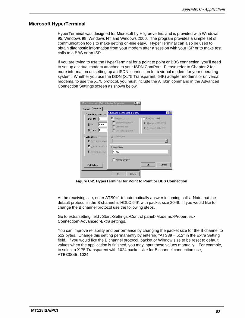
83
��������� �����������
MT128ISA/PCI
Microsoft HyperTerminal
HyperTerminal was designed for Microsoft by Hilgraeve Inc. and is provided with Windows95, Windows 98, Windows NT and Windows 2000. The program provides a simple set ofcommunication tools to make getting on-line easy. HyperTerminal can also be used toobtain diagnostic information from your modem after a session with your ISP or to make testcalls to a BBS or an ISP.
If you are trying to use the HyperTerminal for a point to point or BBS connection, you’ll needto set up a virtual modem attached to your ISDN ComPort. Please refer to Chapter 2 formore information on setting up an ISDN connection for a virtual modem for your operatingsystem. Whether you use the ISDN (X.75 Transparent, 64K) adapter modems or universalmodems, to use the X.75 protocol, you must include the ATB3n command in the AdvancedConnection Settings screen as shown below.
Figure C-2. HyperTerminal for Point to Point or BBS Connection
At the receiving site, enter ATS0=1 to automatically answer incoming calls. Note that thedefault protocol in the B channel is HDLC 64K with packet size 2048. If you would like tochange the B channel protocol use the following steps.
Go to extra setting field : Start>Settings>Control panel>Modems>Properties>Connection>Advanced>Extra settings.
You can improve reliability and performance by changing the packet size for the B channel to512 bytes. Change this setting permanently by entering “ATS39 = 512” in the Extra Settingfield. If you would like the B channel protocol, packet or Window size to be reset to defaultvalues when the application is finished, you may input these values manually. For example,to select a X.75 Transparent with 1024 packet size for B channel connection use,ATB30S45=1024.

84
�����������������������
MT128ISA/PCI
RVS-COM Lite
RVS-COM Lite is a CAPI compliant application (see Appendix B for more information aboutCAPI). Before installing RVS-COM Lite, the ISDN CAPI (ISDN driver) must be installed asdescribed in Chapter 2 of this manual. RVS-COM Lite can be used with Windows 95,Window 98, Windows NT and Windows 2000.
RVS-COM Lite allows you to take full advantage of the CAPI API by providing for processessuch as sending and receiving faxes, receiving voice mail, using a full-duplex sound card asa telephone, transferring files from PC to PC, using terminal emulation for BBS and onlinesystems as well as accessing the Internet via ISDN.
To install RVS-COM Lite, follow these steps:
1. Place the RVS-COM Lite CD in your CD drive.
2. If the Setup program doesn’t start by itself: from the Taskbar select Start>Run. EnterD:\SETUP.EXE (substitute the appropriate drive letter for your CD drive, if necessary).Click OK.
3. You will be asked to type in the key for your copy of RVS-COM. Depending on theversion of the program, you will find this information on a separate card or on the back ofthe CD sleeve. Click Setup to begin the installation.
4. The Setup program will prompt you for the installation folder and program group you’dlike RVS-COM installed to. When complete, click Finish.
5. Restart your computer if the program prompts you to do so.
6. The RVS-COM Lite Configuration Wizard starts automatically and will help you configureRVS-COM Lite.
7. For most applications, the default installation, Express Configuration is adequate.
8. When prompted, enter the ISDN Switch type, connection type, speed and phonenumber. When complete, click on Finish.
9. After installation, you may use the application by clicking on Start> Programs>RVS-COM Lite. To quickly familiarize yourself with RVS-COM Lite, open the onlinedocumentation.

85
Index
MT128ISA/PCI
Index
A
APIs 79Appendices 9Application Interfaces 10Applications 81AT COMMANDS 61
B
B-Channel Protocols 10Before You Begin 17BOD 18BRI Connections 16
C
Canadian Limitations Notice 77CAPI 17Windows 95 and the CAPI 30Windows 98 Multilinked Channel Access (CAPI) 39Windows 98 Single Channel Access (CAPI) 38Windows 98 and the CAPI Interface 38Class B Statement 77Codec 19COM Port Emulation 81Configure Port Usage 43Connections 16
D
Deteriming your modem type 18
E
EMC, Safety and Terminal Directive Compliance 78Environment Setup 14Error Messages 69
F
FCC 76Features 7, 8Firmware 73Frequently Asked Questions 64
G
Group Folder 20
H
Hardware 10HDLC 18HyperTerminal 83
I
Installation and Configuration 33Internet Access 14ISA 15Configuring for Your ISDN Switch 19ISDN BRI Line 12ISDN Configuration Display 20ISDN Group Folder 20ISDN Line Test 55ISDN LOG 68ISDN Monitor 55ISDN Switch Type 19
L
LED indicators 73LINETEST 68
M
Manual Organization 9Windows 95 Multilinked Channel Access 29MLPPP 18Model Number(s) 10MSN (POTS) 19
N
NDISWAN 17Windows 95 Single Channel Access (NDISWAN) 24Windows 98 Single Channel Access (NDISWAN) 34Windows 98 MLPChannel Access (NDISWAN) 35Windows NT MLPChannel Access (NDISWAN) 44Windows NT Single Channel Access (NDISWAN) 44Network Interface 10NT1 Connection 12
O
Ordering Accessories 74
P
PCI 15PPP 18Product Description 7Protocol 19
R
Remote Access Service 42Recording TA Information 72Registration 72Regulatory Agency Information 76Remote Access Services (RAS) Setup 43Windows 95 Removal of the ISDN Driver 32

86
MultiModemISDN User Guide
MT128ISA/PCI
Windows 98 Removal of the ISDN Drivers 40Result Code 67RVS-COM Lite 17, 84
S
S/T Interface Connector Specification 13SAD 19Safety Warnings 14Service 73Software versions 73Specifications, technical 10SPID 19Standby Time 19Supported Applications 10Switch Compatibility 10
T
Technical Support 72Terminator Setup 15Troubleshooting 64, 72TRUMPET Setup 81
U
U interface connector specification 13
V
VCOMM 17Windows 95 and the VCOMM 26Windows 98 MLP Channel Access (VCOMM) 37Windows 98 Single Channel Access (VCOMM) 36Windows 98 VCOMM (Virtual Modem) Interface 36Voice coding 10
W
Warranty 10, 72What Is in Your MultiModemISDN Package? 8Windows 2000 POTS/Voice Port Configuration 58Windows 2000 and the CAPI Interface 54Windows 2000 Installation and Configuration 49Windows 2000 Multilinked Access (NDISWAN) 53Windows 2000 MLPPChannel Access (CAPI) 55Windows 2000 Removal of the ISDN Drivers 59Windows 2000 Single Channel Access (CAPI) 54Windows 2000 Single Channel Access (NDISWA 52Windows 3.1 Application Interface Setup 21Windows 3.1 Installation and Configuration 20Windows 3.1 Removal of the ISDN Drivers 21Windows 95 and the NDISWAN interface 23Windows 95 Installation and Configuration 22Windows 95 Multilinked Channel Access 31Windows 95 MLP Channel Access (NDISWAN) 26Windows 95 Single Channel Access 28Windows 98 Installation and Configuration 33Windows NT and the CAPI Interface 46Windows NT Installation and Configuration 41
Windows NT Multilinked Channel Access (CAPI) 48Windows NT Removal of the ISDN Drivers 48Windows NT SIngle Channel Access (CAPI) 47
X
X.75 protocol 18