Embed Size (px)
Citation preview

AX400 Series User Guide
Models AX460 and AX466Single and Dual Input pH/Redox(ORP) Analyzers
7.00
Monitoring pH
7.00pH
pH
7.00
Monitoring pH
7.00pH
pH

ABB
The Company
We are an established world force in the design and manufacture of instrumentation for industrialprocess control, flow measurement, gas and liquid analysis and environmental applications.
As a part of ABB, a world leader in process automation technology, we offer customersapplication expertise, service and support worldwide.
We are committed to teamwork, high quality manufacturing, advanced technology and unrivalledservice and support.
The quality, accuracy and performance of the Company’s products result from over 100 yearsexperience, combined with a continuous program of innovative design and development toincorporate the latest technology.
The NAMAS Calibration Laboratory No. 0255 is just one of the ten flow calibration plantsoperated by the Company, and is indicative of our dedication to qualityand accuracy.
Use of Instructions
Warning.An instruction that draws attention to the risk of injury ordeath.
Caution.An instruction that draws attention to the risk of damage tothe product, process or surroundings.
Note.Clarification of an instruction or additional information.
Information.Further reference for more detailed information or technicaldetails.
Although Warning hazards are related to personal injury, and Caution hazards are associated with equipment or property damage, itmust be understood that operation of damaged equipment could, under certain operational conditions, result in degraded processsystem performance leading to personal injury or death. Therefore, comply fully with all Warning and Caution notices.
Information in this manual is intended only to assist our customers in the efficient operation of our equipment. Use of this manual forany other purpose is specifically prohibited and its contents are not to be reproduced in full or part without prior approval of theMarketing Communications Department.
Health and SafetyTo ensure that our products are safe and without risk to health, the following points must be noted:
1. The relevant sections of these instructions must be read carefully before proceeding.
2. Warning labels on containers and packages must be observed.
3. Installation, operation, maintenance and servicing must only be carried out by suitably trained personnel and in accordance with theinformation given.
4. Normal safety precautions must be taken to avoid the possibility of an accident occurring when operating in conditions of high pressure and/or temperature.
5. Chemicals must be stored away from heat, protected from temperature extremes and powders kept dry. Normal safe handling proceduresmust be used.
6. When disposing of chemicals ensure that no two chemicals are mixed.
Safety advice concerning the use of the equipment described in this manual or any relevant hazard data sheets (where applicable) may beobtained from the Company address on the back cover, together with servicing and spares information.
BS EN ISO 9001:1994
Cert. No. Q05907
REGISTERE
D
EN 29001 (ISO 9001)
Lenno, Italy – Cert. No. 9/90A
0255
Stonehouse, U.K.

1
CONTENTS
Section Page
1 INTRODUCTION .......................................................... 21.1 System Description ............................................ 21.2 AX400 Series Analyzer Options .......................... 2
2 OPERATION ................................................................. 32.1 Powering Up the Analyzer .................................. 32.2 Displays and Controls ........................................ 3
2.2.1 Key Functions ....................................... 32.3 Operating Page .................................................. 6
2.3.1 Single Input pH ..................................... 62.3.2 Dual Input pH ....................................... 72.3.3 Wash Function ...................................... 82.3.4 Single Input Redox (ORP) ..................... 92.3.5 Dual Input Redox (ORP) ...................... 102.3.6 Dual Input pH and Redox (ORP) ......... 11
3 OPERATOR VIEWS .................................................... 123.1 View Set Points ................................................ 123.2 View Outputs .................................................... 133.3 View Hardware ................................................. 133.4 View Software .................................................. 143.5 View Logbook .................................................. 143.6 View Clock ....................................................... 17
4 SETUP ........................................................................ 184.1 Sensor Calibration ............................................ 18
4.1.1 Set Buffer Type (pH Only) .................... 184.1.2 Set Up User Defined Buffers
(pH Only) ............................................. 204.1.3 Adjust Offset (Redox/ORP Only) ......... 214.1.4 Automatic and Manual, Single-
and Two-Point Calibration (pH Only) ... 224.1.5 Grab Calibration (pH Only) .................. 24
5 PROGRAMMING ........................................................ 255.1 Security Code .................................................. 255.2 Configure Display ............................................. 265.3 Configure Sensors ............................................ 275.4 Configure Alarms .............................................. 30
5.4.1 Wash Cycle Configuration(Applicable Only to Alarm 3) ................ 32
5.5 Configure Outputs ............................................ 345.6 Configure Clock................................................ 365.7 Configure Security ............................................ 375.8 Configure Logbook........................................... 375.9 Test Outputs and Maintenance ........................ 38
Section Page
6 INSTALLATION ........................................................... 396.1 Siting Requirements ......................................... 396.2 Mounting .......................................................... 40
6.2.1 Wall-/Pipe-mount Analyzers ................ 406.2.2 Panel-mount Analyzers ....................... 41
6.3 Connections, General ....................................... 426.3.1 Relay Contact Protection and
Interference Suppression .................... 436.3.2 Cable Entry Knockouts,
Wall-/Pipe-mount Analyzer ................. 446.4 Wall-/Pipe-mount Analyzer Connections .......... 45
6.4.1 Access to Terminals ............................ 456.4.2 Connections ....................................... 46
6.5 Panel-mount Analyzer Connections ................. 476.5.1 Access to Terminals ............................ 476.5.2 Connections ....................................... 48
7 CALIBRATION ............................................................ 497.1 Equipment Required ......................................... 497.2 Preparation ....................................................... 497.3 Factory Settings ............................................... 50
8 SIMPLE FAULT FINDING ........................................... 558.1 Error Messages ................................................ 558.2 Calibration Fail Message or
no Response to pH/Redox Changes................ 558.3 Checking the Temperature Input ...................... 55
APPENDIX A ....................................................................... 56A1 Buffer Solutions ................................................ 56
SPECIFICATION .................................................................. 59

2
1.1 System DescriptionThe AX400 Series pH/Redox (ORP) analyzers and associatedelectrode systems have been designed for continuousmonitoring and control of pH and Redox (ORP). The electrodesystem can be standardized to the analyzer using the built-incalibration facility and a single point buffering facility provideseasy re-calibration after initial standardization.
The analyzer is available in wall-/pipe-mount or panel-mountversions with either one or two programmable, pH or Redox(ORP) input channels, each with its own associated temperatureinput channel. When making temperature compensatedmeasurements, the sample temperature is sensed by aresistance thermometer (Pt100, Pt1000 or Balco 3K) mountedin the electrode system.
The analyzer can be configured for and connected to either astandard pH input (single, high impedence input >1013Ω) ordifferential pH input (dual, high impedence inputs, both >1013Ω).
Differential pH input is designed for use with pH electrodesystems that incorporate a solution earth (ground) rod. Themeasuring electrode and reference electrode signals aremeasured separately using two, high impedence amplifiers andcompared with the solution earth (ground) potential. Thedifference between the results is the value used for the pHmeasurement.
All models incorporate a wash facility for system cleaning; thealarm 3 relay can be configured to control the wash systemeither automatically or manually. The relay can be programmedto deliver either a continuous or pulsed signal to control anexternal power supply to a solenoid or pump and the frequency,duration and recovery time for the wash cycle are alsoprogrammable. During a wash cycle, the analog output value isheld in its pre-cycle condition.
Analyzer operation and programming are performed using fivetactile membrane keys on the front panel. Programmedfunctions are protected from unauthorized alteration by a four-digit security code.
1 INTRODUCTION
1.2 AX400 Series Analyzer OptionsTable 1.1 shows the range of configurations that are possible forthe AX400 Series analyzers. The analyzer automatically detectsthe type of input board fitted for each input and displays only theframes applicable to that input board type. If no input board isfitted for Sensor B input, Sensor B frames are not displayed.
rebmuNledoMrezylanA rezylanAfonoitpircseD ArosneS BrosneS
014XA 000,01ot0(ytivitcudnoCtupnIelgniS µ )mc/S ytivitcudnoC elbacilppAtoN
114XA 000,01ot0(ytivitcudnoCtupnIlauD µ )mc/S ytivitcudnoC ytivitcudnoC
614XA )PRO(xodeR/HpdnaytivitcudnoCtupnIlauD ytivitcudnoC )PRO(xodeR/Hp
054XA )PSU(ytivitcudnoCtupnIelgniS ytivitcudnoC elbacilppAtoN
554XA )PSU(ytivitcudnoCtupnIlauD ytivitcudnoC ytivitcudnoC
064XA )PRO(xodeR/HptupnIelgniS )PRO(xodeR/Hp elbacilppAtoN
664XA )PRO(xodeR/HptupnIlauD )PRO(xodeR/Hp )PRO(xodeR/Hp
Table 1.1 AX400 Series Analyzer Options

3
Fig. 2.1 Location of Controls and Displays
Fig. 2.2 Membrane Key Functions
0.00
Monitoring pH
0.00
AlarmLEDs
DisplayLines
LowerDisplay Line
Membrane Keys
pH Units
Menu Key
Sidescroll Key
Downscroll Key
Up Key
Down Key
pH
B – Advancing to Next Page
C – Moving Between Parameters
D – Adjusting and Storing a Parameter Value
E – Selecting and Storing a Parameter Choice
A – Moving Between Menus
For majorityof parameters
Parameter 1Parameter 2Parameter 3Parameter 4
Page 1Parameter 1Parameter 2Parameter 3
Page 2
Advance tonext page
or
Parameter 1
Parameter 2Parameter 3
Page X
Parameter 4
Advance tonext parameter
New value isstored automatically
Parameter Value Adjust
Parameter XYZ
Select
New value isautomatically stored
Menu 1
Menu 2
Advance tonext menu
2.1 Powering Up the Analyzer
Caution. Ensure all connections are madecorrectly, especially to the earth stud – see Section 6.3.
1) Ensure the input sensor(s) is/are connected correctly.
2) Switch on the power supply to the analyzer. A start-upscreen is displayed while internal checks are performed,then the Operating Page (see Section 2.3) is displayed as thepH or Redox (ORP) monitoring operation starts.
2.2 Displays and Controls – Fig. 2.1The display comprises two rows of 41/2 digit, 7-segment digitaldisplays, which show the actual values of the measuredparameters and alarm set points, and a 6-character dot matrixdisplay showing the associated units. The lower display line is a16-character dot matrix display showing the programminginformation.
2.2.1 Key Functions
2 OPERATION

4
…2 OPERATION
Use the MenuKey to scroll
throughthe Menus
Available only if theanalog option board is fitted
Key
VIEW SETPOINTS VIEW OUTPUTS VIEW HARDWARE VIEW SOFTWARE
A1: Setpoint Analog Output 1 Sensor A Module AX400/2000 Issue
A2: Setpoint Analog Output 2 Sensor B Module
A3: Setpoint Analog Output 3 Option Board
A4: Setpoint Analog Output 4
A5: Setpoint
Security Code
SENSOR CAL. Cal. User Code Sensor Cal. A
A: Buffer Method
A: Immerse Buf.1
A: Cal. Buffer 1
A: Immerse Buf.2
A: Cal. Buffer 2
A: Calibration
CONFIG.SENSORS
B: Probe Type
B: Diff. Input
B: Electrode
B: Temp. Comp
B: Temp. Sensor
B: Preset Temp.
B: Sample Comp.
CONFIG. DISPLAY Set Language Set Temp. Units Set Backlight
LED BacklightTemp. UnitsEnglish
B: Sample Coeff.
Use the Sidescroll Key to scroll through the Pages within each Menu
To CONFIG. ALARMS(see Fig. 2.3B)
Use the DownscrollKey to scroll through
the Parameterswithin each Page
OPERATING PAGE
Section 2.3, Page 6 Section 3.1, Page 12 Section 3.2, Page 13 Section 3.3, Page 13 Section 3.4, Page 14 Section 3.5, Page 14
Section 4.1, Page 18
Section 5.1, Page 25
Section 5.2, Page 26
Section 5.3, Page 27
Section 3.6, Page 17
Set Auto Buffers
Buffer Type
Set Buffer 1
Set Buffer 2
A: Slope & Check
Sensor Cal. B
B: Buffer Method
B: Immerse Buf.1
B: Cal. Buffer 1
B: Immerse Buf.2
B: Cal. Buffer 2
B: Calibration
B: Slope & Check
B: Set Min Slope
Config. Sensor BConfig. Sensor A
A: Probe Type
A: Diff. Input
A: Temp. Comp
A: Temp. Sensor
A: Preset Temp.
A: Sample Comp.
A: Sample Coeff.
A: Set Min Slope
A: Electrode
A: Enter Point 1
A: Enter Point 2
B: Enter Point 1
A: Enter Point 5
A: Enter Point 4
A: Enter Point 3
B: Enter Point 2
B: Enter Point 5
B: Enter Point 4
B: Enter Point 3
#### 100% ####
#### 100% ####
#### 100% ####
#### 100% ####
Alarms
Errors
Power
Cals
VIEW LOGBOOK
Dual input analyzer only
VIEW CLOCK
Date 01:01:03
Time 12:00
Note. Sensor calibration frames shownabove are for 2-point calibration only.For other calibration options, refer to Section 4.1.
A: Enable Cals B: Enable Cals* *
* Applicable only if Probe Type is set to Redox or ORP
Fig. 2.3A Overall Programming Chart

5
2 OPERATION…
CONFIG.ALARMS Config. Alarm 1
A1: Type
A1: Assign
A1: Failsafe
A1: Action
A1: Setpoint
A1: Hysteresis
A1: Delay
Config. Alarm 2
A2: Type
A2: Assign
A2: Failsafe
A2: Action
A2: Setpoint
A2: Hysteresis
A2: Delay
A3: Assign
A3: Failsafe
A3: Action
A3: Setpoint
A3: Hysteresis
A3: Delay
CONFIG.OUTPUTS Config. Output 1
AO1: Assign
AO1: Range
AO1: Span Value
AO1: Zero Value
CONFIG.SECURITY Alter Sec.Code
Alter Cal.Code
TEST/MAINTENANCE Test Outputs
Test Output 1
Test Output 2
Maintenance
Hold Outputs
To FACTORY SETTINGS(see Section 7.3, Page 50)
Config. Alarm 3
A3: Type
AO1: Default
AO1: Default Val
Available only if theanalog option board is fitted
Key
Config. Output 2
AO2: Assign
AO2: Range
AO2: Span Value
AO2: Zero Value
AO2: Default
AO2: Default Val
Config. Output 3
AO3: Assign
AO3: Range
AO3: Span Value
AO3: Zero Value
AO3: Default
AO3: Default Val
Test Output 3
Test Output 4
Use the Sidescroll Key to scroll through the Pages within each Menu
Section 5.4, Page 30
Section 5.5, Page 34
Section 5.7, Page 37
Section 5.9, Page 38
Use the MenuKey to scroll
throughthe Menus
Use the DownscrollKey to scroll through
the Parameterswithin each Page
CONFIG.CLOCK Set Clock?
Format dd/mm/yy
Date 01:01:02
Time 12:00
Press To AbortPress To Set
Section 5.6, Page 36
CONFIG.LOGBOOK
Section 5.8, Page 37
Logbook
Config. Alarm 4
A4: Type
A4: Assign
A4: Failsafe
A4: Action
A4: Setpoint
A4: Hysteresis
A4: Delay
Config. Alarm 5
A5: Type
A5: Assign
A5: Failsafe
A5: Action
A5: Setpoint
A5: Hysteresis
A5: Delay
Config. Output 4
AO4: Assign
AO4: Range
AO4: Span Value
AO4: Zero Value
AO4: Default
AO4: Default Val
Wash Frequency
Wash Duration
Recovery Period
Wash Mode*
* Applicable only to Alarm 3
Fig. 2.3B Overall Programming Chart

6
Measured ValuespH.
Temperature.
Measured Millivolts
Millivolts.
% Slope and pH Check Value% slope value.A value between the programmed minimum % slope value (see Set Min Slope in theCONFIG. SENSORS page – Section 5.3) and 105% is displayed. If the value is outside theselimits, check the electrode system.
pH check value (zero point).Displayed as an additional indication of pH electrode system condition; 7pH is theoptimum value for glass electrodes and 0pH for Antimony electrodes.
Alarm 3 set to Wash (A3: Type, Section 5.4) – see Section 2.3.3.Alarm 3 not set to Wash.
2.3 Operating Page
2.3.1 Single Input pH
…2 OPERATION
Monitoring pH
7.00pH
24.4Deg.C
Wash Function
Monitoring pH
Millivolts
404mV
A: Slope & Check
100.0%
7.00pH

7
Monitoring pH
7.00pH
7.00pH
Wash Function
Monitoring pH
Temperature
25.6Deg.C
Millivolts
404mV
A: Slope & Check
100.0%
7.00pH
24.4Deg.C
-256mV
B: Slope & Check
%
pH
100.07.00
Measured pHSensor A.
Sensor B.
Measured TemperatureSensor A.
Sensor B.
Measured MillivoltsSensor A.
Sensor B.
Sensor A % Slope and pH Check Value% slope value.A value between the programmed minimum % slope value (see Set Min Slope in theCONFIG. SENSORS page – Section 5.3) and 105% is displayed. If the value is outside theselimits, check the electrode system.
pH check value (zero point).Displayed as an additional indication of pH electrode system condition; 7pH being theoptimum value for glass electrodes and 0pH for Antimony electrodes.
Sensor B % Slope and pH Check Value% slope value.
See Sensor A above.pH check value (zero point).
Alarm 3 set to Wash (A3: Type, Section 5.4) – see Section 2.3.3.Alarm 3 not set to Wash.
…2.3 Operating Page
2.3.2 Dual Input pH
2 OPERATION…

8
…2.3 Operating Page
2.3.3 Wash Function
Note. Applicable only if Alarm 3 (A3: Type) is set to Wash in the CONFIG. ALARMS page – see Section 5.4.
Wash FunctionOff – Wash function off. Lower display line of Operating Page shows
WASH INHIBITED.On – Wash function controlled automatically. Lower display line of Operating Page
shows WASH IN PROGRESS.Manual – Enables wash function to be initiated manually – see below.
Caution. Set Wash Function to Off before removing the sensor from the process.
See Section 3.1.
Probe Type set to pH (for either sensor if dual input analyzer) – see Section 5.3.See Section 4.1.
Probe Type set to Redox or ORP (for both sensors in any combination if dual input analyzer)– see Section 5.3.
Sensor calibration enabled (Section 5.3) – see Section 4.1.Alter Sec. Code not set to zero (Section 5.7) – see Section 5.1.Alter Sec. Code set to zero (Section 5.7) – see Section 5.2.
Wash Function set to Manual – see below.Wash Function not set to Manual.
Press to Wash (Manual Wash only)
Press to Wash and Press to Abort are shown alternately on the lower display line.
Press the key to initiate the wash cycle. The display returns to the top ofthe Operating Page and the lower display line shows WASH IN PROGRESS untilthe wash cycle is completed. The Wash Function selection resets to the onethat was set before Manual was selected.
Press the key to abort the wash cycle. The display returns to the top ofthe Operating Page.
VIEW SETPOINTS
SENSOR CAL.
Wash Function
-----
ManualOnOff
-----Press To WashPress To Abort
SENSOR CAL.
Security Code
CONFIG. DISPLAY
Press To Wash
MONITORING PH
WASH IN PROGRESS
MONITORING PH
…2 OPERATION

9
…2.3 Operating Page
2.3.4 Single Input Redox (ORP)
Measured ValuesMillivolts.
Temperature.
Note. If Probe Type is set to ORP in the CONFIG. SENSORS page (see Section 5.3),the lower display line shows Monitoring ORP.
Sensor A OffsetDisplays the offset value for the sensor set in A: Adjust Offset – see Section 4.1.3.
Alarm 3 set to Wash (A3: Type, Section 5.4) – see Section 2.3.3.Alarm 3 not set to Wash.
Monitoring Redox
404mV
25.6Deg.C
A: mV Offset
0mV
Wash Function
Dual Redox
2 OPERATION…

10
Measured MillivoltsSensor A.
Sensor B.
Note. If Probe Type for both Sensor A and Sensor B is set to ORP in theCONFIG. SENSORS page (see Section 5.3), the lower display line shows Dual ORP.
Sample TemperatureSensor A.
Sensor B.
Note. The measured temperature is displayed only if Temp. Sensor is not set to Nonein the CONFIG. SENSORS page – see Section 5.3.
Sensor A OffsetDisplays the offset value for Sensor A set in A: Adjust Offset – see Section 4.1.3.
Sensor B OffsetDisplays the offset value for Sensor B set in B: Adjust Offset – see Section 4.1.3.
Alarm 3 set to Wash (A3: Type, Section 5.4) – see Section 2.3.3.Alarm 3 not set to Wash.
…2.3 Operating Page
2.3.5 Dual Input Redox (ORP)
…2 OPERATION
Dual Redox
404mV
-256
Temperature
25.6Deg.C
24.4Deg.C
mV
A: mV Offset
0mV
B: mV Offset
0mV
Wash Function
Dual Redox

11
…2.3 Operating Page
2.3.6 Dual Input pH and Redox (ORP)
Measured pH and MillivoltsSensor A.
Sensor B.
Note. The Probe Type for Sensors A and B can be set to any combination of pH,Redox or ORP in the CONFIG. SENSORS page – see Section 5.3. The display indicationschange depending on Probe Type settings, e.g. if Sensor A is set to Redox and Sensor Bto pH, the lower display shows Redox/pH.
Measured TemperatureSensor A.
Sensor B.
Note. The measured temperature is displayed only if Temp. Sensor is not set to Nonein the CONFIG. SENSORS page – see Section 5.3.
Measured MillivoltsSensor A.
Sensor B.
Sensor B OffsetDisplays the offset value for Sensor B set in B: Adjust Offset – see Section 4.1.3.
Sensor A % Slope and pH Check Value% slope value.A value between the programmed minimum % slope value (see Set Min Slope in theCONFIG. SENSORS page – Section 5.3) and 105% is displayed. If the value is outside theselimits, check the electrode system.
pH check value (zero value).Displayed as an additional indication of pH electrode system condition; 7pH is theoptimum value for glass electrodes and 0pH for Antimony electrodes.
Alarm 3 set to Wash (A3: Type, Section 5.4) – see Section 2.3.3.Alarm 3 not set to Wash.
pH/Redox
7.00pH
-256mV
Temperature
25.6Deg.C
Millivolts
404mV
A: Slope & Check
100.0%
7.00pH
24.4Deg.C
-256mV
B: mV Offset
0mV
Wash Function
pH/Redox
2 OPERATION…

12
3 OPERATOR VIEWS
View Set PointsThis page shows alarm set points. The value of each of the set points is shown, togetherwith the name of the parameter it is assigned to.
Set point values and relay/LED actions are programmable – see Section 5.4.
Sensor A (pH), Alarm 1 Set Point
Sensor A (Temperature), Alarm 2 Set Point
Sensor B (pH), Alarm 3 Set Point – Dual input analyzers only
Sensor B (Temperature), Alarm 4 Set Point – Dual input analyzers only
Note. Alarm 4 is available only if the optional analog output board is fitted.
Alarm 5 Set Point
Note. Alarm 5 is available only if the optional analog output board is fitted.
Return to main menu.
Sensor calibration enabled (Section 5.3) – see Section 4.1.Alter Sec. Code not set to zero (Section 5.7) – see Section 5.1.Alter Sec. Code set to zero (Section 5.7) – see Section 5.2.
8.30pH
A1: Setpoint
Sen.A
Temp.A
VIEW SETPOINTS
-----
35.0Deg.C
A2: Setpoint
Sen.B
6.80A3: Setpoint
Temp.B
55.0Deg.C
A4: Setpoint
-----Off
A5: Setpoint
VIEW OUTPUTS
SENSOR CAL.
Security Code
CONFIG. DISPLAY
VIEW SETPOINTS
pH
3.1 View Set Points
Note. The parameter names and units of measurement displayed in the View Set Points page depend on the Probe Typesettings for Sensors A and B in the CONFIG. SENSORS page – see Section 5.3. Those shown below are given as examples only.

13
3 OPERATOR VIEWS…
3.2 View Outputs
Theoretical Analog OutputThere are up to four analog outputs, each showing information for one sensor.
Note. Analog outputs 3 and 4 are available only if the optional analog output boardis fitted.
Live current output value being retransmitted.
Current output shown as a percentage of full scale for the output range set in CONFIG.OUPUTS – see Section 5.6.
See Section 3.3.
Sensor calibration enabled (Section 5.3) – see Section 4.1.Alter Sec. Code not set to zero (Section 5.7) – see Section 5.1.Alter Sec. Code set to zero (Section 5.7) – see Section 5.2.
Analog Output 2 – repeat for output 2 (and outputs 3 and 4 if optionalanalog output board fitted).
3.3 View Hardware
Sensor A ModuleShows the type of input board fitted to the analyzer for the Sensor A input.
Sensor B Module – Dual input analyzers onlyShows the type of input board fitted to the analyzer for the Sensor B input.
Option BoardShows the type of option board fitted to the analyzer (if applicable).
See Section 3.4.
Sensor calibration enabled (Section 5.3) – see Section 4.1.Alter Sec. Code not set to zero (Section 5.7) – see Section 5.1.Alter Sec. Code set to zero (Section 5.7) – see Section 5.2.
50.0%
Analog Output 1
12.00mA
VIEW OUTPUTS
-----
VIEW HARDWARE
SENSOR CAL.
Security Code
CONFIG. DISPLAY
Analog Output 2
pH
pH
-----Sensor A Module
VIEW HARDWARE
-----
Option Board
-----Sensor B Module
-----OffModbusAnalog
VIEW SOFTWARE
SENSOR CAL.
Security Code
CONFIG. DISPLAY
VIEW HARDWARE

14
…3 OPERATOR VIEW
3.4 View Software
IssueShows the version number of the operating software.
Optional analog output board fitted and Logbook set to On in the CONFIG.LOGBOOK page (Section 5.8) – see Section 3.5.
Operating Page (optional analog output board not fitted) – see Section 2.3.
Sensor calibration enabled (Section 5.3) – see Section 4.1.Alter Sec. Code not set to zero (Section 5.7) – see Section 5.1.Alter Sec. Code set to zero (Section 5.7) – see Section 5.2.
The logbook stores data entries for alarm events, sensor errors, power failures and pHcalibration information.
View LogbookUse the and keys to access the Alarms logbook.
AlarmsThe Alarms logbook contains up to 10 entries (entry 1 is the most recent), each comprisingan alarm number, alarm state (On or Off) and the date and time of the occurrence.
Optional analog input board fitted – see Section 3.6.
Sensor calibration enabled (Section 5.3) – see Section 4.1.Alter Sec. Code not set to zero (Section 5.7) – see Section 5.1.Alter Sec. Code set to zero (Section 5.7) – see Section 5.2.
Advance to entries 2 to 10.
Note. If no more entries are stored, the display shows No More Entries.
1.00AX400/2000 Issue
VIEW SOFTWARE
-----
VIEW LOGBOOK
SENSOR CAL.
Security Code
CONFIG. DISPLAY
VIEW SOFTWARE Monitoring pH
-----11:09:02 12:34
VIEW LOGBOOK
-----
VIEW CLOCK
SENSOR CAL.
Security Code
CONFIG. DISPLAY
A1
-----VIEW LOGBOOK
1
2
CalsPowerErrorsAlarms
A1
On
3.5 View Logbook
Note. The VIEW LOGBOOK function is available only if the optional analog output board is fitted and Logbook is set to On inthe CONFIG. LOGBOOK page – see Section 5.8.

15
3 OPERATOR VIEWS…
…3.5 Logbook
View LogbookUse the and keys to access the Errors logbook.
ErrorsThe Errors logbook contains up to 5 entries (entry 1 is the most recent), each comprisingthe sensor letter, error number and the date and time of the occurrence.
Optional analog input board fitted – see Section 3.6.
Sensor calibration enabled (Section 5.3) – see Section 4.1.Alter Sec. Code not set to zero (Section 5.7) – see Section 5.1.Alter Sec. Code set to zero (Section 5.7) – see Section 5.2.
Advance to entries 2 to 5.
Note. If no more entries are stored, the display shows No More Entries.
View LogbookUse the and keys to access the Power logbook.
PowerThe Power logbook contains up to 2 entries (entry 1 is the most recent), each comprisingthe power state (On or Off) and the date and time of the occurrence.
Optional analog input board fitted – see Section 3.6.
Sensor calibration enabled (Section 5.3) – see Section 4.1.Alter Sec. Code not set to zero (Section 5.7) – see Section 5.1.Alter Sec. Code set to zero (Section 5.7) – see Section 5.2.
Advance to entry 2.
Note. If no more entries are stored, the display shows No More Entries.
-----
-----
11:09:02 12:34
VIEW CLOCK
SENSOR CAL.
Security Code
CONFIG. DISPLAY
Sen.A
VIEW LOGBOOK
Errors
1 Sen.A
Pt100
2
AlarmsCalsPowerErrors
-----11:09:02 12:34
VIEW CLOCK
SENSOR CAL.
Security Code
CONFIG. DISPLAY
-----VIEW LOGBOOK
1Off
2
ErrorsAlarmsCalsPower

16
…3.5 Logbook
View LogbookUse the and keys to access the Cals logbook.
CalibrationThe Cals logbook contains up to 5 entries (entry 1 is the most recent), each comprising 2frames. Frame 1 contains the entry number, sensor letter and the calibration pass/failindication.
Frame 2 contains the % slope value, the pH check value and the date and time of theoccurrence.
Optional analog input board fitted – see Section 3.6.
Sensor calibration enabled (Section 5.3) – see Section 4.1.Alter Sec. Code not set to zero (Section 5.7) – see Section 5.1.Alter Sec. Code set to zero (Section 5.7) – see Section 5.2.
Advance to entries 2 to 5.
Note. If no more entries are stored, the display shows No More Entries.
VIEW CLOCK
-----Calibration
-----VIEW LOGBOOK
1 Sen.A
Passed
11:09:02 12:34
SENSOR CAL.
Security Code
CONFIG. DISPLAY
Sen.A
100.0 %
pH
2
7.00
PowerErrorsAlarmsCals
…3 OPERATOR VIEWS

17
DateShows the current date.
TimeShows the current time.
Operating Page – see Section 2.3
Sensor calibration enabled (Section 5.3) – see Section 4.1.Alter Sec. Code not set to zero (Section 5.7) – see Section 5.1.Alter Sec. Code set to zero (Section 5.7) – see Section 5.2.
3.6 View Clock
Note. The VIEW CLOCK function is available only if the optional analog output board is fitted.
3 OPERATOR VIEWS
-----Date 01:01:01
VIEW CLOCK
-----
-----Time 12:00
Monitoring pH
SENSOR CAL.
Security Code
CONFIG. DISPLAY
VIEW CLOCK

18
4 SETUP
4.1 Sensor Calibration
SENSOR CAL.
-----
Cal. User Code
0000
Set Auto Buffers
Sensor Cal. A
4.1.1 Set Buffer Type (pH Only)
Sensor Calibration
Note. When Probe Type for either sensor (Sensor A only if single-input) is set toRedox or ORP, this section is applicable only if Enable Cals. for that sensor is set to Yes –see Section 5.3.
Sensor Calibration Security CodeEnter the required code number (between 0000 and 19999), to gain access to the sensorcalibration procedure. If an incorrect value is entered, access to subsequent calibrationpages is prevented and the display reverts to the SENSOR CAL. page.
Note. Applicable only if Alter Cal. Code is not set to zero – see Section 5.7.
Probe Type set to pH (for either sensor if dual input analyzer) – continuedbelow.
Probe Type set to Redox or ORP (for both sensors if dual input analyzer) –continued on page 21.
Set Auto Buffers
Continued on Page 21.
Alter Sec. Code not set to zero (Section 5.7) – see Section 5.1.Alter Sec. Code set to zero (Section 5.7) – see Section 5.2.
Continued below.
Buffer TypeSelect the relevant type of buffer solution (see Appendix A):ABB – ABB supplied buffer solution.NIST – NIST buffer solution.DIN – DIN 19266 buffer solution.MERCK – MERCK buffer solutionTECH – US Technical buffer solutionUser – Buffer solution with a user defined pH value – see Section 4.1.2.
Buffer Type not set to User – continued on next page.Buffer Type set to User – see Section 4.1.2.
Set Auto Buffers
-----
Sensor Cal. A
SECURITY CODE
CONFIG. DISPLAY
Buffer Type
-----
UserTECH.MERCKDINNISTABB
Set Buffer 1
Buffer Type
A: Enter Point 1

19
Set Buffer 1Set the pH value of the buffer 1 solution – see Appendix A for pH tables.
Set Buffer 2Set the pH value of the buffer 2 solution.
Note. The solution selected for buffer 2 must be at least 2pH value greater than thatselected for buffer 1, e.g. if buffer 1 is set to 7pH, buffer 2 must be set to at least 9pH.
Set Buffer 1-----
Set Buffer 2
9.18pH-----
Set Auto Buffers
4.O1pH
…4.1 Sensor Calibration
…4.1.1 Set Buffer Type (pH Only)
4 SETUP…

20
Solution A: Enter point 1 (to 5)Deg.C and Adjust are shown alternately on the upper display line. Using the and keys, adjust the temperature reading (in 5° increments) to the first of the temperatures onthe pH/temperature curve.
pH and Adjust are shown alternately on the center display line. Using the and keys,adjust the pH reading (in 0.01pH) to the pH reading that corresponds to the temperaturereading entered above.
Notes.1) For accurate calibration, it is important to repeat the above for buffer solution A at all 5
points along the pH/temperature curve.
2) The displayed temperature value increases automatically by 5°C from the value set forthe previous point. The setting may be increased but not decreased.
Solution B: Enter point 1 (to 5)Solution B set up is identical to solution A set up.
Note. For accurate calibration, it is important to repeat the above for buffer solution Bat all 5 points along the pH/temperature curve.
The analyzer calculates the pH/temperature relationship from the data entered.
See Section 4.1.3.
Alter Sec. Code not set to zero (Section 5.7) – see Section 5.1.Alter Sec. Code set to zero (Section 5.7) – see Section 5.2.
…4.1 Sensor Calibration
4.1.2 Set Up User Defined Buffers (pH Only)
A: Enter point 5
35.0Deg.C
4.02pH
Sensor Cal. A
SECURITY CODE
Set Auto Buffers
Buffer Type set to User (see section 4.1.1)
A: Enter point 1
15.0Deg.C
0.00pH
B: Enter point 5
35.0Deg.C
4.02pH
B: Enter point 1
15.0Deg.C
3.99pH
CONFIG. DISPLAY
A: Enter point 1
15.0Deg.C
3.99pH
…4 SETUP

21
Calibrate Sensor A
Sensor B (dual input analyzers only) calibration is identical to Sensor Acalibration.
Probe Type for Sensor B (dual input analyzers only) set to Redox or ORP andEnable Cals. set to No (see Section 5.3) – return to top of page.
Alter Sec. Code not set to zero (Section 5.7) – see Section 5.1.Alter Sec. Code set to zero (Section 5.7) – see Section 5.2.
Probe Type set to Redox or ORP – continued below.Probe Type set to pH – see Section 4.1.4.
Adjust Offset (ORP/Redox probes only)mV and Adjust are shown alternately on the upper display line. Use the and keys toadjust the upper display line to the required offset value for the process.
Return to main menu.
Alter Sec. Code not set to zero (Section 5.7) – see Section 5.1.Alter Sec. Code set to zero (Section 5.7) – see Section 5.2.
Return to top of page.
…4.1 Sensor Calibration
4.1.3 Adjust Offset (Redox/ORP Only)
Sensor Cal. A
-----
A: Adjust Offset
407mV
0mV
SENSOR CAL
Sensor Cal. B
A: Adjust Offset
A: Buffer Method
SECURITY CODE
CONFIG. DISPLAY
Sensor Cal. A
CONFIG. SENSORS
SECURITY CODE
CONFIG. DISPLAY
4 SETUP…

22
…4 SETUP
…4.1 Sensor Calibration
4.1.4 Automatic and Manual, Single- and Two-Point Calibration (pH Only)
Sensor A: Buffer Method (pH probes only)Select the type of calibration required:Auto 1-Pt – Automatic, single-point calibrationAuto 2-Pt – Automatic, two-point calibrationMan 1-Pt – Manual, single-point calibrationMan 2-Pt – Manual, two-point calibrationGrab – Adjust the display to match the measured pH value of a sample.
Anything other than Grab selected – continued below.Grab selected, see Adjust Value on page 24.
Calibrate Buffer (Single-Point Calibration) or Calibrate Buffer 1(Two-Point Calibration)Immerse sensor A in the buffer solution.
If a Manual calibration has been selected, set the upper display to the temperature-corrected pH value of the chosen solution (see the datasheet provided with the solution).
Press the key to initiate calibration.
Note. To abort calibration, press the key again at any time before calibration iscomplete – see below.
The center display line shows the sensor e.m.f.As calibration procedes, a progress indicator appears in the lower display line. When astable e.m.f. is detected, the lower display line shows ##### 100% #####.
The display then changes for 2 seconds to show the temperature corrected buffer valuein the upper display line, then advances automatically to the next parameter.
Two-point calibration selected – continued on next page.Single-point calibration selected – continued on next page.
Abort Calibration
Select Yes or No.
Yes selected – the display returns to the top of the Calibration Page.No selected – calibration continues.
#### 100% ####
175mV
A: Immerse Buf.2
A: Calibration
A: Abort Cal.
-----Yes
A: SENSOR CAL.
A: Immerse Buf.2
A: Immerse Buf.1
4.00pH
Deg.C25.0
A: Adjust Value
A: Immerse Buf 1
A: Buffer Method
Auto
-----1-Pt
A: Cal. Buffer 1
4.01pH

23
…4.1 Sensor Calibration
…4.1.4 Automatic and Manual, Single- and Two-Point Calibration (pH Only)
4 SETUP…
SECURITY CODE
CONFIG. DISPLAY
Sensor Cal. A
A: Immerse Buf.2
9.18pH
20.0Deg.C
#### 100% ####
-128mV
A: Calibration
-----Passed
A: Slope & Check
100.0%
7.00pH
2-Pt cal
1-Ptcal
A: Slope & Check
SECURITY CODE
CONFIG. DISPLAY
A: Cal. Buffer 1
4.01pH
noitarbilaCegasseM
.niM .xaM noitanalpxE noitcA
DESSAP %07ot04 %501 detpeccaerastneiciffeocnoitarbilacwenehT enoN
EPOLSWOLLAC %09ot06 %09ot06 detpeccaerastneiciffeocnoitarbilacwenehT–deugitafgnimoceberariapedortceleehT
dednemmocersitnemecalper
DELIAFLACHP %0 %07ot04ehtdnaderongierastneiciffeocnoitarbilacwenehT
desuerastneiciffeocnoitarbilacdoognwonktsalehtfI.gnireffubtaeperdnaseulavreffubkcehC
sedortceleehtecalper,stsisreptluaf
Table 4.1 Calibration Messages
Calibrate Buffer 2 (Two-Point Calibration only)Immerse Sensor A in the second buffer solution and continue as for Buffer 1.
Note. To abort calibration, press the key again at any time before calibration iscomplete – see previous page.
The center display line shows the sensor e.m.f.As calibration procedes, a progress indicator appears in the lower display line. When astable e.m.f. is detected, the lower display line shows ##### 100% #####.
The display then changes for 2 seconds to show the temperature corrected buffer valuein the upper display line, then advances automatically to the next parameter.
Calibration MessageSee Table 4.1 for details of calibration messages.
Alter Sec. Code not set to zero (Section 5.7) – see Section 5.1.Alter Sec. Code set to zero (Section 5.7) – see Section 5.2.
Provides indication of electrode condition – continued below.
Slope Value% slope value.A value between the programmed minimum % slope value (see Set Min Slope in theCONFIG. SENSORS page – Section 5.3) and 105% is displayed. If the value is outside theselimits, check the electrode system.
pH check value.Displayed as an additional indication of electrode system condition; 7pH is the optimumvalue for glass electrodes and 0pH for Antimony electrodes.
Alter Sec. Code not set to zero (Section 5.7) – see Section 5.1.Alter Sec. Code set to zero (Section 5.7) – see Section 5.2.
24
…4 SETUP
A: Adjust Value
9.18pH
25.0Deg.C
CONFIG. SENSORS
SECURITY CODE
CONFIG. DISPLAY
A: Slope & Check
SECURITY CODE
CONFIG. DISPLAY
Sensor Cal. A
A: Slope & Check
100.0%
7.00pH
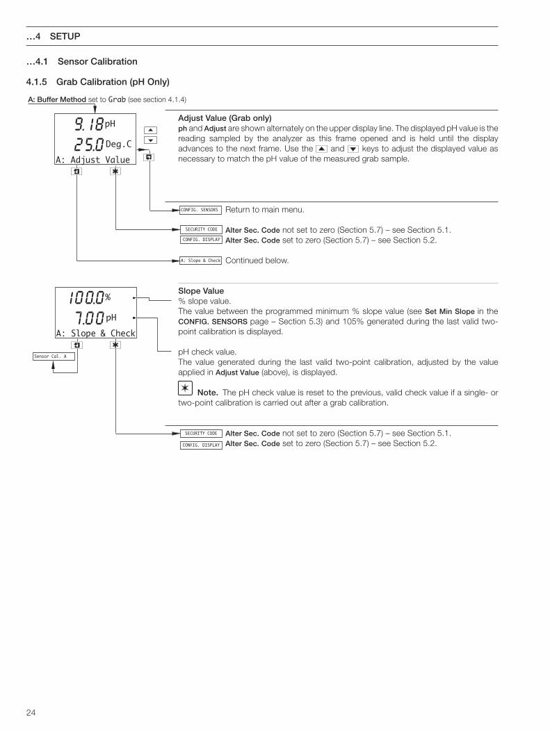
A: Buffer Method set to Grab (see section 4.1.4)
Adjust Value (Grab only)ph and Adjust are shown alternately on the upper display line. The displayed pH value is thereading sampled by the analyzer as this frame opened and is held until the displayadvances to the next frame. Use the and keys to adjust the displayed value asnecessary to match the pH value of the measured grab sample.
Return to main menu.
Alter Sec. Code not set to zero (Section 5.7) – see Section 5.1.Alter Sec. Code set to zero (Section 5.7) – see Section 5.2.
Continued below.
Slope Value% slope value.The value between the programmed minimum % slope value (see Set Min Slope in theCONFIG. SENSORS page – Section 5.3) and 105% generated during the last valid two-point calibration is displayed.
pH check value.The value generated during the last valid two-point calibration, adjusted by the valueapplied in Adjust Value (above), is displayed.
Note. The pH check value is reset to the previous, valid check value if a single- ortwo-point calibration is carried out after a grab calibration.
Alter Sec. Code not set to zero (Section 5.7) – see Section 5.1.Alter Sec. Code set to zero (Section 5.7) – see Section 5.2.
…4.1 Sensor Calibration
4.1.5 Grab Calibration (pH Only)

25
5 PROGRAMMING
Enter the required code number (between 0000 and 19999), to gain access to the secureparameters. If an incorrect value is entered, access to subsequent programming pages isprevented and the display reverts to the Operating Page – see Section 2.3.
Note. This item is displayed only if Alter Sec. Code is not set to zero – see Section 5.7.
See Section 5.2.
5.1 Security Code
Security Code
0000
CONFIG. DISPLAY

26
…5 PROGRAMMING
5.2 Configure Display
Set LanguageSets the language to be used on all displays.
Language PageUse the and keys to select the required language.
Set Temperature Units
Temperature UnitsUse the and keys to select the sample temperature display units.
Set Up Display Backlight
BacklightUse the and keys to select the required backlight option:Auto. – Backlight comes on at each button press and switches off one minute after
the last button press.On – Backlight is always on.
Return to main menu.
See Section 5.3.
CONFIG. DISPLAY
-----
Set Language
-----
-----
Temp. Units
-----Off
Set Temp. Units
-----
Deg. FDeg. C
LED Backlight
-----
Set Backlight
-----
Auto.On
CONFIG. DISPLAY
CONFIG. SENSORS
Set Backlight
Set Language
Set Temp. Units
EnglishDeutschFrancaisEspanolItaliano

27
5 PROGRAMMING…
5.3 Configure Sensors
Configure Sensor A
Sensor B (dual input analyzers only) configuration is identical to Sensor Aconfiguration.
A: Probe TypeSelect the required probe type.ORP – Millivolt displayRedox – Millivolt displaypH – pH display
A: Differential InputYes – Select if electrode system is equipped with a solution earth (ground) rod.No – Select if electrode system is not equipped with a solution earth (ground) rod.
Note. Ensure the electrode system is connected correctly for the type of inputselected (Standard or Differential) – see Fig. 6.9 (wall-/pipe-mount analyzers) or Fig. 6.11(panel-mount analyzers) .
Probe Type set to Redox or ORP – continued below.Probe Type set to pH – continued on next page.
Temperature SensorSelect the type of temperature sensor used: Pt100, Pt1000, Balco 3K or None.
Enable CalibrationSelect Yes to enable sensor calibration.Select No to disable sensor calibration and all asociated menus.
Return to main menu.
See Section 5.4.
Config. Sensor A
-----
Config. Sensor B
A: Temp. Sensor
A: Probe Type
-----
ORPRedoxpH
CONFIG. SENSORS
-----
A: Diff. Input
-----YesNo
A: Electrode
A: Temp. Sensor
-----
None3K BalPt1000Pt100
A: Enable Cals
-----YesNo
Redox/ORP
CONFIG. SENSORS
CONFIG. ALARMS
Config. Sensor A

28
…5.3 Configure Sensors
pH Electrode TypeSelect the type of pH electrode used, Glass or Antimony.
Temperature CompensationSelect Auto to enable the analyzer to compensate automatically for fluctuations in sampletemperature.
Temperature Sensor (Automatic Temperature Compensation only)Select the type of temperature sensor used: Pt100, Pt1000 or Balco 3K.
continued on next page.
Preset Temperature (Manual Temperature Compensation only)Enter the temperature of the sample within the range –10.0 to 120.0°C.
continued on next page.
A: Temp. Comp.
-----ManualAuto
pH
A: Electrode
-----Antim.Glass
A: Temp. Sensor
-----3K BalPt1000Pt100
A: Preset Temp.
Deg.C25.0
A: Sample Comp.
A: Set Min Slope
Auto
Manual
…5 PROGRAMMING

29
…5.3 Configure Sensors
Sample CompensationSelect Yes to enable boiling water compensation.
Yes selected – see below.No selected – see below.
Sample CoefficientIf sample compensation is enabled, enter the temperature coefficient of the sample, inpH/°C, within the range 0.020 to –0.050 (in –0.001 increments). For boiling waterapplications, enter –0.035.
pH Calibration Minimum Slope ValueSet the required pH calibration minimum slope value, in %, within the range 60.0 to 90.0(in 0.1 increments). The calibration fail limit is set automatically to 20% below the minimumslope setting – see table 4.1.
Sensor B (dual input analyzers only) configuration is identical to Sensor Aconfiguration.
See Section 5.4.
5 PROGRAMMING…
Config. Sensor B
Config. Alarms
A: Sample Comp.
-----YesNo
A: Sample Coeff.
pH/°C-0.035
A: Set Min Slope
%60.0
Config. Sensor A
A: Set Min Slope
A: Sample Coeff.

30
…5 PROGRAMMING
Config. Alarm 1
-----
A1: Type
-----
A1: Assign-----
CONFIG. ALARMS
-----
WashStatusAlarmOff
Temp.BSen.BTemp.ASen.A
A1: Failsafe
Config. Alarm 2
A1: Assign
Config. Alarm 1
Wash Mode
5.4 Configure Alarms
Configure Alarm 1
Configuration of Alarms 2 to 5 is identical to Alarm 1 configuration.Alarm 3 can also be configured as a Wash alarm if A3: Type is set to Wash.
Note. Alarms 4 and 5 are available only if optional analog output board is fitted.
Alarm 1 TypeSelect the type of alarm required:
Off – The alarm is disabled, the alarm LED is off and the relay is de-energizedat all times.
Alarm – The analyzer is configured using the Assign parameter (following) togenerate an alarm in response to a specified high or low ph, Redox(ORP) or process temperature sensor reading.
Status – The analyzer alerts the operator to either a power failure or a conditionthat causes any of the error messages in Table 8.1 to be displayed.
Wash – Alarm 3 is configured to control the wash sequence.
Note. The Wash alarm type can be assigned only to Alarm 3 and is displayed onlywhen the lower display line shows A3: Type.
A1: Type set to Off or Status.A1: Type set to Alarm – continued below.A3: Type set to Wash – see Section 5.4.1.
Alarm 1 AssignThe alarm can be assigned to one of two alarm conditions for a specified sensor:
Sen.A – The analyzer alerts the operator if the pH or Redox (ORP) value of theSen.B process fluid measured by the selected sensor exceeds or drops below the
value set in the Alarm 1 Set Point parameter (see next page), depending onthe type of Alarm 1 Action opposite – see next page.
Temp.A – The analyzer alerts the operator if the temperature of the process fluidTemp.B measured by the selected sensor exceeds or drops below the value set in
the Alarm 1 Set Point parameter (see next page), depending on the type ofAlarm 1 Action selected – see next page.
Continued on next page.

31
5 PROGRAMMING…
…5.4 Configure Alarms
Alarm 1 FailsafeSelect Yes to enable failsafe action, otherwise select No.See also Figs. 5.2 to 5.6.
Alarm 1 ActionSelect the alarm action required, High or Low.See also Figs. 5.2 to 5.6.
Alarm 1 Set PointThe Alarm 1 Set Point can be set within the following ranges:
pH – –2.00 to 16.00 pHmV – –2000 to 2000 mVDeg. C – –10.0 to 150.0Deg. F – –14.0 to 302.0
Set to the required value.
Alarm 1 HysteresisA differential set point can be defined between 0 and 5% of the alarm set point value. Setthe required hysteresis in 0.1% increments.See also Figs. 5.2 to 5.6.
Alarm 1 DelayWhen an alarm condition occurs, the activation of the relays and LEDs can be delayed fora specified time period. If the alarm clears within the period, the alarm is not activated.Set the required delay, in the range 0 to 60 seconds in 1 second increments.See also Figs. 5.2 to 5.6.
Configure Alarm 2.
See Section 5.5.
A1: Action
HighLow
A1: Setpoint
A1: Hysteresis
0.0%
A1: Delay
0Secs
-----
A1: Failsafe
YesNo-----
CONFIG. OUTPUTS
Config. Alarm 2Config. Alarm 1
mVDeg.CDeg.FpH100.0

32
…5 PROGRAMMING
Wash ModeThe wash can be configured as continuous or pulsed. If Cont. is selected, the relay remainsenergized for the wash duration. If Pulsed is selected, the relay is switched on and off everysecond for the duration of the wash – see Fig. 5.1.
Wash FrequencyWash frequency is set in 15 minute increments between 15 and 45 minutes, then in 1 hourincrements between 1 and 24 hours.
Wash DurationWash duration is set in 15 second intervals between 15 and 45 seconds, then in 1 minuteintervals between 1 and 10 minutes.
Recovery PeriodThe recovery period is set in 0.5 minute intervals between 0.5 and 5.0 minutes.
Configure Alarm 4.
See Section 5.5.
Wash Frequency
HoursMins
Wash Duration
15
Recovery Period
1.0Mins
15
CONFIG. OUTPUTS
Config. Alarm 4Config. Alarm 3
A3: Typeset to Wash
Wash Mode
-----Cont.Pulsed
MinsSecs
Wash duration
Continuous
Pulsed
Recovery period
t
t
1s 1s
Frequency
Fig. 5.1 Pulsed and Continuous Wash Cycles
…5.4 Configure Alarms
5.4.1 Wash Cycle Configuration (applicable only to Alarm 3)

33
5 PROGRAMMING…
Fig. 5.2 High Failsafe Alarm withoutHysteresis and Delay
Fig. 5.3 High Failsafe Alarm withHysteresis but no Delay
Fig. 5.4 High Failsafe Alarm withHysteresis and Delay
Fig. 5.5 High Non–Failsafe Alarm withoutDelay and Hysteresis
Fig. 5.6 High Failsafe Alarm withDelay but no Hysteresis
…5.4 Configure Alarms
Relay Energized,LED Off
Relay De-energized, LED On
Process Variable
High Set Point
Relay Energized,LED Off
Relay De-energized, LED On
Process Variable
High Set Point
Delay
Hysteresis
Relay Energized,LED Off
Relay De-energized, LED On
Process Variable
Hysteresis
High Set Point
Relay Energized,LED Off
Relay De-energized, LED On
Process Variable
High Set Point
Delay
Relay De-energized,LED Off
Relay Energized, LED On
Process Variable
High Set Point
34
…5 PROGRAMMING
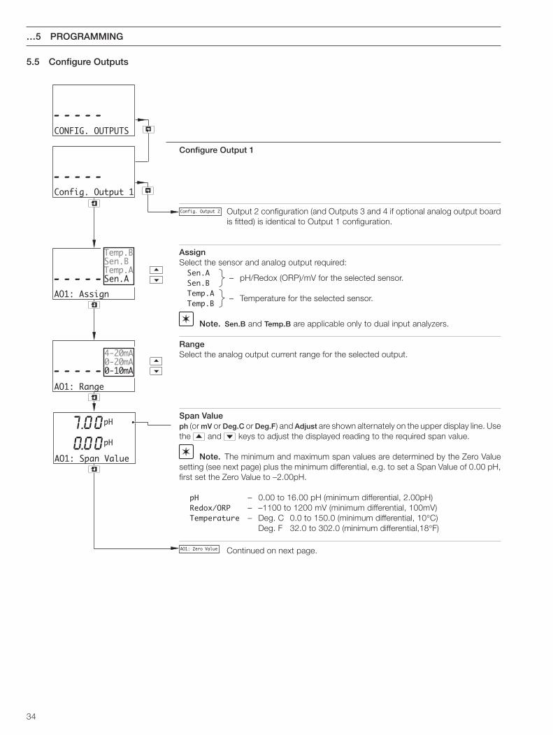
5.5 Configure Outputs
Configure Output 1
Output 2 configuration (and Outputs 3 and 4 if optional analog output boardis fitted) is identical to Output 1 configuration.
AssignSelect the sensor and analog output required:Sen.A
– pH/Redox (ORP)/mV for the selected sensor.Sen.B
Temp.A– Temperature for the selected sensor.
Temp.B
Note. Sen.B and Temp.B are applicable only to dual input analyzers.
RangeSelect the analog output current range for the selected output.
Span Valueph (or mV or Deg.C or Deg.F) and Adjust are shown alternately on the upper display line. Usethe and keys to adjust the displayed reading to the required span value.
Note. The minimum and maximum span values are determined by the Zero Valuesetting (see next page) plus the minimum differential, e.g. to set a Span Value of 0.00 pH,first set the Zero Value to –2.00pH.
pH – 0.00 to 16.00 pH (minimum differential, 2.00pH)Redox/ORP – –1100 to 1200 mV (minimum differential, 100mV)Temperature – Deg. C 0.0 to 150.0 (minimum differential, 10°C)
Deg. F 32.0 to 302.0 (minimum differential,18°F)
Continued on next page.
Config. Output 1
-----
AO1: Assign
-----
AO1: Range
-----
CONFIG. OUTPUTS
-----
Temp.BSen.BTemp.ASen.A
4-20mA0-20mA0-10mA
AO1: Zero Value
Config. Output 2
AO1: Span Value
7.00pH
0.00pH

35
5 PROGRAMMING…
…5.5 Configure Outputs
Zero Value
ph (or mV or Deg.C or Deg.F) and Adjust are shown alternately on the center display line.Use the and keys to adjust the displayed reading to the required zero value:
Note. The zero value setting plus the minimum differential determines the minimumand maximum values for the span setting, e.g. to set a span value of –1100mV, first set thezero value to –1200mV.
pH – –2.00 to 14.00 pH (minimum differential, 2.00pH)ORP/Redox – –1200 to 1100 mV (minimum differential, 100mV)Temperature – Deg. C –10.0 to 140.0 (minimum differential, 10°C)
Deg. F 14.0 to 284.0 (minimum differential, 18°F)
Default OutputSelect the system reaction to failure:Hold – Hold the analog output at the value prior to the failure.On – Stop on failure. This drives the analog output to the level set in the Default Val
frame below.Off – Ignore failure and continue operation.
Output 2 configuration.
Optional analog output board fitted – see Section 5.6.Optional analog output board not fitted – see Section 5.7.
Default Output set to Hold or Off.Default Output set to On – continued below.
Default ValueThe level to which the analog output is driven if a failure occurs.
Set the value between 0.00 and 22.00mA
Output 2 configuration.
Optional analog output board fitted – see Section 5.6.Optional analog output board not fitted – see Section 5.7.
AO1: Zero Value
7.00pH
0.0pH
AO1: Default
-----mA
HoldOnOff
AO1: Default Val
12.00mA
CONFIG. CLOCK
Config. Output 2
CONFIG. SECURITY
Config. Output 2
CONFIG. CLOCK
CONFIG. SECURITY
Config. Output 2
AO1: Default Val
Config. Output 1

36
…5 PROGRAMMING
5.6 Configure Clock
Note. The Config. Clock function is available only if the optional analog output board is fitted.
Set ClockSet the system clock.
Return to main menu.
Modbus option board fitted – see Supplementary Manual IM/AX400–MOD.Modbus option board not fitted – see Section 5.7.
FormatSelect the required clock format.
DateSet the date in the form dd:mm:yy.
Press to move between the day, month and year fields.Use the and keys to adjust each field.
TimeSet the time in the form hh:mm.
Press to move between hours and minute fields.Use the and keys to adjust each field.
Press to Set and Press to Abort are shown alternately on the lower display line.
Press the appropriate key to set the clock or abort the changes.
Set Clock?
-----
Date 01:01:01
-----Day
Time 12:00
Set
-----
CONFIG. CLOCK
-----
-----
Format
-----
Press To SetPress To Abort
Set
Hours
CONFIG. COMMS
CONFIG. CLOCK
CONFIG. SECURITY
Set Clock?
mm:dd:yydd:mm:yy

37
5 PROGRAMMING…
Alter Security CodeSet the security code to a value between 0000 and 19999.
Alter Calibration CodeSet the sensor calibration access code to a value between 0000 and 19999.
Return to main menu.
See Section 5.8.
5.7 Configure Security
5.8 Configure Logbook
Configure LogbookUse the and keys to to set the logbook On or Off.If Off is selected, all data entries in the logbook are cleared.
Return to main menu.
See Section 5.9.
Logbook
-----
CONFIG. LOGBOOK
-----
TEST/MAINTENANCE
CONFIG. LOGBOOK
OffOn
Alter Sec. Code
0000
Alter Cal. Code
0000
CONFIG. SECURITY
-----
CONFIG. LOGBOOK
CONFIG. SECURITYAlter Sec. Code

38
…5 PROGRAMMING
5.9 Test Outputs and Maintenance
Test OutputsDisplays the output test details for the four channels. Test Output 1 only is shown; theremaining outputs are identical.
Note. Outputs 3 and 4 are available only if the optional analog output board is fitted.
See below.
Test Output 1The theoretical output current value.
Output current as a percentage of the full range current.
Use the and keys to adjust the displayed theoretical output current value to give theoutput required.
See Section 7.3.
Test remaining outputs.
Maintenance
Hold OutputsEnables the relay action and analog outputs to be maintained.
Auto. – Hold is released automatically after six hours.On – Changes in relay action and analog outputs are inhibited.Off – Changes in relay action and analog outputs are not inhibited.
Note. The LEDs flash while the analyzer is in Hold mode.
Return to main menu.
See Section 7.3.
Test Outputs
-----
TEST/MAINTENANCE
-----
Test Output 1
4.00mA
20.0%
Maintenance
-----
Hold Outputs
-----Auto.OnOff
FACTORY SETTINGS
Test Output 2
CONFIG. SENSORS
TEST/MAINTENANCEMaintenance
Maintenance

39
6.1 Siting Requirements
Caution.
• Mount in a location free from excessive vibration.
• Mount away from harmful vapours and/or drippingfluids.
Information. It is preferable to mount the analyzer ateye level, allowing an unrestricted view of the front paneldisplays and controls.
Fig. 6.1 Siting Requirements
C – Within Environmental Limits
B – Within Temperature Limits
A – Maximum Distance Between Analyzer and Electrode
ElectrodeMaximum Distance100m (275 ft)
65°CMax.
–20°CMin.
IP66NEMA 4X
6 INSTALLATION

40
…6 INSTALLATION17
5 (6
.9)
150
(5.9
)
25
210 (8.23)
192 (7.56)
96 (3.76)R10 (0.4)
192
(7.5
6)
Ø6.50
(0.2
6)
94 (3.7)Dimensions in mm (in.)
Fig. 6.2 Overall Dimensions
B – Pipe-mounting
Position 'U' bolts on pipe
Position plate over 'U' bolts
Secure transmitter to mounting plate
Secure plate
A – Wall-mounting
Mark fixing centres(see Fig. 6.2)
Drill suitableholes
Secure instrument towall using
suitable fixings
1
2
3
4
1
2
3
61 (23/8) ODVertical orHorizontalPost
Fig. 6.3 Wall-/Pipe-mounting
6.2 Mounting
6.2.1 Wall-/Pipe-mount Analyzers – Figs. 6.2 and 6.3

41
6 INSTALLATION…
Fig. 6.4 Overall Dimensions
Dimensions in mm (in.)
96 (3.78)
96 (3
.78)
5.40 (0.2)91
.60
(3.6
)
137.50 (5.41)25
(0.98)
Panel Cut-out
+0.8–092 (3.62 )+0.03
–0
+0.8–092
(3.62 )+0.03–0
Insert the instrumentinto the panel cut-out.
Refit the panel clamps to the case, ensuring that thepanel clamp anchors are located correctly in their slots.
Secure the analyzer by tightening thepanel clamp retaining screws.
Loosen theretaining screw oneach panel clamp.
Remove the panel clamp andanchors from the instrument
case.
Cut a hole in the panel (see Fig. 6.4 for dimensions).Instruments may be close stacked to DIN 43835.
1
2
3
4
5
6
Fig. 6.5 Panel-mounting
…6.2 Mounting
6.2.2 Panel-mount Analyzers – Figs. 6.4 and 6.5
Caution. The clamp must fit flat on the analyzercasing. If the clamp is bowed, the securing screw isovertight and sealing problems may occur.

42
6.3 Connections, General
Warning. The power supply earth (ground) must be connected to ensure safety to personnel, reduction of the effects ofRFI interference and correct operation of the power supply interference filter.
Information.
• Earthing (grounding) – a case earth (ground) stud is fitted to the analyzer case for bus-bar earth (ground) connection – seeFig. 6.8 (wall-/pipe-mount analyzers) or Fig. 6.10 (panel-mount analyzers).
• Cable routing – always route signal output/pH electrode cable leads and mains-carrying/relay cables separately, ideally inearthed metal conduit. Use twisted pair output leads or screened cable with the screen connected to the case earth (ground)stud.
Ensure that the cables enter the analyzer through the glands nearest the appropriate screw terminals and are short and direct.Do not tuck excess cable into the terminal compartment.
• Cable glands & conduit fittings – ensure that the NEMA4X/IP66 rating is not compromised when using cable glands, conduitfittings and blanking plugs/bungs (M20 holes). The M20 glands accept cable of between 5 and 9mm (0.2 and 0.35 in.) diameter.
• Relays – the relay contacts are voltage-free and must be appropriately connected in series with the power supply and thealarm/control device which they are to actuate. Ensure that the contact rating is not exceeded. Refer also to Section 6.3.1 forrelay contact protection details when the relays are to be used for switching loads.
• Analog output – Do not exceed the maximum load specification for the selected analog output range.
Since the analog output is isolated, the –ve terminal must be connected to earth (ground) if connecting to the isolated inputof another device.
…6 INSTALLATION

43
6 INSTALLATION…
…6.3 Connections, General
6.3.1 Relay Contact Protection and Interference Suppression – Fig. 6.6If the relays are used to switch loads on and off, the relay contacts can become eroded due to arcing. Arcing also generates radiofrequency interference (RFI) which can result in analyzer malfunctions and incorrect readings. To minimize the effects of RFI, arcsuppression components are required; resistor/capacitor networks for a.c. applications or diodes for d.c. applications. Thesecomponents can be connected either across the load or directly across the relay contacts. The RFI components must be fitted to therelay terminal block along with the supply and load wires – see Fig 6.6.
For AC applications the value of the resistor/capacitor network depends on the load current and inductance that is switched. Initially,fit a 100R/0.022µF RC suppressor unit (part no. B9303) as shown in Fig. 6.6A. If the analyzer malfunctions (locks up, display goesblank, resets etc.) the value of the RC network is too low for suppression and an alternative value must be used. If the correct valuecannot be obtained, contact the manufacturer of the switched device for details on the RC unit required.
For DC applications fit a diode as shown in Fig. 6.6B. For general applications use an IN5406 type (600V peak inverse voltage at 3A– part no. B7363).
Note. For reliable switching the minimum voltage must be greater than 12V and the minimum current greater than 100mA.
Fig. 6.6 Relay Contact Protection
NC C NO
ExternalDC Supply
+ –
Relay Contacts
Load
Diode
NC C NO
ExternalAC Supply
L N
Relay Contacts
CR
Load
A – AC Applications B – DC Applications

44
…6 INSTALLATION
5
Place the blade of a small, flat bladed screwdriverinto the knockout groove and tap thescrewdriver smartly to remove the knockout
Smooth the edges of the holewith a small round or half round file.
Fit an 'O' ring seal to the the cable gland
Insert the cable gland into the holein the analyzer case from the outside
Secure the cable glandwith the securing nut
2
3
4
6
Cable entry knockoutsFactory-fitted cable gland
1 Release the captivescrews and removethe terminal cover plate
Fig. 6.7 Cable Entry Knockouts, Wall-/Pipe-mount Analyzer
…6.3 Connections, General
6.3.2 Cable Entry Knockouts, Wall-/Pipe-mount Analyzer – Fig. 6.7The analyzer is supplied with 7 cable glands, one fitted and six to be fitted, as required, by the user – see Fig. 6.7.
Caution. When removing knockouts,take great care not to damage wiring andcomponents within the analyzer.

45
6 INSTALLATION…
Warning. Before making any connections, ensure that the power supply, any high voltage-operated control circuits andhigh common mode voltages are switched off.
6.4 Wall-/Pipe-mount Analyzer Connections
6.4.1 Access to Terminals – Fig. 6.8
Fig. 6.8 Access to Terminals, Wall-/Pipe-mount Analyzer
Release CaptiveScrews and RemoveTerminal Cover Plate
Terminal Block A Terminal Block B
Terminal Block C(Analog Option Board)
Case Earth(Ground) Stud

46
Terminal block A
Terminal Block B
Terminal Block C(Analog Option Board)
C1
C2
C3
C4
C5
C6
Ear
th (G
roun
d)
C7
C
C8
NC
Rel
ay 4
C9
NO
C10
C
C11
NC
Rel
ay 5
C12
NO
C13
+A
nalo
g O
utpu
t 3C
14—
C15
+A
nalo
g O
utpu
t 4C
16—
Temperature CompensatorConnections
Line
L
Neu
tral
N
Ear
th (G
roun
d)E
CA
4
Rel
ay 1
NC
A5
NO
A6
CA
7
Rel
ay 2
NC
A8
NO
A9
CA
10
Rel
ay 3
NC
A11
NO
A12
Ana
log
Out
put 1
+A
13
—A
14
Ana
log
Out
put 2
+A
15
—A
16
B16
B15
B14
B13
B12
B11
B10 B9
B8
B7
B6
B5
B4
B3
B2
B1
TC Third
Lea
d
Com
mon
TC Third
Lea
d
Com
mon
Temperature CompensatorConnections
* If fitted** When a 2-wire Pt100, Pt1000 or 'Balco 3K' temperature compensator is fitted.*** Solution Earth also referred to as Ground Rod.TC = Temperature Compensator.
Terminal Block B pH/Redox (ORP)without solution earth
(standard input)Sensor B Sensor A
1 9 TC Common*, Link 1 & 2/9 & 10**
2 10 TC Third Lead*
3 11 TC
4 12 N/A
5 13
Reference Electrode6 14
Screen*7 15
Not Used
8 16 Glass/Metal Electrode
TC Common*, Link 1 & 2/9 & 10**
pH/Redox (ORP)with solution earth(differential input)
TC Third Lead*
TC
Screen*
Not Used
Reference Electrode
Glass/Metal Electrode
Solution Earth***
…6 INSTALLATION
…6.4 Wall-/Pipe-mount Analyzer Connections
6.4.2 Connections – Fig. 6.9
Note. Relay 3 can be configured to control the wash facility – see Section 5.4.
Fig. 6.9 Connections, Wall-/Pipe-mount Analyzer

47
6 INSTALLATION…
Warning. Before making any connections, ensure that the power supply, any high voltage-operated control circuits andhigh common mode voltages are switched off.
6.5 Panel-mount Analyzer Connections
6.5.1 Access to Terminals – Fig. 6.10
Terminal Block C(Analog Option Board) Terminal Block B
Terminal Block A
Case Earth (Ground) Stud
Fig. 6.10 Access to Terminals, Panel-mount Analyzers

48
…6 INSTALLATION
…6.5 Panel-mount Analyzer Connections
6.5.2 Connections – Fig. 6.11
Fig. 6.11 Connections, Panel-mount Analyzers
Terminal block A
L Line
N Neutral
E Earth (Ground)
A4 C
A5 NC Relay 1
A6 NO
A7 C
A8 NC Relay 2
A9 NO
A10 C
A11 NC Relay 3
A12 NO
A13 +Analog Output 1
A14 —
A15 +Analog Output 2
A16 —
Terminal Block C(Analog Option Board)
C1
C2
C3
C4
C5
C6 Earth (Ground)
C7 C
C8 NC Relay 4
C9 NO
C10 C
C11 NC Relay 5
C12 NO
C13 +Analog Output 3
C14 —
C15 +Analog Output 4
C16 —
Temperature CompensatorConnections
Terminal Block B
Common
Third Lead
TC
B1
B2
B3
B4
B5
B6
B7
B8
B9
B10
B11
B12
B13
B14
B15
B16
Common
Third Lead
TC
Temperature CompensatorConnections
Terminal Block B
Sensor B* Sensor A
1 9
2 10
3 11
4 12
5 13
6 14
7 15
8 16
TC Common*, Link 1 & 2/9 & 10** TC Common*, Link 1 & 2/9 & 10**
pH/Redox (ORP)without solution earth
(standard input)
pH/Redox (ORP)with solution earth(differential input)
TC Third Lead* TC Third Lead*
TC
N/A
TC
Reference Electrode
Reference Electrode
Not Used Not Used
Solution Earth***
Screen*
Glass/Metal Electrode
Screen*
Glass/Metal Electrode
* If fitted** When a 2-wire Pt100, Pt1000 or 'Balco 3K' temperature compensator is fitted.*** Solution Earth also referred to as Ground Rod.TC = Temperature Compensator.
Note. Relay 3 can be configured to control the wash facility – see Section 5.4.

49
Notes.• The analyzer is calibrated by the Company prior to dispatch and routine recalibration is not necessary. High stability
components are used in the analyzer's input circuitry and, once calibrated, the Analog to Digital converter chip self-compensates for zero and span drift. It is therefore unlikely that the calibration will change over time. It is not advisable toattempt recalibration unless the input board has been replaced or the calibration tampered with.
• Prior to attempting recalibration, test the analyzer's accuracy using suitably calibrated test equipment – see Sections 7.2 and7.3.
7.1 Equipment Requireda) Millivolt source (pH or Redox input simulator): –1000 to 1000 mV.
b) Decade resistance box (Pt100/Pt1000 temperature input simulator): 0 to 1kΩ (in increments of 0.01Ω), accuracy ±0.1%.
c) Digital milliammeter (current output measurement): 0 to 20mA.
Note. Resistance boxes have an inherent residual resistance which may range from a few mΩ up to 1Ω. This value mustbe taken into account when simulating input levels, as should the overall tolerance of the resistors within the boxes.
7.2 Preparationa) Switch off the supply and disconnect the electrode system, temperature compensator(s) and current output(s) from the analyzer's
terminal blocks.
b) Sensor A:1) Link terminals B9 and B10.2) Connect the millivolt source to terminals B16 (+ve) and B14 (–ve) to simulate the pH or Redox input. Connect the millivolt
source earth to the Case Earth (Ground) Stud – see Fig. 6.8 (wall-/pipe-mount analyzer) or Fig. 6.10 (panel-mount analyzer).4) Connect the 0 to 10kΩ decade resistance box to terminals B11 and B9 to simulate the Pt100/Pt1000/Balco 3K.
Sensor B:1) Link terminals B1 and B2.2) Connect the millivolt source to terminals B8 (+ve) and B6 (–ve) to simulate the pH or Redox input. Connect the millivolt source
earth to the Case Earth (Ground) Stud – see Fig. 6.8 or (wall-/pipe-mount analyzer) or Fig. 6.10 (panel-mount analyzer).4) Connect the 0 to 10kΩ decade resistance box to terminals B3 and B1 to simulate the Pt100/Pt1000/Balco 3K.
c) Connect the milliammeter to the analog output terminals.
d) Switch on the supply and allow ten minutes for the circuits to stabilize.
d) Select the FACTORY SETTINGS page and carry out Section 7.3.
Fig. 7.1 Analyzer Terminal Links and Decade Resistance Box Connections
Terminal link
pH/RedoxInput Simulator
TemperatureSimulator
B10 B11 B12 B13 B14B9Sensor A Terminal Numbers
Sensor B Terminal Numbers B2 B3 B4 B5 B6B1
B15 B16
B7 B8
–ve +ve
7 CALIBRATION

50
…7 CALIBRATION
7.3 Factory Settings
FACTORY SETTINGS Factory Set Code Cal. Sensor A
A:mV Zero (-1V)
A:mV Span (+1V)
A:T.Zero (100R)
A:T.Span (150R)
Cal. Sensor B
B:T.Zero (100R)
B:T.Span (150R)
Cal. Output 1
O1: Adjust 4mA
O1: Adjust 20mA
To OPERATING PAGE
A:T.Zero (1K0) B:T.Zero (1K0)
A:T.Span (1K5) B:T.Span (1K5)
Available only if theanalog option board is fitted
Key
Load/Save Config
Factory Config.
User Config.
Alter Fact.CodeCal. Output 3 Cal. Output 4
O3: Adjust 4mA O4: Adjust 4mA
O3: Adjust 20mA O4: Adjust 20mA
Press To AbortPress To Set
Cal. Output 2
O2: Adjust 4mA
O2: Adjust 20mA
Use the Sidescroll Key to scroll through the Pages within each Menu
Use the MenuKey to scroll
throughthe Menus
Use the DownscrollKey to scroll through
the Parameterswithin each Page
Section 7.3, Page 51
A:T.Span (5K0)
A:T.Zero (2K0)
B:mV Span (+1V)
B:T.Zero (2K0)
B:T.Span (5K0)
B:mV Zero (-1V)
Dual input analyzer only
Fig. 7.2 Overall Factory Settings Chart

51
7 CALIBRATION…
…7.3 Factory Settings
Factory Settings Access CodeEnter the required code number, between 0000 and 19999, to gain access to the factorysettings. If an incorrect value is entered, access to subsequent parameters is preventedand the display reverts to the top of the Factory Settings Page.
Calibrate Sensor A
Note. The values in the display lines for sensor calibration are shown only asexamples – the actual values obtained will differ.
Sensor B calibration (dual input analyzers only) is identical to Sensor Acalibration.
See page 53.
Return to Operating Page – see Section 2.3.
Millivolt ZeroSet the millivolt source to –1000mV.
The display advances automatically to the next step once a stable and valid value isrecorded.
Note. The upper 6-segment display shows the measured input voltage. Once thesignal is within range the lower 6-segment display shows the same value and Calib isdisplayed to indicate that calibration is in progress.
Millivolt SpanSet the millivolt source to +1000mV
The display advances automatically to the next step once a stable and valid value isrecorded.
Temperature Zero (100R)Set the temperature simulator to 100Ω
The display advances automatically to the next step once a stable and valid value isrecorded.
Temperature Span (150R)Set the temperature simulator to 150Ω
The display advances automatically to the next step once a stable and valid value isrecorded.
Continued on next page.
Factory Set Code
0000
FACTORY SETTINGS
-----
Cal. Sensor A
-----
A:mV Zero (-1V)
0.256Calib
A:mV Span (+1V)
Volts
Calib
A:T.Zero (100R)
Volts
Calib
Cal. Sensor B
Monitoring pH
0.256Volts
A:T.Span (150R)
Volts
Calib
A: T.Zero (1K0)
2.2462.246
0.8000.800
1.1871.187
Cal. Output 1

52
…7 CALIBRATION
Temperature Zero (1k0)Set the temperature simulator to 1000Ω
The display advances automatically to the next step once a stable and valid value isrecorded.
Temperature Span (1k5)Set the temperature simulator to 1500Ω
The display advances automatically to the next step once a stable and valid value isrecorded.
Temperature Zero (2k0)Set the temperature simulator to 2000Ω
The display advances automatically to the next step once a stable and valid value isrecorded.
Temperature Span (5k0)Set the temperature simulator to 5000Ω
The display returns automatically to Cal. Sensor A once a stable and valid value is recorded.
…7.3 Factory Settings
A:T.Span (5K0)
A:T.Zero (2K0)
0.4160.416
Volts
Calib
0.8310.831
Volts
Calib
A:T.Span (1K5)
0.6510.651
Volts
Calib
Cal. Sensor A
A:T.Zero (1K0)
0.4540.454
Volts
Calib

53
Calibrate Output 1
Note. When adjusting the 4 and 20mA outputs, the display reading is unimportantand is used only to indicate that the output is changing when the and keys arepressed.
See below.
Adjust 4mAUse the and keys to set the milliammeter reading to 4mA.
Note. The analog output range selected in Configure Outputs (see Section 5.5) doesnot affect the reading.
Adjust 20mAUse the and keys to set the milliammeter reading to 20mA.
Note. The analog output range selected in Configure Outputs (see Section 5.5) doesnot affect the reading.
See below.
Operating Page – see Section 2.3.
Calibrate Output 2
Note. Output 2 calibration (and Outputs 3 and 4 if optional analog output board isfitted) is identical to Output 1 calibration.
Optional analog output board fitted.Optional analog output board not fitted – continued on next page.
Optional analog output board fitted.Optional analog output board not fitted – continued on next page.
Operating Page – see Section 2.3.
Cal. Output 1
-----
O1: Adjust 4mA
16000
O1: Adjust 20mA
7200
Monitoring pH
Cal. Output 2
Cal. Output 1
Cal. Output 2
Cal. Output 2
-----
O1: Adjust 20mA
7200
Monitoring pH
Cal. Output 3
Cal. Output 2
Cal. Output 3
Load/Save Config
Load/Save Config
…7.3 Factory Settings
7 CALIBRATION…

54
…7 CALIBRATION
Load/Save Config-----
YesNo
Alter Fact. Code
0000
-----Press To Set.Press To Abort
Monitoring pH
Alter Fact. Code
FACTORY SETTINGS
Monitoring pH
User Config.Factory Config.
-----LoadSave
User Config.
Load/Save Config
Load/Save ConfigurationSelect whether a configuration is to be loaded or saved.
Note. If No is selected, pressing the key has no effect.
See below.
Operating Page – see Section 2.3.
Yes selected – continued below.
Load User/Factory Configuration
Note. Applicable only if Load/Save Config. is set to Yes.
Factory Config. – resets all the parameters in the Configuration Pages to theCompany Standard.
Save User Config. – saves the current configuration into memory.Load User Config. – reads a saved user configuration into memory.
User Config. and Factory Config. are displayed alternately if a User Configuration has beensaved previously. Use the and keys to make the required selection.
Note. User Config. is displayed only if a User Configuration has been savedpreviously.
Press to Set and Press to Abort are displayed alternately on the lower display line.
Press the appropriate key to load/save the configuration or abort the changes.
Alter Factory CodeSet the factory settings access code to a value between 0000 and 19999.
Return to main menu.
Operating Page – see Section 2.3.
…7.3 Factory Settings

55
egasseMrorrE esuaCelbissoP
001TPYTLUAF:A0001TPYTLUAF:A
OCLABYTLUAF:A
detaicossa/rotasnepmocerutarepmeTneporehtieeraArosneSrofsnoitcennoc
.tiucrictrohsrotiucric
001TPYTLUAF:B0001TPYTLUAF:B
OCLABYTLUAF:B
detaicossa/rotasnepmocerutarepmeTneporehtieeraBrosneSrofsnoitcennoc
.tiucrictrohsrotiucric
EPOLSWOLLAC:AEPOLSWOLLAC:B
eht,deliaftonsahnoitarbilacehthguohtlArosnesehthtiwdetaicossariapedortcele
dnadeugitafgnimocebsidetacidni.dednemmocersitnemecalper
DELIAFLACHP:ADELIAFLACHP:B
sahdetacidnirosnesehtfonoitarbilacehTtaeperdnaseulavreffubkcehC.deliaf
ehtecalper,stsisreptluafehtfI.gnireffub.sedortcele
DETIBIHNIHSAW
noitcnuFhsaW ottessi ffO ehtni gnitarepOegaP . teS noitcnuFhsaW ot nO noitceSees–
.3.3.2
8 SIMPLE FAULT FINDING
8.1 Error MessagesIf erroneous or unexpected results are obtained the fault may beindicated by an error message – see Table 8.1. However, somefaults may cause problems with analyzer calibration or givediscrepancies when compared with independent laboratorymeasurements.
8.2 Calibration Fail Message orno Response to pH/Redox ChangesThe majority of problems are associated with the electrodes andcabling. Replace the electrodes as an initial check – refer to theappropriate instruction manual. It is also important that allprogram parameters have been entered correctly and have notbeen altered inadvertently – see Section 7.
If the above checks do not resolve the fault:
a) Check that the analyzer responds to a millivolt input.Connect a pH simulator, such as Model 2410, to thetransmitter input; +ve to glass and –ve to reference – seeSection 6.4 or 6.5. Select the CONFIG. SENSORS page andset the Probe Type to Redox or ORP. Check that the analyzerdisplays the correct values as set on the simulator.
Note. A normal laboratory mV source is notsuitable for use as a pH simulator.
Failure to respond to the input indicates a fault with the analyzerwhich must be returned to the Company for repair. Correctresponse, but with incorrect readings, usually indicates acalibration problem. Recalibrate the analyzer as detailed inSection 7.
Table 8.2 Temperature Readings for Resistance Inputs
Table 8.1 Error Messages erutarepmeT (ecnatsiseRtupnI Ω)
Cº °F 001tP 0001tP K3oclaB
0 23 00.001 00.0001 00.3662
01 05 09.301 00.9301 00.8972
02 86 97.701 09.7701 00.3392
52 77 37.901 03.7901 00.0003
03 68 76.111 07.6111 00.8603
04 401 45.511 04.5511 00.3023
05 221 04.911 00.4911 00.8333
06 041 42.321 04.2321 00.3743
07 851 70.721 07.0721 00.8063
08 671 98.031 09.8031 00.3473
09 491 07.431 00.7431 00.8783
001 212 05.831 00.5831 00.3104
5.031 9.662 00.051 00.0051 05.2854
b) Use the pH simulator to carry out an impedance check onthe analyzer, i.e. glass to reference, glass to earth andreference to earth – refer to simulator manual.
If the analyzer fails this test, check for moisture within thetransmitter and in particular the terminal compartment. It is vitalthat all evidence of moisture is removed with the use of a hot airdrier.
c) Reconnect the electrode cable and connect the simulator tothe electrode end of the cable. Repeat the procedures a) andb) above. If the analyzer fails test b), check for moisturearound the connections and check that the insulation on theinner co-axial conductor is clean and that the graphite layerhas been removed.
8.3 Checking the Temperature InputCheck the analyzer responds to a temperature input.Disconnect the Pt100/Pt1000/Balco 3K leads and connect asuitable resistance box directly to the analyzer inputs – seeSection 6.4 (wall-/pipe-mount analyzer) or Section 6.5(panel-mount analyzer). Check the analyzer displays the correctvalues as set on the resistance box – see Table 8.2.
Incorrect readings usually indicate an electrical calibrationproblem. Re-calibrate the analyzer as detailed in Section 7.3.

56
APPENDIX A
A1 Buffer SolutionsThe pH value of buffer solutions is influenced considerably bytemperature variations. Thus, when significant temperaturefluctuations occur, it is general practice to correct automaticallythe measured, prevailing pH to the value that would apply if thesolution temperature were 25°C, the internationally acceptedstandard.
The following tables include the pH values for US Tech, NIST,DIN, Merck, and ABB buffer solutions. Standards are for 4, 7 and9pH values, from 0 to 100°C.
Table A1 ABB Buffer Solutions
Table A2 DIN Buffer Solutions
pmeT sreffuBBBA
°C °F Hp10.4 Hp7 Hp81.9
0 23 000.4 011.7 574.9
5 14 899.3 904.9
01 05 799.3 060.7 743.9
51 95 899.3 882.9
02 86 100.4 010.7 332.9
52 77 500.4 000.7 281.9
03 68 110.4 089.6 431.9
53 59 810.4 190.9
04 401 720.4 079.6 150.9
54 311 830.4 510.9
05 221 050.4 079.6 389.8
55 131 460.4 659.8
06 041 080.4 079.6 239.8
56 941 790.4 319.8
07 851 611.4 099.6 898.8
57 761 731.4 888.8
08 671 951.4 030.7 288.8
58 581 381.4 088.8
09 491 802.4 080.7 488.8
59 302 532.4 298.8
pmeT 66291NID
°C °F Hp86.1 Hp10.4 Hp68.6 Hp81.9
0 23 666.1 300.4 489.6 464.9
5 14 866.1 999.3 159.6 593.9
01 05 076.1 899.3 329.6 233.9
51 95 276.1 999.3 009.6 672.9
02 86 576.1 200.4 188.6 522.9
52 77 976.1 800.4 568.6 081.9
03 68 386.1 510.4 358.6 931.9
53 59 886.1 420.4 448.6 201.9
04 401 496.1 530.4 838.6 860.9
54 311 007.1 740.4 438.6 830.9
05 221 707.1 060.4 338.6 110.9
55 131 517.1 570.4 438.6 589.8
06 041 327.1 190.4 638.6 269.8
56 941
07 851 347.1 621.4 548.6 129.8
57 761
08 671 667.1 461.4 958.6 588.8
58 581
09 491 297.1 502.4 778.6 058.8
59 302 608.1 722.4 688.6 338.8

57
APPENDIX A…
Table A3 MERCK Buffer Solutions Table A4 NIST Buffer Solutions
…A1 Buffer Solutions
pmeT kcreM
°C °F Hp4 Hp7 Hp9 Hp01
0 23 50.4 31.7 42.9 62.01
5 14 40.4 70.7 61.9 71.01
01 05 20.4 50.7 11.9 11.01
51 95 10.4 20.7 50.9 50.01
02 86 00.4 00.7 00.9 00.01
52 77 10.4 89.6 59.8 49.9
03 68 10.4 89.6 19.8 98.9
53 59 10.4 69.6 88.8 48.9
04 401 10.4 59.6 58.8 28.9
54 311 10.4 59.6 28.8
05 221 00.4 59.6 97.8 47.9
55 131 00.4 59.6 67.8
06 041 00.4 69.6 37.8 76.9
56 941 00.4 69.6 27.8
07 851 00.4 69.6 07.8 26.9
57 761 00.4 69.6 86.8
08 671 00.4 79.6 66.8 55.9
58 581 00.4 89.6 56.8
09 491 00.4 00.7 46.8 94.9
59 302 00.4 20.7 46.8 338.8
pmeT TSIN
°C °F Hp10.4 Hp68.6 Hp81.9
0 23 300.4 289.6 064.9
5 14 899.3 949.6 293.9
01 05 699.3 129.6 133.9
51 95 699.3 898.6 672.9
02 86 999.3 878.6 722.9
52 77 400.4 368.6 381.9
03 68 110.4 158.6 341.9
53 59 020.4 248.6 701.9
04 401 030.4 638.6 470.9
54 311 240.4 238.6 440.9
05 221 550.4 138.6 710.9
55 131 070.4
06 041 580.4
56 941
07 851 021.4
57 761
08 671 061.4
58 581
09 491 091.4
59 302 012.4

58
…APPENDIX A
Table A5 US Tech Buffer Solutions
pmeT )SU(sreffuBlacinhceT
°C °F Hp10.4 Hp7 Hp10.01
0 23 000.4 811.7 713.01
5 14 899.3 780.7 542.01
01 05 799.3 950.7 971.01
51 95 899.3 630.7 811.01
02 86 100.4 610.7 260.01
52 77 500.4 000.7 210.01
03 68 110.4 789.6 669.9
53 59 810.4 779.6 529.9
04 401 720.4 079.6 988.9
54 311 830.4 569.6 758.9
05 221 050.4 469.6 828.9
55 131 460.4 569.6
06 041 080.4 869.6
56 941 790.4 479.6
07 851 611.4 289.6
57 761 731.4 299.6
08 671 951.4 400.7
58 581 381.4 810.7
09 491 802.4 430.7
59 302 532.4 250.7
…A1 Buffer Solutions

59
pH/Redox (ORP)Inputs
1 or 2* pH or mV inputs (*AX466 only) and solution earth
1 or 2* temperature sensors (*AX466 only)
Permits connection to glass or enamel pH and referencesensors and Redox (ORP) sensors
Input resistance
Glass >1 x 10¹³ΩReference 1 x 10¹³Ω
Range
–2 to 16pH or –1200 to +1200mV
Minimum span
Any 2pH span or 100mV
Resolution
0.01pH
Accuracy
0.01pH
Temperature compensation modes
Automatic or manual Nernstian compensation
Range –10 to 150°C (14 to 302°F)
Process solution compensation with configurable coefficient
Range 0 to 100°C (32 to 212°F)
Temperature sensor
Programmable Pt100, Pt1000 & Balco 3KΩ
DisplayType
Dual 5-digit, 7-segment backlit LCD
Information
16-character, single line dot-matrix
Energy-saving function
Backlit LCD configurable as ON or Auto Off after 60s
Logbook (with option board)
Electronic record of major process events and calibrationdata
Real-time clock (with option board)
Records time for logbook and auto-cleaning functions
Control Function – AX460 OnlyController Type
P, PI, PID (Configurable)
Control OutputsAnalog
Current output control (0 to 100%)
Time proportioning cycle time
5 to 60s, programmable in 1s steps displayed with doP orroP
Pulse frequency
1 to 120 pulses per minute
Controller action
Reverse, direct or bi-directional (programmable)
Proportional band
0.1 to 1000%, programmable in 0.1% increments
Integral action time (Reset)
1 to 7200s in 1s steps, 0 = Off
Derivative
0.1 to 1000s in 0.1s increments
Auto/Manual
User-programmable
SPECIFICATION

60
Sensor cleaning functionConfigurable cleaning action relay contact
Continuous
Pulse in 1s on and off times
Frequency
5 minutes to 24 hours, fully configurable
Duration
15s to 10 minutes, fully configurable
Recovery period
30s to 5 minutes, fully configurable
Electrode Calibration ModesCalibration with auto-stability checking
Automatic 1 or 2 point calibration selectable from:
ABBDINMerckNISTUS Tech2 x User-defined buffer tables
manual entry or 2-point calibrationone-point process calibration
Calibration RangesZero point
0 to 14pH
Slope
Between 40 and 105% (low limit user configurable)
Outputs and Set PointsNumber of set points
3 if relay control, 5 with option card
Number of relays
4 standard, 2 standard and 2 control
Retransmission outputs
2 (4 optional) fully-isolated standard
Environmental DataOperating temperature limits
–20 to 65°C (–4 to 149°F)
Storage temperature limits
–25 to 75°C (–13 to 167°F)
Operating humidity limits
Up to 95%RH non condensing
EMCEmissions and immunity
Meets requirements of:
EN61326 (for an industrial environment)
EN50081-2
EN50082-2
Analog RetransmissionNumber of signals
Two, fully-isolated outputs supplied as standard
Four, fully-isolated outputs when ordered with option card
Output current
0 to 10mA, 0 to 20mA or 4 to 20mA
Analog output programmable to any value between0 and 22mA to indicate system failure
Accuracy
±0.25% FSD, ±5% of reading
Resolution
0.1% at 10mA 0.05% at 20mA
Maximum load resistance
750Ω at 20mA
Configuration
Can be assigned to either measured variable oreither sample temperature
Serial communications
Modbus serial data interface
…SPECIFICATION

61
SPECIFICATION…
Relay Outputs – On/OffNumber of relays
Three, supplied as standard
Five, when ordered with option card
Set point adjustment
Fully configurable as normal or failsafe high/low ordiagnostic alert
Hysteresis of reading
Programmable 0 to 5% in 0.1% increments
Delay
Programmable 0 to 60s in 1s intervals
Relay contacts
Single-pole changeover
Rating 5A, 115/230V AC, 5A DC
Insulation
2kV RMS contacts to earth/ground
Access to FunctionsDirect keypad access
Measurement, maintenance, configuration, diagnostics orservice functions
Performed without external equipment or internal jumpers
Power supplyVoltage requirements
85 to 265V AC 50/60 Hz
24V AC or 12 to 30V DC (optional)
Power consumption
<10VA
Insulation
Mains to earth (line to ground) 2kV RMS
SafetyGeneral safety
EN61010-1
Overvoltage Class II on inputs and outputs
Pollution category 2
Cable Entry TypesStandard
5 or 7* x M20 cable glands
N. American
7 x knockouts suitable for 1/2 in. Hubble gland
Hazardous area approvalsCENELEC ATEX IIG EEx n IIC T4 Pending
FM non-incendive Class I Div. 2 Groups A to D Pending
CSA non-incendive Class I Div. 2 Groups A to DPending
Mechanical DataPanel-mount versions
IP66/NEMA4X
Dimensions 192mm high x 230mm wide x 94mm deep(7.56 in. high x 9.06 in. wide x 3.7 in. deep)
Weight 1kg (2.2 lb)
Panel-mount versions
IP66/NEMA4X (front only)
Dimensions 96mm x 96mm x 162mm deep(3.78 in. x 3.78 in. x 6.38 in. deep)
Weight 0.6kg (13.2 lb)
LanguagesLanguages configurable
English
French
German
Italian
Spanish
SS/AX4PH Issue 1

62
NOTES

63
NOTES…

64
…NOTES

PRODUCTS & CUSTOMER SUPPORT
ProductsAutomation Systems
• for the following industries:– Chemical & Pharmaceutical– Food & Beverage– Manufacturing– Metals and Minerals– Oil, Gas & Petrochemical– Pulp and Paper
Drives and Motors• AC and DC Drives, AC and DC Machines, AC motors to 1kV• Drive systems• Force Measurement• Servo Drives
Controllers & Recorders• Single and Multi-loop Controllers• Circular Chart , Strip Chart and Paperless Recorders• Paperless Recorders• Process Indicators
Flexible Automation• Industrial Robots and Robot Systems
Flow Measurement• Electromagnetic Magnetic Flowmeters• Mass Flow Meters• Turbine Flowmeters• Wedge Flow Elements
Marine Systems & Turbochargers• Electrical Systems• Marine Equipment• Offshore Retrofit and Refurbishment
Process Analytics• Process Gas Analysis• Systems Integration
Transmitters• Pressure• Temperature• Level• Interface Modules
Valves, Actuators and Positioners• Control Valves• Actuators• Positioners
Water, Gas & Industrial Analytics Instrumentation• pH, conductivity, and dissolved oxygen transmitters and sensors• ammonia, nitrate, phosphate, silica, sodium, chloride, fluoride,
dissolved oxygen and hydrazine analyzers.• Zirconia oxygen analyzers, katharometers, hydrogen purity and
purge-gas monitors, thermal conductivity.
Customer Support
We provide a comprehensive after sales service via a WorldwideService Organization. Contact one of the following offices fordetails on your nearest Service and Repair Centre.
United KingdomABB LimitedTel: +44 (0)1453 826661Fax: +44 (0)1453 827856
United States of AmericaABB Inc.Tel: +1 (0) 755 883 4366Fax: +1 (0) 755 883 4373
Client Warranty
Prior to installation, the equipment referred to in this manual mustbe stored in a clean, dry environment, in accordance with theCompany's published specification. Periodic checks must bemade on the equipment's condition.
In the event of a failure under warranty, the followingdocumentation must be provided as substantiation:
1. A listing evidencing process operation and alarm logs at time offailure.
2. Copies of operating and maintenance records relating to thealleged faulty unit.

IM/A
X4P
HIs
sue
2
The Company’s policy is one of continuous productimprovement and the right is reserved to modify the
information contained herein without notice.
Printed in UK (01.03)
© ABB 2003
ABB LimitedOldends Lane, StonehouseGloucestershire, GL10 3TAUKTel: +44 (0)1453 826661Fax: +44 (0)1453 827856
ABB Inc.2175 Lockheed WayCarson City, NV 89706USATel: +1 (0) 775 883 4366Fax: +1 (0) 775 883 4373
ABB has Sales & Customer Supportexpertise in over 100 countries worldwide
www.abb.com