Embed Size (px)
Citation preview
537
Modelling the hysteretic characteristics of amagnetorheological uid damper
En Rong Wang12 Xiao Qing Ma2 S Rakhela2 and C Y Su21Faculty of Electrical and Electronic Engineering Nanjing Normal University Nanjing Peoplersquos Republic of China2Department of Mechanical Engineering Concordia University Montreal Canada
Abstract A generalized model is proposed to characterize the biviscous hysteretic force character-istics of a magnetorheological (MR) uid damper using symmetric and asymmetric sigmoid functionson the basis of a fundamental force generation mechanism observed qualitative trends and measureddata under a wide range of control and excitation conditions Extensive laboratory measurementswere performed to characterize the hysteretic force properties of an MR damper under a wide rangeof magnitudes of control current and excitation conditions (frequency and stroke) The global modelis realized upon formulation and integration of component functions describing the preyield hysteresissaturated hysteresis loop linear rise and current-induced rise The validity of the proposed model isdemonstrated by comparing the simulation results with measured data in terms of hysteretic forcendashdisplacement and forcendashvelocity characteristics under a wide range of test conditions The resultsrevealed reasonably good agreement between the measured data and model results irrespective ofthe test conditions considered The results of the study suggest that the proposed model could bee ectively applied for characterizing the damper hysteresis and for development of an optimalcontroller for implementation in vehicular suspension applications
Keywords magnetorheological uid damper hysteresis hysteresis model force limitingexperimental forcendashvelocity characterization
NOTATION
am excitation stroke (m)
a0 positive constant associated with thehysteresis slope coe cient a
a1 positive constant adjusting the rising rateof the exponent vm [(ms) Otilde 1 ]
a2 positive constant associated with thecontrol current gain c
i(A Otilde 1)
a3 positive constant associated with thezero-force velocity intercept vh (A Otilde 1)
a4 positive constant associated with thelinear rise coe cient k
v[(ms) Otilde 1 ]
ce
ce(
vm ) excitation condition gain
ci c
i(i ) control current gain
cv(v) high-velocity damping coe cient
ER electrorheologicalf instantaneous force (N)f (v+vh) force in a general hysteresis loop (N)
The MS was received on 3 May 2002 and was accepted after revisionfor publication on 7 February 2003 Corresponding author Department of Mechanical EngineeringConcordia University 1455 de Maisonneuve Blvd West MontrealQuebec Canada H3G 1M8
D05302 copy IMechE 2003 Proc Instn Mech Engrs Vol 217 Part D J Automobile Engineering
fh zero-velocity force intercept (N)
fm maximum force developed by the
damper (N)fs(v+vh) force in a saturated hysteresis loop in the
absence of a linear rise (N)ft transition force (N)f0 seal friction force (N)
i current (A)I0 arbitrary constant associated with the
control current gain ci
(A)I1 arbitrary constant associated with the
zero-force velocity intercept vh (A)kv
linear rise coe cientk0 positive constant associated with the
hysteresis slope coe cient ak1 positive constant associated with the
linear rise coe ceint kv
k2 positive constant associated with the
control current gain ci
k3 k4 positive constant associated with thezero-force velocity intercept vh
MR magnetorheologicalv xb instantaneous piston velocity (ms)vh zero-force velocity intercept (ms)
538 EN RONG WANG XIAO QING MA S RAKHELA AND C Y SU
vm maximum velocity of the damper piston(ms)
vt transition velocity (ms)x instantaneous piston displacement (m)x dvdt instantaneous piston acceleration (ms2)
a hysteresis slope coe cientb
h high-velocity slope (N sm)bl low-velocity slope (N sm)v excitation frequency (rads)
1 INTRODUCTION
A wide range of magnetorheological (MR) uid-baseddampers are currently being explored for their potentialimplementation in various systems such as vibrationcontrol devices and vehicle suspension A number ofanalytical and experimental studies have clearly estab-lished superior potential performance bene ts of MRdampers in vehicle applications in relation to conven-tional hydraulic dampers [1ndash3 ] The MR dampers o erhigh viscous damping corresponding to low velocities inthe preyield condition while the post-yield saturationcorresponding to high velocities can be characterized bya considerably lower viscous damping coe cient Therequirement of adequate ride road-holding handlingand directional control stability performance of roadvehicles entails variable damping [4 ] which could beachieved with MR dampers with only minimal powerconsumption The MR damper is considered to be acontinuously controlled semi-active damper since ito ers only variable damping force with minimal powerrequirement unlike a fully active suspension which couldadd or remove energy depending upon the demand withthe help of an elaborate power supply The semi-activelycontrolled MR uid dampers o er rapid variation indamping properties in a reliable fail-safe manner sincethey continue to provide adequate damping in a passivemanner in the event of a control hardware malfunction[5 ] Although a vast number of semi-active variabledamping concepts based upon hydraulic ow modu-lation and electrorheological (ER) uids have beendeveloped clear advantages of the MR uid dampershave been established such as signi cantly higher yieldstress and a wider operating temperature range [5ndash7 ]
Owing to the rheology of the MR uid in terms of itsshear stressndashstrain rate behaviour the damper exhibitshighly non-linear variations in damping force attributedto the hysteresis and force-limiting properties of the uidas functions of the intensity of the applied magnetic eldand displacement and velocity of the piston The devel-opment of an e ective controller for realizing desirablevariations in damping requires accurate characterizationof the hysteretic forcendashvelocity characteristics of the MRdamper in the preyield condition and force saturationin the post-yield condition In view of the highly non-
D05302 copy IMechE 2003Proc Instn Mech Engrs Vol 217 Part D J Automobile Engineering
linear properties of MR dampers considerable attemptsare being made to study their dynamic behaviour formodel synthesis and for developing e ective controlalgorithms [5ndash9 ] Dyke et al [10] proposed a dampermodel on the basis of the BoucndashWen hysteresis modelThe model however poses inherent di culties in pre-dicting essential parameters and in realizing control sys-tems for desired tracking control performance TheBingham plastic model which has been proposedassumes rigid material behaviour in the preyield whilethe shear ow in the post-yield is characterized by aviscous damping coe cient [7 ] Assuming the materialto be plastic in both pre- and post-yield conditionsStanway et al [11] proposed a non-linear model wherethe preyield force is characterized by a considerably highviscous damping On the basis of this model Wereleyet al [7 ] proposed a non-linear hysteretic bilinear modelby tting the forcendashvelocity characteristics using fourparameters pre- and post-yield viscous dampingcoe cients yield force and zero-force velocity interceptThe above models however do not include the e ectsof continually varying control current Moreover thehysteretic damping force generated by an MR damperdepends not only upon the intensity of the magnetic eldbut also upon the excitation frequency and amplitude ofthe damper motion This dependence of the hystereticforce on the nature of excitation has not yet beenaccurately characterized
In this study a series of laboratory tests have beenperformed to characterize the dependence of the hyster-etic damping force of an MR damper on the excitationfrequency and stroke and the control current The meas-ured data are used to synthesize a generalized model ofthe MR damper on the basis of a symmetric sigmoidfunction The e ectiveness of the proposed hystereticmodel is demonstrated by comparing the simulationresults with the measured data over a wide range ofexcitation parameters and magnitudes of control cur-rent The proposed model could thus be used for controlalgorithm development and for assessment of thevibration attenuation performance of a semi-activelycontrolled MR damper
2 TEST METHODOLOGY
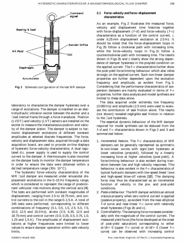
An MR damper schematically shown in Fig 1 is con-sidered for modelling of its hysteretic forcendashvelocitycharacteristics The damper consists of a nitrogen-charged accumulator and two MR uid chambers separ-ated by a piston with ori ces and coils The variationsin viscous and shear properties of the uid caused bythe applied magnetic eld cause variations in the damp-ing force A dc current limited to 2 A serves as thecommand signal as well as the input for the coils
The forcendashvelocity and forcendashdisplacement charac-teristics of the test MR damper are measured in the
539HYSTERETIC CHARACTERISTICS OF A MAGNETORHEOLOGICAL FLUID DAMPER
Fig 1 Schematic con guration of the test MR damper
laboratory to characterize the damper hysteresis over arange of excitations The damper is installed on an elec-trohydraulic vibration exciter between the exciter and a xed inertial frame through a force transducer Position(LVDT) and velocity (LVT) sensors are installed on theexciter to measure the instantaneous position and veloc-ity of the damper piston The damper is subject to har-monic displacement excitations of di erent constantamplitudes at selected discrete frequencies The forcevelocity and displacement data acquired through a dataacquisition board are used to provide on-line displaysof hysteretic forcendashvelocity characteristics A dual regu-lated dc power supply is used to supply the controlcurrent to the damper A thermocouple is also mountedon the damper body to monitor the damper temperaturein order to ensure the data were obtained within ade ned temperature range (30plusmn10 degC)
The hysteretic forcendashvelocity characteristics of theMR uid damper are measured under sinusoidal dis-placement excitations in the 0ndash15 Hz frequency rangewhich is considered to represent the range of predomi-nant vehicular ride motions along the vertical axis [4 ]The tests are performed with constant magnitudes ofdisplacement ranging from 25 to 1875 mm and con-trol currents to the coil in the range 0ndash15 A A total of245 tests were performed corresponding to di erentcombinations of frequency (01 05 15 25 50 75100 125 and 150 Hz) stroke (25 635 125 and1875 mm) and control current (00 025 05 075 10125 and 15 A) The amplitudes of displacement exci-tations at higher frequencies were limited to lowervalues to ensure damper operation within safe velocitylimits
D05302 copy IMechE 2003 Proc Instn Mech Engrs Vol 217 Part D J Automobile Engineering
21 Forcendashvelocity and forcendashdisplacementcharacteristics
As an example Fig 2 illustrates the measured forcevelocity and displacement time histories togetherwith forcendashdisplacement ( fndashd ) and forcendashvelocity ( fndashv)characteristics as a function of the control current iunder 625 mm displacement excitation at 25 Hz Itshould be noted that the forcendashdisplacement loops inFig 2b follow a clockwise path with increasing timewhile the forcendashvelocity loops in Fig 2c follow acounterclockwise path with increasing time The resultsshown in Figs 2b and c clearly show the strong depen-dence of damper hysteresis in the preyield condition onthe applied current The fndashv characteristics further showthe post-yield force-limiting behaviour which also reliesstrongly on the applied current Such non-linear damperproperties are further dependent upon the excitationfrequency and amplitude as evident from Fig 3Considering that the performance characteristics of sus-pension dampers are mainly evaluated in terms of fndashv
properties further data analysis and model synthesis arelimited to these data alone
The data acquired under extremely low frequency(0083 Hz) and amplitude (25 mm) were used to evalu-ate the contribution of seal friction alone The results(not shown) revealed negligible seal friction in relationto the uid hysteresis
The essential dynamic behaviour of the MR damperrequired for model synthesis can be deduced from thefndashd and fndashv characteristics shown in Figs 2 and 3 andsummarized below
1 Incremental feature The fndashv characteristics of MRdampers can be generally represented as symmetricbi-non-linear curves with signi cant hysteresis atlower velocities (preyield) followed by a linearlyincreasing force at higher velocities (post-yield ) Aforce-limiting behaviour is also evident during tran-sition between low and high velocity responses Thisbehaviour is also evident in the fndashv characteristics oftypical hydraulic dampers with low-speed bleed owsand high-speed blow-o valves [12] The dampingforce may thus be characterized as an incrementalfunction of velocity in the pre- and post-yieldconditions
2 Passive behaviour The MR damper exhibits an almostviscous property when zero control current is applied(passive property) as evident from the near-ellipticalfndashd curve and near-linear fndashv curve with relativelysmall hysteresis (Figs 2b and c)
3 Controllability The damping force increases consider-ably with the magnitude of the control current Themeasured yield force (the force developed at the onsetof post-yield saturation) corresponding to eitherdvdtlt0 (upper fndashv curve) or dvdtgt0 ( lower fndashv
curve) can be observed with increasing control
540 EN RONG WANG XIAO QING MA S RAKHELA AND C Y SU
Fig 2 Measured damper responses as functions of applied current
currents The rate of increase in force magnitudeis approximately linear under lower currentlevels (lt05 A) which tends gradually to decreaseunder higher values of applied current (05ndash125 A)A further increase in current (gt125 A) yieldssaturation of the damping force
4 Hysteretic phenomenon The damper hysteresis pro-gresses along a counterclockwise path with increasingtime (Fig 2c) The upper curve in the fndashv character-istics re ects force variation with decreasing velocities(dvdtlt0) while the lower curve corresponds toforce with increasing velocities (dvdtgt0) The mean
D05302 copy IMechE 2003Proc Instn Mech Engrs Vol 217 Part D J Automobile Engineering
slope of the hysteretic loop referred to as the viscousdamping coe cient is dependent upon both the con-trol current and the excitation conditions (frequencyand stroke)
5 Viscous character Given a control current the MRdamper would yield nearly identical fndashv curves underthe same excitation velocity which may be realizedfrom di erent combinations of frequency and strokeThe damping force can therefore be expressed asa function of piston velocity and control currentwith appropriate consideration of the force-limitingbehaviour
541HYSTERETIC CHARACTERISTICS OF A MAGNETORHEOLOGICAL FLUID DAMPER
Fig 3 Forcendashvelocity characteristics as functions of applied current
3 MODEL SYNTHESIS
The fndashv characteristics of the MR damper reveal pro-nounced non-linear hysteresis and force-limiting prop-erties Hysteresis is a widely known phenomenoncommonly encountered in a broad spectrum of physicalsystems Structures invariably exhibit hysteresis especi-ally when the response becomes inelastic [13 14] Themodel synthesis of such systems thus poses a challengingtask In this study the equivalent characteristic method(ECM) is applied on the basis of experimental data toachieve a model synthesis in the form of a non-linearalgebraic function fully to characterize the hystereticcharacteristics of the MR damper The model also buildsupon the observed features to enhance an understand-ing of the underlying damping mechanism and relation-ships between the hysteresis and nature of excitation(frequency and stroke)
31 Generalized characteristic parameters
The typical fndashv characteristics of an MR damper corre-sponding to speci c magnitudes of velocity and controlcurrent can be represented by the general hysteresis loopshown in Fig 4 The mean damping characteristics fre-quently used to evaluate the overall system response[4 12] can also be easily derived from the loop asshown by the bold curve The model synthesis can beobtained from the generalized hysteresis loop withappropriate consideration of the features observed fromthe experimental data The essential parameters requiredto formulate the model are described below Owingto the symmetry the parameters are described forcompression alone (v 0)
D05302 copy IMechE 2003 Proc Instn Mech Engrs Vol 217 Part D J Automobile Engineering
Fig 4 Generalized hysteretic fndashv characteristics
(a) maximum velocity vm (ms) maximum velocity ofthe damper piston determined from the excitationfrequency and stroke
(b) maximum force fm (N) maximum force developed
by the MR damper corresponding to speci ed vmand control current i
(c) zero-force velocity intercept vh (ms) piston veloc-ity corresponding to zero damping force under giveni and excitation conditions
(d) zero-velocity force intercept fh (N) damping force
corresponding to zero velocity under given i andexcitation condition
(e) transition velocity vt (ms) piston velocity corre-sponding to the onset of the force-limiting property(post-yield condition) leading to linearly increasingforce and saturation as derived from the meancurve the transition velocity is obtained from theintersection point ( ft vt) of the tangent curvesdrawn to the mean fndashv curve near v=0 and to themean curve in the post-yield (slope=bh) as shownin Fig 4
542 EN RONG WANG XIAO QING MA S RAKHELA AND C Y SU
(f ) transition force ft (N) mean damping force corre-sponding to vt
(g) low-velocity slope bl (N sm) slope of the mean fndashv
curve at v=0 representing the low-speed viscousdamping coe cient
(h) high-velocity slope bh (N sm) slope of the mean
fndashv curve at vt representing the high-speed viscousdamping coe cient
32 Synthesis of the characteristic curves
The family of fndashv hysteresis curves for the MR damper(Fig 3) is described by three distinct properties
(a) saturated hysteresis loop(b) linear rise(c) current-induced rise
The various curves attained at increasing control cur-rents may be considered as an ampli cation of the pass-ive characteristics (i=0) A saturated hysteresis loop inthe absence of linear rise f
s(v+v
h) can be formulatedby the symmetric sigmoid function with bide ection inthe lateral axis
fs(v+vh)= ft1 shy e Otilde a(v+ vh)1+e Otilde a(v+ vh)
(1)
where v is the instantaneous relative velocity of thedamper piston and a is a constant used to adjust theslope of the hysteresis curve
The linear rise segment of the curves which relates tothe force-limiting property in the post-yield conditioncan be expressed by the linear function c
v(v) which is
often referred to as the high-velocity damping coe cient
cv(v)=1+k
vauml |v | (2)
Fig 5 Measured transition force ft as a function of i and vm
D05302 copy IMechE 2003Proc Instn Mech Engrs Vol 217 Part D J Automobile Engineering
where kv
is a constant describing the in uence ofexcitation condition on the linear rise
Equations (1) and (2) allow the formulation of ageneral hysteresis loop as shown in Fig 5
f (v+vh)= ft1 shy e Otilde a(v+ vh)1+e Otilde a(v+ vh)
(1+kvauml |v |) (3)
33 In uence of control current
If the current-induced rise is considered as a shift of thefndashv curve the role of control current in the model syn-thesis can be modelled as a gain c
i(i ) limiting the force
to ft The gain function ci(i ) is derived with systematic
consideration of the relationships between ft vh a andkv
corresponding to given excitation condition and con-trol current This requires the derivation of rather com-plex relationships among the various characteristicparameters ( ft vh a k
v) and excitation conditions as
described below
331 Transition force ft
The experimental data suggest a strong dependence offt on both the control current i and the excitation con-dition vm The transition force may thus be expressedas
ft= f0ceci(4)
where f0 denotes the constant base value of f
t taken asthe seal friction force while coe cients c
e and cidescribe
the in uence of vm and i on ft respectively This is evidentfrom the variation in the measured transition force as afunction of vm and i as shown in Fig 5 The results alsoshow the non-linear incremental behaviour that can becharacterized by an asymmetric sigmoid function with a
543HYSTERETIC CHARACTERISTICS OF A MAGNETORHEOLOGICAL FLUID DAMPER
certain bias in the lateral axis Consequently the controlcurrent gain c
i is expressed as
ci(i )=1+
k2
1+e Otilde a2(i+ I0)shy
k2
1+e Otilde a2I0(5)
where k2 and a2 are positive constants and I0 is an arbi-trary constant Equation (5) yields a unit value of c
ifor
a passive damper (i=0)The evolution of ft in relation to vm with varying con-
trol current i can also be observed from the measureddata plotted in Fig 5b The data suggest that ft can beexpressed by an exponential function of vm Thecoe cient c
e is thus formulated as
ce (
vm)=1+ea1vm (6)
where a1 is a positive constant used to adjust the risingrate of the exponent vm It should be noted that themaximum velocity vm is not a directly measurablequantity It is however essential to derive a relationshipbetween the hysteretic characteristics and v
m whichwould enhance the synthesis for implementation over abroad range of operating conditions The measured data(Figs 2 and 3) clearly show that the damper response isstrongly dependent upon excitation frequency v andstroke a
m Although these excitation conditions can beequivalently expressed by the maximum velocity for har-monic motion vm=vam vm cannot be directly measuredin real time speci cally under random excitationsAlternatively the magnitude of vm can be derived fromthe instantaneous position x and acceleration x
vm=amv= atilde (xb )2 shy x auml x (7)
where xb =v and x=dvdt are the instantaneous pistonvelocity and acceleration respectively
Substituting ciand ce from equations (5) and (6) into
Fig 6 Variations in high-velocity slope bh with i and vmD05302 copy IMechE 2003 Proc Instn Mech Engrs Vol 217 Part D J Automobile Engineering
(4) the transition force ft may be expressed as
ft= f0(1+ea1vm) A1+k2
1+e Otilde a2(i+ I0)shy
k2
1+e Otilde a2I0B(8)
332 Linear rise coe cient kv
The rate of linear rise at high velocities bh can be
estimated from the mean fndashv curve as shown in Fig 4
bh=fm shy ftvm shy vt
(9)
where the parameters fm f
tvm and v
t are characteristicparameters deduced from the measured data corre-sponding to di erent values of current i Equation (9)is solved to calculate the slope of the high-velocity regionas a function of vm and i Figure 6 further shows thedependence of b
h on vm and i as derived from the meas-
ured data The results show exponential decay in bh with
increasing vm under a constant control current i and agradual increase with i under a speci ed vm The ident-ical trends are also evident from the computed resultspresented in Table 1
The e ect of i on bh can be further obtained from
analysis of the general formulation of the hysteresismodel described in equation (3) Owing to the saturationproperty of the sigmoid function the rate of change inforce with respect to velocity corresponding to highervelocities yields the following relationship between b
hand the linear rise coe cient k
vbh= ftkv
= f0cecikv
(10)
The above relation reveals that bh depends on both the
excitation condition vm and the control current i Themeasured data presented in Fig 6 further suggest that
544 EN RONG WANG XIAO QING MA S RAKHELA AND C Y SU
Table 1 High-velocity slope bh as a function of vm and i
High-velocity slope bh (N sm)
vm= vm= vm= vm= vm= vm= vm=i (A) 0008 ms 006 ms 02 ms 03 ms 04 ms 05 ms 06 ms
000 333 300 200 274 274 445 417025 4000 733 384 367 414 450 360050 8000 900 657 573 580 497 467075 8333 1500 670 700 700 617 637100 11 667 1500 744 667 580 717 490125 11 333 1767 744 667 680 767 460150 10 000 1667 744 668 772 767 667
the excitation condition has a relatively small e ect athigher velocities Considering that the coe cient c
eincreases exponentially with vm the linear rise coe cientkv can be expressed as
kv=k
1e Otilde a4vm (11)
where k1 and a
4 are positive constants
333 Hysteresis slope coe cient a
The low-velocity slope bl of the hysteretic loop shownin Fig 4 can be derived from the characteristic param-eters f
h and vh as b
l= f
hv
h Table 2 summarizes the slopevalues for di erent values of v
m and i Figure 7 furtherillustrates the variations in bl with vm and i as derivedfrom the measured data under selected excitation con-ditions The results show trends identical to thoseobserved for the high-velocity slope in Fig 6 namely arapidly decaying b
l with increasing vm
The low-speed slope could also be calculated fromequation (3) by taking the rate of change in force withrespect to velocity corresponding to v=0 such that
bl=12a ft=
12a f0ceci
(12)
Considering that the coe cient ce increases exponen-tially with vm the hysteresis slope coe cient a can beexpressed as
a =a0
1+k0vm
(13)
where a0 and k
0 are positive constants of the decreasingfunction a
Table 2 Low-velocity slope bl as a function of vm and i
Low-velocity slope bl (N sm)
vm= vm= vm= vm= vm= vm= vm=i (A) 0008 ms 006 ms 02 ms 03 ms 04 ms 05 ms 06 ms
000 7692 3000 1429 550 485 372 216025 36 250 8720 2270 2010 1500 1240 1000050 47 429 10 200 4760 3750 2280 1867 1530075 68 205 14 837 6230 4033 2860 2463 1904100 74 286 14 810 6710 4453 2990 2442 2232125 80 909 14 570 6464 4485 3590 2518 2236150 81 333 14 500 6110 7222 3822 2600 2340
D05302 copy IMechE 2003Proc Instn Mech Engrs Vol 217 Part D J Automobile Engineering
334 Zero-force velocity intercept vh
The zero-force velocity intercept vh shown in Fig 4
strongly a ects the shape of the hysteresis curve speci -cally the width of the hysteretic loop The variations invh with vm for di erent values of i and variations in vhwith i for di erent values of vm were deduced from themeasured data (Fig 8) The results show a strong depen-dence of v
h not only on the excitation condition vm but
also on the control current i The dependence of vh on i
for given values of vm can be formulated by an asymmet-ric function similar to that de ned for c
i(i ) in equation
(5) The dependence of vh on vm for given values of ican be described as a linear function of vm Furthermorethe sign of v
h can be determined from sign(dvdt) Fordvdt=0 the velocity v approaches its maximum valuevm and the two enveloping curves converge The zero-force velocity intercept can thus be expressed as afunction of vm and i in the following manner
vh=sign(x)k4vm A1+k3
1+e Otilde a3(i+ I1)shy
k3
1+e Otilde a3I1B(14)
where a3 k3 k4 and I1 are positive constants
34 Synthesis of the overall model
The overall model synthesis can be established from thegeneralized hysteresis loop model [equation (3)] by inte-grating the above formulations describing the non-linear
545HYSTERETIC CHARACTERISTICS OF A MAGNETORHEOLOGICAL FLUID DAMPER
Fig 7 Variations in low-velocity slope bl with i and vm
Fig 8 Variations in zero-force velocity intercept vh with i and vm
dependence of force on control current
f (v i )= ft(i )1 shy e Otilde a(v+ vh)
1+e Otilde a(v+ vh)(1+k
vauml |v |) (15)
The current- and excitation-dependent functions thatwere formulated in the above section are summarizedbelow
ft(i )= f0(1+ea1vm) A1+k2
1+e Otilde a2(i+ I0)shy
k2
1+e Otilde a2I0Bvh=sign(x)k
4vm A1+
k3
1+e Otilde a3(i+ I1)shy
k3
1+e Otilde a3I1BD05302 copy IMechE 2003 Proc Instn Mech Engrs Vol 217 Part D J Automobile Engineering
a =a0
1+k0vm
kv=k1 e Otilde a4vm
vm
= atilde (xb )2 shy x auml x
The overall model requires identi cation of a total of 13parameters ( f
0 I0 I
1 a0 a
1 a2 a
3 a4 k
0 k1 k
2 k3
and k4) from the measured data It should be noted that
the above hysteretic model can be easily simpli ed to themean fndashv model by letting k4=0 (ie vh=0) and thenumber of parameters to be identi ed can be reducedfrom 13 to 10 The measured data acquired under a widerange of excitation conditions and control current have
546 EN RONG WANG XIAO QING MA S RAKHELA AND C Y SU
Fig 9 Comparison of simulation results with the measured data under di erent operating conditions
been thoroughly analysed to identify the model par-ameters for the particular damper considered and aresummarized in Table 3
4 MODEL VALIDATION
The proposed model synthesis [equation (15)] has beenanalysed under a wide range of excitation conditions(stroke and frequency) and control current The simu-lation results are compared with the measured data toevaluate the e ectiveness of the model The comparisonsshow reasonably good agreement between the simulation
D05302 copy IMechE 2003Proc Instn Mech Engrs Vol 217 Part D J Automobile Engineering
Table 3 Model parameters identi ed fromthe measured data
Parameter Value Parameter Value
a0 990 k0 1125a1 [(ms) Otilde 1 ] 175 k1 555a2 (A Otilde 1) 285 k2 194a3 (A Otilde 1) 155 k3 290a4 [(ms) Otilde 1 ] 460 k4 0095I0 (A) 005 f0 (N) 139I1 (A) shy 008
547HYSTERETIC CHARACTERISTICS OF A MAGNETORHEOLOGICAL FLUID DAMPER
results and the test data over the entire range of testconditions considered with the exception of thoseattained under low levels of command current Figures9 and 10 compare simulation results in terms of forcendashvelocity characteristics with measured data under anumber of test conditions as examples to demonstratethe validity of the proposed model The results also showthe forcendashdisplacement response under 635 mm exci-tation at 75 Hz Comparison of the fndashd curves attainedfrom simulation and measured data under di erentvalues of control current show similar degrees of agree-ment Figure 11 compares simulation results with meas-ured data under di erent excitation frequencies andvelocities corresponding to i=075 A The results show
Fig 10 Comparison of simulation results with the measured data under di erent operating frequencies
D05302 copy IMechE 2003 Proc Instn Mech Engrs Vol 217 Part D J Automobile Engineering
similar degrees of agreement in the entire range offrequencies and peak velocities considered in the study
The e ectiveness of the synthesized model is furtherinvestigated through simulation performed with an arbi-trary complex harmonic piston displacement signal com-posed of three harmonics with frequencies of 05 25and 50 Hz and respective amplitudes of 635 125 and125 mm The control current is also varied using amultistep signal with amplitudes of 00 025 15 05 and00 A while the time duration of each step is limited to1 s It should be noted that this control current alsorepresents the coil current as stated earlier Equation(15) is solved to derive the damping force developed bythe MR damper model under prescribed displacement
548 EN RONG WANG XIAO QING MA S RAKHELA AND C Y SU
Fig 11 Comparison of simulationand experimental results (a) response with di erent excitation frequencies(b) response with varying excitation amplitudes
excitation and control current Figure 12 shows thedamping force response together with the excitation andcommand current signals The results show a strong cor-relation between the peak damping force and the magni-tude of command current and displacement excitation
5 CONCLUSIONS
A generalized model synthesis is proposed to charac-terize the hysteretic forcendashvelocity characteristics of acontrollable MR damper under a wide range of sinus-
D05302 copy IMechE 2003Proc Instn Mech Engrs Vol 217 Part D J Automobile Engineering
oidal excitation conditions (frequency and displace-ment amplitude) and magnitudes of control currentThe essential features of the model are derived on thebasis of measured forcendashdisplacement forcendashvelocityand seal friction properties of an MR damper attainedunder a wide range of excitation conditions Themodel formulation is systematically realized on thebasis of the fundamental force generation mechanismand observed qualitative trends of the measured dataThe global model synthesis is realized by integrat-ing the components describing the excitation- andcurrent-dependent hysteretic linear rise in the preyield
549HYSTERETIC CHARACTERISTICS OF A MAGNETORHEOLOGICAL FLUID DAMPER
Fig 12 Simulation results attained under an arbitrary displacement excitation and control current
condition force limiting in the post-yield condition thezero-force velocity intercept the zero-velocity forceintercept and the yield force corresponding to the onsetof saturation Simulations are performed to assess thee ectiveness of the proposed model synthesis and resultsobtained under a wide range of simulation conditionsare compared with those obtained from the measureddata The results show reasonably good agreementbetween the simulation results and the measured datairrespective of the excitation conditions and control cur-rent It is thus concluded that the proposed model cane ectively describe the non-linear steady state hysteretic
D05302 copy IMechE 2003 Proc Instn Mech Engrs Vol 217 Part D J Automobile Engineering
dynamic properties of the controllable MR damperand can thus be e ectively used to design an optimalsemi-active controller for implementation in vehiclesuspension
ACKNOWLEDGEMENTS
This work was supported by the Chinese ScholarshipCouncil (CSC ) the Fellowship of Concordia Universityand the Lord Cooperation (United States)
550 EN RONG WANG XIAO QING MA S RAKHELA AND C Y SU
REFERENCES
1 Choi S B Lee B K Nam M H and Cheong C CVibration control of a MR seat damper for commercialvehicles Smart Structures and Materials 2000 SmartStructures and Integrated Systems Proc SPIE 2000 3985pp 491ndash496
2 Choi S B Lee H S Hong S R and Cheong C CControl and response characteristics of a magneto-rheological uid damper for passenger vehicles SmartStructures and Materials 2000 Smart Structures andIntegrated Systems Proc SPIE 2000 3985 pp 438ndash443
3 McManus S J StClair K A Boileau P E Rakheja Sand Boutin J Evaluation of vibration and shock attenu-ation performance of a suspension seat with semi-activemagneto-rheological uid damper J Sound and Vibr2002 253(1) 313ndash327
4 Milliken W F and Milliken D L Race Car VehicleDynamics 1995 (Society of Automotive Engineers)
5 Carlson J D and Sproston J L Controllable uids in2000mdashstatus of ER and MR uid technology Actuator2000 7th International Conference on New ActuatorBermen Germany 19ndash21 June 2000 pp 126ndash130
6 Carlson J D Implementation of semi-active controlusing magnetorheological uids Mechatronic SystemProceedings Volume from IFAC Conference 2000Germany 2000 pp 973ndash978
D05302 copy IMechE 2003Proc Instn Mech Engrs Vol 217 Part D J Automobile Engineering
7 Wereley N M Pang L and Kamath G M Idealizedhysteresis modeling of electro-rheological and magneto-rheological dampers J Intell Mater Syst and Struct1998 9 642ndash649
8 Spencer Jr B F Dyke S J Sain M K and CarlsonJ D Phenomenological model for a magneto-rheologicaldamper J Engng Mechanics Am Soc Civil Engrs 1997123 230ndash238
9 Choi S B and Lee S K A hysteresis model for the eld-dependent damping force of a magneto-rheologicaldamper J Sound and Vibr 1997 245(2) 375ndash383
10 Dyke S J Spencer Jr B F Sain M K and CarlsonJ D Seismic response reduction using magneto-rheologicaldampers In Proceedings of 13th IFAC Triennial WorldCongress 1996 pp 145ndash150
11 Stanway R Sproston J L and El-Wahed A KApplication of electrorheological uids in vibration con-trol a survey Smart Mater and Struct 1996 5(4)464ndash482
12 Warner B An analytic and experimental investigation ofhigh performance suspension dampers PhD dissertationCorcordia University Canada 1996
13 Wen Y K Method for random vibration of hysteretic sys-tems J Engng Mechanics Div 1976 102 249ndash263
14 Nakano M Yamamoto H and Jolly M R Dynamicviscoelasticity of a magneto-rheological uid in oscillatoryslit ow Int J Mod Phys 1999 B(13) 2068ndash2076

538 EN RONG WANG XIAO QING MA S RAKHELA AND C Y SU
vm maximum velocity of the damper piston(ms)
vt transition velocity (ms)x instantaneous piston displacement (m)x dvdt instantaneous piston acceleration (ms2)
a hysteresis slope coe cientb
h high-velocity slope (N sm)bl low-velocity slope (N sm)v excitation frequency (rads)
1 INTRODUCTION
A wide range of magnetorheological (MR) uid-baseddampers are currently being explored for their potentialimplementation in various systems such as vibrationcontrol devices and vehicle suspension A number ofanalytical and experimental studies have clearly estab-lished superior potential performance bene ts of MRdampers in vehicle applications in relation to conven-tional hydraulic dampers [1ndash3 ] The MR dampers o erhigh viscous damping corresponding to low velocities inthe preyield condition while the post-yield saturationcorresponding to high velocities can be characterized bya considerably lower viscous damping coe cient Therequirement of adequate ride road-holding handlingand directional control stability performance of roadvehicles entails variable damping [4 ] which could beachieved with MR dampers with only minimal powerconsumption The MR damper is considered to be acontinuously controlled semi-active damper since ito ers only variable damping force with minimal powerrequirement unlike a fully active suspension which couldadd or remove energy depending upon the demand withthe help of an elaborate power supply The semi-activelycontrolled MR uid dampers o er rapid variation indamping properties in a reliable fail-safe manner sincethey continue to provide adequate damping in a passivemanner in the event of a control hardware malfunction[5 ] Although a vast number of semi-active variabledamping concepts based upon hydraulic ow modu-lation and electrorheological (ER) uids have beendeveloped clear advantages of the MR uid dampershave been established such as signi cantly higher yieldstress and a wider operating temperature range [5ndash7 ]
Owing to the rheology of the MR uid in terms of itsshear stressndashstrain rate behaviour the damper exhibitshighly non-linear variations in damping force attributedto the hysteresis and force-limiting properties of the uidas functions of the intensity of the applied magnetic eldand displacement and velocity of the piston The devel-opment of an e ective controller for realizing desirablevariations in damping requires accurate characterizationof the hysteretic forcendashvelocity characteristics of the MRdamper in the preyield condition and force saturationin the post-yield condition In view of the highly non-
D05302 copy IMechE 2003Proc Instn Mech Engrs Vol 217 Part D J Automobile Engineering
linear properties of MR dampers considerable attemptsare being made to study their dynamic behaviour formodel synthesis and for developing e ective controlalgorithms [5ndash9 ] Dyke et al [10] proposed a dampermodel on the basis of the BoucndashWen hysteresis modelThe model however poses inherent di culties in pre-dicting essential parameters and in realizing control sys-tems for desired tracking control performance TheBingham plastic model which has been proposedassumes rigid material behaviour in the preyield whilethe shear ow in the post-yield is characterized by aviscous damping coe cient [7 ] Assuming the materialto be plastic in both pre- and post-yield conditionsStanway et al [11] proposed a non-linear model wherethe preyield force is characterized by a considerably highviscous damping On the basis of this model Wereleyet al [7 ] proposed a non-linear hysteretic bilinear modelby tting the forcendashvelocity characteristics using fourparameters pre- and post-yield viscous dampingcoe cients yield force and zero-force velocity interceptThe above models however do not include the e ectsof continually varying control current Moreover thehysteretic damping force generated by an MR damperdepends not only upon the intensity of the magnetic eldbut also upon the excitation frequency and amplitude ofthe damper motion This dependence of the hystereticforce on the nature of excitation has not yet beenaccurately characterized
In this study a series of laboratory tests have beenperformed to characterize the dependence of the hyster-etic damping force of an MR damper on the excitationfrequency and stroke and the control current The meas-ured data are used to synthesize a generalized model ofthe MR damper on the basis of a symmetric sigmoidfunction The e ectiveness of the proposed hystereticmodel is demonstrated by comparing the simulationresults with the measured data over a wide range ofexcitation parameters and magnitudes of control cur-rent The proposed model could thus be used for controlalgorithm development and for assessment of thevibration attenuation performance of a semi-activelycontrolled MR damper
2 TEST METHODOLOGY
An MR damper schematically shown in Fig 1 is con-sidered for modelling of its hysteretic forcendashvelocitycharacteristics The damper consists of a nitrogen-charged accumulator and two MR uid chambers separ-ated by a piston with ori ces and coils The variationsin viscous and shear properties of the uid caused bythe applied magnetic eld cause variations in the damp-ing force A dc current limited to 2 A serves as thecommand signal as well as the input for the coils
The forcendashvelocity and forcendashdisplacement charac-teristics of the test MR damper are measured in the
539HYSTERETIC CHARACTERISTICS OF A MAGNETORHEOLOGICAL FLUID DAMPER
Fig 1 Schematic con guration of the test MR damper
laboratory to characterize the damper hysteresis over arange of excitations The damper is installed on an elec-trohydraulic vibration exciter between the exciter and a xed inertial frame through a force transducer Position(LVDT) and velocity (LVT) sensors are installed on theexciter to measure the instantaneous position and veloc-ity of the damper piston The damper is subject to har-monic displacement excitations of di erent constantamplitudes at selected discrete frequencies The forcevelocity and displacement data acquired through a dataacquisition board are used to provide on-line displaysof hysteretic forcendashvelocity characteristics A dual regu-lated dc power supply is used to supply the controlcurrent to the damper A thermocouple is also mountedon the damper body to monitor the damper temperaturein order to ensure the data were obtained within ade ned temperature range (30plusmn10 degC)
The hysteretic forcendashvelocity characteristics of theMR uid damper are measured under sinusoidal dis-placement excitations in the 0ndash15 Hz frequency rangewhich is considered to represent the range of predomi-nant vehicular ride motions along the vertical axis [4 ]The tests are performed with constant magnitudes ofdisplacement ranging from 25 to 1875 mm and con-trol currents to the coil in the range 0ndash15 A A total of245 tests were performed corresponding to di erentcombinations of frequency (01 05 15 25 50 75100 125 and 150 Hz) stroke (25 635 125 and1875 mm) and control current (00 025 05 075 10125 and 15 A) The amplitudes of displacement exci-tations at higher frequencies were limited to lowervalues to ensure damper operation within safe velocitylimits
D05302 copy IMechE 2003 Proc Instn Mech Engrs Vol 217 Part D J Automobile Engineering
21 Forcendashvelocity and forcendashdisplacementcharacteristics
As an example Fig 2 illustrates the measured forcevelocity and displacement time histories togetherwith forcendashdisplacement ( fndashd ) and forcendashvelocity ( fndashv)characteristics as a function of the control current iunder 625 mm displacement excitation at 25 Hz Itshould be noted that the forcendashdisplacement loops inFig 2b follow a clockwise path with increasing timewhile the forcendashvelocity loops in Fig 2c follow acounterclockwise path with increasing time The resultsshown in Figs 2b and c clearly show the strong depen-dence of damper hysteresis in the preyield condition onthe applied current The fndashv characteristics further showthe post-yield force-limiting behaviour which also reliesstrongly on the applied current Such non-linear damperproperties are further dependent upon the excitationfrequency and amplitude as evident from Fig 3Considering that the performance characteristics of sus-pension dampers are mainly evaluated in terms of fndashv
properties further data analysis and model synthesis arelimited to these data alone
The data acquired under extremely low frequency(0083 Hz) and amplitude (25 mm) were used to evalu-ate the contribution of seal friction alone The results(not shown) revealed negligible seal friction in relationto the uid hysteresis
The essential dynamic behaviour of the MR damperrequired for model synthesis can be deduced from thefndashd and fndashv characteristics shown in Figs 2 and 3 andsummarized below
1 Incremental feature The fndashv characteristics of MRdampers can be generally represented as symmetricbi-non-linear curves with signi cant hysteresis atlower velocities (preyield) followed by a linearlyincreasing force at higher velocities (post-yield ) Aforce-limiting behaviour is also evident during tran-sition between low and high velocity responses Thisbehaviour is also evident in the fndashv characteristics oftypical hydraulic dampers with low-speed bleed owsand high-speed blow-o valves [12] The dampingforce may thus be characterized as an incrementalfunction of velocity in the pre- and post-yieldconditions
2 Passive behaviour The MR damper exhibits an almostviscous property when zero control current is applied(passive property) as evident from the near-ellipticalfndashd curve and near-linear fndashv curve with relativelysmall hysteresis (Figs 2b and c)
3 Controllability The damping force increases consider-ably with the magnitude of the control current Themeasured yield force (the force developed at the onsetof post-yield saturation) corresponding to eitherdvdtlt0 (upper fndashv curve) or dvdtgt0 ( lower fndashv
curve) can be observed with increasing control
540 EN RONG WANG XIAO QING MA S RAKHELA AND C Y SU
Fig 2 Measured damper responses as functions of applied current
currents The rate of increase in force magnitudeis approximately linear under lower currentlevels (lt05 A) which tends gradually to decreaseunder higher values of applied current (05ndash125 A)A further increase in current (gt125 A) yieldssaturation of the damping force
4 Hysteretic phenomenon The damper hysteresis pro-gresses along a counterclockwise path with increasingtime (Fig 2c) The upper curve in the fndashv character-istics re ects force variation with decreasing velocities(dvdtlt0) while the lower curve corresponds toforce with increasing velocities (dvdtgt0) The mean
D05302 copy IMechE 2003Proc Instn Mech Engrs Vol 217 Part D J Automobile Engineering
slope of the hysteretic loop referred to as the viscousdamping coe cient is dependent upon both the con-trol current and the excitation conditions (frequencyand stroke)
5 Viscous character Given a control current the MRdamper would yield nearly identical fndashv curves underthe same excitation velocity which may be realizedfrom di erent combinations of frequency and strokeThe damping force can therefore be expressed asa function of piston velocity and control currentwith appropriate consideration of the force-limitingbehaviour
541HYSTERETIC CHARACTERISTICS OF A MAGNETORHEOLOGICAL FLUID DAMPER
Fig 3 Forcendashvelocity characteristics as functions of applied current
3 MODEL SYNTHESIS
The fndashv characteristics of the MR damper reveal pro-nounced non-linear hysteresis and force-limiting prop-erties Hysteresis is a widely known phenomenoncommonly encountered in a broad spectrum of physicalsystems Structures invariably exhibit hysteresis especi-ally when the response becomes inelastic [13 14] Themodel synthesis of such systems thus poses a challengingtask In this study the equivalent characteristic method(ECM) is applied on the basis of experimental data toachieve a model synthesis in the form of a non-linearalgebraic function fully to characterize the hystereticcharacteristics of the MR damper The model also buildsupon the observed features to enhance an understand-ing of the underlying damping mechanism and relation-ships between the hysteresis and nature of excitation(frequency and stroke)
31 Generalized characteristic parameters
The typical fndashv characteristics of an MR damper corre-sponding to speci c magnitudes of velocity and controlcurrent can be represented by the general hysteresis loopshown in Fig 4 The mean damping characteristics fre-quently used to evaluate the overall system response[4 12] can also be easily derived from the loop asshown by the bold curve The model synthesis can beobtained from the generalized hysteresis loop withappropriate consideration of the features observed fromthe experimental data The essential parameters requiredto formulate the model are described below Owingto the symmetry the parameters are described forcompression alone (v 0)
D05302 copy IMechE 2003 Proc Instn Mech Engrs Vol 217 Part D J Automobile Engineering
Fig 4 Generalized hysteretic fndashv characteristics
(a) maximum velocity vm (ms) maximum velocity ofthe damper piston determined from the excitationfrequency and stroke
(b) maximum force fm (N) maximum force developed
by the MR damper corresponding to speci ed vmand control current i
(c) zero-force velocity intercept vh (ms) piston veloc-ity corresponding to zero damping force under giveni and excitation conditions
(d) zero-velocity force intercept fh (N) damping force
corresponding to zero velocity under given i andexcitation condition
(e) transition velocity vt (ms) piston velocity corre-sponding to the onset of the force-limiting property(post-yield condition) leading to linearly increasingforce and saturation as derived from the meancurve the transition velocity is obtained from theintersection point ( ft vt) of the tangent curvesdrawn to the mean fndashv curve near v=0 and to themean curve in the post-yield (slope=bh) as shownin Fig 4
542 EN RONG WANG XIAO QING MA S RAKHELA AND C Y SU
(f ) transition force ft (N) mean damping force corre-sponding to vt
(g) low-velocity slope bl (N sm) slope of the mean fndashv
curve at v=0 representing the low-speed viscousdamping coe cient
(h) high-velocity slope bh (N sm) slope of the mean
fndashv curve at vt representing the high-speed viscousdamping coe cient
32 Synthesis of the characteristic curves
The family of fndashv hysteresis curves for the MR damper(Fig 3) is described by three distinct properties
(a) saturated hysteresis loop(b) linear rise(c) current-induced rise
The various curves attained at increasing control cur-rents may be considered as an ampli cation of the pass-ive characteristics (i=0) A saturated hysteresis loop inthe absence of linear rise f
s(v+v
h) can be formulatedby the symmetric sigmoid function with bide ection inthe lateral axis
fs(v+vh)= ft1 shy e Otilde a(v+ vh)1+e Otilde a(v+ vh)
(1)
where v is the instantaneous relative velocity of thedamper piston and a is a constant used to adjust theslope of the hysteresis curve
The linear rise segment of the curves which relates tothe force-limiting property in the post-yield conditioncan be expressed by the linear function c
v(v) which is
often referred to as the high-velocity damping coe cient
cv(v)=1+k
vauml |v | (2)
Fig 5 Measured transition force ft as a function of i and vm
D05302 copy IMechE 2003Proc Instn Mech Engrs Vol 217 Part D J Automobile Engineering
where kv
is a constant describing the in uence ofexcitation condition on the linear rise
Equations (1) and (2) allow the formulation of ageneral hysteresis loop as shown in Fig 5
f (v+vh)= ft1 shy e Otilde a(v+ vh)1+e Otilde a(v+ vh)
(1+kvauml |v |) (3)
33 In uence of control current
If the current-induced rise is considered as a shift of thefndashv curve the role of control current in the model syn-thesis can be modelled as a gain c
i(i ) limiting the force
to ft The gain function ci(i ) is derived with systematic
consideration of the relationships between ft vh a andkv
corresponding to given excitation condition and con-trol current This requires the derivation of rather com-plex relationships among the various characteristicparameters ( ft vh a k
v) and excitation conditions as
described below
331 Transition force ft
The experimental data suggest a strong dependence offt on both the control current i and the excitation con-dition vm The transition force may thus be expressedas
ft= f0ceci(4)
where f0 denotes the constant base value of f
t taken asthe seal friction force while coe cients c
e and cidescribe
the in uence of vm and i on ft respectively This is evidentfrom the variation in the measured transition force as afunction of vm and i as shown in Fig 5 The results alsoshow the non-linear incremental behaviour that can becharacterized by an asymmetric sigmoid function with a
543HYSTERETIC CHARACTERISTICS OF A MAGNETORHEOLOGICAL FLUID DAMPER
certain bias in the lateral axis Consequently the controlcurrent gain c
i is expressed as
ci(i )=1+
k2
1+e Otilde a2(i+ I0)shy
k2
1+e Otilde a2I0(5)
where k2 and a2 are positive constants and I0 is an arbi-trary constant Equation (5) yields a unit value of c
ifor
a passive damper (i=0)The evolution of ft in relation to vm with varying con-
trol current i can also be observed from the measureddata plotted in Fig 5b The data suggest that ft can beexpressed by an exponential function of vm Thecoe cient c
e is thus formulated as
ce (
vm)=1+ea1vm (6)
where a1 is a positive constant used to adjust the risingrate of the exponent vm It should be noted that themaximum velocity vm is not a directly measurablequantity It is however essential to derive a relationshipbetween the hysteretic characteristics and v
m whichwould enhance the synthesis for implementation over abroad range of operating conditions The measured data(Figs 2 and 3) clearly show that the damper response isstrongly dependent upon excitation frequency v andstroke a
m Although these excitation conditions can beequivalently expressed by the maximum velocity for har-monic motion vm=vam vm cannot be directly measuredin real time speci cally under random excitationsAlternatively the magnitude of vm can be derived fromthe instantaneous position x and acceleration x
vm=amv= atilde (xb )2 shy x auml x (7)
where xb =v and x=dvdt are the instantaneous pistonvelocity and acceleration respectively
Substituting ciand ce from equations (5) and (6) into
Fig 6 Variations in high-velocity slope bh with i and vmD05302 copy IMechE 2003 Proc Instn Mech Engrs Vol 217 Part D J Automobile Engineering
(4) the transition force ft may be expressed as
ft= f0(1+ea1vm) A1+k2
1+e Otilde a2(i+ I0)shy
k2
1+e Otilde a2I0B(8)
332 Linear rise coe cient kv
The rate of linear rise at high velocities bh can be
estimated from the mean fndashv curve as shown in Fig 4
bh=fm shy ftvm shy vt
(9)
where the parameters fm f
tvm and v
t are characteristicparameters deduced from the measured data corre-sponding to di erent values of current i Equation (9)is solved to calculate the slope of the high-velocity regionas a function of vm and i Figure 6 further shows thedependence of b
h on vm and i as derived from the meas-
ured data The results show exponential decay in bh with
increasing vm under a constant control current i and agradual increase with i under a speci ed vm The ident-ical trends are also evident from the computed resultspresented in Table 1
The e ect of i on bh can be further obtained from
analysis of the general formulation of the hysteresismodel described in equation (3) Owing to the saturationproperty of the sigmoid function the rate of change inforce with respect to velocity corresponding to highervelocities yields the following relationship between b
hand the linear rise coe cient k
vbh= ftkv
= f0cecikv
(10)
The above relation reveals that bh depends on both the
excitation condition vm and the control current i Themeasured data presented in Fig 6 further suggest that
544 EN RONG WANG XIAO QING MA S RAKHELA AND C Y SU
Table 1 High-velocity slope bh as a function of vm and i
High-velocity slope bh (N sm)
vm= vm= vm= vm= vm= vm= vm=i (A) 0008 ms 006 ms 02 ms 03 ms 04 ms 05 ms 06 ms
000 333 300 200 274 274 445 417025 4000 733 384 367 414 450 360050 8000 900 657 573 580 497 467075 8333 1500 670 700 700 617 637100 11 667 1500 744 667 580 717 490125 11 333 1767 744 667 680 767 460150 10 000 1667 744 668 772 767 667
the excitation condition has a relatively small e ect athigher velocities Considering that the coe cient c
eincreases exponentially with vm the linear rise coe cientkv can be expressed as
kv=k
1e Otilde a4vm (11)
where k1 and a
4 are positive constants
333 Hysteresis slope coe cient a
The low-velocity slope bl of the hysteretic loop shownin Fig 4 can be derived from the characteristic param-eters f
h and vh as b
l= f
hv
h Table 2 summarizes the slopevalues for di erent values of v
m and i Figure 7 furtherillustrates the variations in bl with vm and i as derivedfrom the measured data under selected excitation con-ditions The results show trends identical to thoseobserved for the high-velocity slope in Fig 6 namely arapidly decaying b
l with increasing vm
The low-speed slope could also be calculated fromequation (3) by taking the rate of change in force withrespect to velocity corresponding to v=0 such that
bl=12a ft=
12a f0ceci
(12)
Considering that the coe cient ce increases exponen-tially with vm the hysteresis slope coe cient a can beexpressed as
a =a0
1+k0vm
(13)
where a0 and k
0 are positive constants of the decreasingfunction a
Table 2 Low-velocity slope bl as a function of vm and i
Low-velocity slope bl (N sm)
vm= vm= vm= vm= vm= vm= vm=i (A) 0008 ms 006 ms 02 ms 03 ms 04 ms 05 ms 06 ms
000 7692 3000 1429 550 485 372 216025 36 250 8720 2270 2010 1500 1240 1000050 47 429 10 200 4760 3750 2280 1867 1530075 68 205 14 837 6230 4033 2860 2463 1904100 74 286 14 810 6710 4453 2990 2442 2232125 80 909 14 570 6464 4485 3590 2518 2236150 81 333 14 500 6110 7222 3822 2600 2340
D05302 copy IMechE 2003Proc Instn Mech Engrs Vol 217 Part D J Automobile Engineering
334 Zero-force velocity intercept vh
The zero-force velocity intercept vh shown in Fig 4
strongly a ects the shape of the hysteresis curve speci -cally the width of the hysteretic loop The variations invh with vm for di erent values of i and variations in vhwith i for di erent values of vm were deduced from themeasured data (Fig 8) The results show a strong depen-dence of v
h not only on the excitation condition vm but
also on the control current i The dependence of vh on i
for given values of vm can be formulated by an asymmet-ric function similar to that de ned for c
i(i ) in equation
(5) The dependence of vh on vm for given values of ican be described as a linear function of vm Furthermorethe sign of v
h can be determined from sign(dvdt) Fordvdt=0 the velocity v approaches its maximum valuevm and the two enveloping curves converge The zero-force velocity intercept can thus be expressed as afunction of vm and i in the following manner
vh=sign(x)k4vm A1+k3
1+e Otilde a3(i+ I1)shy
k3
1+e Otilde a3I1B(14)
where a3 k3 k4 and I1 are positive constants
34 Synthesis of the overall model
The overall model synthesis can be established from thegeneralized hysteresis loop model [equation (3)] by inte-grating the above formulations describing the non-linear
545HYSTERETIC CHARACTERISTICS OF A MAGNETORHEOLOGICAL FLUID DAMPER
Fig 7 Variations in low-velocity slope bl with i and vm
Fig 8 Variations in zero-force velocity intercept vh with i and vm
dependence of force on control current
f (v i )= ft(i )1 shy e Otilde a(v+ vh)
1+e Otilde a(v+ vh)(1+k
vauml |v |) (15)
The current- and excitation-dependent functions thatwere formulated in the above section are summarizedbelow
ft(i )= f0(1+ea1vm) A1+k2
1+e Otilde a2(i+ I0)shy
k2
1+e Otilde a2I0Bvh=sign(x)k
4vm A1+
k3
1+e Otilde a3(i+ I1)shy
k3
1+e Otilde a3I1BD05302 copy IMechE 2003 Proc Instn Mech Engrs Vol 217 Part D J Automobile Engineering
a =a0
1+k0vm
kv=k1 e Otilde a4vm
vm
= atilde (xb )2 shy x auml x
The overall model requires identi cation of a total of 13parameters ( f
0 I0 I
1 a0 a
1 a2 a
3 a4 k
0 k1 k
2 k3
and k4) from the measured data It should be noted that
the above hysteretic model can be easily simpli ed to themean fndashv model by letting k4=0 (ie vh=0) and thenumber of parameters to be identi ed can be reducedfrom 13 to 10 The measured data acquired under a widerange of excitation conditions and control current have
546 EN RONG WANG XIAO QING MA S RAKHELA AND C Y SU
Fig 9 Comparison of simulation results with the measured data under di erent operating conditions
been thoroughly analysed to identify the model par-ameters for the particular damper considered and aresummarized in Table 3
4 MODEL VALIDATION
The proposed model synthesis [equation (15)] has beenanalysed under a wide range of excitation conditions(stroke and frequency) and control current The simu-lation results are compared with the measured data toevaluate the e ectiveness of the model The comparisonsshow reasonably good agreement between the simulation
D05302 copy IMechE 2003Proc Instn Mech Engrs Vol 217 Part D J Automobile Engineering
Table 3 Model parameters identi ed fromthe measured data
Parameter Value Parameter Value
a0 990 k0 1125a1 [(ms) Otilde 1 ] 175 k1 555a2 (A Otilde 1) 285 k2 194a3 (A Otilde 1) 155 k3 290a4 [(ms) Otilde 1 ] 460 k4 0095I0 (A) 005 f0 (N) 139I1 (A) shy 008
547HYSTERETIC CHARACTERISTICS OF A MAGNETORHEOLOGICAL FLUID DAMPER
results and the test data over the entire range of testconditions considered with the exception of thoseattained under low levels of command current Figures9 and 10 compare simulation results in terms of forcendashvelocity characteristics with measured data under anumber of test conditions as examples to demonstratethe validity of the proposed model The results also showthe forcendashdisplacement response under 635 mm exci-tation at 75 Hz Comparison of the fndashd curves attainedfrom simulation and measured data under di erentvalues of control current show similar degrees of agree-ment Figure 11 compares simulation results with meas-ured data under di erent excitation frequencies andvelocities corresponding to i=075 A The results show
Fig 10 Comparison of simulation results with the measured data under di erent operating frequencies
D05302 copy IMechE 2003 Proc Instn Mech Engrs Vol 217 Part D J Automobile Engineering
similar degrees of agreement in the entire range offrequencies and peak velocities considered in the study
The e ectiveness of the synthesized model is furtherinvestigated through simulation performed with an arbi-trary complex harmonic piston displacement signal com-posed of three harmonics with frequencies of 05 25and 50 Hz and respective amplitudes of 635 125 and125 mm The control current is also varied using amultistep signal with amplitudes of 00 025 15 05 and00 A while the time duration of each step is limited to1 s It should be noted that this control current alsorepresents the coil current as stated earlier Equation(15) is solved to derive the damping force developed bythe MR damper model under prescribed displacement
548 EN RONG WANG XIAO QING MA S RAKHELA AND C Y SU
Fig 11 Comparison of simulationand experimental results (a) response with di erent excitation frequencies(b) response with varying excitation amplitudes
excitation and control current Figure 12 shows thedamping force response together with the excitation andcommand current signals The results show a strong cor-relation between the peak damping force and the magni-tude of command current and displacement excitation
5 CONCLUSIONS
A generalized model synthesis is proposed to charac-terize the hysteretic forcendashvelocity characteristics of acontrollable MR damper under a wide range of sinus-
D05302 copy IMechE 2003Proc Instn Mech Engrs Vol 217 Part D J Automobile Engineering
oidal excitation conditions (frequency and displace-ment amplitude) and magnitudes of control currentThe essential features of the model are derived on thebasis of measured forcendashdisplacement forcendashvelocityand seal friction properties of an MR damper attainedunder a wide range of excitation conditions Themodel formulation is systematically realized on thebasis of the fundamental force generation mechanismand observed qualitative trends of the measured dataThe global model synthesis is realized by integrat-ing the components describing the excitation- andcurrent-dependent hysteretic linear rise in the preyield
549HYSTERETIC CHARACTERISTICS OF A MAGNETORHEOLOGICAL FLUID DAMPER
Fig 12 Simulation results attained under an arbitrary displacement excitation and control current
condition force limiting in the post-yield condition thezero-force velocity intercept the zero-velocity forceintercept and the yield force corresponding to the onsetof saturation Simulations are performed to assess thee ectiveness of the proposed model synthesis and resultsobtained under a wide range of simulation conditionsare compared with those obtained from the measureddata The results show reasonably good agreementbetween the simulation results and the measured datairrespective of the excitation conditions and control cur-rent It is thus concluded that the proposed model cane ectively describe the non-linear steady state hysteretic
D05302 copy IMechE 2003 Proc Instn Mech Engrs Vol 217 Part D J Automobile Engineering
dynamic properties of the controllable MR damperand can thus be e ectively used to design an optimalsemi-active controller for implementation in vehiclesuspension
ACKNOWLEDGEMENTS
This work was supported by the Chinese ScholarshipCouncil (CSC ) the Fellowship of Concordia Universityand the Lord Cooperation (United States)
550 EN RONG WANG XIAO QING MA S RAKHELA AND C Y SU
REFERENCES
1 Choi S B Lee B K Nam M H and Cheong C CVibration control of a MR seat damper for commercialvehicles Smart Structures and Materials 2000 SmartStructures and Integrated Systems Proc SPIE 2000 3985pp 491ndash496
2 Choi S B Lee H S Hong S R and Cheong C CControl and response characteristics of a magneto-rheological uid damper for passenger vehicles SmartStructures and Materials 2000 Smart Structures andIntegrated Systems Proc SPIE 2000 3985 pp 438ndash443
3 McManus S J StClair K A Boileau P E Rakheja Sand Boutin J Evaluation of vibration and shock attenu-ation performance of a suspension seat with semi-activemagneto-rheological uid damper J Sound and Vibr2002 253(1) 313ndash327
4 Milliken W F and Milliken D L Race Car VehicleDynamics 1995 (Society of Automotive Engineers)
5 Carlson J D and Sproston J L Controllable uids in2000mdashstatus of ER and MR uid technology Actuator2000 7th International Conference on New ActuatorBermen Germany 19ndash21 June 2000 pp 126ndash130
6 Carlson J D Implementation of semi-active controlusing magnetorheological uids Mechatronic SystemProceedings Volume from IFAC Conference 2000Germany 2000 pp 973ndash978
D05302 copy IMechE 2003Proc Instn Mech Engrs Vol 217 Part D J Automobile Engineering
7 Wereley N M Pang L and Kamath G M Idealizedhysteresis modeling of electro-rheological and magneto-rheological dampers J Intell Mater Syst and Struct1998 9 642ndash649
8 Spencer Jr B F Dyke S J Sain M K and CarlsonJ D Phenomenological model for a magneto-rheologicaldamper J Engng Mechanics Am Soc Civil Engrs 1997123 230ndash238
9 Choi S B and Lee S K A hysteresis model for the eld-dependent damping force of a magneto-rheologicaldamper J Sound and Vibr 1997 245(2) 375ndash383
10 Dyke S J Spencer Jr B F Sain M K and CarlsonJ D Seismic response reduction using magneto-rheologicaldampers In Proceedings of 13th IFAC Triennial WorldCongress 1996 pp 145ndash150
11 Stanway R Sproston J L and El-Wahed A KApplication of electrorheological uids in vibration con-trol a survey Smart Mater and Struct 1996 5(4)464ndash482
12 Warner B An analytic and experimental investigation ofhigh performance suspension dampers PhD dissertationCorcordia University Canada 1996
13 Wen Y K Method for random vibration of hysteretic sys-tems J Engng Mechanics Div 1976 102 249ndash263
14 Nakano M Yamamoto H and Jolly M R Dynamicviscoelasticity of a magneto-rheological uid in oscillatoryslit ow Int J Mod Phys 1999 B(13) 2068ndash2076
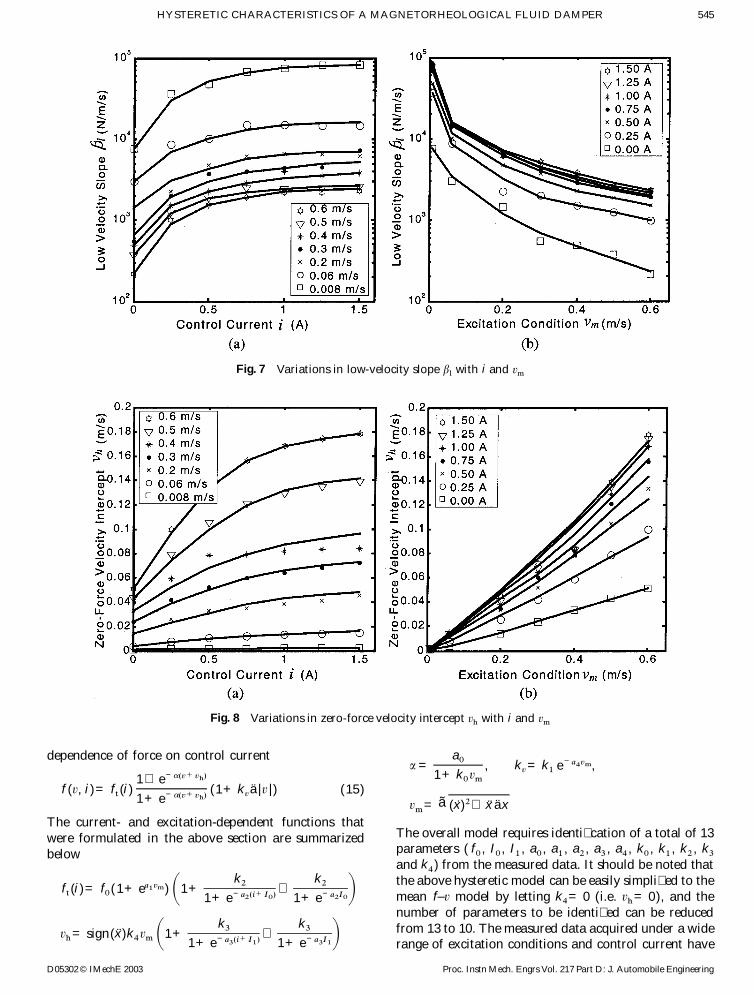
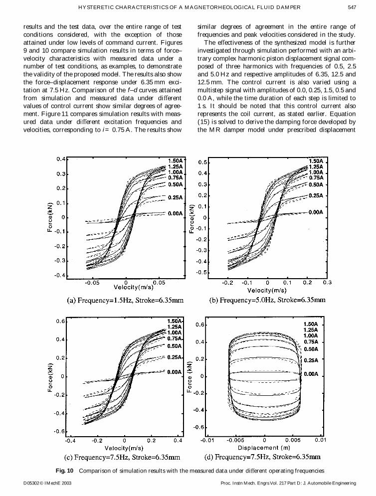