Embed Size (px)
Citation preview

Mechanics and Mechanical EngineeringVol. 15, No. 4 (2011) 115–130c⃝ Technical University of Lodz
Modelling and Investigation of DynamicParameters of Tracked Vehicles
Arkadiusz MezykEugeniusz Switonski
S lawomir KciukWojciech Klein
Silesian University of TechnologyFaculty of Mechanical EngineeringDepartment of Applied Mechanics
Received (13 January 2012)Revised (23 Januaryr 2012)Accepted (27 January 2012)
The paper deals with some results of the research dedicated to mechatronic design andmachinery dynamics of special vehicles conducted in the Department of Applied Mechan-ics. The selected important aspects of the tracked vehicles dynamic modelling processrelated to dynamics of the drive system and the suspension of selected tracked vehiclesare presented.
Keywords: Tracked vehicle, magnetorheological damper, shock absorber
1. Introduction
The research and development process dedicated to new generations of militaryspecial vehicles continuously tends to employ more and more advanced technologies,including methods of modelling and numerical simulations. These methods becomeindispensable for the mechatronic engineering procedures, in particular during earlyphases of the designing practice. The important aspect of the design process in themechatronic engineering is the use of the synergy effect of research methods in orderto achieve the best possible geometrical features and to accomplish the requiredoperational parameters. The example of such an approach is the engineering anddesign process for a military vehicles aided by results of numeric computations withrespect to modelling, analysis of sensitivity and optimization of dynamic propertiesdemonstrated by various systems.
When the initial assumptions for a new design are developed together withthe required engineering documentation for a prototype it is necessary to definethe target structure of the system and its geometrical attributes. It is the basis

116 Mezyk, A., Switonski, E., Kciuk, S. and Klein, W.
that enables to carry out identification of the assumed model and to estimate itsparameters. The further phases of the efforts include also optimization of the designwith the aim to achieve the desired dynamical properties.
For several years the Department of Applied Mechanics of the Silesian Uni-versity of Technology has been dealing with the research programs dedicated tomechatronic design and machinery dynamics to various applications, including alsospecial vehicles. In the paper will be presented only some important aspects of thetracked vehicles dynamic modelling process related to dynamics of the drive systemand the suspension of selected tracked vehicles.
2. Modelling of a hybrid drive for a tracked vehicle
In practice, the issue of the crucial importance are dynamic loads that result frommovements of the vehicle and exert a continuous impact to the vehicle body andmembers of the squad. It is why intense investigations are carried out with the aimto alleviate the adverse impact of such phenomena. However, the optimum selectionof parameters affecting the operation quality of the driveline and suspension needsto develop a dynamic model of a vehicle.
The design of presented tracked platform with a hybrid driving system hasbeen provided by the scientific and industrial consortium that included the SilesianUniversity of Technology, WASKO SA., the AGH University of Technology and theCPW HSW in Stalowa Wola.
Figure 1 The circle of the mechatronic engineering process of the tracked vehicle with a hybriddriving system

Modelling and Investigation of Dynamic ... 117
Model dynamiczny uk³adunapêdowego
Opory skrêtu Opory toczenia
Model dynamiczny silników
elektrycznych
Prêdkoœæ oraz
przyœpieszenie g¹sienicyprawej
Prêdkoœæ oraz
przyœpieszenie g¹sienicylewej
Opory bezw³adnoœci
Model dynamiczny baterii
akumulatorów
Kinematyka pojazdu
Model dynamiczny silnikaspalinowego
Model dynamiczny przek³adnig³ównej
Figure 2 The structure of the dynamic model for the vehicle and the graphic Human–MachineInterface (HMI) with illustration of kinematic parameters for the demonstrative model of thevehicle with a hybrid driving system
The dynamic model of the driving system for the demonstrative model of a trackedvehicle has been developed and implemented with the MATLAB/SIMULINK soft-ware environment. This model comprises some modules, such as the model of aninternal combustion engine, the models of electric motors, rechargeable batteriesand the main transmission gear. The completed simulation experiments enabledto determine traction characteristics of the hybrid driving system and the trackedvehicle as a whole. The graphic interface of the newly developed model that isshown in Fig. 2 enables easy adjustment of dynamic parameters associated withindividual components of the driving system.
0 20 40 60 80 100-150
-100
-50
0
50
100
150
Czas [s]
Mom
ent
siln
ika
lew
ego
[Nm
]
Torq
ue
of
the
left
moto
r[N
m]
Figure 3 Torque of the left motor
118 Mezyk, A., Switonski, E., Kciuk, S. and Klein, W.
0 20 40 60 80 100-150
-100
-50
0
50
100
150
Czas [s]
Mom
ent
siln
ika
pra
weg
o[N
m]
To
rque
of
the
left
rig
ht
[Nm
]
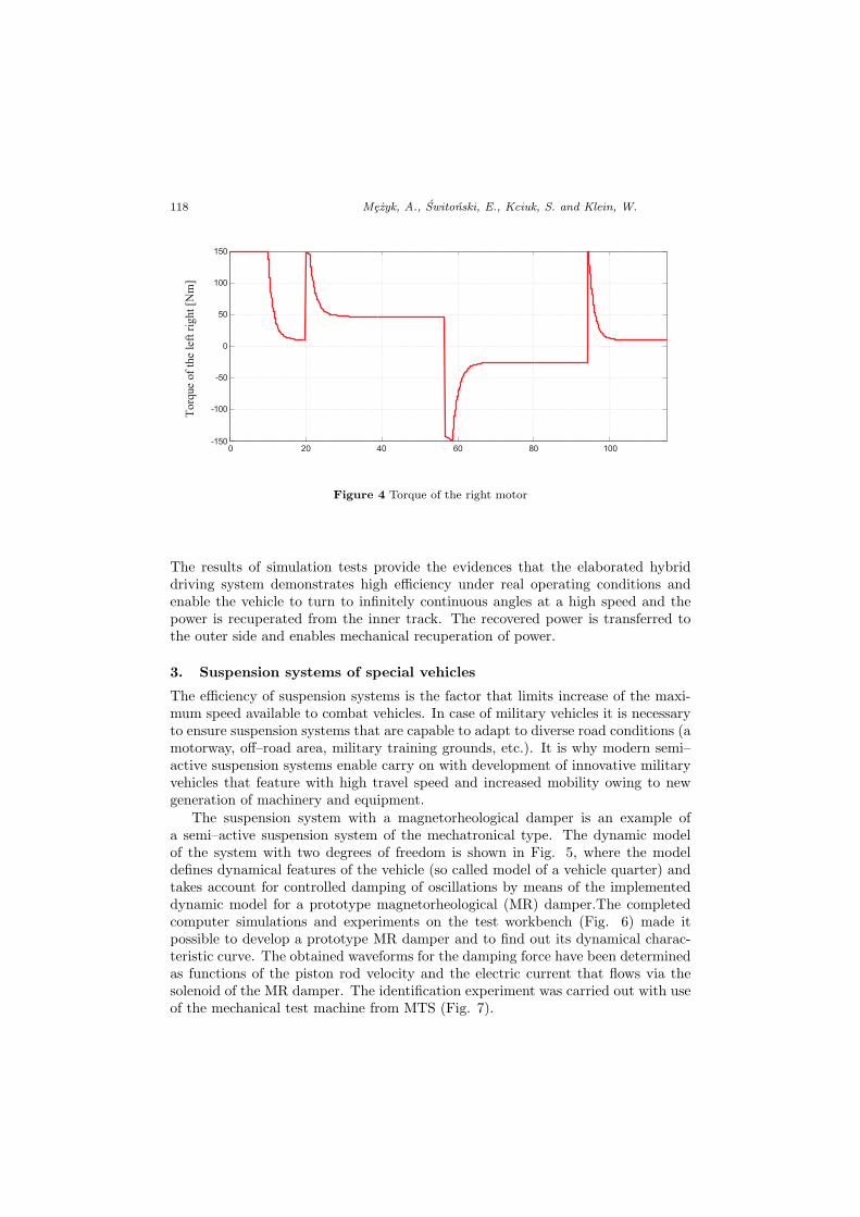
Figure 4 Torque of the right motor
The results of simulation tests provide the evidences that the elaborated hybriddriving system demonstrates high efficiency under real operating conditions andenable the vehicle to turn to infinitely continuous angles at a high speed and thepower is recuperated from the inner track. The recovered power is transferred tothe outer side and enables mechanical recuperation of power.
3. Suspension systems of special vehicles
The efficiency of suspension systems is the factor that limits increase of the maxi-mum speed available to combat vehicles. In case of military vehicles it is necessaryto ensure suspension systems that are capable to adapt to diverse road conditions (amotorway, off–road area, military training grounds, etc.). It is why modern semi–active suspension systems enable carry on with development of innovative militaryvehicles that feature with high travel speed and increased mobility owing to newgeneration of machinery and equipment.
The suspension system with a magnetorheological damper is an example ofa semi–active suspension system of the mechatronical type. The dynamic modelof the system with two degrees of freedom is shown in Fig. 5, where the modeldefines dynamical features of the vehicle (so called model of a vehicle quarter) andtakes account for controlled damping of oscillations by means of the implementeddynamic model for a prototype magnetorheological (MR) damper.The completedcomputer simulations and experiments on the test workbench (Fig. 6) made itpossible to develop a prototype MR damper and to find out its dynamical charac-teristic curve. The obtained waveforms for the damping force have been determinedas functions of the piston rod velocity and the electric current that flows via thesolenoid of the MR damper. The identification experiment was carried out with useof the mechanical test machine from MTS (Fig. 7).

Modelling and Investigation of Dynamic ... 119
Figure 5 The model of a semi–active suspension system with a MR damper and a control system
a) b) c)
Figure 6 Results from numerical computations for the magnetic contour of the MR damper : a)map of magnetic induction, b) distribution of induction vectors, c) magnetic flux as the functionof the gap width (by T. Machoczek)
The program of tests included determination of dynamic characteristic curvesfor various values of the electric current in the solenoid and for various velocities ofthe piston rod. The obtained characteristic curves for selected parameters from theadopted intervals are shown in Fig. 8 and 9.
The recorded experimental characteristic curves that reflect the dynamic prop-erties of the prototype MR damper were used to develop the dynamic model of thedamper with consideration to its geometrical shape (working stroke of the pistonrod), where the Simulink software package was used as the modelling tool. Thecompleted numerical simulations made it possible to draw up waveforms for dis-placements, velocities, absolute and relative acceleration values of both the cush-ioned and non–cushioned weight. The input function was assumed as harmonicoscillations. The selected simulation results are shown in the drawings below.

120 Mezyk, A., Switonski, E., Kciuk, S. and Klein, W.
Figure 7 Test workbench for determination of dynamic characteristics parameters demonstratedby the prototype MR damper
0 0.5 1 1.50
500
1000
1500
2000
2500
3000
Velocity [m/s]
0 A
0.1 A
0.3 A
0.5 A
1 A
2 A
3 A
4 A
5 A
Dampingcoefficient[Ns/m]
Figure 8 The family of characteristic curves for the damping force as the function of the pistonrod velocity and for various values of electric current in the solenoid of the prototype MR damper

Modelling and Investigation of Dynamic ... 121
-1 -0.8 -0.6 -0.4 -0.2 0 0.2 0.4 0.6 0.8 1-1200
-1000
-800
-600
-400
-200
0
200
400
Velocity, [m/s]
Ic=0.00 A
0.26
0.52
1
Force, [N]
Figure 9 The family of characteristic curves for the damping force as the function of threevelocities of the piston rod for the value of electric current in the solenoid equal to 0 A
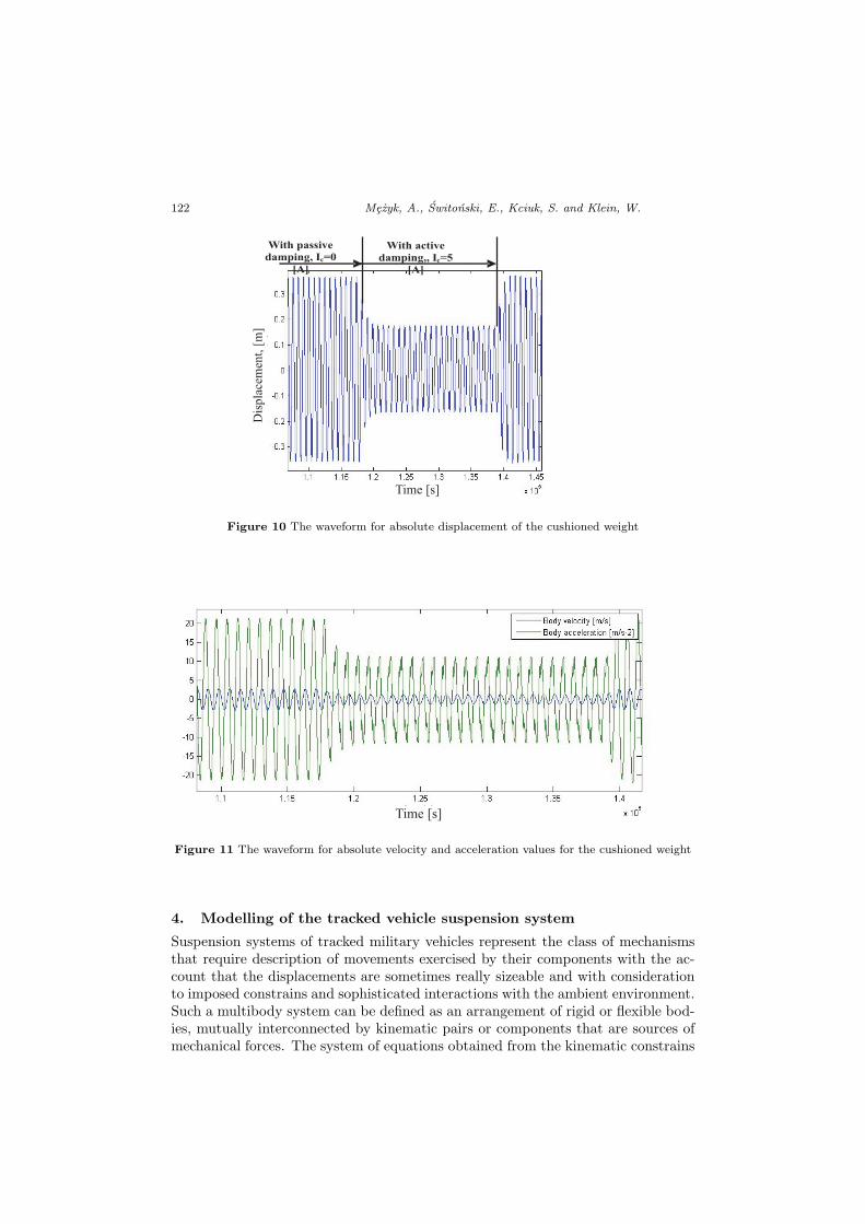
The Fig. 10 and 11 show how displacements, velocity and acceleration of thecushioned weight differ from one another depending on whether the control systemfor the magnetorheological (MR) damper is on or off. The resonance frequency isthe same for the both cases and equals to 1.25 [Hz].
Simulation of movements performed by tracked vehicles need to develop muchmore extensive and sophisticated models that take account for the lack of symmetryagainst the crosswise axis of the vehicle or, under certain conditions, also the lackof symmetry against the longitudinal axis of the vehicle (e.g. rotation of the turret,reconfiguration of the attached equipment, etc.).
122 Mezyk, A., Switonski, E., Kciuk, S. and Klein, W.
Dis
pla
cem
ent,
[m]
Time [s]
With passive
damping, Ic=0
[A]
With active
damping,, Ic=5
[A]
Figure 10 The waveform for absolute displacement of the cushioned weight
Time [s]
Figure 11 The waveform for absolute velocity and acceleration values for the cushioned weight
4. Modelling of the tracked vehicle suspension system
Suspension systems of tracked military vehicles represent the class of mechanismsthat require description of movements exercised by their components with the ac-count that the displacements are sometimes really sizeable and with considerationto imposed constrains and sophisticated interactions with the ambient environment.Such a multibody system can be defined as an arrangement of rigid or flexible bod-ies, mutually interconnected by kinematic pairs or components that are sources ofmechanical forces. The system of equations obtained from the kinematic constrains

Modelling and Investigation of Dynamic ... 123
and driving components can be combined in a consistent manner into a global vectorof constraints denoted as Φ and expressed in the form of the following equation:
Φ (q, t) = 0 (1)
where: q is a vector of generalized coordinates and t stands for time.Within the system of bodies subjected to constrains of movements, the bodies
are interconnected by means of internal kinematic forces. The reaction forces thatact in constraints and are also rated to the forces that constrain movements, aredenoted by the gΦ vector whilst the sum of active and passive forces, denoted as g,describes all forces that act onto the system and its movements is described by theequation:
Mh = g + gΦ (2)
where: M is a global matrix of inertia that comprises masses and mass–relatedmoments of inertia for all the bodies within the system, whilst h stands for thevector of accelerations. The g represents the vector of generalized forces.
For a constrained multimodular system that is made up of n bodies, the equa-tions of motion for a single body can be repeated n times in order to find outequations for the entire system. It leads to equations of motion for a constrainedsystem, where the equations are written in the form:
Mh−BTλ = g (3)
The equation (3) represents a system of n differential equations with n+munknownvariables that correspond to the acceleration vector of h and the Lagrange vectorof multipliers. To resolve the system of these equations it is necessary to formulatem additional equations. Preferably, these additional equations should be obtainedfrom the equations for constraints (1) so that to guarantee that both the equations ofmotion as well as kinematic constraints shall be fulfilled. However, in case of such aprocedure, it is really difficult to find a solution for a system of n+m differential andalgebraic equations. It is why the second derivatives of the equations for constraintsare substitutes with equations for constraints on the level of acceleration:
Φ = 0 ≡ Bh = γ∗ (4)
The equations (4) are appended to the equations of motions, thus the equations forthe constrained system can be written in the matrix form:[
M BT
B 0
] [h−λ
]=
[gγ∗
](5)
where: B is the modified matrix of a Jacobian determinant that is expressed by theequation:
B =[Φr1 ;
12Φp1L
T1 ; · · · ;Φrnb
; 12ΦpnbLTnb
], (6)
whilst γ∗ can be calculated from the equation (6), which is a modified right–handside of the equation of acceleration. Now, the total number of equations is the sameas the total number of unknown variables that correspond to values of accelerationand Lagrange multipliers.

124 Mezyk, A., Switonski, E., Kciuk, S. and Klein, W.
Nowadays, the modelling phase of the design process usually involves moderntools to create virtual prototypes of machines or vehicles. It is possible to developboth 2D models with concentrated parameters or 3D models that can be resolvedwith use of dedicated software tools, such as ADAMS or LMS Virtual Lab Motion.
The entire process of simulation studies and reliability of results obtained fromnumerical computations depend on accurate identification of dynamic models. Thekey issue is estimation of parameters attributable to models, in particular charac-teristics of energy dissipation by shock absorbers (dampers) installed in suspensionsystems. Characteristic parameters of shock absorbers can be acquired by meansof experimental measurements or by numerical simulation of phenomena that takeplace inside the devices. Such simulations are carried out by means of the FiniteElements Method (FEM), where, in case of a hydraulic shock absorber, the liquidchamber is subjected to discretization. The investigations of discrete models providegeneral operational characteristics of shock absorbers, which makes it possible toselect their operational parameters in a best possible way. Fig. 12 shows an exampleof such a numerical simulation for flow of liquid through a valve of a linear damper.Such studies are time–consuming and need application of dedicate software, butthey enable to optimize the design of a shock absorber (damper) and to adapt itscharacteristic parameters to the dynamic behaviour of the vehicle suspension.
Figure 12 The FEM analysis for flow of liquid via a valve of a linear damper (by J. Gni lka)
Modelling and Investigation of Dynamic ... 125
5. Simulation and experimental testing of of the tank suspension system
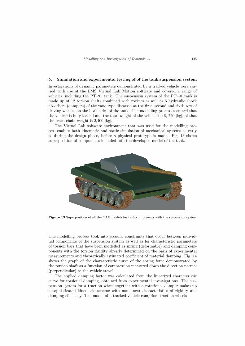
Investigations of dynamic parameters demonstrated by a tracked vehicle were car-ried with use of the LMS Virtual Lab Motion software and covered a range ofvehicles, including the PT–91 tank. The suspension system of the PT–91 tank ismade up of 12 torsion shafts combined with rockers as well as 6 hydraulic shockabsorbers (dampers) of the vane type disposed at the first, second and sixth row ofdriving wheels, on the both sides of the tank. The modelling process assumed thatthe vehicle is fully loaded and the total weight of the vehicle is 46, 220 [kg], of thatthe track chain weight is 2,400 [kg].
The Virtual Lab software environment that was used for the modelling pro-cess enables both kinematic and static simulation of mechanical systems as earlyas during the design phase, before a physical prototype is made. Fig. 13 showssuperposition of components included into the developed model of the tank.
Figure 13 Superposition of all the CAD models for tank components with the suspension system
The modelling process took into account constraints that occur between individ-ual components of the suspension system as well as for characteristic parametersof torsion bars that have been modelled as spring (deformable) and damping com-ponents with the torsion rigidity already determined on the basis of experimentalmeasurements and theoretically estimated coefficient of material damping. Fig. 14shows the graph of the characteristic curve of the spring force demonstrated bythe torsion shaft as a function of compression measured down the direction normal(perpendicular) to the vehicle travel.
The applied damping factor was calculated from the linearized characteristiccurve for torsional damping, obtained from experimental investigations. The sus-pension system for a traction wheel together with a rotational damper makes upa sophisticated kinematic scheme with non–linear characteristics of rigidity anddamping efficiency. The model of a tracked vehicle comprises traction wheels

126 Mezyk, A., Switonski, E., Kciuk, S. and Klein, W.
Figure 14 The characteristic curve for the spring force of torsion shafts, the letters w1 – w6correspond to numbers of torsion shafts
and tracks as well. The scope of experiments assumed that for each wheel the sub-strate profile shall be defined and the wheel shall travel thereon. For the simulationit was adopted that six traction wheels on the left–hand side of the tank travel ona flat plane whilst the right–hand side encounters an obstacle with the height ofabout 30 cm, which corresponds to the circumstances when the right–hand track ofthe tank has to run over an obstacle under field conditions.
The model of the tank that runs over the obstacle is shown in Fig. 15.
Figure 15 Simulation on travelling over an obstacle
One of the simplest techniques that enables to find out kinematic parameters forselected components of the vehicle consists is the photogrametric approach. Themethod assumes that the kinematic variables are measured with use of digitalrecording CCTV cameras, where the motion of the examined facilities is initiallyrecorded and then the images are subjected to the digital frame–by–frame analysis.

Modelling and Investigation of Dynamic ... 127
a)b)
Figure 16 Deployment of CCTV cameras down the path of measurements
Figure 17 Deployment of markers on the tank
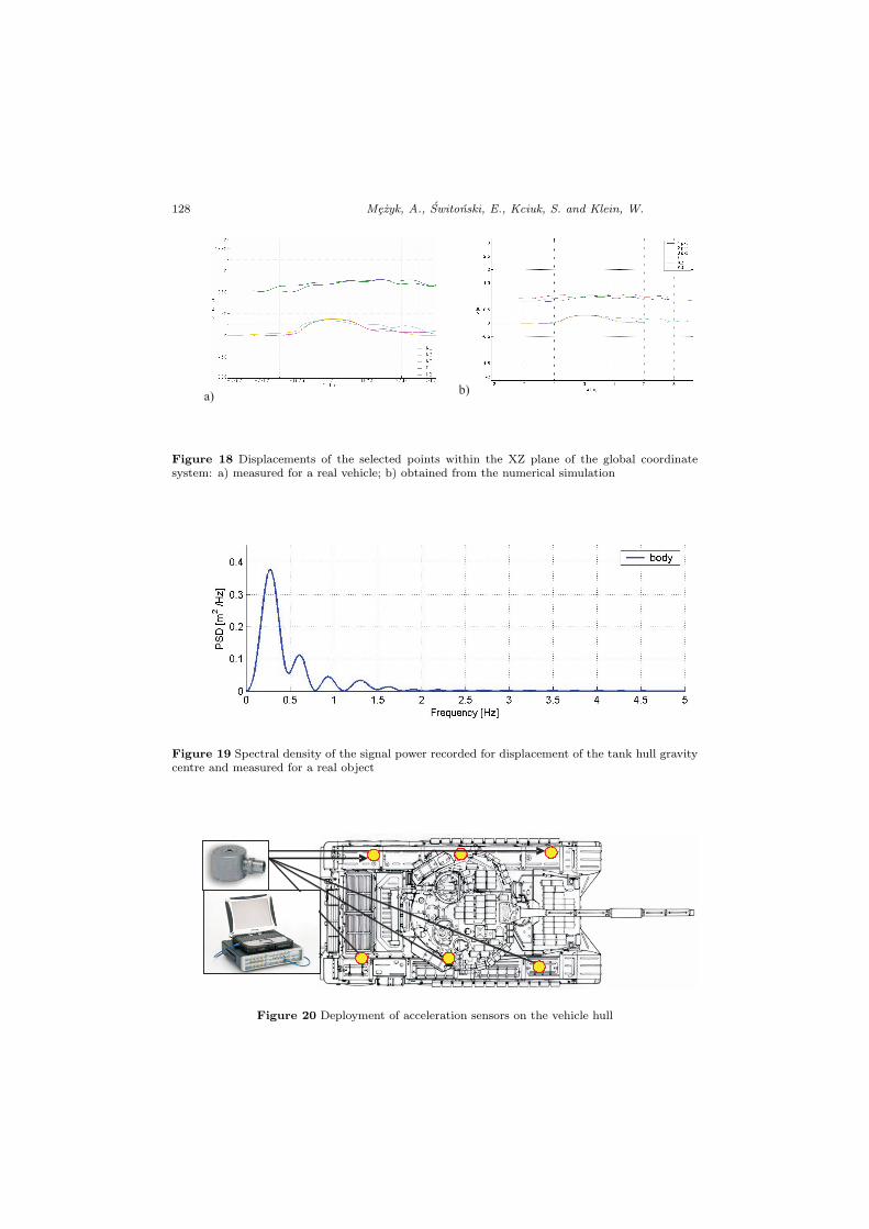
The analysis of recorded images makes it possible to determine coordinates of themarkers already deployed on the tank. The coordinates, in turn, enable calculationof absolute and relative displacements, velocities and accelerations for selected com-ponents of the vehicle. Owing to the MATLAB software environment it is possibleto find out the desired kinematic parameters, to plot graphs and carry on withfurther processing and analysis of the obtained results. The Fig. 18 presents resultsfrom both numerical simulations and field tests.
Another way that allows verifying assumptions adopted for virtual modellingof dynamic behaviour demonstrated by a tracked vehicle consists in measurementof acceleration values for specific points on the tank body. The measurements aretaken with use of a multi–channel recorder, e.g. LMS SCADAS III and an advancedsystem for measurements of vibrations.
128 Mezyk, A., Switonski, E., Kciuk, S. and Klein, W.
a)b)
Figure 18 Displacements of the selected points within the XZ plane of the global coordinatesystem: a) measured for a real vehicle; b) obtained from the numerical simulation
Figure 19 Spectral density of the signal power recorded for displacement of the tank hull gravitycentre and measured for a real object
Figure 20 Deployment of acceleration sensors on the vehicle hull

Modelling and Investigation of Dynamic ... 129
The system enables accurate and repeatable measurements of selected signals whilethe tests are carried out under field conditions (Fig. 21). Another advantage of thesystem is high speed of data acquisition. The method makes it possible to recordacceleration values when the vehicle travels over terrain obstacles, which serves asthe basis for verification whether the results of virtual modeling are correct as thevalues of forces that act onto the tank hull can be measured and compared.
Figure 21 Examples of results for the values of displacement, longitudinal and vertical velocitiesand acceleration for the investigated model of the tank hull
6. Conclusions
Creation of numerical models, designing and optimization of subassemblies andindividual units proved possible owing to modern methods of computer engineeringand sophisticated software. However, the complexity degree of the problem thatthe engineering practice has to deal with as well as the need to apply advancescomputation techniques imposes the necessity of very close collaboration betweenthe scientific centres and industrial companies, both in the area of fundamentalresearch studies and in implementation of new technologies to the manufacturingpractice. The presented paper is just a result of such close collaboration betweenthe Department of Applied Mechanics and companies of the military industry aswell as civil and military universities.
References
[1] Honlinger, M., Glauch, U. and Steger G.: Modelling and simulation in the designprocess of armored vehicles, Paper at the RTO AVT Symposium on ”Reduction ofMilitary Vehicle Acquisition Time and Cost through Advanced Modelling and VirtualSimulation”, Paris, France, published in RTO – MP – 089, 2002.
[2] Kania, E.: Development tendency of landmine protection devices, Modelling andOptimization of Physical Systems, 8, pp. 67–72, Gliwice, 2009.

130 Mezyk, A., Switonski, E., Kciuk, S. and Klein, W.
[3] Kciuk, S., Mezyk, A. and Mura, G.: Modelling of tracked vehicle dynamics,Journal of KONES, vol. 17, no. 1, p. 223–232, 2010.
[4] Kciuk, S., Turczyn, R. and Kciuk, M.: Experimental and numerical studies ofMR damper with prototype magnetorheological fluid, Journal of Achievements inMaterials and Manufacturing Engineering, Vol. 39, Issue 1, ISSN 1734–8412, 2010.
[5] Mezyk, A., Kciuk, S. and Klein, W.: Modelling of mechatronic vibroisolationsystem, Transfer of innovation to the interdisciplinary teaching of mechatronics forthe advanced technology needs, ISBN 978–83–60691–56–4, OW, Opole, 2009.
[6] Report of the research project No. R00004805 – ”Autonomous and Universal trackedplatform for logistic and combat tasks according to standards of modern battlefields”,in polish, 2008 – 2010.
[7] Switonski, E., Mezyk, A., Duda, S. and Kciuk, S.: Prototype magnetorheo-logical fluid damper for active vibration control system, Journal of Achievements inMaterials and Manufacturing Engineering, vol. 21–1, Gliwice, 2006.