Embed Size (px)
Citation preview
International Research Journal of Engineering and Technology (IRJET) e-ISSN: 2395 -0056
Volume: 02 Issue: 06 | Sep-2015 www.irjet.net p-ISSN: 2395-0072
© 2015, IRJET ISO 9001:2008 Certified Journal Page 619
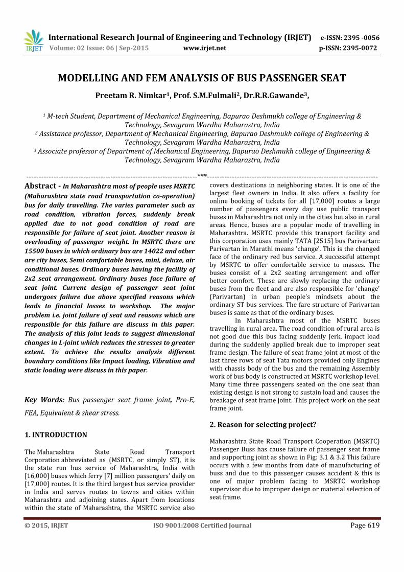
MODELLING AND FEM ANALYSIS OF BUS PASSENGER SEAT
Preetam R. Nimkar1, Prof. S.M.Fulmali2, Dr.R.R.Gawande3,
1 M-tech Student, Department of Mechanical Engineering, Bapurao Deshmukh college of Engineering & Technology, Sevagram Wardha Maharastra, India
2 Assistance professor, Department of Mechanical Engineering, Bapurao Deshmukh college of Engineering & Technology, Sevagram Wardha Maharastra, India
3 Associate professor of Department of Mechanical Engineering, Bapurao Deshmukh college of Engineering & Technology, Sevagram Wardha Maharastra, India
---------------------------------------------------------------------***---------------------------------------------------------------------
Abstract - In Maharashtra most of people uses MSRTC
(Maharashtra state road transportation co-operation)
bus for daily travelling. The varies parameter such as
road condition, vibration forces, suddenly break
applied due to not good condition of road are
responsible for failure of seat joint. Another reason is
overloading of passenger weight. In MSRTC there are
15500 buses in which ordinary bus are 14022 and other
are city buses, Semi comfortable buses, mini, deluxe, air
conditional buses. Ordinary buses having the facility of
2x2 seat arrangement. Ordinary buses face failure of
seat joint. Current design of passenger seat joint
undergoes failure due above specified reasons which
leads to financial losses to workshop. The major
problem i.e. joint failure of seat and reasons which are
responsible for this failure are discuss in this paper.
The analysis of this joint leads to suggest dimensional
changes in L-joint which reduces the stresses to greater
extent. To achieve the results analysis different
boundary conditions like Impact loading, Vibration and
static loading were discuss in this paper.
Key Words: Bus passenger seat frame joint, Pro-E,
FEA, Equivalent & shear stress.
1. INTRODUCTION The Maharashtra State Road Transport Corporation abbreviated as (MSRTC, or simply ST), it is the state run bus service of Maharashtra, India with [16,000] buses which ferry [7] million passengers’ daily on [17,000] routes. It is the third largest bus service provider in India and serves routes to towns and cities within Maharashtra and adjoining states. Apart from locations within the state of Maharashtra, the MSRTC service also
covers destinations in neighboring states. It is one of the largest fleet owners in India. It also offers a facility for online booking of tickets for all [17,000] routes a large number of passengers every day use public transport buses in Maharashtra not only in the cities but also in rural areas. Hence, buses are a popular mode of travelling in Maharashtra. MSRTC provide this transport facility and this corporation uses mainly TATA [2515] bus Parivartan: Parivartan in Marathi means 'change'. This is the changed face of the ordinary red bus service. A successful attempt by MSRTC to offer comfortable service to masses. The buses consist of a 2x2 seating arrangement and offer better comfort. These are slowly replacing the ordinary buses from the fleet and are also responsible for 'change' (Parivartan) in urban people's mindsets about the ordinary ST bus services. The fare structure of Parivartan buses is same as that of the ordinary buses. In Maharashtra most of the MSRTC buses travelling in rural area. The road condition of rural area is not good due this bus facing suddenly Jerk, impact load during the suddenly applied break due to improper seat frame design. The failure of seat frame joint at most of the last three rows of seat Tata motors provided only Engines with chassis body of the bus and the remaining Assembly work of bus body is constructed at MSRTC workshop level. Many time three passengers seated on the one seat than existing design is not strong to sustain load and causes the breakage of seat frame joint. This project work on the seat frame joint.
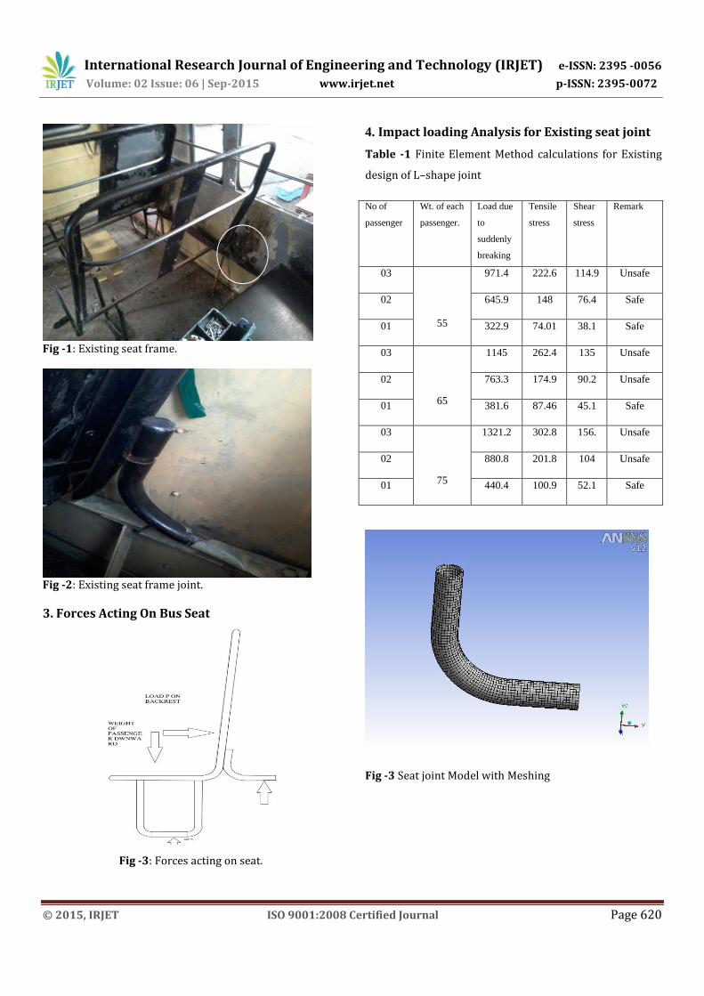
2. Reason for selecting project? Maharashtra State Road Transport Cooperation (MSRTC) Passenger Buss has cause failure of passenger seat frame and supporting joint as shown in Fig: 3.1 & 3.2 This failure occurs with a few months from date of manufacturing of buss and due to this passenger causes accident & this is one of major problem facing to MSRTC workshop supervisor due to improper design or material selection of seat frame.
International Research Journal of Engineering and Technology (IRJET) e-ISSN: 2395 -0056
Volume: 02 Issue: 06 | Sep-2015 www.irjet.net p-ISSN: 2395-0072
© 2015, IRJET ISO 9001:2008 Certified Journal Page 620
Fig -1: Existing seat frame.
Fig -2: Existing seat frame joint.
3. Forces Acting On Bus Seat
Fig -3: Forces acting on seat.
4. Impact loading Analysis for Existing seat joint
Table -1 Finite Element Method calculations for Existing
design of L–shape joint
No of
passenger
Wt. of each
passenger.
Load due
to
suddenly
breaking
Tensile
stress
Shear
stress
Remark
03
55
971.4 222.6 114.9 Unsafe
02 645.9 148 76.4 Safe
01 322.9 74.01 38.1 Safe
03
65
1145 262.4 135 Unsafe
02 763.3 174.9 90.2 Unsafe
01 381.6 87.46 45.1 Safe
03
75
1321.2 302.8 156. Unsafe
02 880.8 201.8 104 Unsafe
01 440.4 100.9 52.1 Safe
Fig -3 Seat joint Model with Meshing

International Research Journal of Engineering and Technology (IRJET) e-ISSN: 2395 -0056
Volume: 02 Issue: 06 | Sep-2015 www.irjet.net p-ISSN: 2395-0072
© 2015, IRJET ISO 9001:2008 Certified Journal Page 621
Fig -4 Equivalent Stress Distribution for existing joint.
Fig -5 Shear Stress Distribution for existing joint
Fig -6 Equivalent Stress Distribution for Modified joint.
Fig -7 Shear Stress Distribution for Modified joint.
Table -2 Finite Element Method calculation of Modified
design
No of
passenger
Wt. of
each
passenger.
Load due
to
suddenly
breaking
Tensile
stress
Shear
stress
Remark
03
55
971.4 141.6 80.9 Safe
02 645.9 94.21 53.8 Safe
01 322.9 47.09 26.9 Safe
03
65
1145 167 95.4 Nearer
to
02 763.3 111.3 63.6 Safe
01 381.6 55.65 31.8 Safe
03
75
1321.2 192.7 110 Unsafe
02 880.8 128.4 73.4 Safe
01 440.4 64.23 34.7 Safe
International Research Journal of Engineering and Technology (IRJET) e-ISSN: 2395 -0056
Volume: 02 Issue: 06 | Sep-2015 www.irjet.net p-ISSN: 2395-0072
© 2015, IRJET ISO 9001:2008 Certified Journal Page 622
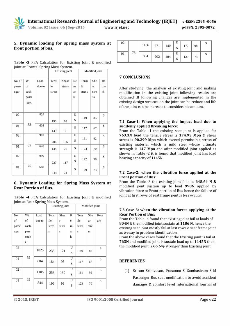
5. Dynamic loading for spring mass system at front portion of bus. Table -3 FEA Calculation for Existing Joint & modified joint at Frontal Spring Mass System. Existing joint Modified joint
No of
passe
nger
Wt.
of
each
passe
nger.
Load
due to
Tensi
le
stress
Shear
stress
Re
m
ar
k
Tensi
le
stress
She
ar
stre
ss
Re
ma
rk
02
55
829
190 98
U
S 149 85
S
01 608
139 7 S 117 67
S
02
65
901
206 106
U
S 161 92
S
01 648 148 76 S 123 70
S
02
75
990
227 117
U
S 172 98
S
01 688
144 74
S 129 73 S
6. Dynamic Loading for Spring Mass System at Rear Portion of Bus.
Table -4 FEA Calculation for Existing Joint & modified joint at Rear Spring Mass System. Existing joint Modified joint
No
of
passe
nger
Wt.
of
each
pass
enge
r.
Load
due to
Tens
ile
stres
s
Shea
r
stres
s
R
e
m
ar
k
Tens
ile
stres
s
She
ar
stre
ss
Rem
ark
02
55
1025 235 121 U
S 149 85
S
01 804 184 95
U
S 117 67
S
02
65
1105 253 130 U
S 161 92
S
01 844 193 99
U
S 123 70
S
02
75
1186 271 140 U
S 172 98
S
01 884 202 104
U
S 129 73
S
7 CONCLUSIONS
After studying the analysis of existing joint and making modification in the existing joint following results are obtained .If following changes are implemented in the existing design stresses on the joint can be reduce and life
of the joint can be increase to considerable amount.
7.1 Case-1: When applying the impact load due to suddenly applied Breaking force: From the Table -1 the existing seat joint is applied for 763.3N load the tensile stress is 174.95 Mpa & shear stress is 90.299 Mpa which exceed permissible stress of existing material which is mild steel whose ultimate strength is 147 Mpa and after modified joint applied as shown in Table -2 it is found that modified joint has load bearing capacity of 1145N.
7.2 Case-2: when the vibration force applied at the Front portion of Bus: From the Table -3 the existing joint fails at 648.64 N & modified joint sustain up to load 990N applied by vibration force at Front portion of Bus hence the failure of joint at first rows of seat frame joint is less occurs.
7.3 Case-3: when the vibration forces applying at the Rear Portion of Bus: From the Table -4 found that existing joint fail at loads of 804N & the modified joint sustain at 1186 N. hence the existing seat joint mostly fail at last rows o seat frame joint as we say in problem identification. From the above cases found that the Existing joint is fail at 763N and modified joint is sustain load up to 1145N then the modified joint is 66.6% stronger than Existing joint.
REFERENCES
[1] Sriram Srinivasan, Prasanna S, Sambasivam S M
Passenger Bus seat modification to avoid accident
damages & comfort level International Journal of

International Research Journal of Engineering and Technology (IRJET) e-ISSN: 2395 -0056
Volume: 02 Issue: 06 | Sep-2015 www.irjet.net p-ISSN: 2395-0072
© 2015, IRJET ISO 9001:2008 Certified Journal Page 623
Scientific & Engineering Research, Volume 5, Issue
1, January-2014
[2] Hiroyuki Mitsuishi, Yoshihiro Sukegawa, Fujio
Matsukawa [2001], Research on Bus Passenger
Safety in Frontal Impacts Japan Automobil
Manufacturers Association Inc.
[3] Yali Yang, Hao Chen, Ruoping Zhang [2014]
vehicle seat structure optimization in front &rear
impact The Open Mechanical Engineering Journal.
[4] Giuseppe Andreonia,b Giorgio C. Santambrogio
Marco Rabuffetti [2002] Method for the analysis
of posture & interfacepressure of car driver
Applied Ergonomics 33.
[5] Mechanical Vibration by V.P.Sigh Dhanpath rai
publication.
[6] Machine design by Krumi gupta
[7] Mr.Jakob Steinwall , Mr.Patrik Viippola [2014]
Concept Development of a Lightweight Driver’s
Seat Structure & Adjustment System Department
Of Product And Production Development
Chalmers University Of Technology Gothenburg,
Sweden.
[8] Chetan N. Benkar , Dr. N. A. Wankhade [2014]
Finite Element Stress Analysis Of Crane Hook With
Different Cross Sections International Journal For
Technological Research In Engineering Volume 1,
Issue 9.
[9] T.C Fai, F. Delbressineand M. Rauterberg [2007]
Vehicle Seat Design: State Of The Art And Recent
Development In: As. Mokhtar, Ej. Abdullah, Nm
Adam, Ar. Abu Talib, Na. Abdul Jalil, R. Zahari,
Wmi. Hassan & Za. Zulkefli (Eds.) Proceedings
World Engineering Congress Penang Malaysia.
[10] Krishnakant, P.V., Evaluation of ride and activity
comfort for the passengers while traveling by rail
vehicles, M.Tech Dissertation, IIT Roorkee,
Roorkee, India, 2007.
[11] Narayanamoorthy, R., Khan, S., Berg, M., Goel, V.K.,
Saran, V.H., and Harsha, S.P., Determination of
activity comfort in Swedish passenger trains, 8th
World Congress on Railway Research, Seoul,
Korea, 2008.
[12] Cho, Y. and Yoon, Y. S. (2001) Biomechanical
model of human on seat with backrest for
evaluating ride quality. International Journal of
Industrial Ergonomics, 27:331-345.
[13] Rakheja, S., Stiharu, I., Zhang, H. and Boileau, P. E.
(2006) Seated occupant interactions with seat
backrest and pan, and biodynamic response under
vertical vibration. Journal of Sound and Vibration,
298:651-671.
[14] Wang, W., Rakheja, S. and Boileau, P. E. (2006) The
role of seat geometry and posture on the
mechanical energy absorption characteristics of
seated occupants under vertical vibration.
International Journal of Industrial Ergonomics,
36:171-184.
[15] M.V.Srinivasan, M. Lava Kumar [2013] Model and
Analysis on Car Seat Mounting Bracket
International Journal of Computer Trends and
Technology (IJCTT) – volume 4 Issue 8.