Embed Size (px)
Citation preview

Modeling Variation Space of Tailored Messages
Kacper Bak and Rafael Lotufo
Generative Software Development Lab, University of Waterloo, Canada,{kbak,rlotufo}@gsd.uwaterloo.ca
1 Introduction
Persuasive technology is a growing field of research that should be able to changeboth the way we interact with computers, mobiles and electronic systems ingeneral, as well as influence changes to our lifestyle. Persuasive technology inhealthcare, for example, is believed to have a great potential to radically changebehavior of patients towards prevention and treatment, as well as access to in-formation.
Systems that are able to interact with users through personalized messagesare very important in this field, as personalization is believed to improve per-suasiveness and effectiveness of rhetoric [17, 15]. Personalization requires themodeling of the user, and of the tailorable message. However, we have not seena formal notation and semantics for these models. Evermore, the generation(instantiation) of personalized messages given the user configuration and themessage model still has to be manually programmed for every new user andmessage model.
The general problem of modeling variability is well known in the field ofautomated software engineering, which tries to automate production and main-tenance of large software systems. In practice, many of the systems providesimilar functionality but can be tailored on demand. So called software prod-uct lines represent families of related, but customizable, software systems builtfrom shared components. Is is easy to see that there is a direct correspondencebetween modeling software variability and tailored messages in persuasion.
Feature modeling is a standard technique used for capturing commonalitiesand variabilities in software product lines. Feature models are usually representedin various visual notations basing on FODA [14]. Typically they are depictedas tree structures with additional constraints specifying relationships betweenparent feature and its subfeatures.
In this work, we present how feature modeling can be used to formalize theuser and message models of tailored messages. Furthermore, we present Clafer,a notation for representing these models, which which can be used to createan interpreter to generate personalized messages given any user and documentmodel. We will also present an instance of the user and document models basedon data that will be provided to us. Finally, we describe how to easily build aproof of concept tool that allows automatic generation of tailored messages givena user and document model, using existing infrastructure.

The paper is organized as follows. We introduce feature modeling and discussits extensions in Sect. 2. We then formalize variation space of tailored messagesin Sect. 3. We present Clafer in Sect. 4. Sample variation spaces are modeledin Clafer in Sect. 5 and Sect. 6. In Sect. 7 we give overview of existing featuremodeling infrastructure. We discuss related work in Sect. 8 and conclude inSect. 9.
2 Feature Models
Feature models were introduced by Kang [14] to represent and model softwareproducts available in a family of software products — a software product line —where products are represented by a set of features. A valid set of features in asoftware product line compose a valid product, also known as a configuration.
Feature is an abstract and overloaded term. For software product lines, wethink the most appropriate definition is “an increment in program functionality”[13]. This definition can easily be used to describe features for other domainsother than software. As an example, lets consider a product line of automo-biles with the following features: manual transmission, automatic transmission,leather seats, heated seats, cd player, tape and radio. Each one of these featuresadd some sort of “functionality” to the automobile product.
Given the above features, we shall now describe the available automobileproducts that a hypothetical manufacturer produces: automobiles may have ei-ther manual transmission or automatic transmission; leather seats and heatedseats are optional; cd player and tape are optional; if cd player or tape is selectedthen the automobile also has a radio; if an automobile has heated seats then thetransmission must be automatic.
The above textual description of the automobile product line is a set ofconstraints on the features, where only valid products — configurations — adhereto the constraints. Feature models are therefore a visual notation for formalizingthese constraints. Figure 1 shows a feature model that represents the automobileproduct line.
Manual Automatic
Transmission
Leather seats Heated seats
Seats
CD Player Tape
Radio
Automobile
Heated seats → Automatic
Fig. 1. Feature model for automobile product line
2

Transmission ↔ Automobile1Seats ↔ Automobile2Radio → Automobile3
(Manual ∨ Automatic) ∧ (Manual → ¬Automatic) ∧ (Automatic → ¬Manual)4Leather seats → Seats5Heated seats → Seats6
CD Player ∨ Tape7CD Player → Radio8
Tape → Radio9Heated seats → Automatic10
Fig. 2. Propositional formulas for the automotive feature model
As can be seen in Fig. 1, feature models are represented by a feature diagram:a hierarchy of features and special links between features with different symbols.Both hierarchy and symbols add constraints to the feature model. Hierarchyspecifies that for every feature that is selected (except the root feature), itsparent must also be selected. For example, it is not possible to have leatherseats without seats.
As for symbols, a white ball specifies that the feature is optional, as areleather seats and heated seats. Black balls specify that the feature is mandatory,i.e., a car must have transmission and seats. Arcs specify constraints on groupsof features: white arcs are exclusive-or constraints, i.e., a transmission must bemanual or automatic; black arcs are or groups, where at least one feature must beselected, i.e., the radio must have at least a cd player or tape, but can have both.Constraints that can not be represented in the feature diagram are specified asextra-constraints, as are given as propositional formulas together with the featurediagram. The constraint on heated seats is given as heated seats → automatic,where the → symbol means implies.
As can be seen in the example, feature models represent constraints on a con-figuration in a simple and intuitive manner, instead of presenting this variabilitypurely as a set of propositional formulas, or by a list of valid configurations. Itis also evident that feature models are a general representation of valid configu-rations, and can be used to solve and model a wide variety of problems.
2.1 Feature Model and Propositional Formulas
As shown in [2] and [18], feature models can be represented as a propositionalformula, where every feature is a variable in the formula such that only validconfigurations will yield ‘true’. Figure 2 shows the list of propositional formulasfor the automotive feature model show in Fig. 1. The propositional formula forthe feature model is the conjunction of all formulas.
Mandatory features are expressed by ↔ between the parent and mandatorychild feature as shown in lines 1 and 2 in Fig. 2. Hierarchy constraints on optionalfeatures are expressed using implication from child to parent, as shown by theformula on lines 3, 5, 6, 8 and 9. Line 4 shows how the propositional formula
3

for mutual exclusion (xor), and can be adapted to groups of any size. Or groupsare formalized as disjunction of each feature in the group, as shown in line 7.Finally, the extra-constraints are appended to the list of formulas, as shown inline 10.
By transforming feature models to propositional formulas, it is possible toautomate reasoning and formalize its semantics. BDDs and SAT solvers havebeen shown to provide good support for reasoning about feature models [18],and both require as input propositional formulas.
This kind of automation is useful both for feature model creation, as wellas for configuration. When creating feature models, we want to make sure thatthere are no dead features (features that can never be selected), and also thatthe feature model allows all desired configurations and no more. This becomesa hard task as soon as feature models grow in size and number of constraints.As for configuration, we need tools that both assist users in configuration, suchas with choice propagation, as well as makes sure constraints are followed.
2.2 Feature Diagrams and Grammars
Feature diagrams can also be represented as grammars [2]. Figure 3 shows aniterative tree grammar for the automotive feature model. In iterative grammars,repetition is expressed by + and *, for one or more, and zero or more constructs,respectively. Optional features are expressed as [Radio], as in line 1 of Fig. 3.Mutual exclusion groups are expressed by using |, as shown in line 2. Or groupsare written as [CD_Player | Tape]+ as shown in line 4.
Automotive: Transmission Seats [Radio];1Transmission: Manual | Automatic;2Seats: [Leather_seats] [Heated_seats];3Radio: [CD_Player | Tape]+;4
Fig. 3. Grammar for automotive feature model
By transforming feature diagrams to grammars it is possible to representfeature diagrams using textual notation. In Sect. 4 we will present Clafer, agrammar for feature models that is concise, expressive and intuitive, a greatadvance over grammars as shown in Fig. 3.
2.3 Extended Feature Models
Several researchers proposed extensions to feature models, so as to add moreexpressiveness to the feature diagrams. The two most prominent extensions arecardinality-based feature models and the addition of attributes to features.
A notation for cardinality-based feature models were proposed by Czarneckiin [9] and allow cardinalities to groups and individual features. Feature models
4

presented by Kang already have some cardinality: optional features have cardi-nality 0..1, whereas mandatory features have 1..1 cardinality. Cardinality-basedfeature models allow any cardinality to be specified for features and groups offeatures. For example, in the automobile product line a cardinality of 4..6 couldbe added to seats, specifying that automobiles should have from 4 to 6 seats.Figure 4 shows the extended version of the feature model for automobiles withcardinality constraint for the seat feature. To represent such constraints in tra-ditional features models it would be necessary to clone the seat feature to 6features, 4 of which would be mandatory and 2 would be optional. If the manu-facturer would not like to impose a constraint on the maximum number of seats,the cardinality constraint can be written as 4..*, allowing 4 to an infinite numberof seats. The semantics of * in cardinality constraints can not be expressed intraditional feature models. Clearly, adding cardinality to feature models addsexpressiveness with a simple notation.
Manual Automatic
Transmission
Leather seats Heated seats
Seats
CD Player
numCd: Int
Tape
Radio
4..6
Automobile
Heated seats → Automatic1 ≤ numCd ≤ 5
Fig. 4. Extended feature model for automobile product line
Attributes were proposed as an addition to feature models in [8, 3], also withthe objective to add simple notation to feature models. Attributes in featuremodels are very similar to attributes in class diagrams in UML: features mayhave a number of attributes and attributes may have types, such as integers,strings, or even references to other features. In our example, we have added anattribute to CD Player that specifies the number of CDs that can be insertedinto the device at the same time. This attribute is of type integer, and has aconstraint specifying that it must be a number from 1 to 5. Figure 4 shows thisextension to the automobile feature model. In a similar fashion to cardinalityconstraints, attributes can be modeled in traditional feature models by regularfeatures. However, the feature model would explode in the number of featuresand would loose its desired visual conciseness.
5

3 Variation Space
Original feature models are unable to convey the full variation space of tailoredmessages. They are appropriate for describing variabilities but cannot expressconcrete data structures, such as text messages. In the context of variation space,there are conceptual differences between abstract variabilities and concrete datastructures. We propose to split the variation space into problem space and solu-
tion space, and establish a mapping between them (see Fig. 5). Such a construc-tion is well known in the SPL community, where separation of specification andimplementation is the first step towards constructing a product line. It helpedus to identify key domains and separate user features from the textual contentof messages.
Problem
space
Solution
space
User Model Master Document
Mapping
Fig. 5. Problem and solution spaces
The problem space contains user model to describe variations among people.We decided to apply feature modeling, as it naturally captures the required typeof variability. Our model is very generic and represents as much user variabilityas is needed. To represent a single person, we configure the model, i.e. addconstraints to either set or unset each feature. For example, Fig. 6a specifiessample user model, where user prefers only one greeting style. After pickinga particular style, the model has no variability (see Fig. 6c) and becomes aninstance of the feature model.
Formal SemiFormal Informal
Greeting
UserModel
Formal
Greeting
UserModel
a) User Model b) Configuration c) Selected User Feature
Fig. 6. Configured user model
6

The solution space contains master document to represent structure of ageneric message. The structure is mostly defined by feature model, but there arealso solution-specific elements, such as the actual message content. For example,Fig. 7 shows a document with three possible greetings. Each greeting is a con-crete text, e.g. “Dear”. In the master document there are no group restrictionsthat make greetings mutually exclusive. These restrictions will be enforced bymapping between spaces.
“Dear” “Hello” “Hi”
Greeting
MasterDocument
Fig. 7. Master document
The two spaces, although separate, cannot stay in complete isolation. Wecouple them by creating a mapping that expresses dependencies between usermodel and master document. It is defined by attaching cross-tree constraints tothe feature model in Fig. 7. Cross-tree constraints are important part of featuremodeling, but there is no standard notation for combining them with diagrams.We simply add a constraint enclosed in square brackets following the featurename/text in the box (see Fig. 8). In our example we refer to features from theuser model, therefore they are preceded by a path (as the feature Formal is pre-ceded in UserModel.Greeting.Formal). The requires constraint in “Dear” [requires
UserModel.Greeting.Formal] says that presence of “Dear” implies presence of theUserModel.Greeting.Formal feature.
“Dear”[requires UserModel.
Greeting.Formal]
“Hello”[requires UserModel.Greeting.SemiFormal]
“Hi”[requires UserModel.Greeting.Informal]
Greeting
MasterDocument
Fig. 8. Master document with mapping constraints
7

To sum up, we described the variation space by decomposing it into smallersubspaces and providing a mapping. Our approach elegantly couples the twospaces by enforcing dependencies among features and the actual texts. The map-ping is precise enough to automatically configure the solution space by config-uring the problem space. For example, if user prefers formal greeting, then thetailored message will start with “Dear”. All these conceptual constructions canbe concisely expressed in Clafer.
4 Clafer
Clafer is a general-purpose modeling language. Initially, we designed it as a con-venient notation for expressing various aspects of software product lines, suchas commonalities, variabilities, constraints and architectural models. Clafer cap-tures abstractions from class and feature modeling, and provides a lot of syntacticsugar for common constructions. The language is not limited to software-relatedproblems; technically, it can express any statement from the first-order predicatelogic.
Generality of the language makes it suitable for modeling variation spaceof tailored messages. The problem we solve is not very different from our workon software product lines. The only difference lies in what we model, but manyabstractions are the same. In this work, we show a subset of Clafer that ispowerful enough to automatically tailor messages to specific users.
Clafer is a textual language with formal semantics defined by translation toAlloy [12]. It allows us to use Alloy infrastructure, such as the Alloy Analyzerand SAT-solvers, to generate instances of Clafer models. Moreover, the textualrepresentation of feature models, in contrast with graphical notations, requiresonly a text editor to create models.
4.1 Feature Modeling
Feature models in Clafer are very similar to cardinality-based feature modelsaugmented with cross-tree constraints. We present the language by showing shortcode snippets and explaining their meaning.
Clafer’s representation of the feature model from Fig. 6a is visible in Fig. 9a;it consists of hierarchically nested features. The top-most feature is named User-
Model and has one child (Greeting). The language uses code indentation to in-dicate a block of subfeatures. Figure 9b contains the same model, but with ex-panded group and feature cardinalities, and hierarchy indicated by curly braces.
FODA or cardinality-based feature models traditionally distinguished group-ing features from other features. That is, a feature has either a group cardinalityor a feature cardinality attached to it. The two concepts are orthogonal in Clafer,thus each feature has both types of cardinalities.
Feature cardinalities restrict the number of instances of a feature. The car-dinality is specified by an interval m..n, where m ∈ N, n ∈ N ∪ {∗},m ≤ n.Feature cardinality specification is optional and if present, follows the feature
8

name. Clafer provides syntactic sugar similar to syntax of regular expressions: ?denotes 0..1; * denotes 0..∗; and + denotes 1..∗. No explicit feature cardinalitydenotes 1..1 (mandatory) by default, modulo four exceptions explained shortly.For example, Greeting (line 2) in Fig. 9a is mandatory.
UserModel1xor Greeting2
Formal3SemiFormal4Informal5
<0-*> UserModel 1..1 {1<1-1> Greeting 1..1 {2<0-*> Formal 0..1 {}3<0-*> SemiFormal 0..1 {}4<0-*> Informal 0..1 {}5
}6}7
a) Concise notation b) Desugared feature model
Fig. 9. Feature model in Clafer
Group cardinalities constrain the number of child instances i.e., the instancescontained by subfeatures. Group cardinality is specified by an interval 〈m–n〉,with the same restrictions on m and n as for feature cardinalities, or by a key-word: xor denotes 〈1– 1〉; or denotes 〈1– ∗〉; mux denotes 〈0– 1〉; and opt denotes〈0– ∗〉; further, each of the keywords makes subfeatures optional by default. Ifany, a group cardinality specification precedes a feature name. For example, xoron Greeting (line 2) in Fig. 9a states that only one child instance of either Formal
or SemiFormal or Informal is allowed. Because the three subfeatures have no ex-plicit cardinality attached to them, they are all optional (cf. Fig. 9b). No explicitgroup cardinality stands for 〈0– ∗〉, except when it is inherited as illustrated next.
4.2 Feature Reuse
Code reuse is one of the key concepts in software engineering as it improvesprogrammer’s productivity, code quality and flexibility. There are several waysin which the language can support code reuse, i.e. modularization, inheritance,conditional file inclusion, and code clones. Inheritance is at the heart of classmodeling, and therefore is available in Clafer.
There is no notion of feature reuse in the original feature models. The onlymethod was to copy a tree structure and paste into another model. Clafer over-comes this limitation by distinguishing abstract and concrete features. All thefeatures presented so far were concrete features, because they contained theactual feature instances. Abstract features, on the other hand, define abstracttypes that can be reused (extended) by other features. Abstract features arenever instantiated unless extended by a concrete feature. Furthermore, only ab-stract features can be extended by concrete features. Abstract features are alwaystop-level definitions, thus it is impossible to nest them.
9

The syntax of abstract features is very similar to the example in Fig. 9, butsuch a feature is preceded by the abstract keyword, and has no feature cardinal-ity. Figure 10a shows an abstract exclusive-or group of three subfeatures. Thetype definition is extended and instantiated in Fig. 10b. The ProgressDay featureinherits Goal’s group cardinality and subfeatures. It also adds a new feature Strat-
egyDays, which becomes the fourth alternative. Figure 10c depicts the structureof ProgressDay.
abstract xor Goal1Exceeded2Met3Failed4
ProgressDay extends Goal1xor StrategyDays2
IncreaseDays3KeepDays4DecreaseDays5
xor ProgressDay1Exceeded2Met3Failed4xor StrategyDays5
IncreaseDays6KeepDays7DecreaseDays8
a) Abstract feature b) Feature inheritance c) All subfeatures
Fig. 10. Inheritance in Clafer
Clafer offers syntactic sugar for inheritance if the extending feature has thesame name as its superfeature. It is known as quotation, because syntacticallyit is a name of abstract feature preceded by the left quote symbol (‘). Theextending feature inherits all assets of an abstract feature. In this way, we createnew features that, in fact, instantiate abstract features. The mechanism is usefulto define a feature once and reuse it later. Figure 11a shows an example. Thereis an abstract feature color that is either green or blue or brown. The modelcontains two unrelated features: car and eye, and each of them has some color.The meaning of quotation is shown in Fig. 11b, where ‘color is expanded as color
extends color. Although, it might seem confusing, the construction has a well-defined meaning: the left color is name of the new feature, the right color refersto the abstract feature.
4.3 Textual Content
Textual strings go beyond the original feature modeling notation. Combinationof feature models with specific values is known as feature models with attributes.While feature models represent general concepts, strings store specific texts. Herewe present two ways of including strings in Clafer models: 1) inline definition,2) by quotation.
The inline definition is a string placed within double quotes (e.g. line 2 inFig. 12a). In the example, the text is nested under parent feature Greeting andacts as a subfeature. Inline definition creates an implicit feature that stores thecontent. Lack of explicit name prohibits the programmer from referring to the
10

abstract xor color1green2blue3brown4
5car6
‘color78
eye9‘color10
abstract xor color1green2blue3brown4
5car6
color extends color78
eyes9color extends color10
a) Quotation b) Desugared quotation
Fig. 11. Feature model in Clafer
Greeting1‘‘Dear’’2
abstract dear = "Dear"12
Greeting3‘dear4
a) Inline definition b) Quotation
Fig. 12. Textual content in Clafer
feature in constraints. The inline method is preferable if the text is short and isnot meant to be reused or constrained.
The second method, quotation, makes textual content more explicit, allowsfor more expressiveness and is better suited for long texts. As with inheritance,first we need to define the abstract feature, and then instantiate it. In the examplefrom Fig. 12b, line 1 names the textual string by creating an abstract feature.Then the feature is instantiated in line 4 by referring to the quoted dear name.The requirement that abstract features have to be defined at top-level makes thecode more readable and better structured.
4.4 Mapping
Mappings between solution and problem spaces are given by constraints. Techni-cally, cross-tree constraints can be placed in either of the spaces or in a separatefile. Clafer’s constraints are based on Alloy’s relational logic. They concisely ex-press statements from the first-order predicate logic. In this project, however,we used only implications, due to simplicity of the constraints. Constraints arespecified in square brackets, e.g. line 3 in Fig. 13. The statement enforces thatpresence of exceedStepsText implies presence of ProgressSteps.Exceeded. The con-straint is evaluated only if exceedStepsText exists in the model.
Real-world feature models [16] usually contain fairly simple implication con-straints, such as one presented in Fig. 13 . To make our notation more informa-tive, we included the requires keyword to specify implied feature inline, e.g. line
11

ReviewProgressMade1‘exceedStepsText ?2[ProgressSteps.Exceeded]3
Fig. 13. Expanded constraint
2 in Fig. 14. The keyword goes after cardinality constraint and is followed by theimplied feature.
ReviewProgressMade1‘exceedStepsText ? requires ProgressSteps.Exceeded2
Fig. 14. Concise notation
Meaning of the two models in Fig. 13 and Fig. 14 is exactly the same. Fig-ure 15 shows the underlying semantics, by expanding quotation and inserting thesome keyword in the constraint. Mathematically, everything in Clafer is a rela-tion; features are binary relations. Therefore, we require one of the quantifiers:no (zero), one, lone (zero or one), some (at least one) to precede each relation andspecify the number of its elements. In this way, we can treat relational formulasas valid Boolean formulas.
ReviewProgressMade1exceedStepsText extends exceedStepsText ?2[some ProgressSteps.Exceeded]3
Fig. 15. Desugared notation
5 Personal Health Coach
The objective of Personal Health Coach project [10] is to assist physicians in pro-viding personalized information to patients about their health and treatments. Itis believed that automatically tailored messages improve patient’s satisfaction,use of physician time, and hospital resources. In contrast with generic messages,the project takes into account patient’s context to deliver customized content.
Initially, the project used Open Document Text Format (OpenOffice.org) torepresent variation space split into user model and master document. AlthoughODT is an open format, there are disadvantages of using it as underlying datastructure:
12

1. No logical structure. The user model was represented as a table where eachrow corresponded to a feature with subfeatures. Unfortunately, it was unableto clearly express feature hierarchies and other than xor feature groups.Master document contained mappings to the user model, but all of themwere written as textual comments.
2. Complex to analyze. ODT is an open format, but was not created for mod-eling variability. Analysis of a file requires familiarity with the internal fileformat. After parsing the file, the syntax tree must be filtered to removeirrelevant information.
3. Lack of tool support. There are no external tools for checking consistencyof mappings between user model and master document. Furthermore, codegeneration for the user interface and backend was hard to automate andrequired help of a programmer.
4. No formal semantics. It is related to the points mentioned earlier, as lack offormal semantics leads to ambiguous documents, that are hard to analyze.
5. Project specific solution. The approach is not reusable, since there are nogeneric and well-defined structures.
6. Not scalable. The ODT documents were not partitioned into smaller pieces,therefore users could not work concurrently on the project.
We argue that our solution addresses most of the above issues, since Claferhas formally defined syntax and semantics, is very generic and scales by mod-ularization and inheritance. Clafer is still a very young language, so the toolsupport is limited; there is a translator from Clafer to Alloy, but analysis of cer-tain models in the Alloy Analyzer takes some time. On the other hand, thanksto uniform semantics many of the existing class and feature modeling tools couldbe used with Clafer, and we expect to provide this kind of support in the nearestfuture.
5.1 User Model
The structure of user model is presented in Fig. 16. It begins with two abstractexclusive-or groups that indicate whether a particular goal was exceeded, met orfailed. We made the PositiveGoal group abstract since there are several goals in thefeature model that have similar structure (e.g. UserModel.ReviewProgressOverall).They inherit the Exceeded and Met features, and add Failed with additional sub-features. The meaning of Failed is that in case of a failure, some action (modeledas subfeatures) should be taken.
Next is the feature model of user profile. It is composed of six direct sub-features, where user specifies his favorite type of greeting, type of relationship(friendly, encouraging, etc.), and other characteristics. Most of them are ag-gregated either under exclusive-or or mutually-exclusive groups. Feature modelmakes variability explicit by placing group cardinalities before each feature.This variability information was not available in the ODT representation of usermodel. Some variability knowledge existed only in people’s minds.
13

abstract xor PositiveGoal1Exceeded2Met3
4abstract Goal extends PositiveGoal5
Failed67
UserModel8xor Greeting9
Formal10SemiFormal11Informal12
13xor Relationship14--content15
16xor ReviewProgressOverall extends PositivetGoal17
Failed18ProgressWeightLoss extends Goal19xor ProgressIntakeGoal extends PositivetGoal20--content21
22ProgressSteps extends PositiveGoal23
Failed24--content25
MeetGymExceed2627
ProgressDay extends PositiveGoal28--content29
30mux CurrentBarriers31--content32
33xor StrategicStepsOverall34--content35
36xor AppraiseBehaviour37--content38
39xor ReinforceResults40--content41
42mux RestageGoal43--content44
Fig. 16. User model
14

5.2 Master Document
Master document represents generic structure of tailored messages. Figure 17shows excerpt of the code. The document starts with a list of abstract featuresthat define textual strings. Message content is represented either as abstractfeatures (line 1) or inline strings (line 9). As suggested earlier, we placed shortmessages inline, and long messages as abstract features.
There are no group cardinalities attached to features. Although texts aremutually exclusive, the constraint is not expressed explicitly in the master doc-ument. Instead, it is inferred from the user model by attaching constraints tofeatures in the master document. The model contains only requires constraints,thus they express how the final output depends on user’s characteristics.
5.3 Summary
In our opinion, Clafer concisely and naturally expressed variation space of thePersonalized Health Coach project. In contrast with the ODT representation,models are complete and have well-defined semantics. We modeled all the vari-ability either as group cardinalities or requires constraints. Thus, the variationspace is not complex by itself, but the complexity comes from potentially largefeature models with hundreds or thousands possible textual messages. Testing allthe configurations is practically infeasible, but there exist tools that can greatlysupport programmer.
6 Breast Reconstruction
This section briefly shows how we have modeled the user variation space inClafer, for the Breast Reconstruction project, from a flowchart used by doctorsto classify and determine the best response for patients. This flowchart is shownin Fig. 18.
Figure 19 shows the feature model representation for the breast reconstruc-tion user model interpreted from the flowchart shown in Fig. 18. Decisions, suchas ‘Timing’ or ‘Lack of skin’ are modeled with xor. Input and output, such as‘Lymph node dissection?’ and ‘Prophilactic mastectomy?’ questions, are mod-eled as optional features. As for flow reuse, such as ‘Implant variables’ that isa target of ‘Expander exchange timing’ and ‘Implant alone’, we model usinginheritance and abstract features.
The flow chart just shown is very similar to a sequence of questions thatcan be asked to a patient, in order to gather information about his situationand classify his current condition. Several projects using tailored messages haveused questionnaires to model the user variability space. From this example, it iseasy to see that feature models can easily be created from such questionnaires,essentially formalizing the variability of possible answers that make sense for thedomain.
15

abstract activeAmbText = "Since you are already very active, I1know you are very ambitious about your exercise goals"2
3--content4
5MasterDocument6
Introduction7Greeting8"Dear" ? requires Formal9"Hello" ? requires SemiFormal10"Hi" ? requires Informal11
12Connection13--content14
15InterventionCoaching16
Monitoring17--content18
19Reinforcement20
AppraiseBehaviour21‘activeAmbText ? requires Ambitious22‘backOnTractText ? requires MostlyOnTrack23
24ReinforceResultsCongratulate25--content26
27DiscourageNegativeThinking28
29Action30--content31
32GoalSetting33--content34
35ConclusionFrame36--content37
Fig. 17. Master document
7 Feature Model Infrastructure
Feature models are a standard solution for variability modeling in softwareproduct-lines and feature-driven development. There exists a large variety ofpublications on the topic, and also ready available infrastructure for featuremodel editing and configuration.
16
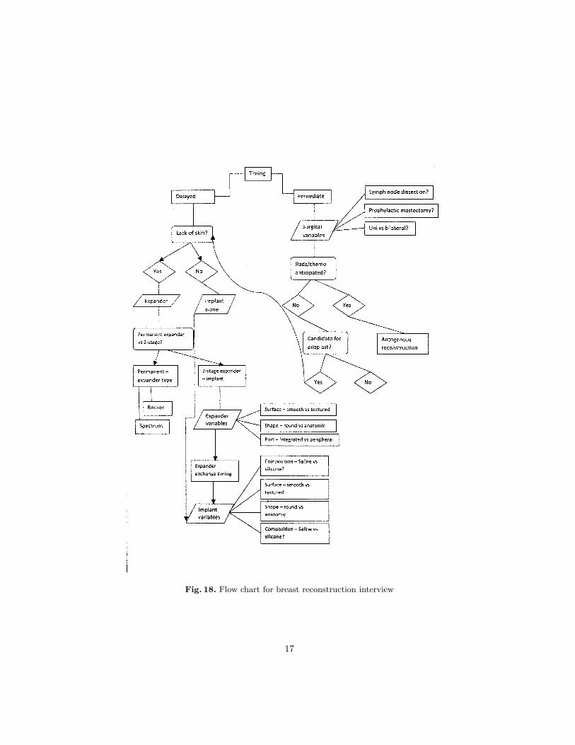
Fig. 18. Flow chart for breast reconstruction interview
17

Figure 20 shows features of possible tools for feature model manipulation.These tools can provide editing capabilities, such as a visual feature model ed-itor, similar to UML model CASE tools, or simple textual editing with syntaxhighlighting and auto-completion. Feature model editors can also have modelchecking capabilities, using SAT solvers and BDDs to reason upon the proposi-tional formula, as explained in Sect. 2.1. Model checking can assist the user in as-suring that the feature model is sound (there are no dead features and that thereexist at least one non-empty configuration that satisfies the model constraints),or even that the model adheres to tests specified by the user. Further editingassistance can be provided by automatically changing explicit constraints, oreven providing support for batch editing, such as moving a group of features aschildren of a common feature.
Feature model tools can also provide simple viewing support, such as render-ing feature models in text files in traditional feature diagram notation, such asused in this document. If a feature model is large, with hundreds or thousandsof features [16], displaying projections or slices of the feature model might bevery useful.
Feature model viewers may also provide features to assist users in configura-tion. Configuring large feature models with complex constraints is not an easytask without appropriate tool support. Choice propagation can help the userin resolving constraints so that a particular feature can be selected. Withoutchoice propagation, users has to manually resolve all transitive constraints ofthe features they wish to select. Another valuable feature for configuration is tobe able to backtrack to previous decisions when the user has changed his mind.This can often be the case in highly constrained feature models, where selectinga feature might restrict selection of other features, and users only become awareof such restrictions when they have already made the first selection.
Tools with product generation are capable of automatically generating com-plete products given a configuration. In the software product line perspective,this is equivalent to generating the resulting software products packaged andready for deployment. For example, the Linux kernel has over 6000 features, anduses meta-programming via pre-compiler directives to direct code generationgiven a configuration of features. Product generation in tailored message per-spective would be the automatic message generation given a user-configuration.
7.1 Proof of Concept Using Existing Infrastructure
In fact, the infrastructure used by the Linux kernel to model, configure and au-tomatically generate products can easily be leveraged for message tailoring. Herewe describe a proof of concept that can be built with existing tools, specifically,the Linux kernel Kconfig infrastructure.
The Linux kernel provides qconf, a configuration tool with simple modelchecking features. The input to qconf are Kconfig scripts, the variability mod-eling language created by the Linux kernel community [4]. When saving config-urations using qconf, it exports the configuration as a special header C file. By
18

creating master documents using pre-compiler directives such as #ifdef, a Cpre-compiler such as CPP can be used to generate tailored messages.
Figure 21 shows a slice of the Health Coach feature model in the qconf config-uration tool. It presents features as choices, and only allows choices that satisfythe model’s constraints. The Kconfig script that represents this model is shownin Fig. 22. We will not cover in details the syntax of Kconfig, as this informationis described in the Linux kernel source tree1.
The master document for Health Coach representing using pre-compiler di-rectives is shown in Fig. 23. By executing qconf and saving a configuration forthe user model, this should generate a conf.h header file defining the user fea-tures present in the configuration. Running master document file through cppwill produce the the tailored document.
Although this approach creates a functional configurator and product gen-erator, Kconfig is not a feature model modeling language, but a script to createthe qconf interface. Evermore, the master document using pre-compiler directiveis not a model either, and is hard to reason upon.
Therefore, we recommend modeling both the user model and master docu-ment using Clafer, as previously explained, and using Kconfig and ifdefs as anintermediate representation, by transforming Clafer models to Kconfig and to amaster document with ifdefs. This transformation is not hard to implement, andthe result produces an executable configurator and product generator.
8 Related Work
Piglit (Patient Information Generated by Loosely Intelligent Techniques) [5] isa text-generation system that provides personalized hypertext explanations ofpatients’ records. The project enabled diabetes patients to learn more about theirconditions and topics mentioned in the records. Focus of our project is different,we presented a generic method for modeling variability that is not related tospecific disease. Furthermore, we did not have access to patient’s record. Instead,we assumed that there is a formal user model with all the relevant information.
The Migraine project [6] generates interactive materials for migraine patientswho can ask follow-up questions via a mixture of hypertext and menu selection.Similarly to out project, Migraine has no access to patent’s record. User’s profileis built from a computer-based interview. In our project, we did not describe anymethod of building user’s profile, but it can be done manually (by the doctor), orinteractively (computer interview), or automatically (mining patient’s record).
OPADE [7] generates personalized leaflets about drugs from existing sourcesof information. These independent sources included a drug database and theprescription. OPADE also tries to resolve potential conflicts between what thedoctor wants to communicate and what the patient wants to know. The purposeof OPADE and our project is very similar. We believe that our formalism couldbe applied as underlying structure in OPADE.
1 The documentation can be found in Documentation/kbuild/kconfig-language.txt
19

HealthDoc [11] is another patient information generation system that usesa master text document to create personalized information material. Text gen-eration first selects the relevant fragments of text from the master documentand then repairs the text to be made grammatically correct and coherent. Ourmethod is based on the idea of tailoring the master document, but we only se-lect parts of the document to create a message. The message is not repairedafterwards.
9 Conclusion
We have shown how feature modeling can be used to model variation spaceof tailored messages. We presented basics of feature modeling and summarizedstate-of-the art knowledge about feature models. Compared to previous textgeneration methods, our approach is formal and based on well-established ideasfrom Software Product Lines. These ideas were captured in Clafer, i.e. generalpurpose modeling language. The notation offers concise syntax for feature andclass models augmented with cross-tree constraints.
Furthermore, the work gave a brief overview of existing feature model infras-tructure. We used the Linux kernel tools to represent and automatically config-ure the master document by selecting features from the user model. It showedthat feature modeling approach is not only formal, but can be easily applied toautomatically tailor messages.
References
1. Antkiewicz, M., Czarnecki, K., Stephan, M.: Engineering of framework-specificmodeling languages. IEEE TSE 35(6), 795–824 (2009)
2. Batory, D.: Feature models, grammars, and propositional formulas. In: SPLC’05.pp. 7–20 (2005)
3. Benavides, D., Trinidad, P., Ruiz-Cortés, A.: Automated reasoning on feature mod-els. In: CAISE 2005. pp. 491–503 (2005)
4. Berger, T., She, S., Lotufo, R., Wąsowski, A., Czarnecki, K.: Variability modellingin the real: A perspective from the operating systems domain. In: FSE’10 (2010),under review
5. Binsted K, Cawsey A, J.R.: Generating personalised information using the medicalrecord. In: AIME’95. pp. 29–41 (1995)
6. Carenini G, Mittal VO, M.J.: Generating patient-specific interactive natural lan-guage explanations. In: The Annual Symposium on Computer Applications in Med-ical Care’94 (1994)
7. de Carolis B, de Rosis F, G.F.: Generating recipient-centered explanations aboutdrug prescription. In: AIM’96. pp. 123–145 (1996)
8. Czarnecki, K., Bednasch, T., Unger, P., Eisenecker, U.: Generative programmingfor embedded software: An industrial experience report. In: GPCE’02. pp. 156–172(2002)
9. Czarnecki, K., Helsen, S., Eisenecker, U.: Staged configuration through specializa-tion and multi-level configuration of feature models. Software Process Improvementand Practice 10(2), 143–169 (2005)
20
10. Dimarco, C., Hirst, G., Wanner, L., Wilkinson, J.: Healthdoc: Customizing patientinformation and health education by medical condition and personal characteris-tics. In: 1st International Workshop on Artificial Intelligence in Patient Education(1995)
11. Hirst G, DiMarco C, H.E.: Authoring and generating health-education documentsthat are tailored to the needs of the individual patient. In: International Conferenceon User Modeling’97 (1997)
12. Jackson, D.: Software Abstractions: Logic, Language, and Analysis. The MIT Press(2006)
13. Jackson, M., Zave, P.: Distributed feature composition: A virtual architecture fortelecommunications services. IEEE TSE 24(10), 831–847 (1998)
14. Kang, K., Cohen, S., Hess, J., Nowak, W., Peterson, S.: Feature-oriented domainanalysis (FODA) feasibility study. Tech. Rep. CMU/SEI-90-TR-21, Carnegie Mel-lon University (1990)
15. Kramish Campbell M, DeVellis B, e.a.: Improving dietary behaviour: the efficacytailored messages in primary care settings. AJPH 84(5), 783–787 (1994)
16. She, S., Lotufo, R., Berger, T., Wasowski, A., Czarnecki, K.: Variability model ofthe linux kernel. In: VaMoS’10. pp. 45–51 (2010)
17. Strecher V, Kreuter M, e.a.: The effects of computer-tailored smoking cessationletters in family practice settings. JFP 39(3), 262–270 (1994)
18. Thüm, T., Batory, D., Kästner, C.: Reasoning about edits to feature models. In:ICSE’09. pp. 254–264 (2009)
21

1abstract ImplantVariables2
Composition ?3Surface ?4Shape ?5
6abstract xor LackOfSkin7
Yes8xor Expander9
Permanent10Becker ?11Spectrum ?12
2StageExpander13Variables14
Surface ?15Shape ?16Port ?17
ExchangeTiming18‘ ImplantVariables19
No20ImplantAlone21‘ ImplantVariables22
23xor Timing24
Delayed25‘ LackOfSkin26
Immediate27SurgicalVariables28
LymphNodeDissection ?29ProphylacticMastectomy ?30xor Type31
Unilateral32Bilateral33xor ChemoAnticipated34
No35CandidateForAlloplast ?36‘ LackOfSkin37
Yes38AutogenousReconstruction39
40
Fig. 19. Clafer model for breast reconstruction decision graph
22

Visual
Syntax
highlight
Auto-
completion
Text
Type Model
checker
Operations
Editor
Projection
Choice
propagation
Backtrack
Configurator
Viewer Product
Generator
Feature Model Infrastructure
Fig. 20. Features of feature model tools
Fig. 21. Linux configuration tool for Health Coach user model
23

menu "User Model"12choice3
prompt "Greeting"45
config FORMAL6bool "Formal"7
config SEMIFORMAL8bool "Semi-formal"9
config INFORMAL10bool "Informal"11
12endchoice # Greeting13
14choice15
prompt "Review Progress Overall"1617
config RPO_EXCEEDED18bool "Exceeded"19
config RPO_MET20bool "Met"21
config RPO_FAILED22bool "Failed"23
24if RPO_FAILED25choice26
prompt "Progress Weight Loss"2728
config PWL_EXCEEDED29bool "Exceeded"30
config PWL_MET31bool "Met"32
config PWL_FAILED33bool "Failed"34
endchoice # Progress Weight Loss35endif # RPO_FAILED36
37endchoice # Review Progress Overall38
39endmenu # User Model40
Fig. 22. Kconfig representation of Personal Health Coach user model
24

#include "conf.h"12#ifdef CONFIG_FORMAL3Dear4#endif5#ifdef CONFIG_SEMIFORMAL6Hello7#endif8#ifdef CONFIG_INFORMAL9Hi10#endif11
12#ifdef CONFIG_FRIENDLY13How are you feeling?14#endif15You had a busy week!16
17I had a change to review your food and excercise logs for last week.18
Fig. 23. Health Coach master document using pre-compiler directives
25


![Development of tailored nutrition information messages ... · systematic review of mobile-based interventions of health behavior change [23], 12 studies have reported positive results](https://img.dokumen.tips/doc/110x75/5ec8ace72de86909173c39a3/development-of-tailored-nutrition-information-messages-systematic-review-of.jpg)