Embed Size (px)
Citation preview

1
Modeling, Simulation and Fairness Analysis ofWi-Fi and Unlicensed LTE Coexistence
Morteza Mehrnoush, Rohan Patidar, Sumit Roy, and Thomas HendersonUniversity of Washington, Seattle, WA-98195
Email: {mortezam, rpatidar, sroy, tomhend}@uw.edu
Abstract—Coexistence of small-cell LTE and Wi-Fi networksin unlicensed bands at 5 GHz is a topic of active interest,primarily driven by industry groups affiliated with the two(cellular and Wi-Fi) segments. A notable alternative to the3GPP Rel. 13 defined LTE-Licensed Assisted Access (LTE-LAA)mechanism for coexistence is the unlicensed LTE (LTE-U) Forum[1] that prescribed Carrier Sense Adaptive Transmission (CSAT)whereby LTE utilizes the unlicensed band as a supplementaldownlink unlicensed carrier (to enhance downlink data rate)to normal operation using licensed spectrum. In this work, weprovide a new analytical model for performance analysis ofunlicensed LTE with fixed duty cycling (LTE-DC) in coexistencewith Wi-Fi. Further, the analytical results are cross-validatedwith ns-3 (www.nsnam.org) based simulation results using anewly developed coexistence stack. Thereafter, notions of faircoexistence are investigated that can be achieved by tuning theLTE duty cycle. The results show that as the number of Wi-Finodes increases, the Wi-Fi network in coexistence with LTE-DCwith 0.5 duty cycling achieves a higher throughput than with anidentical Wi-Fi network.
Index Terms—Wi-Fi, LTE-DC, 5GHz Unlicensed, Coexistence.
I. INTRODUCTION
Wireless networks (e.g cellular and Wi-Fi) are deployed un-der two modes of spectrum regulation: licensed (i.e. exclusiveuse) for cellular, and unlicensed spectrum (whereby sourceshave no interference protection by rule) as for Wi-Fi. Thisfundamental difference is reflected in the access mechanismsof the two regimes: scheduled time and/or frequency sharingby the cellular base-station, whereas Wi-Fi networks usea distributed random time-shared Distributed CoordinationFunction (DCF) access mechanism. The exploding growthof mobile network traffic (fed by high-end devices runningbandwidth-hungry applications) has led network operators toconsider various ‘offload’ strategies in (typically indoor) hot-spots, whereby local traffic access is provided by broadbandwireless LANs. Wi-Fi has been the network of choice, but withthe emergence and maturation of LTE-Unlicensed technology,operators now have a choice of deploying one or both.
A target for such coexistence operation is the 5 GHzUNII bands where a significant swath of additional unli-censed spectrum was earmarked by the FCC in 2014 [2].Two different specifications for unlicensed LTE operationhave been proposed: LTE Licensed Assisted Access (LTE-LAA) and LTE Unlicensed (LTE-U). LTE-LAA (developed by3GPP) integrates a Listen-Before-Talk (LBT) mechanism [3]similar to carrier sensing multiple access collision avoidance(CSMA/CA) for Wi-Fi, to enable spectrum sharing worldwide.
This work was supported in part by the National Science Foundation (NSF)under Award 1617153.
LTE-U employs adaptive duty cycling - denoted as CarrierSense Adaptive Transmission (CSAT) - to adapt the ON andOFF duration for LTE channel access [4]. LTE-U is proposedfor regions where LBT is not required and is promoted bythe LTE-U forum [4]. As currently specified, both LTE-LAAand LTE-U utilize carrier aggregation between a licensedcarrier and an (additional) unlicensed carrier for enhanceddata throughput on the downlink (DL), and all uplink trafficis transmitted on the licensed carrier.
Our work is distinct from standardized LTE-U in severalimportant aspects - we only consider unlicensed LTE withfixed duty cycling which we denote as LTE-DC1. Further, wedo NOT consider the impact of rate adaptation on either Wi-Fi or LTE-U performance and assume saturation (full buffer)conditions. As such, we caution against any extrapolationor other untenable application of our throughput or fairnessresults to actual deployment scenarios that do not conform toour assumptions.
Many industry inspired explorations regarding coexistenceof Wi-Fi and LTE-U are based on simulations or experimentswhich are independently unverifiable. There is thus a needfor a transparent and comprehensive analysis methodologyfor this problem, to which we attempt to make a significantcontribution. Our coexistence throughput model is backed byresults from actual network simulation of the coexistence stacksimulated within ns-32, and paves the way for exploring Wi-Fiand LTE-DC fairness, a critical criterion for evaluation of anycoexistence system.
The specific contributions of this work include:
• A new analytical model for throughput of Wi-Fi incoexistence with LTE-DC for full buffer load condition;
• Simulating the coexistence scenario using the ns-3 simu-lator by developing the coexistence scenario and validat-ing the analytical model based on the simulation results;
• Applying various structured definitions of fair sharing tothis use-case and evaluating Wi-Fi access and throughputfairness for them.
This paper is organized as follows. Section II presents therelated works by industry and academia. Section III describesthe Wi-Fi and LTE-DC access mechanisms in coexistencenetwork. In Section IV, the analytical throughput modeling ofthe coexistence network is presented. Section V illustrates thens-3 simulation and numerical results for comparison. Section
1LTE-U implicitly assumes CSAT; thus LTE-DC is our shorthand for LTE-U with fixed duty cycling.
2The most popular open source network simulator for academic research,see www.nsnam.org.
arX
iv:1
805.
0301
1v1
[ee
ss.S
P] 2
9 A
pr 2
018
2
Operator A
Operator B
Wi-Fi Wi-Fi
(a) (b)
Wi-Fi LTE-DC
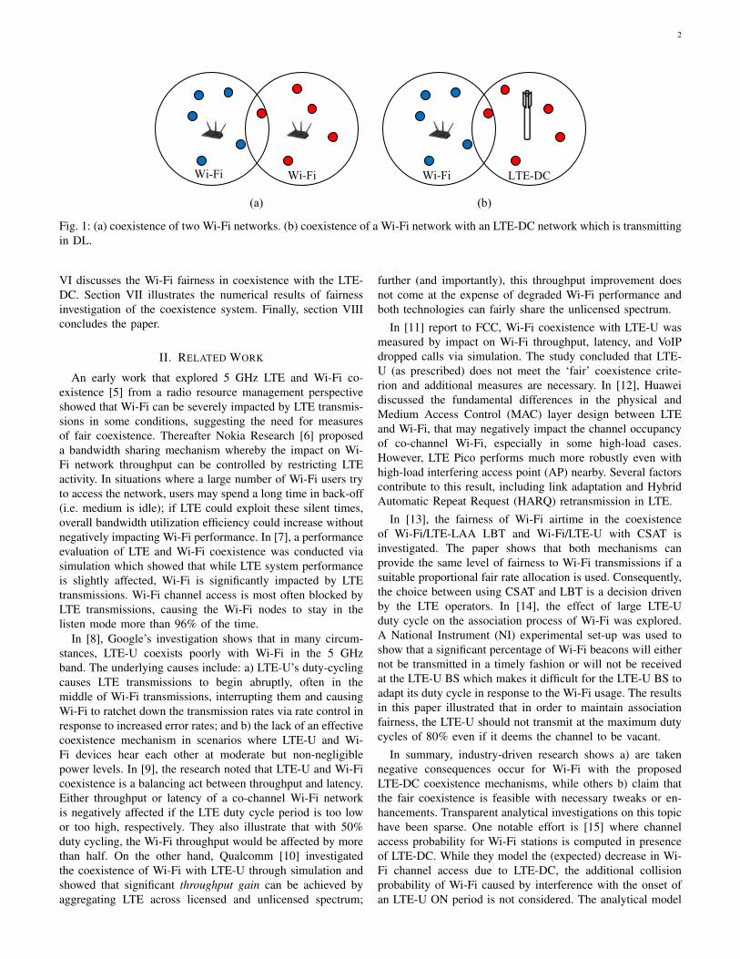
Fig. 1: (a) coexistence of two Wi-Fi networks. (b) coexistence of a Wi-Fi network with an LTE-DC network which is transmittingin DL.
VI discusses the Wi-Fi fairness in coexistence with the LTE-DC. Section VII illustrates the numerical results of fairnessinvestigation of the coexistence system. Finally, section VIIIconcludes the paper.
II. RELATED WORK
An early work that explored 5 GHz LTE and Wi-Fi co-existence [5] from a radio resource management perspectiveshowed that Wi-Fi can be severely impacted by LTE transmis-sions in some conditions, suggesting the need for measuresof fair coexistence. Thereafter Nokia Research [6] proposeda bandwidth sharing mechanism whereby the impact on Wi-Fi network throughput can be controlled by restricting LTEactivity. In situations where a large number of Wi-Fi users tryto access the network, users may spend a long time in back-off(i.e. medium is idle); if LTE could exploit these silent times,overall bandwidth utilization efficiency could increase withoutnegatively impacting Wi-Fi performance. In [7], a performanceevaluation of LTE and Wi-Fi coexistence was conducted viasimulation which showed that while LTE system performanceis slightly affected, Wi-Fi is significantly impacted by LTEtransmissions. Wi-Fi channel access is most often blocked byLTE transmissions, causing the Wi-Fi nodes to stay in thelisten mode more than 96% of the time.
In [8], Google’s investigation shows that in many circum-stances, LTE-U coexists poorly with Wi-Fi in the 5 GHzband. The underlying causes include: a) LTE-U’s duty-cyclingcauses LTE transmissions to begin abruptly, often in themiddle of Wi-Fi transmissions, interrupting them and causingWi-Fi to ratchet down the transmission rates via rate control inresponse to increased error rates; and b) the lack of an effectivecoexistence mechanism in scenarios where LTE-U and Wi-Fi devices hear each other at moderate but non-negligiblepower levels. In [9], the research noted that LTE-U and Wi-Ficoexistence is a balancing act between throughput and latency.Either throughput or latency of a co-channel Wi-Fi networkis negatively affected if the LTE duty cycle period is too lowor too high, respectively. They also illustrate that with 50%duty cycling, the Wi-Fi throughput would be affected by morethan half. On the other hand, Qualcomm [10] investigatedthe coexistence of Wi-Fi with LTE-U through simulation andshowed that significant throughput gain can be achieved byaggregating LTE across licensed and unlicensed spectrum;
further (and importantly), this throughput improvement doesnot come at the expense of degraded Wi-Fi performance andboth technologies can fairly share the unlicensed spectrum.
In [11] report to FCC, Wi-Fi coexistence with LTE-U wasmeasured by impact on Wi-Fi throughput, latency, and VoIPdropped calls via simulation. The study concluded that LTE-U (as prescribed) does not meet the ‘fair’ coexistence crite-rion and additional measures are necessary. In [12], Huaweidiscussed the fundamental differences in the physical andMedium Access Control (MAC) layer design between LTEand Wi-Fi, that may negatively impact the channel occupancyof co-channel Wi-Fi, especially in some high-load cases.However, LTE Pico performs much more robustly even withhigh-load interfering access point (AP) nearby. Several factorscontribute to this result, including link adaptation and HybridAutomatic Repeat Request (HARQ) retransmission in LTE.
In [13], the fairness of Wi-Fi airtime in the coexistenceof Wi-Fi/LTE-LAA LBT and Wi-Fi/LTE-U with CSAT isinvestigated. The paper shows that both mechanisms canprovide the same level of fairness to Wi-Fi transmissions if asuitable proportional fair rate allocation is used. Consequently,the choice between using CSAT and LBT is a decision drivenby the LTE operators. In [14], the effect of large LTE-Uduty cycle on the association process of Wi-Fi was explored.A National Instrument (NI) experimental set-up was used toshow that a significant percentage of Wi-Fi beacons will eithernot be transmitted in a timely fashion or will not be receivedat the LTE-U BS which makes it difficult for the LTE-U BS toadapt its duty cycle in response to the Wi-Fi usage. The resultsin this paper illustrated that in order to maintain associationfairness, the LTE-U should not transmit at the maximum dutycycles of 80% even if it deems the channel to be vacant.
In summary, industry-driven research shows a) are takennegative consequences occur for Wi-Fi with the proposedLTE-DC coexistence mechanisms, while others b) claim thatthe fair coexistence is feasible with necessary tweaks or en-hancements. Transparent analytical investigations on this topichave been sparse. One notable effort is [15] where channelaccess probability for Wi-Fi stations is computed in presenceof LTE-DC. While they model the (expected) decrease in Wi-Fi channel access due to LTE-DC, the additional collisionprobability of Wi-Fi caused by interference with the onset ofan LTE-U ON period is not considered. The analytical model

3
TABLE I: Glossary.
Parameter DefinitionW0 Wi-Fi minimum contention windowm Wi-Fi maximum retransmission stage
PhyH preamble with physical headerMACH MAC headerACK Acknowledgment lengthσ Wi-Fi slot timeδ propagation delay
DIFS distributed interframe spaceSIFS short interframe spaceTon LTE-DC ON periodToff LTE-DC OFF periodTC LTE-DC total cycle periodα LTE-DC duty cycleNB Wi-Fi packet data portion sizeTd Wi-Fi data portion duration
CCA Clear Channel Assessmentnw Number of Wi-Fi APs in coexistencer0 MCS0 data raterw Wi-Fi data raterl LTE-DC data ratePc,w Wi-Fi Collision Probabilityτw a Wi-Fi station transmission probability per slot
Pc,w−l Collision probability from LTE-DC to Wi-FiPc,t total collision probabilitynk maximum number of packets fit in one OFF periodLb(k) lower bound of the interval for contentionUb(k) upper bound of the interval for contentionp′h(k) probability of k-th packet hitting the ON edgeP ′s(k) successful transmission probability of k-th packetEn average number of packets fit in the OFF periodPtrw Wi-Fi transmission probabilityPsw Wi-Fi successful transmission probabilityTputw Wi-Fi throughputTputl LTE-DC throughputτwo a Wi-Fi station transmission probability per slot
in Wi-Fi only networkPc,wo Collision probability of Wi-Fi in Wi-Fi only networkTputwo Wi-Fi throughput in Wi-Fi only networkTsw expected duration of a successful packetTcw expected duration of a collided packet
in [16] for the coexistence of Wi-Fi and LTE-DC does notprovide any close form expressions (for collision probabilityand throughput) and their scenario does not conform to the realspecification of LTE-DC [4]. We hope that our contribution tothis important problem validated by actual network simulationprovides a basis for resolving some of the importance coexis-tence issues.
III. COEXISTENCE OF LTE-DC AND WI-FI: MACPROTOCOL MECHANISMS
A brief review of the Wi-Fi DCF and LTE-DC MAC ispresented, to highlight their basic differences - LTE-DC is ascheduled time division multiple access (TDMA) based whileWi-Fi is random access CSMA/CA.
A. Wi-Fi DCF
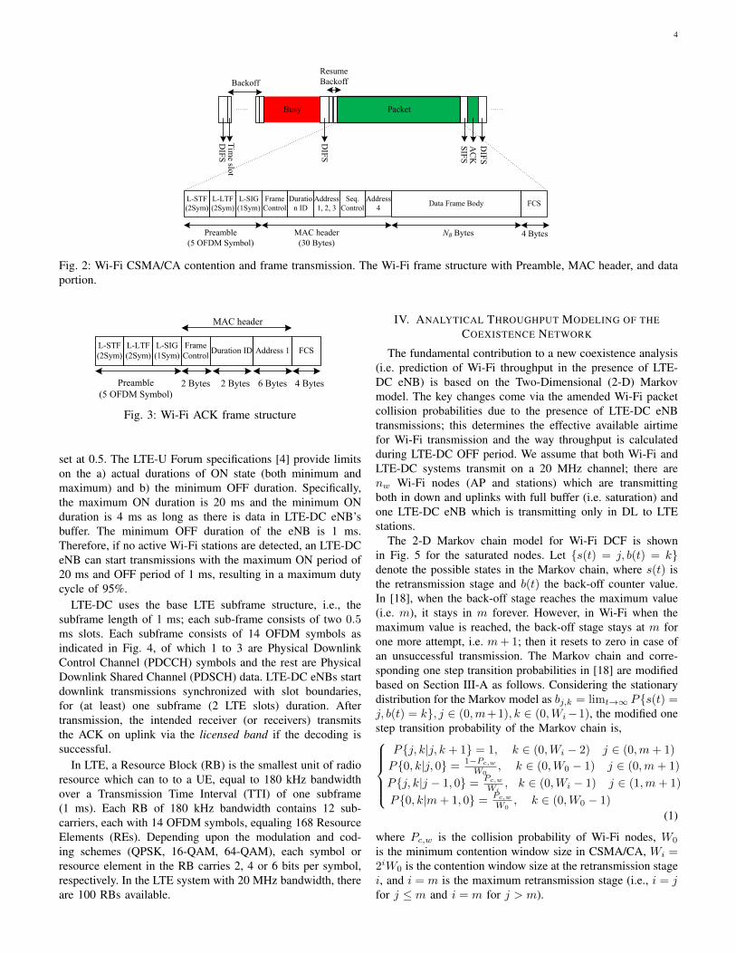
The Wi-Fi distributed coordination function (DCF) MACemploys CSMA/CA [17] as illustrated in Fig. 2. Each nodeattempting transmission must first ensure that the mediumhas been idle for a duration of DCF Interframe Spacing
(DIFS) using the energy detection (ED)3 and carrier sensing(CS)4 mechanism. When either of ED or CS is true, theclear channel assessment (CCA) flag is indicated as busy. Ifthe channel has been detected idle for DIFS duration andthe station is not accessing immediately after a successfultransmission, it transmits. Otherwise, if the channel is sensedbusy (either immediately or during the DIFS) or the station isagain seeking channel access after a successful transmission,the station persists with monitoring the channel until it ismeasured idle for a DIFS, then selects a random back-offduration (in units of slot time σ = 9µs ) and counts down.Specifically, a station selects a back-off counter uniformly atrandom in the range of [0, 2iW0 − 1] where the value of i(the back-off stage) is initialized to 0 and W0 is the minimumcontention window chosen initially. Each failed transmissiondue to packet collision5 results in incrementing the back-offstage by 1 (binary exponential back-off or BEB) and the nodecounts down from the selected back-off value. During back-off, a node decrements the counter every slot duration as longas no other transmissions are detected. If during countdowna transmission is detected, the counting is paused; nodescontinue to monitor the busy channel until it goes idle forDIFS period before the back-off countdown is resumed. Oncethe counter hits zero, the node transmits a packet. Any nodethat did not complete its countdown to zero in the currentround, carries over the back-off value and resumes countdownin the next round. Once a transmission has been completedsuccessfully, the value of i is reset to 0. The maximum valueof back-off stage i is m; it stays in m-th stage for onemore unsuccessful transmission (for a total of 2 attempts atback-off stage m). If the final transmission is unsuccessful,the node drops the packet and resets the back-off stage toi = 0. For any successful transmission, the intended receiverwill transmit an acknowledgment frame (ACK) after a ShortInterframe Spacing (SIFS) duration post reception; the ACKframe structure is shown in Fig. 3 which consists of preambleand MAC header. The ACK frame chooses the highest basicdata rate (6 Mbps, 12 Mbps, or 24 Mbps) for transmitting theMAC header which is smaller than the data rate used for datatransmission.
B. LTE-DC
LTE-DC uses a duty-cycling approach (i.e. alternating theON and OFF period, where the LTE evolved Node B (eNB)is allowed to transmit only during the ON duration) wherethe duty cycle (ratio of ON duration to one cycle period) isdetermined by perceived Wi-Fi usage at the LTE-DC eNB,using carrier sensing. During the ON period, the LTE-U eNBschedules DL transmissions to UEs, unlike Wi-Fi in whichtransmissions are governed by the CSMA/CA process. Fig. 4shows the LTE-DC transmission for the duty cycle of 0.5. If asingle Wi-Fi AP is detected, the maximum duty cycle could be
3The ability of Wi-Fi to detect any external (out-of-network) signal usingan energy detector.
4The ability of Wi-Fi to detect and decode an incoming Wi-Fi signalpreamble.
5A collision event occurs if and only if two nodes select the same back-offcounter value at the end of a DIFS period (if there is no hidden terminal).
4
Packet
Tim
e slot
DIF
S
Busy
Backoff
SIF
S
Resume Backoff
AC
KD
IFS
L-STF(2Sym)
L-LTF(2Sym)
L-SIG(1Sym)
Preamble(5 OFDM Symbol)
MAC header (30 Bytes)
Frame Control
Duration ID
Address 1, 2, 3
Seq.Control
Address 4
Data Frame Body FCS
4 BytesNB Bytes
DIF
S
Fig. 2: Wi-Fi CSMA/CA contention and frame transmission. The Wi-Fi frame structure with Preamble, MAC header, and dataportion.
2 Bytes
Frame Control
Duration ID Address 1 FCS
2 Bytes 6 Bytes 4 Bytes
MAC header
L-STF(2Sym)
L-LTF(2Sym)
L-SIG(1Sym)
Preamble(5 OFDM Symbol)
Fig. 3: Wi-Fi ACK frame structure
set at 0.5. The LTE-U Forum specifications [4] provide limitson the a) actual durations of ON state (both minimum andmaximum) and b) the minimum OFF duration. Specifically,the maximum ON duration is 20 ms and the minimum ONduration is 4 ms as long as there is data in LTE-DC eNB’sbuffer. The minimum OFF duration of the eNB is 1 ms.Therefore, if no active Wi-Fi stations are detected, an LTE-DCeNB can start transmissions with the maximum ON period of20 ms and OFF period of 1 ms, resulting in a maximum dutycycle of 95%.
LTE-DC uses the base LTE subframe structure, i.e., thesubframe length of 1 ms; each sub-frame consists of two 0.5ms slots. Each subframe consists of 14 OFDM symbols asindicated in Fig. 4, of which 1 to 3 are Physical DownlinkControl Channel (PDCCH) symbols and the rest are PhysicalDownlink Shared Channel (PDSCH) data. LTE-DC eNBs startdownlink transmissions synchronized with slot boundaries,for (at least) one subframe (2 LTE slots) duration. Aftertransmission, the intended receiver (or receivers) transmitsthe ACK on uplink via the licensed band if the decoding issuccessful.
In LTE, a Resource Block (RB) is the smallest unit of radioresource which can to to a UE, equal to 180 kHz bandwidthover a Transmission Time Interval (TTI) of one subframe(1 ms). Each RB of 180 kHz bandwidth contains 12 sub-carriers, each with 14 OFDM symbols, equaling 168 ResourceElements (REs). Depending upon the modulation and cod-ing schemes (QPSK, 16-QAM, 64-QAM), each symbol orresource element in the RB carries 2, 4 or 6 bits per symbol,respectively. In the LTE system with 20 MHz bandwidth, thereare 100 RBs available.
IV. ANALYTICAL THROUGHPUT MODELING OF THECOEXISTENCE NETWORK
The fundamental contribution to a new coexistence analysis(i.e. prediction of Wi-Fi throughput in the presence of LTE-DC eNB) is based on the Two-Dimensional (2-D) Markovmodel. The key changes come via the amended Wi-Fi packetcollision probabilities due to the presence of LTE-DC eNBtransmissions; this determines the effective available airtimefor Wi-Fi transmission and the way throughput is calculatedduring LTE-DC OFF period. We assume that both Wi-Fi andLTE-DC systems transmit on a 20 MHz channel; there arenw Wi-Fi nodes (AP and stations) which are transmittingboth in down and uplinks with full buffer (i.e. saturation) andone LTE-DC eNB which is transmitting only in DL to LTEstations.
The 2-D Markov chain model for Wi-Fi DCF is shownin Fig. 5 for the saturated nodes. Let {s(t) = j, b(t) = k}denote the possible states in the Markov chain, where s(t) isthe retransmission stage and b(t) the back-off counter value.In [18], when the back-off stage reaches the maximum value(i.e. m), it stays in m forever. However, in Wi-Fi when themaximum value is reached, the back-off stage stays at m forone more attempt, i.e. m+ 1; then it resets to zero in case ofan unsuccessful transmission. The Markov chain and corre-sponding one step transition probabilities in [18] are modifiedbased on Section III-A as follows. Considering the stationarydistribution for the Markov model as bj,k = limt→∞ P{s(t) =j, b(t) = k}, j ∈ (0,m+1), k ∈ (0,Wi−1), the modified onestep transition probability of the Markov chain is,
P{j, k|j, k + 1} = 1, k ∈ (0,Wi − 2) j ∈ (0,m+ 1)
P{0, k|j, 0} = 1−Pc,w
W0, k ∈ (0,W0 − 1) j ∈ (0,m+ 1)
P{j, k|j − 1, 0} = Pc,w
Wi, k ∈ (0,Wi − 1) j ∈ (1,m+ 1)
P{0, k|m+ 1, 0} = Pc,w
W0, k ∈ (0,W0 − 1)
(1)
where Pc,w is the collision probability of Wi-Fi nodes, W0
is the minimum contention window size in CSMA/CA, Wi =2iW0 is the contention window size at the retransmission stagei, and i = m is the maximum retransmission stage (i.e., i = jfor j ≤ m and i = m for j > m).

5
DIFS and backoff
LTE-U ON LTE-U OFF
Case 1
Case 2
Case 3
Wi-Fi Packet transmitted
Wi-Fi Packet collided
SIFS
ACK
Tp
1 42 3 5 6 7 1213148 9 1011
Data OFDM Symbols
LTE Subframe
Control OFDM Symbols
Fig. 4: LTE-DC coexisting with Wi-Fi which causes the overlap of Wi-Fi frame with LTE-DC ON edge
To simplify the calculation, we introduce the following vari-ables derived from (1) and using the Markov Chain properties:
bj,0 = Pc,wbj−1,0, 0 < j ≤ m+ 1bj,0 = P jc,wb0,0, 0 ≤ j ≤ m+ 1
b0,0 = Pc,wbm+1,0 + (1− Pc,w)∑j=m+1j=0 bj,0
, (2)
the last equation implies that,j=m+1∑j=0
bj,0 =
(1− Pm+2
c,w
1− Pc,w
)b0,0. (3)
In each retransmission stage, the back-off transition proba-bility is
bj,k =Wi − kWi
bj,0, 0 ≤ j ≤ m+ 1, 0 ≤ k ≤Wi − 1. (4)
We can derive b0,0 by the normalization condition, i.e.,m+1∑j=0
Wi−1∑k=0
bj,k = 1,
b0,0 =2
W0
((1−(2Pc,w)m+1)
(1−2Pc,w) +2m(Pm+1
c,w −Pm+2c,w )
(1−Pc,w)
)+
1−Pm+2c,w
1−Pc,w
.
(5)
Hence, the probability that a node transmits in a time slotis calculated using (3) and (5) as,
τw =
m+1∑j=0
bj,0 =
2
W0
((1−(2Pc,w)m+1)(1−Pc,w)+2m(Pm+1
c,w −Pm+2c,w )(1−2Pc,w)
(1−2Pc,w)(1−Pm+2c,w )
)+ 1
.
(6)
The collision probability of a Wi-Fi station with at least oneof the other remaining (nw − 1 Wi-Fi) stations is given by
Pc,w = 1− (1− τw)nw−1, (7)
lP
W
1 m,Wm-1m,1m,011
1 0,W0-10,10,011
1 0,W1-11,11,011
1 m',W'm'-1m',1m',0 11
lP
10,W'0-10,10,0
11
(1 )lP
10,W'1-11,11,0
111 'lP
W
lP
1 'lP
W 1 'lP
W
1 m'+1,W'm'-1m'+1,1m'+1,011
1 m'+el,W'm'-1m'+el,1m'+el,011
Retry limit (el)
1 m+1,Wm-1m+1,1m+1,011
'
)1(
0W
Pl
'
)1(
0W
Pl
'
)1(
0W
Pl
wcP,
wcP,1
wcP,
0
,1
W
Pwc
0
,1
W
P wc
0
,1
W
P wc
Fig. 5: Markov chain model for the Wi-Fi DCF with binaryexponential back-off
where Pc,w is coupled to τw.
Modeling Collision between Wi-Fi & LTE-DC
Inter-network collisions between Wi-Fi packets and LTE-DC occurs at the transition from OFF to ON period asillustrated in Case 3 of Fig. 4. The occurrence of this eventdepends on various factors: the total airtime for a Wi-Fipacket transmission equaling the sum of the Wi-Fi datapacket duration, SIFS duration, and ACK duration, denoted asTp = MACH+PhyH+Td+SIFS+ACK. We assume that anyoverlap of a Wi-Fi packet airtime Tp duration with the LTE-DCON period causes the Wi-Fi packet collision. For calculatingthe collision probability from LTE-DC to Wi-Fi, we initiallyassume that one Wi-Fi station coexisting with LTE-DC (henceno contention among the Wi-Fi network), and thereafter extendit to multiple Wi-Fi stations (to capture the Wi-Fi contention).

6
1
1
z1
2
z1
Ton
Toff
z2
TC
1 2
z1 z2
nk
znk
Tp
nk+1
znk+1
(a)
(b)
(c)
Fig. 6: Illustration: Modeling collision and successful packettransmission at the end of LTE-DC OFF period. zi is therandom backoff number and the backoff time is backoffnumber multiplied by the time slot σzi.
The probability of a collision between a Wi-Fi stationtransmission and LTE-DC downlink is calculated as
Pc,w−l =
nk+1∑k=1
P (C|H = k)p′(H = k) =
nk+1∑k=1
1
kp′h(k), (8)
where nk = bToff
Tpc is the maximum number of consecutive
Wi-Fi packets that fit within an OFF duration. H is the randomvariable for the overlap probability of the Wi-Fi packetstransmitted in OFF period with LTE-DC ON edge and Cis the collision of the last transmitted packet during OFFperiod. Thus, P (C|H = k) = 1
k is the collision probabilityreflecting the fact that only the last transmitted packet (amongk transmitted packets during the OFF period) is lost due tocollision. To compute p′(H = k) = p′h(k), that representsthe probability that the k-th packet overlaps with the LTE-DC ON edge, refer to Fig. 6 for an illustrative example.Suppose that Toff = 5 ms and packet airtime Tp = 2.3ms. In this case, the transmitting Wi-Fi station either startsfrom [0,W0 − 1] contention window or [0, 2W0 − 1] in caseof collision with the previous LTE-DC ON edge. To simplifymatters, we assume that the first packet in an OFF periodchooses the random backoff from [0, 2W0 − 1] because thelast packet in the previous OFF period is lost (with highprobability). This assumption simplifies the derivation and wewill show in the following sections that this approximation isvalid for most cases by comparing the collision probabilityfrom this theoretical model and ns-3 simulation results. Thus,the probability that the first transmitted packet in OFF periodoverlaps the next ON edge is
p′h(1) = P (Lb(1) < z1 < Ub(1)), (9)
where z1 represents the random back-off value (in terms ofnumber of contention time slots) that will lead to a packettransmission collision. σ is the time slot duration, Lb(1) =b(Toff − TP − DIFS)/σc and Ub(1) = b(Toff − DIFS)/σcare the upper and lower bounds of the collision intervalduration. The random back-off number of the first packetfollows Uniform distribution, i.e. z1 ∼ U [0, 2W0− 1]. Thus,
the probability that the first packet overlaps with the ON edgeis
p′h(1) =
0, for Lb(1) > 2W0 − 1∑2W0−1z1=Lb(1)
(1
2W0
), for 0 ≤ Lb(1) ≤ 2W0 − 1
1, for Lb(1) < 0
(10)
For the second packet onward in each OFF period, thestation chooses the random backoff uniformly from [0,W0−1]because there is no collision, i.e. first retransmission stageof Markov model. Assuming k − 1 packets are successfullytransmitted, the probability of collision for k-th packets iscalculated as:
p′h(k) =
min{2W0−1,Ub(k)}∑z1=0
p(z1)×
P (max{0, Lb(k)− z1} < Z(k) < min{Ws, Ub(k)− z1}|z1),(11)
where Lb(k) = b(Toff − k(TP + DIFS))/σc and Ub(k) =b(Toff − (k − 1)TP − kDIFS)/σc are the lower and upperbounds of interval for k > 1, Ws = (k − 1)W0 − 1 is themaximum sum of backoff numbers, and Z(k) =
∑ki=2 zi is
the sum of the backoff values from the second to the k-thpacket. Since the zi are mutually Independent and IdenticallyDistributed (IID), the Probability Density Function (PDF) ofZ(k) is the k − 1-fold convolution of uniform PDF p(zk) =1W0
.Thus, Pc,w−l which is the collision probability from LTE-
DC to Wi-Fi depends on Toff and airtime of the packet, thatmeans collision probability is a function of α = Ton
TC- the duty
cycle of LTE-DC ON period - and TC . The collision causedby LTE-DC (Pc,w−l) and collision from other Wi-Fi stations(Pc,w) is next combined to calculate the total probability ofcollision as:
Pc,t = 1− (1− Pc,w)(1− Pc,w−l)= 1− (1− τw)nw−1(1− Pc,w−l).
(12)
In order to compute the Pc,t and τw for more than onestations (nw > 1) in the network (τw depends on Pc,t, so itis a function of α and TC as well), we first jointly solve eq.(6) and (12), where for the coexistence of Wi-Fi and LTE-U,Pc,t is replaced by Pc,w in eq. (6).
The transmission probability of Wi-Fi is the probability thatat least one of the nw stations transmit a packet during a timeslot:
Ptrw = 1− (1− τw)nw . (13)
The successful transmission probability of Wi-Fi is the eventthat exactly one of the nw stations makes a transmissionattempt given that at least one of the Wi-Fi APs transmit:
Psw =nwτw(1− τw)nw−1
Ptrw. (14)
The average throughput of Wi-Fi in co-existence is calcu-lated as:
Tputw =EnTdPsw
TCrw, (15)
7
where rw is the Wi-Fi data rate. En is the average numberof successfully transmitted packets in the OFF period, andis multiplied by Td to calculate the effective duration of datatransmission in one cycle (TC). Psw in the numerator capturesthe effect of contention/collision between Wi-Fi nodes andcollision between Wi-Fi packet and LTE-DC ON edge. TheEn is calculated as:
En =
k=nk∑k=1
k(P ′s(k)− P ′s(k + 1)), (16)
where P ′s(k) is the transmission probability that a sequenceof k Wi-Fi packets are successfully transmitted in one cyclein coexistence with LTE-DC and (P ′s(k) − P ′s(k + 1)) is theprobability that exactly the k-th packet is successful.
Thus for a single station in the Wi-Fi network, the success-ful transmission probability of the first packet is calculated as:
P ′s(1) = P (0 < z1 < min{Lb(1), 2W0 − 1})
=
1, for Lb(1) > 2W0 − 1∑min{Lb(1),2W0−1}z1=0
12W0
, for 0 ≤ Lb(1) ≤ 2W0 − 1
0, for Lb(1) < 0
(17)
and the successful probability of transmission for all (k > 1)subsequent packets is calculated as:
P ′s(k) =
min{2W0−1,Ub(k)}∑z1=0
p(z1)×
P (0 < Z(k) < min{Ws, Lb(k)− z1}|z1).
(18)
For more than one Wi-Fi station in the network (nw > 1),the P ′s(k) should be re-computed; the probability that at leastone node transmits - Ptrw - must now capture the effect ofcollision with other Wi-Fi stations and the collision with LTE-DC downlink. In this case, the random number of backofftime slots zk for k-th packet as shown in Fig. 6 follows theGeometric distribution, i.e. P (zk = i) = Ptrw(1−Ptrw)i, i =0, 1, ...,∞. Hence, the total contention time slots in anygeneric OFF period Z ′(k) =
∑kj=1 zj is the sum of k IID
Geometric random variables, resulting in a negative Binomialdistribution:
P (Z ′(k) = i) =
(i+ k − 1
k − 1
)P ktrw(1− Ptrw)i, (19)
where i is the total number of contention time slots and k isthe number of transmitted packets, in the OFF period. So thesuccess probability for k packets is calculated as:
P ′s(k) = P (Z ′(k) ≤ Lb(k)− k)
=
Lb(k)−k∑i=0
(i+ k − 1
k − 1
)P ktrw(1− Ptrw)i.
(20)
The throughput of the LTE-DC considering the LTE-DCON time, duty cycle, and proportion of data symbols in eachsubframe is calculated as,
Tputl(α) =1314Ton
TCrl =
13
14αrl, (21)
TABLE II: Wi-Fi Parameters.
Parameter valuePhyH 20 µs
MACH (34 bytes)/rw µsr0 6 Mbps, 12 Mbps, 24 Mbps
ACK (14 bytes)/r0 + 20 µsδ 0.1 µsσ 9 µs
DIFS 34 µsSIFS 16 µsTd NB/rw µs
where 1314Ton is the fraction of the LTE-DC TXOP in which
the data is transmitted, i.e. 1 PDCCH symbol in a subframewith 14 OFDM symbols is considered, and rl is the LTE-LAA data rate. The effect of Wi-Fi packet collision to LTE-DC is very minor as the collision from Wi-Fi to LTE-DC justoverlap with very initial part of the LTE Ton duration becausethe TXOP of LTE is larger than Wi-Fi. From the other side,LTE has a strong physical layer to compensate for any partialoverlap/interference with it’s subframe. So, in this calculationwe assumed LTE-DC is collision free.
V. NS-3 SIMULATION AND NUMERICAL RESULTS
ns-3 is an open source network simulator supporting cred-ible simulation of protocol stacks for Wi-Fi and LTE [19].802.11a is well supported in ns-3 and for LTE-DC we ob-tained LTE signal with desired duty cycling using waveformgenerator function in ns-3. In all scenarios, both Wi-Fi andLTE-DC nodes are positioned within a small circle to ensureall nodes are exposed to each other. The full buffer traffic inUL/DL is considered and setup the flows of the network tobe UDP in order to isolate the effect of transport layer onthroughput. The simulation code for an example coexistencescenario is available for download using the current versionns-3.27, see [20]. We consider two different data rates of 6Mbps and 54 Mbps and two different TC . As already noted,constant data rates only are considered (with no rate control).The other Wi-Fi network parameters are listed in Table II.
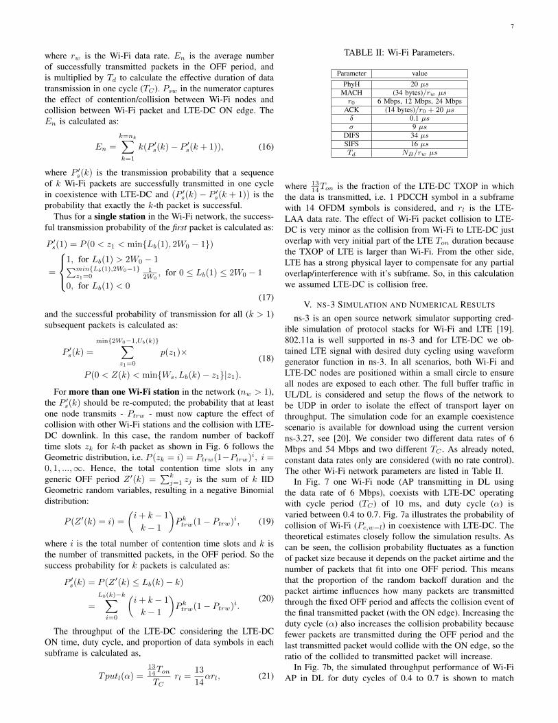
In Fig. 7 one Wi-Fi node (AP transmitting in DL usingthe data rate of 6 Mbps), coexists with LTE-DC operatingwith cycle period (TC) of 10 ms, and duty cycle (α) isvaried between 0.4 to 0.7. Fig. 7a illustrates the probability ofcollision of Wi-Fi (Pc,w−l) in coexistence with LTE-DC. Thetheoretical estimates closely follow the simulation results. Ascan be seen, the collision probability fluctuates as a functionof packet size because it depends on the packet airtime and thenumber of packets that fit into one OFF period. This meansthat the proportion of the random backoff duration and thepacket airtime influences how many packets are transmittedthrough the fixed OFF period and affects the collision event ofthe final transmitted packet (with the ON edge). Increasing theduty cycle (α) also increases the collision probability becausefewer packets are transmitted during the OFF period and thelast transmitted packet would collide with the ON edge, so theratio of the collided to transmitted packet will increase.
In Fig. 7b, the simulated throughput performance of Wi-FiAP in DL for duty cycles of 0.4 to 0.7 is shown to match
8
0 200 400 600 800 1000 1200 1400 1600 1800 20000
0.1
0.2
0.3
0.4
0.5
0.6
0.7
0.8
0.9
1
Packet Size (Bytes)
Pc,
w−
l
Sim, α=0.4, T
C=10ms
The, α=0.4, TC=10ms
Sim, α=0.5, TC=10ms
The, α=0.5, TC=10ms
Sim, α=0.7, TC=10ms
The, α=0.7, TC=10ms
Sim, α=0.8, TC=10ms
The, α=0.8, TC=10ms
(a) Probability of Collision
0 200 400 600 800 1000 1200 1400 1600 1800 20000
0.5
1
1.5
2
2.5
3
3.5
4
4.5
5
Packet Size (Bytes)
Thr
ough
put (
Mbp
s)
Sim, α=0.4, TC=10ms
The, α=0.4, TC=10ms
0.6 times Wi−Fi only Throughput
Sim, α=0.5, TC=10ms
The, α=0.5, TC=10ms
0.5 times Wi−Fi only Throughput
Sim, α=0.7, TC=10ms
The, α=0.7, TC=10ms
0.3 times Wi−Fi only Throughput
Sim, α=0.8, TC=10ms
The, α=0.8, TC=10ms
0.2 times Wi−Fi only Throughput
(b) ThroughputFig. 7: The comparison of theoretical and ns-3 simulation results for TC = 10 ms and Wi-Fi data rate of 6 Mbps. 1 Wi-Finode (the AP transmitting in DL) coexisting with LTE-DC.
theoretical model results. By increasing the duty cycle, thethroughput decreases because fewer packets are transmittedand also the probability of collision is higher. The throughputfluctuation as a function of the packet size is seen in Fig. 7a,reflecting the variability in the packet collision probabilitymentioned above. The throughput of one Wi-Fi only system(with one Wi-Fi AP, DL transmission) multiplied by the OFFcycle (1−α) is shown in the figure as the upper bound of theWi-Fi throughput if there is no interference from LTE-DC. Wi-Fi in coexistence with LTE-DC achieves a lower throughputthan the Wi-Fi only case because of interference which leadsto the collision of the last transmitted packet in OFF period.Generally, at smaller packet sizes the predicted throughput iscloser to the upper bound, as more number of packets aretransmitted in the OFF period, and hence the proportion ofcollided to transmitted packets decreases. We note that thisfluctuation in the probability of collision and throughput wasobserved in [16] but presented without further analysis ofunderlying causes.
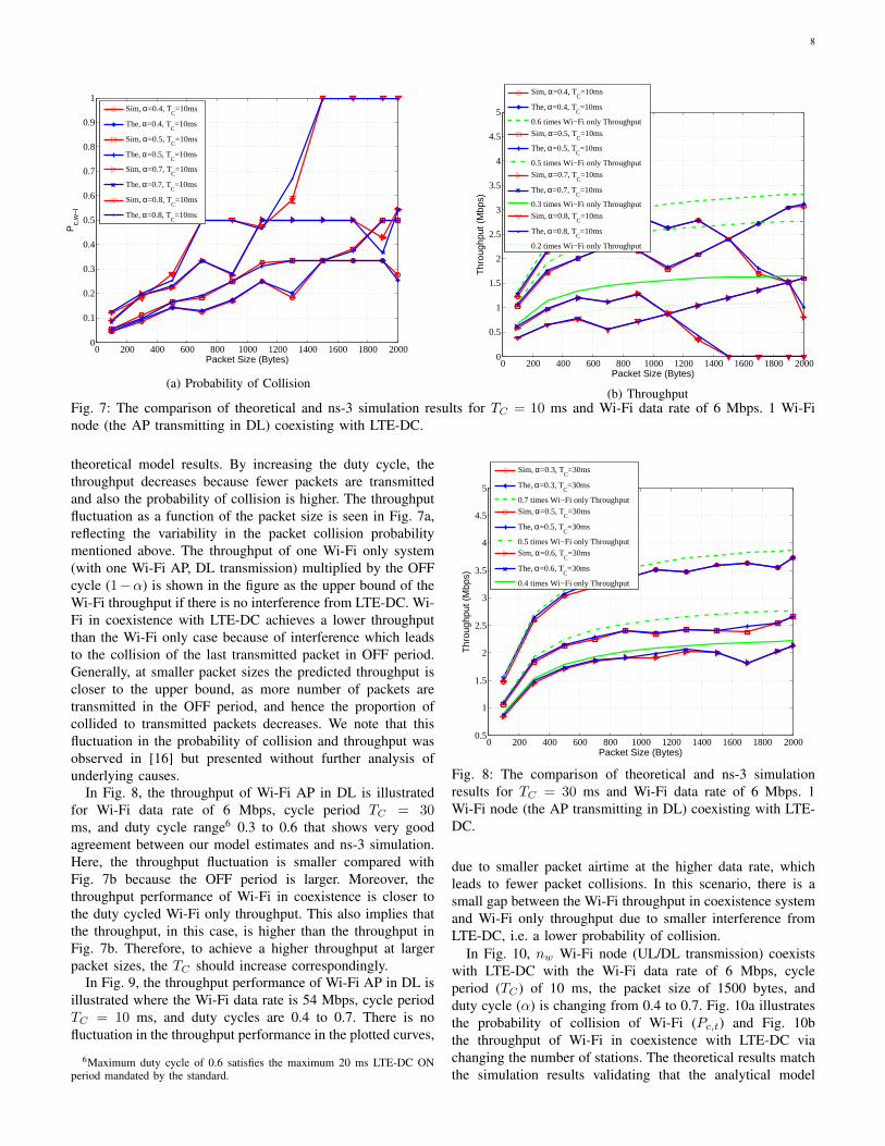
In Fig. 8, the throughput of Wi-Fi AP in DL is illustratedfor Wi-Fi data rate of 6 Mbps, cycle period TC = 30ms, and duty cycle range6 0.3 to 0.6 that shows very goodagreement between our model estimates and ns-3 simulation.Here, the throughput fluctuation is smaller compared withFig. 7b because the OFF period is larger. Moreover, thethroughput performance of Wi-Fi in coexistence is closer tothe duty cycled Wi-Fi only throughput. This also implies thatthe throughput, in this case, is higher than the throughput inFig. 7b. Therefore, to achieve a higher throughput at largerpacket sizes, the TC should increase correspondingly.
In Fig. 9, the throughput performance of Wi-Fi AP in DL isillustrated where the Wi-Fi data rate is 54 Mbps, cycle periodTC = 10 ms, and duty cycles are 0.4 to 0.7. There is nofluctuation in the throughput performance in the plotted curves,
6Maximum duty cycle of 0.6 satisfies the maximum 20 ms LTE-DC ONperiod mandated by the standard.
0 200 400 600 800 1000 1200 1400 1600 1800 20000.5
1
1.5
2
2.5
3
3.5
4
4.5
5
Packet Size (Bytes)
Thr
ough
put (
Mbp
s)
Sim, α=0.3, TC=30ms
The, α=0.3, TC=30ms
0.7 times Wi−Fi only ThroughputSim, α=0.5, T
C=30ms
The, α=0.5, TC=30ms
0.5 times Wi−Fi only ThroughputSim, α=0.6, T
C=30ms
The, α=0.6, TC=30ms
0.4 times Wi−Fi only Throughput
Fig. 8: The comparison of theoretical and ns-3 simulationresults for TC = 30 ms and Wi-Fi data rate of 6 Mbps. 1Wi-Fi node (the AP transmitting in DL) coexisting with LTE-DC.
due to smaller packet airtime at the higher data rate, whichleads to fewer packet collisions. In this scenario, there is asmall gap between the Wi-Fi throughput in coexistence systemand Wi-Fi only throughput due to smaller interference fromLTE-DC, i.e. a lower probability of collision.
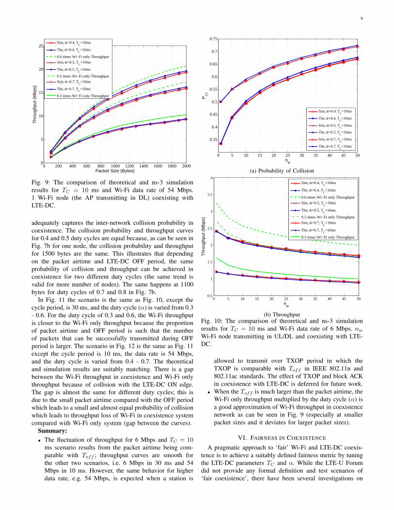
In Fig. 10, nw Wi-Fi node (UL/DL transmission) coexistswith LTE-DC with the Wi-Fi data rate of 6 Mbps, cycleperiod (TC) of 10 ms, the packet size of 1500 bytes, andduty cycle (α) is changing from 0.4 to 0.7. Fig. 10a illustratesthe probability of collision of Wi-Fi (Pc,t) and Fig. 10bthe throughput of Wi-Fi in coexistence with LTE-DC viachanging the number of stations. The theoretical results matchthe simulation results validating that the analytical model
9
0 200 400 600 800 1000 1200 1400 1600 1800 20000
5
10
15
20
25
Packet Size (Bytes)
Thr
ough
put (
Mbp
s)
Sim, α=0.4, T
C=10ms
The, α=0.4, TC=10ms
0.6 times Wi−Fi only Throughput
Sim, α=0.5, TC=10ms
The, α=0.5, TC=10ms
0.5 times Wi−Fi only Throughput
Sim, α=0.7, TC=10ms
The, α=0.7, TC=10ms
0.3 times Wi−Fi only Throughput
Fig. 9: The comparison of theoretical and ns-3 simulationresults for TC = 10 ms and Wi-Fi data rate of 54 Mbps.1 Wi-Fi node (the AP transmitting in DL) coexisting withLTE-DC.
adequately captures the inter-network collision probability incoexistence. The collision probability and throughput curvesfor 0.4 and 0.5 duty cycles are equal because, as can be seen inFig. 7b for one node, the collision probability and throughputfor 1500 bytes are the same. This illustrates that dependingon the packet airtime and LTE-DC OFF period, the sameprobability of collision and throughput can be achieved incoexistence for two different duty cycles (the same trend isvalid for more number of nodes). The same happens at 1100bytes for duty cycles of 0.7 and 0.8 in Fig. 7b.
In Fig. 11 the scenario is the same as Fig. 10, except thecycle period, is 30 ms, and the duty cycle (α) is varied from 0.3- 0.6. For the duty cycle of 0.3 and 0.6, the Wi-Fi throughputis closer to the Wi-Fi only throughput because the proportionof packet airtime and OFF period is such that the numberof packets that can be successfully transmitted during OFFperiod is larger. The scenario in Fig. 12 is the same as Fig. 11except the cycle period is 10 ms, the data rate is 54 Mbps,and the duty cycle is varied from 0.4 - 0.7. The theoreticaland simulation results are suitably matching. There is a gapbetween the Wi-Fi throughput in coexistence and Wi-Fi onlythroughput because of collision with the LTE-DC ON edge.The gap is almost the same for different duty cycles; this isdue to the small packet airtime compared with the OFF periodwhich leads to a small and almost equal probability of collisionwhich leads to throughput loss of Wi-Fi in coexistence systemcompared with Wi-Fi only system (gap between the curves).
Summary:• The fluctuation of throughput for 6 Mbps and TC = 10
ms scenario results from the packet airtime being com-parable with Toff ; throughput curves are smooth forthe other two scenarios, i.e. 6 Mbps in 30 ms and 54Mbps in 10 ms. However, the same behavior for higherdata rate, e.g. 54 Mbps, is expected when a station is
0 5 10 15 20 25 30 35 40 45 50
0.35
0.4
0.45
0.5
0.55
0.6
0.65
0.7
0.75
nw
Pc,
t
Sim, α=0.4, TC
=10ms
The, α=0.4, TC
=10ms
Sim, α=0.5, TC
=10ms
The, α=0.5, TC
=10ms
Sim, α=0.7, TC
=10ms
The, α=0.7, TC
=10ms
(a) Probability of Collision
0 5 10 15 20 25 30 35 40 45 500.5
1
1.5
2
2.5
3
3.5
4
nw
Thr
ough
put (
Mbp
s)
Sim, α=0.4, T
C=10ms
The, α=0.4, TC=10ms
0.6 times Wi−Fi only Throughput
Sim, α=0.5, TC=10ms
The, α=0.5, TC=10ms
0.5 times Wi−Fi only Throughput
Sim, α=0.7, TC=10ms
The, α=0.7, TC=10ms
0.3 times Wi−Fi only Throughput
(b) ThroughputFig. 10: The comparison of theoretical and ns-3 simulationresults for TC = 10 ms and Wi-Fi data rate of 6 Mbps. nwWi-Fi node transmitting in UL/DL and coexisting with LTE-DC.
allowed to transmit over TXOP period in which theTXOP is comparable with Toff in IEEE 802.11n and802.11ac standards. The effect of TXOP and block ACKin coexistence with LTE-DC is deferred for future work.
• When the Toff is much larger than the packet airtime, theWi-Fi only throughput multiplied by the duty cycle (α) isa good approximation of Wi-Fi throughput in coexistencenetwork as can be seen in Fig. 9 (especially at smallerpacket sizes and it deviates for larger packet sizes).
VI. FAIRNESS IN COEXISTENCE
A pragmatic approach to ‘fair’ Wi-Fi and LTE-DC coexis-tence is to achieve a suitably defined fairness metric by tuningthe LTE-DC parameters TC and α. While the LTE-U Forumdid not provide any formal definition and test scenarios of‘fair coexistence’, there have been several investigations on

10
0 5 10 15 20 25 30 35 40 45 501
1.5
2
2.5
3
3.5
4
4.5
nw
Thr
ough
put (
Mbp
s)
Sim, α=0.3, T
C=30ms
The, α=0.3, TC=30ms
0.7 times Wi−Fi only Throughput
Sim, α=0.5, TC=30ms
The, α=0.5, TC=30ms
0.5 times Wi−Fi only Throughput
Sim, α=0.6, TC=30ms
The, α=0.6, TC=30ms
0.4 times Wi−Fi only Throughput
Fig. 11: The comparison of theoretical and ns-3 simulationresults for TC = 30 ms and Wi-Fi data rate of 6 Mbps. nwWi-Fi node transmitting in UL/DL and coexisting with LTE-DC.
0 5 10 15 20 25 30 35 40 45 506
8
10
12
14
16
18
20
nw
Thr
ough
put (
Mbp
s)
Sim, α=0.4, T
C=10ms
The, α=0.4, TC=10ms
0.6 times Wi−Fi only Throughput
Sim, α=0.5, TC=10ms
The, α=0.5, TC=10ms
0.5 times Wi−Fi only Throughput
Sim, α=0.7, TC=10ms
The, α=0.7, TC=10ms
0.3 times Wi−Fi only Throughput
Fig. 12: The comparison of theoretical and ns-3 simulationresults for TC = 10 ms and Wi-Fi data rate of 54 Mbps. nwWi-Fi node transmitting in UL/DL and coexisting with LTE-DC.
this topic - notably [10] and [21] whose conclusions trend inopposite directions. In the investigation by CableLabs [21],they first established a baseline of how two Wi-Fi networksshare a channel; then, they replaced one of the Wi-Fi APswith an LTE-U eNB and repeated the tests, using variousduty cycle configurations. This parallels the 3GPP definitionof fairness for the LTE-LAA coexistence with Wi-Fi [22]whereby “LAA design should target fair coexistence withexisting Wi-Fi networks, so as to not impact Wi-Fi servicesmore than an additional Wi-Fi network on the same carrier,with respect to throughput and latency”. Hence, we use this
notion of fairness for our own investigations below.With reference to the operating scenario in Fig. 1, we
say that fairness is achieved if the appropriate metric (accessor throughput) is not worse if a Wi-Fi network is replacedby an LTE-DC network, i.e. the same access probability orthroughput is achieved for scenario in Fig. 1 (a) and Fig. 1(b). We assume that in scenario (a), there are nw stationsin each Wi-Fi network, so totally N = 2nw Wi-Fi stationsare contending for transmission; in scenario (b) the nw Wi-Fistations are replaced with an LTE-DC network in which theeNB is transmitting on downlink to the stations.
A. Wi-Fi Access Fairness
Access fairness is achieved by tuning the α or TC such thatthe probability of channel access is identical in both scenarios.In Wi-Fi only scenario with two networks and total N = 2nwWi-Fi stations (twice as the number of Wi-Fi stations in thecoexistence scenario) - Fig. 1 (a) - the probability of channelaccess is
τwo =
2
W0
((1−(2Pc,wo)m+1)(1−Pc,wo)+2m(Pm+1
c,wo −Pm+2c,wo )(1−2Pc,wo)
(1−2Pc,wo)(1−Pm+2c,wo )
)+ 1
,
Pc,wo = 1− (1− τc,wo)N−1,(22)
where using (6) in which Pc,wo is replaced by Pc,w.In the coexistence of Wi-Fi and LTE-DC, just nw Wi-Fi
stations, belonging to one Wi-Fi network, contend for channelaccess during the LTE-DC OFF period. So, as calculated inthe previous section, the probability of accessing the channelis:
τw(α, TC) =
2
W0
((1−(2Pc,t)m+1)(1−Pc,t)+2m(Pc,t
m+1−Pc,tm+2)(1−2Pc,t)
(1−2Pc,t)(1−Pc,tm+2)
)+ 1
,
Pc,t(α, TC) = 1− (1− Pc,w)(1− Pc,w−l),(23)
where τw is a function of α and TC . This follows from (6)with Pc,w replaced by the Pc,t. To achieve access fairness, wethus propose to
minα|τw(α, TC)− τwo| ,
s.t. 0 < α < 1,(24)
where the TC range depend on the maximum and minimumvalues of ON and OFF period of LTE-DC, per the LTE-Ustandard.
B. Wi-Fi Throughput Fairness
In coexistence, the Wi-Fi throughput (15) depends on theLTE-DC parameters α and TC , which can be tuned to achieveWi-Fi throughput. For a given TC , we optimize α to achievethroughput fairness. For the two Wi-Fi networks with N =

11
2nw contending Wi-Fi stations, the total throughput in Wi-Fionly is calculated as:
Tputwo =PtrPsTd
(1− Ptr)σ + Ptr(1− Ps)Tcw + PtrPsTswrw,
Ptr = 1− (1− τwo)N ,
Ps =Nτwo(1− τwo)N−1
Ptr,
Tsw = MACH + PhyH + Td + SIFS + δ + ACK + DIFS + δ
Tcw = Tsw(25)
where the τwo and collision probability Pwo is given byEq (22). So, in the coexistence network nw Wi-Fi stations,belonging to one Wi-Fi network, contend for channel accessduring the LTE-DC OFF period. We propose to tune α of LTE-DC such that the throughput fairness is achieved as follows:
Tputw(α, TC) =Tputwo
2, (26)
i.e., the optimization problem to achieve Wi-Fi throughputfairness is
minα
∣∣∣∣Tputw(α, TC)− Tputwo2
∣∣∣∣s.t. 0 < α < 1.
(27)
VII. COEXISTENCE FAIRNESS: NUMERICAL RESULTS
The two different notions of fairness in coexistence of Wi-Fi and LTE-DC network are investigated for three differentscenarios: A) TC = 10 ms with rw = 6 Mbps, B) TC = 30ms with rw = 6 Mbps, and C) TC = 10 ms with rw = 54Mbps. The packet size is kept fixed at 1500 bytes and the LTEduty cycle parameter α is tracked as a function of the numberof stations to achieve the desired fairness metric. The fairnessproblems in eq. (24) and (27) is numerically solved using theMATLAB numerical solver. Since we already validated theanalytical model, we are just using the numerical results forinvestigating the fairness.
A. Wi-Fi Access Fairness
In access fairness, the LTE duty cycle (α) is chosen such thatthe same access probability of Wi-Fi in coexistence and Wi-Fionly network is achieved. Fig. 13 illustrates the optimized αversus the number of Wi-Fi stations, for the three differentscenarios. In all of these scenarios, α could be very largeand the LTE-DC gets most of the airtime. So, the availableairtime and correspondingly the throughput of Wi-Fi is verysmall. This fact implies that by achieving the access fairness,the LTE-DC is very unfair to Wi-Fi regarding airtime andthroughput.
B. Wi-Fi Throughput Fairness
Fig. 14 shows the optimized α for throughput fairnessfor same scenarios as Fig. 13. For one Wi-Fi client anddownlink, scenario A requires the smallest LTE-DC duty cyclefor achieving the fairness, while for scenario B, α is the largest.This is because the packet airtime is comparable with the
0 5 10 15 20 25 30 35 40 45 500.2
0.3
0.4
0.5
0.6
0.7
0.8
0.9
1
nw
α
TC=10 ms, r
w=6 Mbps − Scenario A
TC=30 ms, r
w=6 Mbps − Scenario B
TC=10 ms, r
w=54 Mbps − Scenario C
Fig. 13: The optimized duty cycle (α) to achieve the accessfairness vs. different number of stations - the Wi-Fi packetsize is 1500 bytes.
0 5 10 15 20 25 30 35 40 45 50
0.35
0.4
0.45
0.5
0.55
0.6
0.65
nw
α
TC=10 ms, r
w=6 Mbps − Scenario A
TC=30 ms, r
w=6 Mbps − Scenario B
TC=10 ms, r
w=54 Mbps − Scenario C
Fig. 14: The optimized duty cycle (α) to achieve the through-put fairness vs. different number of stations - the Wi-Fi packetsize is 1500 bytes.
LTE-DC OFF duration, i.e. the OFF duration is very small inscenario A. As the number of stations increases, the duty cycleincreases which implies that Wi-Fi - Wi-Fi coexistence causesmore throughput drop than the LTE-DC. Hence, LTE-DC canuse a larger portion of the airtime and still be fair to Wi-Ficompared with another Wi-Fi. Fig. 15 shows the throughputof Wi-Fi when fairness is achieved - note that the curve with2nw node and rw = 6 Mbps is the throughput for scenario Aand B, and the curve with 2nw node and rw = 54 Mbps isthe throughput for scenario C.
Summary:• Access fairness results in a very large optimal LTE-DC
duty cycle which implies a very small throughput for Wi-Fi.
• In throughput fairness, as the number of Wi-Fi nodes

12
0 5 10 15 20 25 30 35 40 45 500
2
4
6
8
10
12
14
16
nw
Thr
ough
put (
Mbp
s)
Throughput Fair, half throughput of 2nw Wi−Fi only, r
w=6 Mbps − Scenario A, B
Throughput Fair, half throughput of 2nw Wi−Fi only, r
w=54 Mbps − Scenario C
Fig. 15: The Wi-Fi throughput (half throughput, i.e. Tputwo
2 ,which is calculated from (25)) when the throughput fairnessis achieved for the Wi-Fi packet size of 1500 bytes.
increases, the Wi-Fi network requires smaller airtime(larger α) to achieve fairness. This implies that for dutycycle value α = 0.5, Wi-Fi could achieve a higherthroughput in coexistence with LTE-DC than anothersimilar size Wi-Fi network.
• The LTE-U Forum specifications [23] recommend thatLTE-U share the channel with one full buffer Wi-Fi link(one Wi-Fi network) by tuning its duty cycle below 0.5.For nw = 1, our results show that throughput fairnesssatisfies the LTE-U Forum condition but for n ≥ 5, thiscondition is not satisfied.
The above results are taken together suggest that the fairnessmetrics considered may not be sufficient; thus, a deeperinvestigation of this matter is necessary and is deferred tofuture work.
VIII. CONCLUSION
In this work, we first presented a new analytical model forcomputing the throughput performance of Wi-Fi in coexistencewith LTE-DC. The analytical results suitably match the ns-3 simulation results, validating the proposed model. Further,access and throughput fairness of Wi-Fi in coexistence with theLTE-DC network are investigated as a function of the LTE-DCduty cycle. The results indicate that in most of the scenariosconsidered: by increasing the number of Wi-Fi nodes, theWi-Fi network in coexistence with LTE-DC with α = 0.5achieves a higher throughput than coexisting with anothersimilar Wi-Fi network. Several directions of future work areindicated: an analytical model for LTE-U with CSAT, and adeeper investigation into coexistence fairness between Wi-Fiand LTE-U.
ACKNOWLEDGMENT
The authors would like to thank Drs. Monisha Ghosh andVanlin Sathya (U Chicago) for helpful discussions.
REFERENCES
[1] LTE-U Forum, “http://www.lteuforum.org/.”[2] FCC, “Revision of Part 15 of the Commission’s Rules to Permit
Unlicensed National Information Infrastructure (U-NII) Devices in the5GHz Band,” in Federal Communications Commission, Feb 2013.
[3] ETSI, “LTE; Evolved Universal Terrestrial Radio Access (E-UTRA);Physical layer procedures,” ETSI TS 136 213, V13.1.1, Release 13, May2016.
[4] LTE-U Forum, “LTE-U CSAT Procedure TS V1.0,” Oct. 2015.[5] F. M. Abinader, et al, “Enabling the coexistence of LTE and Wi-Fi in
unlicensed bands,” IEEE Communications Magazine, vol. 52, no. 11,pp. 54–61, Nov 2014.
[6] T. Nihtila, et al, “System performance of LTE and IEEE 802.11 coex-isting on a shared frequency band,” in IEEE Wireless Communicationsand Networking Conference (WCNC), April 2013, pp. 1038–1043.
[7] A. M. Cavalcante, et al, “Performance Evaluation of LTE and Wi-FiCoexistence in Unlicensed Bands,” in IEEE 77th Vehicular TechnologyConference (VTC Spring), June 2013, pp. 1–6.
[8] N. Jindal and D. Breslin, “LTE and Wi-Fi in Unlicensed Spectrum:A Coexistence Study,” in Google white paper, Feb 2013. [Online].Available: https://ecfsapi.fcc.gov/file/60001078145.pdf
[9] J. Padden, “Wi-Fi vs. Duty Cycled LTE: A Balancing Act,”in Article from CableLabs, Dec. 2014. [Online]. Available: http://www.cablelabs.com/wi-fi-vs-duty-cycled-lte/
[10] “Qualcomm Research LTE in Unlicensed Spectrum: Harmonious Coex-istence with Wi-Fi,” in Technical Report from Qualcomm TechnologiesInc., June 2014.
[11] C. Szymanski, “ET Docket No. 15-105: Office of Engineering andTechnology and Wireless Telecommunications Bureau Seek Informationon Current Trends in LTE-U and LAA Technology,” in Broadcom Reportto FCC, June 2015.
[12] “U-LTE: Unlicensed Spectrum Utilization of LTE,” in HuaweiWhitepaper, 2014. [Online]. Available: www.researchgate.net/file.PostFileLoader.html?id=58b9e5f6404854444761f1dbassetKey=AS3A467944359632896401488578037600
[13] C. Cano and D. J. Leith, “Unlicensed LTE/WiFi coexistence: Is LBTinherently fairer than CSAT?” in IEEE International Conference onCommunications (ICC), May 2016, pp. 1–6.
[14] V. Sathya, M. Mehrnoush, M. Ghosh, and S. Roy, “Association fairnessin Wi-Fi and LTE-U coexistence,” in arXiv, January 2018. [Online].Available: https://arxiv.org/abs/1801.03817
[15] A. Babaei, J. Andreoli-Fang, and B. Hamzeh, “On the impact of LTE-Uon Wi-Fi performance,” in IEEE 25th Annual International Symposiumon Personal, Indoor, and Mobile Radio Communication (PIMRC), Sept2014, pp. 1621–1625.
[16] A. Abdelfattah and N. Malouch, “Modeling and Performance Analysisof Wi-Fi Networks Coexisting with LTE-U,” in INFOCOM, May 2017.
[17] “Wireless LAN Medium Access Control (MAC) and Physical Layer(PHY) specifications,” IEEE Std 802.11-2012, 2012.
[18] G. Bianchi, “Performance Analysis of the IEEE 802.11 Distributed Co-ordination Function,” IEEE Journal of Selected Area Communications,vol. 18, no. 3, pp. 535–547, Sep. 2006.
[19] “ns-3 Network Simulator,” https://www.nsnam.org.[20] “ns-3 Wi-Fi and LTE-DC Coexistence Scenario Example,”
https://depts.washington.edu/funlab/projects/spectrum-sharing/.[21] J. Andreoli-Fang, “Wi-Fi vs. Duty Cycled LTE-U: In-Home
Testing Reveals Coexistence Challenges,” in Article fromCableLabs, Nov. 2015. [Online]. Available: https://www.cablelabs.com/wi-fi-vs-duty-cycled-lte-u-in-home-testing-reveals-coexistence-challenges/
[22] 3GPP, “3rd Generation Partnership Project; Technical SpecificationGroup Radio Access Network; Study on Licensed-Assisted Access toUnlicensed Spectrum;(Release 13),” 3GPP TR 36.889, V13.0.0, June2015.
[23] LTE-U Forum, “LTE-U SDL Coexistence Specifications V1.3,” Oct.2015.
![OdakyuAndroid t Google play] Wi-Fi Android ios t App Store] Wi-Fi [App Store] [iPhone Profile) Wi-Fi # —E Odakyu Odakyu Free Wi-Fi Android [Google play] WI-Fi Android [App Wi-Fi](https://img.dokumen.tips/doc/110x75/5fcc31f69b77e950d81a9828/android-t-google-play-wi-fi-android-ios-t-app-store-wi-fi-app-store-iphone.jpg)


![2 Pilih [Wi-Fi function (Fungsi Wi-Fi)]](https://img.dokumen.tips/doc/110x75/587653b01a28ab135e8b9be3/2-pilih-wi-fi-function-fungsi-wi-fi.jpg)