Embed Size (px)
Citation preview

Modeling magnetic photonic crystals with lossy ferritesusing an efficient complex envelope alternating-
direction-implicit finite-difference time-domain methodGurpreet Singh,1,* Eng Leong Tan,1 and Zhi Ning Chen2
1School of Electrical and Electronic Engineering, Nanyang Technological University, Singapore 6397982Institute for Infocomm Research, Singapore 138632
*Corresponding author: [email protected]
Received March 1, 2011; accepted March 11, 2011;posted March 17, 2011 (Doc. ID 143471); published April 15, 2011
In this Letter, we present an efficient complex-envelope alternating-direction-implicit finite-difference time-domain(CE-ADI-FDTD) method for the transient analysis of magnetic photonic crystals with lossy ferrites. The proposedCE-ADI-FDTD method is generally formulated for a saturated ferrite with anisotropic permittivity tensor and ferriteloss. Auxiliary differential equations for modeling saturated ferrite and Maxwell’s curl equations are first cast into afirst-order differential system in a CE form. Then, by using an efficient ADI splitting formulas, the proposed CE-ADI-FDTD method is attained in a very concise form with few and simple right-hand side terms. The performance of theproposed method is validated and compared with the explicit FDTD method. © 2011 Optical Society of AmericaOCIS codes: 000.4430, 230.3810.
Periodic structures with anisotropic materials can exhibitdispersion relations that support unique effects in electro-magnetic wave propagation. For example, a magneticphotonic crystal (PhC) with unit cells composed of a fer-rite layer and twomisaligned anisotropic dielectric layerscan display an asymmetric dispersion relation with a sta-tionary inflection point (SIP) [1]. At the SIP frequency,electromagnetic wave propagates as a slow wave withvanishing group velocity and amplitude growth in a parti-cular direction, and as a normal wave in the opposite di-rection.Nonmagnetic PhCswith unit cells composedof anisotropic layer and two misaligned anisotropic dielectriclayers can display symmetric dispersion relations such asdegenerate band edges (DBE) and split band edges (SBE)[2]. For both these dispersion relations, an electromag-netic wave can propagate with vanishing group velocityand amplitude growth at frequencies near the band edge.In addition, for the SBE PhC, good transmittance can beachieved regardless of incident wave polarization.Recently, the complex-envelope alternating-direction-
implicit finite-difference time-domain (CE-ADI-FDTD)method was proposed for transient analysis of nonmag-netic DBE and SBE PhCs [3]. The CE-ADI-FDTD methodis a suitable numerical method as it adopts the ADI algo-rithm [4] to remove the Courant-limit time-step bound,that can be computational demanding when highly re-fined grids are used for modeling sharp field variationsin the PhC. The CE-ADI-FDTD method further adoptsa CE [5,6] formulation that has low numerial dispersionerror near the carrier frequency even for large Courantnumbers. The presence of very narrow bandwidth reso-nances in the PhC thus allows the CE-ADI-FDTD methodto operate at large Courant numbers with reasonable ac-curacy. In this Letter, we present an efficient CE-ADI-FDTD method for the transient analysis of magneticPhCs with lossy ferrites. The proposed method can po-tentially be used for efficient transient analysis of opticaldevices composed of lossy magnetic PhCs such as cav-ities [7], circulators, and isolators [8].
Consider the following set of equations that describewave propagation in a saturated ferrite, under small sig-nal condition and z directed dc bias magnetic field [9]
∂E∂t
¼ κ∇ ×H; ð1Þ
∂H∂t
¼ −1μ0
∇ × E −∂M∂t
; ð2Þ
∂M∂t
¼ −γμ0ðMsz ×H þM ×H0zÞ þαMs
�Msz ×
∂M∂t
�;
ð3Þwhere E, H, and M are the time-varying electric field,magnetic field, and magnetization vectors, respectively.Ms and H0 denote the magnitudes of saturation magne-tization and dc biasing magnetic field, respectively. γ isthe gyromagnetic ratio and α is the loss constant. κ repre-sents the inverse permittivity tensor (κ ¼ ϵ−1) with ele-ments κxz, κzx, κyz, and κzy equal to zero. Assum-ing plane wave propagation along the z direction,Eqs. (1)–(3) reduce to six equations that can be ex-pressed as a first-order differential system in the CE form
∂ ~U∂t
¼ ð−jωcI þMÞ~U; ð4Þin which field envelope vector ~U is
~U ¼ ½ ~Ex~Ey
~Hx~Hy
~Mx~My �T ; ð5Þ
ωc is the carrier angular-frequency, I is the identitymatrix, and M is the matrix comprising the differentialoperator. The field components can be obtained fromtheir corresponding envelopes using the relationU ¼ ℜf~Uejωctg.
By splitting the matrix ð−jωcI þMÞ into two matricesand using them in the fundamental ADI splitting formulas[4], the proposed CE-ADI formulation that efficientlyupdates ~U can be attained in a compact form as
1494 OPTICS LETTERS / Vol. 36, No. 8 / April 15, 2011
0146-9592/11/081494-03$15.00/0 © 2011 Optical Society of America

Sub-step 1:Vn ¼ G~Un− Vn−1
2; ð6Þ�I −
Δt4
A
�~Unþ1
2 ¼ Vn; ð7Þ
Sub-step 2:Vnþ12 ¼ G~Unþ1
2 − Vn; ð8Þ�I −
Δt4B
�~Unþ1 ¼ Vnþ1
2; ð9Þ
where V is an auxiliary vector denoted as
V ¼ ½ ex ey hx hy mx my �T ; ð10Þand A, B, and G are 6 × 6 matrices selected as
A ¼
26666666666664
0 0κxy ∂
∂z12þjωcΔt
8
0 0 0
0 0κyy ∂
∂z12þjωcΔt
8
0 0 0
0 p11μ0
∂
∂z 0 0 0 0
0 p21μ0
∂
∂z 0 0 0 0
0 p31μ0
∂
∂z 0 0 0 0
0 p41μ0
∂
∂z 0 0 0 0
37777777777775; ð11Þ
B ¼
26666666666664
0 0 0 −κxx ∂
∂z12þjωcΔt
8
0 0
0 0 0 −κyx ∂
∂z12þjωcΔt
8
0 0
−p12μ0
∂
∂z 0 0 0 0 0
−p22μ0
∂
∂z 0 0 0 0 0
−p32μ0
∂
∂z 0 0 0 0 0
−p42μ0
∂
∂z 0 0 0 0 0
37777777777775; ð12Þ
G ¼24�
112þjωcΔt
8
�I 0
0 P
35: ð13Þ
In Eq. (13), matrices 0, I, and P are the null matrix, the2 × 2 identity matrix, and the 4 × 4 matrix
P ¼
266664
12 þ Δtξ1
4Δtξ24 −
Δtξ34 −
Δtξ44
−Δtξ24
12 þ Δtξ1
4Δtξ44 −
Δtξ34
−Δtξ54 −
Δtξ24
12 þ Δtξ6
4Δtξ44
Δtξ24 −
Δtξ54 −
Δtξ44
12 þ Δtξ6
4
377775−1
; ð14Þ
respectively. The elements ξ in the matrix P are
ξ1 ¼jωc
2þ ωmα2ðα2 þ 1Þ ; ξ2 ¼
ωm
2ðα2 þ 1Þ ;
ξ3 ¼ω0α
2ðα2 þ 1Þ ; ξ6 ¼jωc
2þ ω0α2ðα2 þ 1Þ ;
ξ4 ¼ω0
2ðα2 þ 1Þ ; ξ5 ¼ωmα
2ðα2 þ 1Þ ;
with ωm ¼ γμ0Ms and ω0 ¼ γμ0H0. plm in Eqs. (11) and(12) denote the elements of matrix P.
The actual numerical update of components of ~U isnext discussed. For spatial discretization, we assume auniform grid of cell size Δz with staggered ~E and ~Hand collocated ~H and ~M field positions. Consider theSubstep 1 as an example.
1. Auxiliary updating of Vn in Eq. (6)
exnk ¼ 112 þ jωcΔt
8
~Exnk − ex
n−12
k ; ð15Þ
eynk ¼ 112 þ jωcΔt
8
~Eynk − ey
n−12
k ; ð16Þ
2664hxhymx
my
3775n
kþ12
¼ P
2664
~Hx~Hy~Mx~My
3775n
kþ12
−
2664hxhymx
my
3775n−1
2
kþ12
: ð17Þ
2. Implicit updating of ~Eynþ1
2k in Eq. (7)
−
p11κyyΔt2
16μ0Δz2
12 þ jωcΔt
8
! ~Ey
nþ12
k−1 þ ~Eynþ1
2kþ1
!þ 1þ 2
p11κyyΔt2
16μ0Δz2
12 þ jωcΔt
8
!!
× ~Eynþ1
2k ¼ eynk þ
κyyΔt4Δz
12 þ jωcΔt
8
!�hx
nkþ1
2− hx
nk−1
2
�: ð18Þ
3. Explicit updating of the remaining fields in Eq. (7)
~Hxnþ1
2
kþ12¼ hx
nkþ1
2þ�p11Δt4μ0Δz
��~Ey
nþ12
kþ1 −~Ey
nþ12
k
�; ð19Þ
~Hynþ1
2
kþ12¼ hy
nkþ1
2þ�p21Δt4μ0Δz
��~Ey
nþ12
kþ1 −~Ey
nþ12
k
�; ð20Þ
~Mxnþ1
2
kþ12¼ mx
nkþ1
2þ�p31Δt4μ0Δz
��~Ey
nþ12
kþ1 −~Ey
nþ12
k
�; ð21Þ
~Mynþ1
2
kþ12¼ my
nkþ1
2þ�p41Δt4μ0Δz
��~Ey
nþ12
kþ1 −~Ey
nþ12
k
�; ð22Þ
~Exnþ1
2k ¼ exnk þ
� κxyΔt4Δz
12 þ jωcΔt
8
��~Hx
nþ12
kþ12− ~Hx
nþ12
k−12
�: ð23Þ
Upon the update of auxiliary fields with Eqs. (15)–(17),
the implicit update of intermediate field ~Eynþ1
2k is
performed by solving a system of linear equations thatis formed by Eq. (18), with tridiagonal matrix coefficient.Notice that Eq. (18) has few and simple right-hand side(RHS) terms, which is a feature of the efficient ADI split-ting formulas [4] using auxiliary variables. This makes theproposed method easy and efficient to implement. Upon
the update of ~Eynþ1
2k , the remaining intermediate fields
can be updated explicitly with Eqs. (19)–(23). A similar
April 15, 2011 / Vol. 36, No. 8 / OPTICS LETTERS 1495
updated procedure can be deduced for Substep 2 to com-plete the update of ~Unþ1.Next, we demonstrate the proposed CE-ADI-FDTD
method for the efficient modeling of lossy magneticPhCs. Consider a N ¼ 16 periodically stacked array withunit cells, each composed of two anisotropic dielectriclayers A1 and A2 and one ferrite layer F (layer sequenceF -A2-A1 toward þz direction). Layers A1 and A2 arecharacterized by free space permeability, and thefollowing permittivity tensor with ϵA1 ¼ ϵA2 ¼ 31:39,δA1 ¼ δA2 ¼ 13:61, ϕA1 ¼ 0°, and ϕA2 ¼ 45°:
ϵ ¼ ϵ0
24 ϵA þ δA cosð2ϕAÞ δA sinð2ϕAÞ 0
δA sinð2ϕAÞ ϵA − δA cosð2ϕAÞ 00 0 ϵzz
35:ð24Þ
Layer F is characterized by scalar permittivity of 14:5ϵ0and ferrite parameters of ωm ¼ 3:5441 × 1010 rad=s andω0 ¼ 9:4178 × 1010 rad=s. For a lossy ferrite case,α ¼ 0:01. The layer thicknesses are LA1 ¼ LA2 ¼ 1mmand LF ¼ 0:25mm. The band diagram and transmittanceof the magnetic PhC is shown in Fig. 1 for a lossless case(α ¼ 0). The figure shows that the SIP and the near unittransmittance overlap in the region of 10:65GHz.The proposed CE-ADI-FDTDmethod is next used to ef-
ficiently compute the time-average field intensity jEj2 in-side the magnetic PhC. The simulations are performedwith a uniform cell size of Δz ¼ 0:01mm, time step sizeofΔt ¼ CFLN 0:98Δz
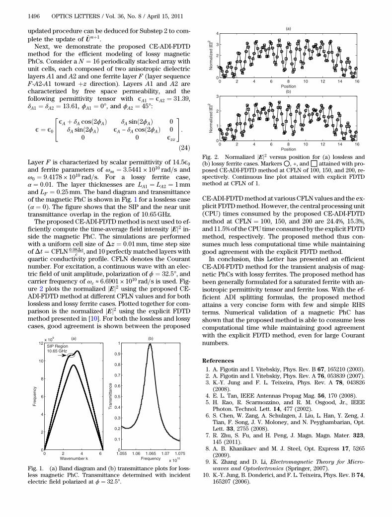
c , and 10 perfectly matched layers withquartic conductivity profile. CFLN denotes the Courantnumber. For excitation, a continuous wave with an elec-tric field of unit amplitude, polarization of ϕ ¼ 32:5°, andcarrier frequency of ωc ≈ 6:6901 × 1010 rad=s is used. Fig-ure 2 plots the normalized jEj2 using the proposed CE-ADI-FDTD method at different CFLN values and for bothlossless and lossy ferrite cases. Plotted together for com-parison is the normalized jEj2 using the explicit FDTDmethod presented in [10]. For both the lossless and lossycases, good agreement is shown between the proposed
CE-ADI-FDTDmethod at various CFLN values and the ex-plicit FDTDmethod. However, the central processing unit(CPU) times consumed by the proposed CE-ADI-FDTDmethod at CFLN ¼ 100, 150, and 200 are 24.4%, 15.3%,and 11.5%of theCPU time consumedby the explicit FDTDmethod, respectively. The proposed method thus con-sumes much less computational time while maintaininggood agreement with the explicit FDTD method.
In conclusion, this Letter has presented an efficientCE-ADI-FDTD method for the transient analysis of mag-netic PhCs with lossy ferrites. The proposed method hasbeen generally formulated for a saturated ferrite with an-isotropic permittivity tensor and ferrite loss. With the ef-ficient ADI splitting formulas, the proposed methodattains a very concise form with few and simple RHSterms. Numerical validation of a magnetic PhC hasshown that the proposed method is able to consume lesscomputational time while maintaining good agreementwith the explicit FDTD method, even for large Courantnumbers.
References
1. A. Figotin and I. Vitebskiy, Phys. Rev. B 67, 165210 (2003).2. A. Figotin and I. Vitebskiy, Phys. Rev. A 76, 053839 (2007).3. K.-Y. Jung and F. L. Teixeira, Phys. Rev. A 78, 043826
(2008).4. E. L. Tan, IEEE Antennas Propag Mag. 56, 170 (2008).5. H. Rao, R. Scarmozzino, and R. M. Osgood, Jr., IEEE
Photon. Technol. Lett. 14, 477 (2002).6. S. Chen, W. Zang, A. Schulzgen, J. Liu, L. Han, Y. Zeng, J.
Tian, F. Song, J. V. Moloney, and N. Peyghambarian, Opt.Lett. 33, 2755 (2008).
7. R. Zhu, S. Fu, and H. Peng, J. Magn. Magn. Mater. 323,145 (2011).
8. A. B. Khanikaev and M. J. Steel, Opt. Express 17, 5265(2009).
9. K. Zhang and D. Li, Electromagnetic Theory for Micro-
waves and Optoelectronics (Springer, 2007).10. K.-Y. Jung, B. Donderici, and F. L. Teixeira, Phys. Rev. B 74,
165207 (2006).
0 2 4 60
2
4
6
8
10
12x 10
9 (a)
Wavenumber k
Fre
quen
cy
1.055 1.06 1.065 1.07 1.075
x 1010
0
0.1
0.2
0.3
0.4
0.5
0.6
0.7
0.8
0.9
1
Frequency
Tra
nsm
ittan
ce
(b)
SIP Region10.65 GHz
Fig. 1. (a) Band diagram and (b) transmittance plots for loss-less magnetic PhC. Transmittance determined with incidentelectric field polarized at ϕ ¼ 32:5°.
0 2 4 6 8 10 12 14 160
1
2
3
4
Position
Nor
mal
ized
|E|2
(a)
0 2 4 6 8 10 12 14 160
1
2
3
Position
Nor
mal
ized
|E|2
(b)
Fig. 2. Normalized jEj2 versus position for (a) lossless and(b) lossy ferrite cases. Markers ○, +, and□ attained with pro-posed CE-ADI-FDTD method at CFLN of 100, 150, and 200, re-spectively. Continuous line plot attained with explicit FDTDmethod at CFLN of 1.
1496 OPTICS LETTERS / Vol. 36, No. 8 / April 15, 2011


![Ферритовые сердечники - Coretech2012].pdfCOSMO FERRITES has a leading position in inside soft ferrites market. It pioneered the exports of Soft Ferrites from India](https://img.dokumen.tips/doc/110x75/5f0c57bc7e708231d434ed9b/-2012pdf-cosmo-ferrites-has-a-leading.jpg)


![Ferrites Brochure 46[1]](https://img.dokumen.tips/doc/110x75/5451c66baf795908308b4ac2/ferrites-brochure-461.jpg)


