Embed Size (px)
Citation preview

Object Libraries
Modeling Data User's Guide
Version 6.6.0 / April 2013

1
Copyright © 2013, by OPEN CASCADE S.A.S. PROPRIETARY RIGHTS NOTICE: All rights reserved. Verbatim copying and distribution of this entire document are permitted worldwide, without royalty, in any medium, provided the copyright notice and this permission notice are preserved. The information in this document is subject to change without notice and should not be construed as a commitment by OPEN CASCADE S.A.S. OPEN CASCADE S.A.S. assures no responsibility for any errors that may appear in this document. The software described in this document is furnished under a license and may be used or copied only in accordance with the terms of such a license. CAS.CADE, Open CASCADE and Open CASCADE Technology are registered trademarks of OPEN CASCADE S.A.S. Other brand or product names are trademarks or registered trademarks of their respective holders.
NOTICE FOR USERS: This User Guide is a general instruction for Open CASCADE Technology study. It may be incomplete and even contain occasional mistakes, particularly in examples, samples, etc. OPEN CASCADE S.A.S. bears no responsibility for such mistakes. If you find any mistakes or imperfections in this document, or if you have suggestions for improving this document, please, contact us and contribute your share to the development of Open CASCADE Technology: [email protected]
http://www.opencascade.com/contact/
2
TABLE OF CONTENTS 1. INTRODUCTION .................................................................................................................................... 4
2. GEOMETRY UTILITIES ....................................................................................................................... 5
2. 1 OVERVIEW ............................................................................................................................................ 5 2. 2 INTERPOLATIONS AND APPROXIMATIONS ............................................................................................. 5
2. 2. 1 The services provided .................................................................................................................. 5 2. 3 DIRECT CONSTRUCTION ....................................................................................................................... 9
2. 3. 1 The services provided .................................................................................................................. 9 2. 3. 2 The packages ..............................................................................................................................11
2. 4 CONVERSION TO AND FROM BSPLINES ................................................................................................14 2. 4. 1 Services provided ........................................................................................................................14
2. 5 POINTS ON CURVES .............................................................................................................................14 2. 5. 1 The services provided .................................................................................................................14 2. 5. 2 Example ......................................................................................................................................14
2. 6 EXTREMA ............................................................................................................................................15 2. 6. 1 The services provided .................................................................................................................15 2. 6. 2 Extrema between Curves ............................................................................................................16 2. 6. 3 Extrema between Curve and Surface ..........................................................................................16 2. 6. 4 Extrema between Surfaces .........................................................................................................16
3. 2D GEOMETRY .....................................................................................................................................17
3. 1 OVERVIEW ...........................................................................................................................................17 3. 2 GEOM2D ..............................................................................................................................................17 3. 3 COLLECTIONS OF 2D GEOMETRIC OBJECTS .........................................................................................17
3. 3. 1 TColGeom2d ...............................................................................................................................17
4. 3D GEOMETRY .....................................................................................................................................18
4. 1 OVERVIEW ...........................................................................................................................................18 4. 2 GEOM ..................................................................................................................................................18 4. 3 LOCAL PROPERTIES OF CURVES AND SURFACES ..................................................................................19 4. 4 THE SERVICES PROVIDED .....................................................................................................................19 4. 5 TCOLGEOM .........................................................................................................................................20
5. TOPOLOGY ............................................................................................................................................21
5.1 KEEPING TRACK OF SHAPE LOCATION ..................................................................................................21 5. 1. 1 Implementation of TopLoc ..........................................................................................................22 5. 1. 2 The TopLoc_Datum class ...........................................................................................................22 5. 1. 3 The TopLoc_Location class ........................................................................................................22
5. 2 NAMING SHAPES, SUBSHAPES, THEIR ORIENTATIONS AND STATES .......................................................23 5. 2. 1 Topological types ........................................................................................................................24 5. 2. 2 Orientation .................................................................................................................................25 5. 2. 3 State ............................................................................................................................................27
5. 3 MANIPULATING SHAPES AND SUBSHAPES ............................................................................................30

3
5. 3. 1 The TopoDS_Shape class ...........................................................................................................30 5. 3. 2 Classes inheriting TopoDS_Shape .............................................................................................33
5. 4 EXPLORATION OF TOPOLOGICAL DATA STRUCTURES .........................................................................36 5. 4. 1 The TopExp_Explorer Class .......................................................................................................36 5. 4. 2 Example of using TopExp ...........................................................................................................37
5. 5 LISTS AND MAPS OF SHAPES ................................................................................................................39 5. 5. 1 Use of TopTools_Map ................................................................................................................40 5. 5. 2 Wire Explorer .............................................................................................................................43

1. Introduction 4
1. Introduction This manual explains how to use Modeling Data. It provides basic documentation on modeling data. For advanced information on modeling data, see our offerings on our web site at www.opencascade.org/support/training/ Modeling Data supplies data structures to represent 2D and 3D geometric models. These services are grouped in the following libraries and dealt with in the chapters listed under each:
• Geometry Utilities
• Interpolations and Approximations
• Direct Construction
• Conversion to BSplines
• Points on Curves
• Extrema
• 2D Geometry
• 2D Geometry Types
• Collections of 2D Geometric Objects
• 2D Adaptors
• Topological Types and Orientation
• 3D Geometry
• 3D Geometry Types
• Collections of 3D Geometric Objects
• 3D Adaptors
• Local Properties of Curves and Surfaces
• Topology
2. Geometry Utilities 5
2. Geometry Utilities
2. 1 Overview Open CASCADE Technology Technology (OCCT) geometry utilities provide the following services:
• Creation of shapes by interpolation and approximation • Direct construction of shapes • Conversion of curves and surfaces to bspline curves and
surfaces • Computation of the coordinates of points on 2D and 3D curves • Calculation of extrema between shapes.
2. 2 Interpolations and Approximations In modeling, you often need to approximate or interpolate points into curves and surfaces. In interpolation, the process is complete when the curve or surface passes through all the points; in approximation, when it is as close to these points as possible. This component provides both high and low level services to approximate or interpolate points into curves and surfaces. The lower level services allow you to perform parallel approximation of groups of points into groups of Bezier or B-spline curves.
2. 2. 1 The services provided
GProp The GProp package provides the following service, which can be used in conjunction with interpolation and approximation of points: Analysis of a set of points The class PEquation allows you to analyze a collection - or cloud - of points and verify if they are coincident, collinear or coplanar within a given precision. If they are, the algorithm computes the mean point, the mean line or the mean plane of the points. If they are not, it computes the minimal box, which includes all the points. Geom2dAPI The Geom2dAPI package provides the following high-level services: Interpolation in 2D

2. Geometry Utilities 6
The class Interpolate allows you to build a constrained 2D BSpline curve, defined by a table of points through which the curve passes. If required, the parameter values and vectors of the tangents can be given for each point in the table. Approximation The class PointsToBSpline allows you to build a 2D BSpline curve which approximates a set of points. You have to define the lowest and highest degree of the curve, its continuity and a tolerance value for it. The tolerance value is used to check that points are not too close to each other, or tangential vectors not too small. The resulting BSpline curve will be C2 or second degree continuous, except where a tangency constraint is defined on a point through which the curve passes. In this case, it will be only C1 continuous. GeomAPI The GeomAPI package provides the following high-level services: Interpolation in 3D The class Interpolate allows you to build a constrained 3D BSpline curve, defined by a table of points through which the curve passes. If required, the parameter values and vectors of the tangents can be given for each point in the table.
Figure 1. Approximation of a BSpline from scattered points This class may be instantiated as follows:
GeomAPI_Interpolate Interp(Points);
From this object, the BSpline curve may be requested as follows: Handle(Geom_BSplineCurve) C = Interp.Curve();
Approximation of 3D Curves The class PointsToBSpline allows you to build a 3D BSpline curve which approximates a set of points. You have to define the lowest and highest degree of the curve, its continuity and a tolerance value for it. The tolerance value is used to check that points are not too close to each other, or that tangential vectors are not too small.
2. Geometry Utilities 7
The resulting BSpline curve will be C2 or second degree continuous, except where a tangency constraint is defined on a point through which the curve passes. In this case, it will be only C1 continuous. This class is instantiated as follows:
GeomAPI_PointsToBSpline
Approx(Points,DegMin,DegMax,Continuity,Tol);
From this object, the BSpline curve may be requested as follows: Handle(Geom_BSplineCurve) K = Approx.Curve();
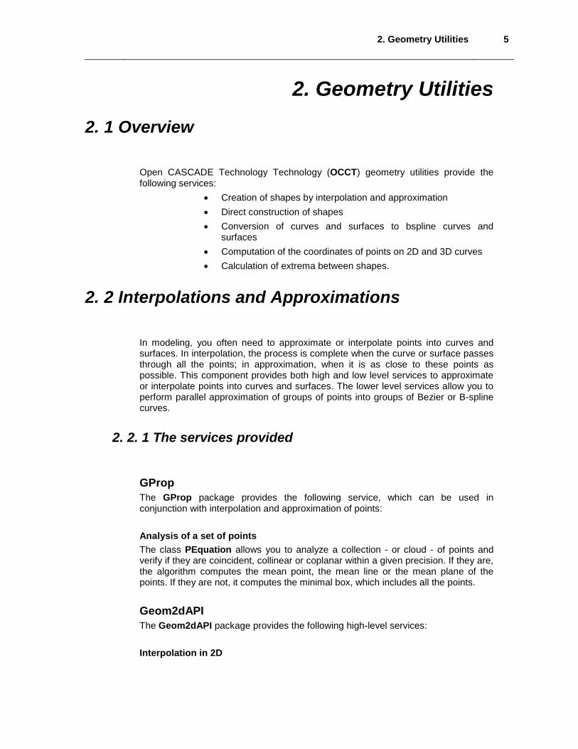
Approximation of Surfaces The class PointsToBSplineSurface allows you to build a BSpline surface which approximates or interpolates a set of points AppDef The AppDef package provides low-level tools to allow parallel approximation of groups of points into Bezier or B-Spline curves. The AppDef package provides the following low level services. Definition of an array of point constraints The class MultiLine allows you to define a given number of multipoint constraints in order to build the multiline, multiple lines passing through ordered multiple point constraints.
MultiPointConstraint 1 MultiPointConstraint n
Figure 2. Definition of a MultiLine using MultiPointConstraints
• Pi, Qi, Ri, … Si can be 2D or 3D points.
2. Geometry Utilities 8
• Defined as a group: Pn, Qn, Rn, … Sn form a
MultipointConstraint. They possess the same passage, tangency and curvature constraints.
• P1, P2, … Pn, or the Q, R, … or S series represent the lines to be approximated.
Definition of a set of point constraints The class MultiPointConstraint allows you to define a multiple point constraint and in so doing, compute the approximation of sets of points to several curves. Computation of an approximation of a Bezier curve from a set of points The class Compute allows you to make an approximation of a set of points to a Bezier curve Computation of an approximation of a BSpline curve from a set of points The class BSplineCompute allows you to make an approximation of a set of points to a BSpline curve. Defining Variational Criteria The class TheVariational allows you to fair the approximation curve to a given number of points using a least squares method in conjunction with a variational criterion, usually the weights at each constraining point. AppParCurves The AppParCurves package provides low-level tools to allow parallel approximation of groups of points into Bezier or B-Spline curves. This is done with parametric or geometric constraints such as requiring the curve to pass through given points, or to have given tangency or curvature at a particular point. The algorithms used include:
• the least squares method • a search for the best approximation within a given tolerance value.
The AppParCurves package provides the following low-level services:
• Association of an index to an object The class ConstraintCouple allows you to associate an index to an object in order to compute faired curves using AppDef_TheVariational.
• Definition of a set of approximations of Bezier curves The class MultiCurve allows you to define the approximation of a multiline. This will be made up of multiple Bezier curves.
• Definition of a set of approximations of BSpline curves The class MultiBSpCurve allows you to define the approximation of a multiline. This will be made up of multiple BSpline curves

2. Geometry Utilities 9
• Definition of points making up a set of point constraints The class
MultiPoint allows you to define groups 2D or 3D points making up a multiline.
2. 3 Direct Construction The purpose of the packages dealt with in this chapter is to simplify the construction of geometric entities from the gp, Geom2d, and Geom packages. A user who wants to construct a circle from a point and a radius must, if using the gp package, first construct an axis Ax2d before creating the circle. If the gce package is available to the user, and taking the axis to be the Ox axis, he can create the circle directly from the point and the radius.
2. 3. 1 The services provided
Provides the basic methods to build elementary geometric entities such as lines, circles and curves, to complement the reference definitions provided by the gp, Geom and Geom2d packages. gce Provides an implementation of algorithms used to build entities from non-persistent gp entities. The algorithms available are:
• 2D line parallel to another at a distance, • 2D line parallel to another passing through a point, • 2D circle passing through two points, • 2D circle parallel to another at a distance, • 2D circle parallel to another passing through a point, • 2D circle passing through three points, • 2D circle from a center and a radius, • 2D hyperbola from five points, • 2D hyperbola from a center and two apexes, • 2D ellipse from five points, • 2D ellipse from a center and two apexes, • 2D parabola from three points, • 2D parabola from a center and an apex, • line parallel to another passing through a point, • line passing through two points, • circle coaxial to another passing through a point, • circle coaxial to another at a given distance, • circle passing through three points, • circle with its center, radius, and normal to the plane,
2. Geometry Utilities 10
• circle with its axis (center + normal), • hyperbola with its center and two apexes, • ellipse with its center and two apexes, • plane passing through three points, • plane from its normal, • plane parallel to another plane at a given distance, • plane parallel to another passing through a point, • plane from an array of points, • cylinder from a given axis and a given radius, • cylinder from a circular base, • cylinder from three points, • cylinder parallel to another cylinder at a given distance, • cylinder parallel to another cylinder passing through a point, • cone from four points, • cone from a given axis and two passing points, • cone from two points (an axis) and two radii, • cone parallel to another at a given distance, • cone parallel to another passing through a point, • all the transformations (rotations, translations, mirrors, scaling
transformations, etc.).
GC, GCE2d Provides an implementation of algorithms used to build entities from Geom and Geom2D. It implements the same algorithms as the gce package but creates persistent entities, and also contains algorithms for trimmed surfaces and curves. The algorithms available are:
• arc of a circle trimmed by two points, • arc of a circle trimmed by two parameters, • arc of a circle trimmed by one point and one parameter, • arc of an ellipse from an ellipse trimmed by two points, • arc of an ellipse from an ellipse trimmed by two parameters, • arc of an ellipse from an ellipse trimmed by one point and one parameter, • arc of a parabola from a parabola trimmed by two points, • arc of a parabola from a parabola trimmed by two parameters, • arc of a parabola from a parabola trimmed by one point and one parameter, • arc of a hyperbola from a hyperbola trimmed by two points, • arc of a hyperbola from a hyperbola trimmed by two parameters, • arc of a hyperbola from a hyperbola trimmed by one point and one
parameter, • segment of a line from two points, • segment of a line from two parameters, • segment of a line from one point and one parameter, • trimmed cylinder from a circular base and a height,

2. Geometry Utilities 11
• trimmed cylinder from three points, • trimmed cylinder from an axis, a radius, and a height, • trimmed cone from four points, • trimmed cone from two points (an axis) and a radius, • trimmed cone from two coaxial circles.
2. 3. 2 The packages There are three packages which correspond to the three packages of the Geometry toolkit.
gce constructs gp entities. GCE2d constructs Geom2d entities. GC constructs Geom entities. gce The classes in this package construct entities from the gp package. Each class creates an object of the related class from gp. For example, the class MakeLin2d creates an object of the class Lin2d from gp. The classes are the following: For the 2d geometric shapes:
• MakeCirc2d, • MakeElips2d, • MakeHypr2d, • MakeLin2d, • MakeParab2d.
For the 3d geometric shapes: • MakeCirc, • MakeElips, • MakeHypr, • MakeLin, • MakeParab, • MakeCone, • MakeCylinder, • MakePln.
For 2d transformations:
• MakeMirror2d, • MakeRotation2d, • MakeScale2d, • MakeTranslation2d.

2. Geometry Utilities 12
For 3d transformations:
• MakeMirror, • MakeRotation, • MakeScale, • MakeTranslation.
It is possible to create a point using one of the above Make_ classes, then question it in order to recover the corresponding gp object. Example
gp_Pnt2d Point1,Point2;
… //Initialization of Point1 and Point2
gce_MakeLin2d L = gce_MakeLin2d(Point1,Point2);
if (L.Status() == gce_Done() ){
gp_Lin2d l = L.Value();
} This is useful if you are uncertain as to whether the arguments can create the gp object without raising an exception. In the case above, if Point1 and Point2 are closer than the tolerance value required by MakeLin2d, the function Status will return the enumeration gce_ConfusedPoint. This tells you why the gp object cannot be created. If you know that the points Point1 and Point2 are separated by the value exceeding the tolerance value, then you may create the gp object directly, as follows: Example
gp_Lin2d l = gce_MakeLin2d(Point1,Point2);
GCE2d The classes in this package construct the entities of the Geom2d package. Each class creates an object of the related class from Geom2d. For example, the class MakeLine creates an object of the class Line from Geom2d. The classes are the following:
For the geometric shapes:
• MakeCircle, • MakeEllipse, • MakeHyperbola, • MakeLine,

2. Geometry Utilities 13
• MakeParabola.
Besides, the class MakeArcOfCircle returns an object of type TrimmedCurve from Geom2d. For transformations:
• MakeMirror • MakeRotation • MakeScale • MakeTranslation
The usage is identical to that of gce.
GC The classes in this package construct the entities of the Geom package. Each class creates an object of the related class from Geom. For example, the class MakeLine creates the class Line from Geom. Some classes return objects of type TrimmedCurve from Geom. These classes are:
• MakeArcOfCircle • MakeArcOfEllipse • MakeArcOfHyperbola • MakeArcOfParabola • MakeSegment
Likewise, two classes return objects of type RectangularTrimmedSurface from Geom:
• MakeTrimmedCone • MakeTrimmedCylinder
For geometric shapes, the GC package contains the following classes: • MakeCircle • MakeEllipse, • MakeHyperbola, • MakeLine, • MakeParabola, • MakeConicalSurface, • MakeCylindricalSurface, • MakePlane.
For transformations:
• MakeMirror, • MakeRotation, • MakeScale, • MakeTranslation.

2. Geometry Utilities 14
The usage is identical to that of gce.
2. 4 Conversion to and from BSplines The GeomConvert, Geom2dConvert and Convert packages provide algorithms to convert geometric curves or surfaces into their BSpline or Bezier equivalents.
2. 4. 1 Services provided
The following services are provided by the above packages: • Conversion of a conic into a rational BSpline. • Conversion of an elementary surface into a rational Bspline. • Conversion of a BSpline or Bezier curve into two or more Bezier curves or
surfaces. • Conversion of a BSpline curve or surface into two or more BSpline curves or
surfaces with constraints on continuity. • Conversion of a set of joining Bezier curves into a BSpline curve. • Conversion of a polynomial representation into a BSpline curve.
2. 5 Points on Curves
Geometric algorithms are used to compute characteristic points on parameterized curves in 3d space. Characteristic points are:
• points equally spaced on a curve, • points distributed along a curve with equal chords, • a point at a given distance from another point on a curve.
2. 5. 1 The services provided The GCPnts package calculates the points of constant deflection or constant abscissa. The algorithm classes are:
• AbscissaPoint Calculation of a point on a curve at a given distance from another point on the curve.
• UniformAbscissa Calculation of a set of points at a given abscissa on a curve.
• UniformDeflection Calculation of a set of points at maximum constant deflection between the curve and the polygon that results from the computed points.
2. 5. 2 Example Visualizing a curve.

2. Geometry Utilities 15
Example C is an adapted curve, i.e. an object which is an interface between: the services provided by either a 2D curve from the package Geom2d (in the case of an Adaptor_Curve2d curve) or a 3D curve from the package Geom (in the case of an Adaptor_Curve curve), and those required on the curve by the computation algorithm. The adapted curve is created in the following way:
case 2D:
Handle(Geom2d_Curve) mycurve = ... ;
Geom2dAdaptor_Curve C (mycurve) ;
case 3D:
Handle(Geom_Curve) mycurve = ... ;
GeomAdaptor_Curve C (mycurve) ;
The algorithm is then constructed with this object:
GCPnts_UniformDeflection myAlgo () ;
Standard_Real Deflection = ... ;
myAlgo.Initialize ( C , Deflection ) ;
if ( myAlgo.IsDone() )
{ Standard_Integer nbr = myAlgo.NbPoints() ;
Standard_Real param ;
for ( Standard_Integer i = 1 ; i <= nbr ; i++ )
{ param = myAlgo.Parameter (i) ;
...
}
}
2. 6 Extrema The GeomAPI and Geom2dAPI packages provide classes to calculate the minimum distance between points, curves, and surfaces in 2d and 3d.
2. 6. 1 The services provided
These packages calculate the extrema of distance between: • a point and a curve, • a point and a surface, • two curves, • a curve and a surface, • two surfaces.
2. Geometry Utilities 16
2. 6. 2 Extrema between Curves
The Geom2dAPI_ExtremaCurveCurve class allows calculation of all the extrema between two 2D geometric curves. Extrema are the lengths of the segments orthogonal to two curves. The GeomAPI_ExtremaCurveCurve class allows calculation of all the extrema between two 3D geometric curves. Extrema are the lengths of the segments orthogonal to two curves.
2. 6. 3 Extrema between Curve and Surface The GeomAPI_ExtremaCurveSurface class allows calculation of all the extrema between a 3D curve and a surface. Extrema are the lengths of the segments orthogonal to the curve and the surface.
2. 6. 4 Extrema between Surfaces The GeomAPI_ExtremaSurfaceSurface class allows calculation of all the extrema between two surfaces. Extrema are the lengths of the segments orthogonal to two surfaces.
3. 2D Geometry 17
3. 2D Geometry 3. 1 Overview
Before creating a geometric object, you must decide how you want to handle the object. The Geom2d package offers a wider range of objects than the gp package. These are handled by reference rather than by value. Copying an instance copies the handle, not the object, so that a change to one instance is reflected in each occurrence of it.
3. 2 Geom2d The Geom2d package defines geometric objects in 2d space. All the geometric entities are STEP processed. The objects are non-persistent and are handled by reference. The following objects are available:
• point, • Cartesian point, • vector, • direction, • vector with magnitude, • axis, • curve, • line, • conic: circle, ellipse, hyperbola, parabola, • bounded curve: trimmed curve, NURBS curve, Bezier curve. • offset curve
3. 3 Collections of 2d Geometric Objects Before creating a geometric object, you must decide how you want to handle the object. If you do not need a single instance of an object but a set of them then the package which deals with collections of this sort of object TColGeom2d will provide the necessary functionality. In particular, this package provide standard and frequently used instantiations of generic classes with geometric objects.
3. 3. 1 TColGeom2d

4. 3D Geometry 18
The TColGeom2d package offers instantiations of one-dimensional arrays and instantiations of sequences for curves from the Geom2d package. All of these objects are available in two versions:
• handled by reference and • handled by value.
4. 3D Geometry
4. 1 Overview Before creating a geometric object, you must decide whether you are in a 2d or in a 3d context and how you want to handle the object. Open CASCADE Technology Technology provides a full range of data structures for 3d objects and the local properties of these objects. The local properties available include derivatives, tangents and curvature.
4. 2 Geom The Geom package defines geometric objects in 3d space and contains all the basic geometric transformations such as identity, rotation, translation, mirroring, scale transformations, combinations of transformations, etc. as well as special functions depending on the reference definition of the geometric object (e.g. addition of a control point on a B-Spline curve, modification of a curve, etc.). All geometrical entities are STEP processed. The following non-persistent and reference-handled objects are available:
• Point
• Cartesian point
• Vector
• Direction
• Vector with magnitude
• Axis
• Curve
• Line
• Conic: circle, ellipse, hyperbola, parabola
• Offset curve
• Elementary surface: plane, cylinder, cone, sphere, torus
• Bounded curve: trimmed curve, NURBS curve, Bezier curve

4. 3D Geometry 19
• Bounded surface: rectangular trimmed surface, NURBS surface, Bezier
surface
• Swept surface: surface of linear extrusion, surface of revolution
• Offset surface.
4. 3 Local Properties of Curves and Surfaces The local properties of a curve (for one parameter) are:
• Point
• Derivatives
• Tangent
• Normal
• Curvature
• Center of curvature.
The local properties of a surface (for two parameters U and V) are: • point
• derivative (for U and V)
• tangent line (for U and V)
• normal
• max curvature
• min curvature
• main directions of curvature
• mean curvature
• Gaussian curvature
4. 4 The services provided
The GeomLProp, Geom2dLProp packages contain classes describing each algorithm:
CLProps This function calculates the local properties of a curve (tangency, curvature, normal).
CurAndInf2d This function calculates the maximum and minimum curvatures and the inflection points of 2d curves
SLProps This function calculates the local properties of a surface (tangency, the normal and curvature).
Continuity This global function calculates regularity at the junction of two curves.

4. 3D Geometry 20
These algorithms treat particular cases (null derivatives, parallel lines, etc.) Note that the B-spline curve and surface are accepted but they are not cut into pieces of the desired continuity. It is the global continuity, which is seen.
4. 5 TColGeom
The TColGeom package offers instantiations of one and two-dimensional arrays and instantiations of sequences for curves and surfaces from the Geom package. All of these objects are available in two versions:
• handled by reference and • handled by value.

5. Topology 21
5. Topology Open CASCADE Technology (OCCT) Topology allows us to access and manipulate data of objects without dealing with their 2D or 3D representations. Whereas OCCT Geometry provides a description of objects in terms of coordinates or parametric values, Topology describes data structures of objects in parametric space. These descriptions use location in and restriction of parts of this space. To provide its descriptions, OCCT abstract topology offers the following services:
• Keeping track of Location of shapes
• Naming shapes, subshapes, their orientations and states
• Manipulating shapes and subshapes
• Exploring topological data structures
• Using lists and maps of shapes
5.1 Keeping track of Shape Location A local coordinate system can be viewed as either of the following:
• A right-handed trihedron with an origin and three orthonormal vectors. The gp_Ax2 package corresponds to this definition.
• A transformation of a +1 determinant, allowing the transformation of coordinates between local and global references frames. This corresponds to the gp_Trsf.
The TopLoc package distinguishes two notions:
• The elementary reference coordinate, which is represented by a right-handed orthonormal system of axes or by a right-handed unitary transformation.
• The composite reference coordinate made from elementary ones.
This is made possible because elementary coordinate systems can be shared among compound coordinate systems. Two reference coordinates are equal if they are made up of the same elementary coordinates in the same order. There is no numerical comparison. Two coordinates can thus correspond to the same transformation without being equal if they were not built from the same elementary coordinates. For example, consider three elementary coordinates:
R1, R2, R3 The composite coordinates are:

5. Topology 22
C1 = R1 * R2, C2 = R2 * R3 C3 = C1 * R3 C4 = R1 * C2
NOTE
Note that C3 and C4 are equal because they are both R1 * R2 * R3. The TopLoc package is chiefly targeted at the topological data structure, but it can be used for other purposes.
5. 1. 1 Implementation of TopLoc The TopLoc package provides the following public classes.
TopLoc_Datum3D Represents an elementary 3D coordinate.
TopLoc_Location Represents a composite coordinate.
5. 1. 2 The TopLoc_Datum class
The TopLoc_Datum3D class represents a change of elementary coordinates. Such changes must be shared so this class inherits from MMgt_TShared. The coordinate is represented by a transformation gp_Trsf package. This transformation has no scaling factor.
5. 1. 3 The TopLoc_Location class
The TopLoc_Location class represents a marker composed of a chain of references to elementary markers. The resulting cumulative transformation is stored in order to avoid recalculating the sum of the transformations for the whole list.

5. Topology 23
Figure 3. Structure of TopLoc_Location
5. 2 Naming shapes, subshapes, their orientations and states
The TopAbs package provides general enumerations describing the basic concepts of topology and methods to handle these enumerations. It contains no classes. This package has been separated from the rest of the topology because the notions it contains are sufficiently general to be used by all topological tools. This avoids redefinition of enumerations by remaining independent of modeling resources. The TopAbs package defines three notions:
• Topological type (TopAbs_ShapeEnum) • Orientation (TopAbs_Orientation) • State (TopAbs_State)

5. Topology 24
5. 2. 1 Topological types
TopAbs contains the TopAbs_ShapeEnum enumeration, which lists the different topological types:
• COMPOUND • COMPSOLID • SOLID • SHELL • FACE • WIRE • EDGE • VERTEX • SHAPE
A topological model can be considered as a graph of objects with adjacency relationships. When modeling a part in 2D or 3D space it must belong to one of the categories listed in the ShapeEnum enumeration. The TopAbs package lists all the objects, which can be found in any model. It cannot be extended but a subset can be used. For example, the notion of solid is useless in 2D. The elements of the ShapeEnum enumeration have the following meanings:
COMPOUND A group of any type of topological objects. COMPSOLID A composite solid is a set of solids
connected by their faces. It expands the notions of WIRE and SHELL to solids.
SOLID A part of space limited by shells. It is three dimensional.
SHELL A set of faces connected by their edges. A shell can be open or closed.
FACE In 2D it is part of a plane; in 3D it is part of a surface. Its geometry is constrained (trimmed) by contours. It is two dimensional.
WIRE A set of edges connected by their vertices. It can be an open or closed contour depending on whether the edges are linked or not.
EDGE A topological element corresponding to a restrained curve. An edge is generally limited by vertices. It has one dimension.
VERTEX A topological element corresponding to a point. It has zero dimension.
SHAPE A generic term covering all of the above.
The terms of the enumeration appear in order from the most complex to the most simple, because objects can contain simpler objects in their description. For example, a face references its wires, edges, and vertices.

5. Topology 25
Figure 4. ShapeEnum
5. 2. 2 Orientation The notion of orientation is represented by the TopAbs_Orientation enumeration. Orientation is a generalized notion of the sense of direction found in various modelers. This is used when a shape limits a geometric domain; and is closely linked to the notion of boundary. The three cases are the following:
• Curve limited by a vertex. • Surface limited by an edge. • Space limited by a face.
In each case the topological form used as the boundary of a geometric domain of a higher dimension defines two local regions of which one is arbitrarily considered as the default region. For a curve limited by a vertex the default region is the set of points with parameters greater than the vertex. That is to say it is the part of the curve after the vertex following the natural direction along the curve.

5. Topology 26
For a surface limited by an edge the default region is on the left of the edge following its natural direction. More precisely it is the region pointed to by the vector product of the normal vector to the surface and the vector tangent to the curve. For a space limited by a face the default region is found on the negative side of the normal to the surface. Based on this default region the orientation allows definition of the region to be kept, which is called the “interior” or “material”. There are four orientations defining the interior.
FORWARD The interior is the default region.
REVERSED The interior is the region complementary to the default.
INTERNAL The interior includes both regions. The boundary lies inside the material. For example a surface inside a solid.
EXTERNAL The interior includes neither region. The boundary lies outside the material. For example an edge in a wire-frame model.
Figure 5. The four orientations The notion of orientation is a very general one, and it can be used in any context where regions or boundaries appear. Thus, for example, when describing the intersection of an edge and a contour it is possible to describe not only the vertex of intersection but also how the edge crosses the contour considering it as a boundary. The edge would therefore be divided into two regions - exterior and interior - with the intersection vertex as the boundary. Thus an orientation can be associated with an intersection vertex as in the following figure:

5. Topology 27
External
Figure 6. The four orientations of intersection vertices
FORWARD Entering
REVERSED Exiting
INTERNAL Touching from inside
EXTERNAL Touching from outside
Along with the Orientation enumeration the TopAbs package defines four methods:
Compose Puts together two orientations to obtain a third. For example, the orientation of a wire of a face with that of one of the edges to obtain the orientation of the edge in the face.
Reverse Exchanges the interior/exterior status between the two sides. This is what happens when the sense of direction is reversed. Forward and Reversed are exchanged. Interior and Exterior remain unmodified.
Complement Reverses the interior/exterior status of each side. To take the complement of an object means to carry out this operation on its boundary. Forward and Reversed are exchanged. Interior and Exterior are exchanged.
Print The name of the orientation is sent to an output stream.
5. 2. 3 State

5. Topology 28
The TopAbs_State enumeration described the position of a vertex or a set of vertices with respect to a region. There are four terms:
IN The point is interior.
OUT The point is exterior.
ON The point is on the boundary (within tolerance).
UNKNOWN The state of the point is indeterminate.
The UNKNOWN term has been introduced because this enumeration is often used to express the result of a calculation, which can fail. This term can be used when it is impossible to know if a point is inside or outside, which is the case with an open wire or face.
Figure 7. The four states The State enumeration can also be used to specify the various parts of an object. The following figure shows the parts of an edge intersecting a face.
Figure 8. State specifies the parts of an edge intersecting a face

5. Topology 29

5. Topology 30
5. 3 Manipulating shapes and subshapes
The TopoDS package describes the topological data structure with the following characteristics:
• reference to an abstract shape with neither orientation nor location. • Access to the data structure through the tool classes.
5. 3. 1 The TopoDS_Shape class As stated above, OCCT Topology describes data structures of objects in parametric space. These descriptions use localization in and restriction of parts of this space. The types of shapes, which can be described in these terms, are the vertex, the face and the shape. The vertex is defined in terms of localization in parametric space, and the face and shape, in terms of restriction of this space. OCCT topological descriptions also allow the simple shapes defined in these terms to be combined into sets. For example, a set of edges forms a wire; a set of faces forms a shell, and a set of solids forms a composite solid (CompSolid in Open CASCADE Technology). You can also combine shapes of either sort into compounds. Finally, you can give a shape an orientation and a location. Listing shapes in order of complexity from vertex to composite solid leads us to the notion of the data structure as knowledge of how to break a shape down into a set of simpler shapes. This is in fact, the purpose of the TopoDS package. The model of a shape is a shareable data structure because it can be used by other shapes. (An edge can be used by more than one face of a solid). A shareable data structure is handled by reference. When a simple reference is insufficient, two pieces of information are added - an orientation and a local coordinate reference.
• An orientation tells how the shape being referenced is used in a boundary (Orientation from TopAbs).
• A local reference coordinate (Location from TopLoc) allows us to reference a shape at a position different from that of its definition.
The TopoDS_TShape class is the root of all shape descriptions. It contains a list of shapes. Classes inheriting TopoDS_TShape can carry the description of a geometric domain if necessary (for example, a geometric point associated with a TVertex). A TopoDS_TShape is a description of a shape in its definition frame of reference. This class is manipulated by reference. The TopoDS_Shape class describes a reference to a shape. It contains a reference to an underlying abstract shape, an orientation, and a local reference coordinate. This class is manipulated by value and thus cannot be shared.

5. Topology 31
The class representing the underlying abstract shape is never referenced directly. The TopoDS_Shape class is always used to refer to it. The information specific to each shape (the geometric support) is always added by inheritance to classes deriving from TopoDS_TShape. The following figures show the example of a shell formed from two faces connected by an edge.
Figure 9. Structure of a shell formed from two faces

5. Topology 32
Figure 10. Data structure of the shell formed from two faces connected at an edge as shown in the previous figure
In the previous diagram, the shell is described by the underlying shape TS, and the faces by TF1 and TF2. There are seven edges TE1~TE7 and six vertices TV1~TV6. The wire TW1 references the edges TE1~TE4; TW2 references TE4~TE7. The vertices are referenced by the edges as follows: TE1(TV1,TV4), TE2(TV1,TV2), TE3(TV2,TV3), TE4(TV3,TV4), TE5(TV4,TV5), TE6(T5,TV6), TE7(TV3,TV6).
NOTE Note that this data structure does not contain any “back references”. All references go from more complex underlying shapes to less complex ones. The techniques used to access the information are described later. Note that the data structure is as compact as possible and that sub-objects can be shared among different objects.
Two very similar objects, perhaps two versions of the same object, might share identical sub-objects. The usage of local coordinates in the data structure allows the description of a repetitive sub-structure to be shared.

5. Topology 33
The compact data structure avoids the loss of information associated with copy operations which are usually used in creating a new version of an object or when applying a coordinate change. The following figure shows a data structure containing two versions of a solid. The second version presents a series of identical holes bored at different positions. The data structure is compact and yet keeps all the information on the sub-elements. The three references from TSh2 to the underlying face TFcyl have associated local coordinate systems, which correspond to the successive positions of the hole.
Figure 11. Data structure containing two versions of a solid
5. 3. 2 Classes inheriting TopoDS_Shape TopoDS is based on the class TopoDS_Shape and the class defining its underlying shape. This has certain advantages, but with the major drawback that these classes

5. Topology 34
are too general. Different shapes they could represent do not type them (Vertex, Edge, etc.) hence it is impossible to introduce checks to avoid incoherencies such as inserting a face in an edge. The TopoDS package offers two sets of classes, one set inheriting the underlying shape with neither orientation nor location, and the other inheriting TopoDS_Shape, which represent the standard topological shapes enumerated in the TopAbs package. Classes inheriting TopoDS_Shape The classes which inherit Shape are the following: TopoDS_Vertex, TopoDS_Edge, TopoDS_Wire, TopoDS_Face, TopoDS_Shell, TopoDS_Solid, TopoDS_CompSolid, and TopoDS_Compound. In spite of the similarity of names with those inheriting from TopoDS_TShape there is a profound difference in the way they are used. The class TopoDS_Shape and the classes which inherit from it, are the natural means to manipulate topological objects. The TopoDS_TShape classes are hidden. The TopoDS_TShape describes a class in its original local coordinate system without orientation. The TopoDS_Shape is a reference to a TopoDS_TShape with an orientation and a local reference. The class TopoDS_TShape is deferred; the class TopoDS_Shape is not. Using the TopoDS_Shape class allows manipulation of topological objects without knowing their type. It is a generic form. Purely topological algorithms often use the TopoDS_Shape class. The TopoDS_TShape class is manipulated by reference; the TopoDS_Shape class by value. A TopoDS_Shape is nothing more than a reference enhanced with an orientation and a local coordinate. The sharing of TopoDS_Shapes is meaningless. What is important is the sharing of the underlying TopoDS_TShapes. Assignment or passage in argument does not copy the data structure: this only creates new TopoDS_Shapes which refer to the same TopoDS_TShape. Although classes inheriting TopoDS_TShape are used for adding extra information, extra fields should not be added in a class inheriting from TopoDS_Shape. Classes inheriting from TopoDS_Shape serve only to specialize a reference in order to benefit from static type control (carried out by the compiler). For example, a routine that receives a TopoDS_Face in argument is more precise for the compiler than the one, which receives a TopoDS_Shape. It is pointless to derive other classes than those found in TopoDS. All references to a topological data structure are made with the Shape class and its inheritors defined in TopoDS. There is no constructors for the classes inheriting from the TopoDS_Shape class, otherwise the type control would disappear through “implicit casting” (a characteristic of C++). The TopoDS package provides package methods for “casting” an object of the TopoDS_Shape class in one of these sub-classes, with type verification. The following example shows a routine receiving an argument of the TopoDS_Shape type, then putting it into a variable V if it is a vertex or calling the method ProcessEdge if it is an edge.
5. Topology 35
Example
#include <TopoDS_Vertex.hxx>
#include <TopoDS_Edge.hxx>
#include <TopoDS_Shape.hxx>
void ProcessEdge(const TopoDS_Edge&);
void Process(const TopoDS_Shape& aShape) {
if (aShape.Shapetype() == TopAbs_VERTEX) {
TopoDS_Vertex V;
V = TopoDS::Vertex(aShape); // Also correct TopoDS_Vertex V2 = aShape;// Rejected by compiler TopoDS_Vertex V3 = TopoDS::Vertex(aShape); // Correct }
else if (aShape.ShapeType() == TopAbs_EDGE){
ProcessEdge(aShape) ;// This is rejected ProcessEdge(TopoDS::Edge(aShape)) ; // Correct }
else {
cout << “Neither a vertex nor an edge ?” ;
ProcessEdge(TopoDS::Edge(aShape)) ;
// OK for compiler but an exception will be raised at run-time }
}
Methods of the TopoDS_Shape class
IsNull, Nullify A Shape is null when it does not refer to any underlying shape with neither orientation nor location. This is its default state.
Location, Move, Moved
Access to the local reference coordinate associated with the Shape.
Orientation, Oriented, Reverse, Reversed
Access to the orientation associated with the Shape.
ShapeType Access to the equivalent methods on the underlying shape with neither orientation nor location.
IsPartner Two Shapes are partners if they share the same underlying shape with neither orientation nor location. The orientation and local reference can be different.
IsSame Two shapes are identical if they are partners and share the same local reference (TopLoc_Location). For example, two faces, which meet at an edge, would have two identical edges.
IsEqual Two Shapes are equal if they are identical and they have the same orientation. The == operator uses this

5. Topology 36
definition.
5. 4 Exploration of Topological Data Structures The TopExp package provides tools for exploring the data structure described with the TopoDS package. Exploring a topological structure means finding all sub-objects of a given type, for example, finding all the faces of a solid. The TopExp package provides the following class: TopExp_Explorer A tool used to find all sub-objects of a given type And package methods:
MapShapes To collect in a map sub-objects of a shape. MapShapesAndAncestors To collect sub-objects and the objects containing
them; for example collection of all the edges of a solid and for each edge collection of the faces sharing this edge.
FirstVertex, LastVertex, Vertices
Used to find the vertices of an edge.
5. 4. 1 The TopExp_Explorer Class TopExp_Explorer is a tool to visit a topological data structure from the TopoDS package. An explorer is built with:
• The shape to be explored. • The type of shapes to be found e.g. VERTEX, EDGE with the exception of
SHAPE, which is not allowed. • The type of Shapes to avoid. e.g. SHELL, EDGE. By default, this type is
SHAPE. This default value means that there is no restriction on the exploration.
The Explorer visits the whole structure in order to find the shapes of the requested type not contained in the type to avoid. The example below shows you how to find all the faces in the shape S: Example
void test() {
TopoDS_Shape S;
TopExp_Explorer Ex;
for (Ex.Init(S,TopAbs_FACE); Ex.More(); Ex.Next()) {
ProcessFace(Ex.Current());
}

5. Topology 37
}
To find all the vertices which are not in an edge: Example
for (Ex.Init(S,TopAbs_VERTEX,TopAbs_EDGE); ...)
To find all the faces in a SHELL, then all the faces not in a SHELL: Example
void test() {
TopExp_Explorer Ex1, Ex2;
TopoDS_Shape S;
for (Ex1.Init(S,TopAbs_SHELL);Ex1.More(); Ex1.Next()){
// visit all shells
for (Ex2.Init(Ex1.Current(),TopAbs_FACE);Ex2.More();
Ex2.Next()){
// visit all the faces of the current shell ProcessFaceinAshell(Ex2.Current());
...
}
}
for(Ex1.Init(S,TopAbs_FACE,TopAbs_SHELL);Ex1.More();
Ex1.Next()){
// visit all faces not in a shell. ProcessFace(Ex1.Current());
}
}
The Explorer presumes that objects contain only objects of an equal or inferior type. For example, if searching for faces it does not look at wires, edges, or vertices to see if they contain faces.
5. 4. 2 Example of using TopExp
The first example is the source code of the MapShapes method from the TopExp package. It illustrates the usage of the Explorer in filling a Map. An exploration using the Explorer class can visit an object more than once if it is referenced more than once. For example, an edge of a solid is generally referenced by two faces. To treat

5. Topology 38
objects once only, they have to be placed in a Map. This is the purpose of the MapShapes method. Example
void TopExp::MapShapes (const TopoDS_Shape& S,
const TopAbs_ShapeEnum T,
TopTools_IndexedMapOfShape& M)
{
TopExp_Explorer Ex(S,T);
while (Ex.More()) {
M.Add(Ex.Current());
Ex.Next();
}
}
In the following example all the faces and all the edges of an object are drawn in accordance with the following rules:
• The faces are represented by a network of NbIso isoparametric lines with FaceIsoColor color.
• The edges are drawn in a color, which indicates the number of faces sharing the edge:
1. FreeEdgeColor for edges, which do not belong to a face (i.e. wireframe element).
2. BorderEdgeColor for an edge belonging to a single face. 3. SharedEdgeColor for an edge belonging to more than one face.
• The methods DrawEdge and DrawFaceIso are also available to display individual edges and faces.
The following steps are performed:
1. Storing the edges in a map and create in parallel an array of integers to count the number of faces sharing the edge. This array is initialized to zero.
2. Exploring the faces. Each face is drawn. 3. Exploring the edges and for each of them increment the counter of
faces in the array. 4. From the Map of edges, drawing each edge with the color
corresponding to the number of faces. Example
void DrawShape ( const TopoDS_Shape& aShape,
const Standard_Integer nbIsos,
const Color FaceIsocolor,
const Color FreeEdgeColor,
const Color BorderEdgeColor,

5. Topology 39
const Color SharedEdgeColor)
{
// Store the edges in a Map. TopTools_IndexedMapOfShape edgemap;
TopExp::MapShapes(aShape,TopAbs_EDGE,edgeMap);
// Create an array set to zero. TColStd_Array1OfInteger faceCount(1,edgeMap.Extent());
faceCount.Init (0);
// Explore the faces. TopExp_Explorer expFace(aShape,TopAbs_FACE);
while (expFace.More()) {
// Draw the current face. DrawFaceIsos(TopoDS::Face(expFace.Current()),nbIsos, FaceIsoColor);
// Explore the edges of the face. TopExp_Explorer expEdge(expFace.Current(),TopAbs_EDGE);
while (expEdge.More()) {
// Increment the face count for this edge. faceCount(edgemap.FindIndex(expEdge.Current()))++;
expEdge.Next();
}
expFace.Next(); }
//Draw the edges of the Map Standard_Integer i;
for (i=1;i<=edgemap.Extent();i++) {
switch (faceCount(i)) {
case 0 :
DrawEdge(TopoDS::Edge(edgemap(i)),FreeEdgeColor);
break;
case 1 :
DrawEdge(TopoDS::Edge(edgemap(i)),BorderEdgeColor);
break;
default :
DrawEdge(TopoDS::Edge(edgemap(i)),SharedEdgeColor);
break;
} } }
5. 5 Lists and Maps of Shapes The TopTools package contains the tools for exploiting the data structure of TopoDS. It is an instantiation of the tools from the TCollection package with the Shape classes of TopoDS.

5. Topology 40
TopTools_Array1OfShape, HArray1OfShape
Instantiation of the TCollection_Array1 and TCollection_HArray1 with TopoDS_Shape.
TopTools_SequenceOfShape Instantiation of the TCollection_Sequence with TopoDS_Shape.
TopTools_MapOfShape Instantiation of the TCollection_Map. Allows the construction of sets of shapes.
TopTools_IndexedMapOfShape Instantiation of the TCollection_IndexedMap. Allows the construction of tables of shapes and other data structures.
5. 5. 1 Use of TopTools_Map With a TopTools_Map, a set of references to Shapes can be kept without duplication. The following example program counts the size of a data structure as a number of TShapes. Example
#include <TopoDS_Iterator.hxx>
Standard_Integer Size(const TopoDS_Shape& aShape)
{
// This is a recursive method. // The size of a shape is 1 + the sizes of the subshapes. TopoDS_Iterator It;
Standard_Integer size = 1;
for (It.Initialize(aShape);It.More();It.Next()) {
size += Size(It.Value());
}
return size;
}
This program is incorrect if there is sharing in the data structure. Thus for a contour of four edges it should count 1 wire + 4 edges + 4 vertices with the result 9, but as the vertices are each shared by two edges this program will return 13. One solution is to put all the Shapes in a Map so as to avoid counting them twice, as in the following example: Example
#include <TopoDS_Iterator.hxx>
#include <TopTools_MapOfShape.hxx>
void MapShapes(const TopoDS_Shape& aShape,
TopTools_MapOfShape& aMap)
{

5. Topology 41
// This is a recursive auxiliary method. It stores all the subShapes of aShape in a Map. if (aMap.Add(aShape)) {
// Add returns True if aShape was not already in the Map. TopoDS_Iterator It;
for (It.Initialize(aShape);It.More();It.Next()) {
MapShapes(It.Value(),aMap);
}
}
}
Standard_Integer Size(const TopoDS_Shape& aShape)
{
// Store Shapes in a Map and return the size. TopTools_MapOfShape M;
MapShapes(aShape,M);
return M.Extent();
}
NOTE
For more details about Maps see the TCollection documentation. (Foundation Classes Reference Manual)
The following example is more ambitious and writes a program which copies a data structure using an IndexedMap. The copy is an identical structure but it shares nothing with the original. The principal algorithm is as follows:
• All the Shapes in the structure are put into an IndexedMap. • A table of Shapes is created in parallel with the map to receive the copies. • The structure is copied using the auxiliary recursive function, which copies
from the map to the array. Example
#include <TopoDS_Shape.hxx>
#include <TopoDS_Iterator.hxx>
#include <TopTools_IndexedMapOfShape.hxx>
#include <TopTools_Array1OfShape.hxx>
#include <TopoDS_Location.hxx>
TopoDS_Shape Copy(const TopoDS_Shape& aShape,
const TopoDS_Builder& aBuilder)
{
// Copies the whole structure of aShape using aBuilder. // Stores all the sub-Shapes in an IndexedMap. TopTools_IndexedMapOfShape theMap;

5. Topology 42
TopoDS_Iterator It;
Standard_Integer i;
TopoDS_Shape S;
TopLoc_Location Identity;
S = aShape;
S.Location(Identity);
S.Orientation(TopAbs_FORWARD);
theMap.Add(S);
for (i=1; i<= theMap.Extent(); i++) {
for(It.Initialize(theMap(i)); It.More(); It.Next()) {
S=It.Value();
S.Location(Identity);
S.Orientation(TopAbs_FORWARD);
theMap.Add(S);
}
}
}
In the above example, the index “i” is that of the first object not treated in the Map. When “i” reaches the same size as the Map this means that everything has been treated. The treatment consists of inserting in the Map all the sub-objects, if they are not yet in the Map, they are inserted with an index greater than “i”.
NOTE Note that the objects are inserted with a local reference set to the identity and
a FORWARD orientation. Only the underlying TShape is of great interest. Example
// Create an array to store the copies. TopTools_Array1OfShape theCopies(1,theMap.Extent());
// Use a recursive function to copy the first element. void AuxiliaryCopy(Standard_Integer,
const TopTools_IndexedMapOfShape&,
TopTools_Array1OfShape&,
const TopoDS_Builder&);
AuxiliaryCopy(1,theMap,theCopies,aBuilder);
// Get the result with the correct local reference and orientation. S = theCopies(1);
S.Location(aShape.Location());
S.Orientation(aShape.Orientation());

5. Topology 43
return S;
}
Below is the auxiliary function, which copies the element of rank “i” from the map to the table. This method checks if the object has been copied; if not copied, then an empty copy is performed into the table and the copies of all the sub-elements are inserted by finding their rank in the map. Example
void AuxiliaryCopy (Standard_Integer index,
const TopTools_IndexedMapOfShapes& sources,
TopTools_Array1OfShape& copies,
const TopoDS_Builder& aBuilder)
{
// If the copy is a null Shape the copy is not done. if (copies(index).IsNull()) {
copies(index) = sources(index).EmptyCopied();
// Insert copies of the sub-shapes. TopoDS_Iterator It;
TopoDS_Shape S;
TopLoc_Location Identity;
for(It.Initialize(sources(index)), It.More(), It.Next ()) {
S = It.Value();
S.Location(Identity);
S.Orientation(TopAbs_FORWARD);
AuxiliaryCopy(sources.FindIndex(S),sources,copies,aBuilder);
S.Location(It.Value().Location()); S.Orientation(It.Value().Orientation()); aBuilder.Add(copies(index),S);
}
}
}
5. 5. 2 Wire Explorer Allows access to edges of a wire in their order of connection. Objective: Given the wire:
5. Topology 44
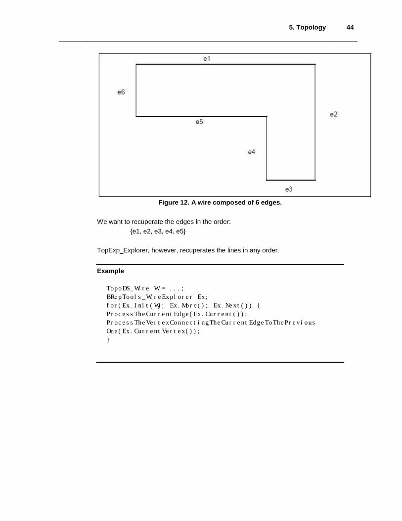
Figure 12. A wire composed of 6 edges. We want to recuperate the edges in the order:
{e1, e2, e3, e4, e5} TopExp_Explorer, however, recuperates the lines in any order. Example
TopoDS_Wire W = ...;
BRepTools_WireExplorer Ex;
for(Ex.Init(W); Ex.More(); Ex.Next()) {
ProcessTheCurrentEdge(Ex.Current());
ProcessTheVertexConnectingTheCurrentEdgeToThePrevious
One(Ex.CurrentVertex());
}


![[CS7031] Graphics and Console Hardware and Real-time …and A2 w2 Also interpolate 1 w1 and 1 w2 These also interpolate linearly in screen space Divide interpolants at each sample](https://img.dokumen.tips/doc/110x75/5e7aed2ef9dc26191841932f/cs7031-graphics-and-console-hardware-and-real-time-and-a2-w2-also-interpolate.jpg)