Embed Size (px)
Citation preview

© 2021 IJSRET 1777
International Journal of Scientific Research & Engineering Trends Volume 7, Issue 3, May-June-2021, ISSN (Online): 2395-566X
Modeling and Simulation of Gas Turbine Blade with
Different Geometrical Perforated Holes Research Scholar Abhijeet Tiwari, Asst. Prof. Shamir Daniel, Asst. Prof. Nilesh Kumar Singh
Department of Mechanical Engineering, Truba Institute of Engineering & Information Technology,
Bhopal, M.P, India
Abstract- Gas turbine is a typical power generating device, although gas turbines are used for different purposes in presented
work the model of the gas turbine used for the purpose of jet propulsion, aircraft and airplanes, is considered in addition the
thermodynamic performance of the machinery is evaluated, to meet the requirement, some kind of arrangement need to being
corporate for getting optimized power output. In the gas turbines the power is generated at a higher temperature and in large
magnitude, the results of which it generates a lot of heat, so the cooling of turbine blade is very much required. To improve the
cooling efficiency were quire more optimized and efficient cooling methods. We required some geometrical changes in the gas
turbine blade as well as the changes in designs of turbine may be in the form of perforations. There are number of techniques
employed for the purpose of cooling, it like increase the overall flow rate of the coolant around the gas turbine or providing the
cooling holes in blade which may different size and shapes according to the gas turbine applications. For the purpose of
cooling, the mediums required to flow continuously, either over the surface or under the surface for the optimum
performance.In the present work we will see the effect of providing cooling holes on the turbine blade by improving its
geometry using the CATIA modelling software and to analyse the different boundary conditions in the analysis ANSYS
software. We will also optimize the material of the blade as well as we can also iterate the type of the coolant which is flow over
the surface of the blade to improve its efficiency and to optimize the performance of the gas turbine. For three new nicke based
alloys were taken namely Inconel 700, Nimonic 263 and MAR M247 and found that Inconel 700 proves to be the best among
these materials. Secondly the blade geometry with cooling holes provides much more efficient results then simple blade
geometry and it should be preferred.
Keywords- Gas turbine blade, CATIA, ANSYS, Thermal Analysis.
I. INTRODUCTION
Recent developments in materials and methods of cooling have increased significantly, and the improvement in the
inlet temperature by around 250 degrees has also been
varied. The combined increase in temperature and work
output of the entrance work environment increases the
drive efficiency and the gas turbine.
Fig 1. The flow of high-temperature gas over the blade
surfaces.
The following figure shows the flow of working fluid
through the blades. When the flow overall efficiency of
the engine and lowers the specific fuel consumption. The
power from the turbine is used to drive a fan turboprop
which is used to drive a propeller shaft.
Cooling is very important to extend the life of the paste
flows through the surface, it uses pressure friction between the blade and the coolant. energy in the expansion of
kinetic energy due to flow of high-temperature gas over
the blade surfaces.
The most important parameters affecting the gas turbine
blade include the temperature of the working medium, the
velocity of flow, coking i.e., the deposition of the carbon
particularly of very hard and brittle variety in high-
velocity gas turbines, and smoke.
1. Turbine blade classification: The turbine blades are the element mounted on the
circumference of the shaft. The main purpose of the blade
is to transfer the movement of energy from the liquid to

© 2021 IJSRET 1778
International Journal of Scientific Research & Engineering Trends Volume 7, Issue 3, May-June-2021, ISSN (Online): 2395-566X
the shaft, where it is then converted into mechanical
energy.
There are a variety of blades used in gas turbines, some of
the important types of blades are discussed below:
2. Due to the geometric arrangement:
Forward curved blades
Backward curved blades
Flat plate
Wing-shaped blades
3. Based on the mechanism: Depending on the mechanism, the blades are classified in
two ways
Fixed blade
Movable blade
II. LITERATURE REVIEW
Yogesh Kumar Pawar et al [1] Studies the effects of
perforations on the turbine blade for small jet engine gas
turbine, author uses CATIA and ANSYS software for
modeling and simulation of the gas turbine.
Kliuev et al [2] Describe machining capabilities of modern EDM drilling machines for drilling cooling holes
and diffusers in turbine blades.
Begin et al [3] presented the design of a novel rig for
assessing the fatigue behavior in the trailing edge of full-
scale gas turbine blades.
Zhang Y et al [4] studied the mechanical properties of a
thin-walled single-nickel crystal plate with cooling holes
of the compact film based on the concept of equivalent
solid materials.
Xue S et al [5] provides an overview of gas turbine blade
tips for external cooling technologies.
Sen B et al [6] measured heat transfer coefficients for film
cooling injection from a single row of holes laterally
directed with a compound angle of 600.
Andrews G. E et al [7] studied the effect of the hole size
and, consequently, the blowing speed on the discrete
cooling of the hole wall with full coverage of applications
in the combustion chamber of a gas turbine.
Gritsch M et al [8] represented the flow coefficients of
the three film cooling hole geometries in a variety of
engine-like conditions.
Ameri A et al [9] examined the Predictions of the heat
transfer rates on the hot surfaces of a turbine cascade blade
passage as influenced by the turbulence models. Favaretto,
C. F et al [10] described the development of an
optimization tool and its application to the design of an internal cooling system for turbine nozzles.
III. METHODOLOGY
1. Material Properties:
Table 3.1 represents the material properties of the
materials taken into consideration for the present analysis
of the gas turbine blade.
Table 1. Physical property of Materials (At room
temperature).
Sr.
No.
Material Density Thermal
Conductivity
Melting
Point
1 Inconel
700
3210
Kg/m3
33.2 W/m ºK 1370-
1400 ºC
2 Nimonic
263
8360
Kg/m3
11.7 W/m ºK 1300-
1355 ºC
3 MAR-
M247
8600
Kg/m3
15-35 W/m ºK 1366 ºC
2. Type of Blade Used:
NACA 2424 blade used in turbine applications
3. Modeling of gas turbine blade:
Figure 3.1 represents the model of the gas turbine blade
with an I section hub without holes. The geometry is
modeled in CATIAV5R12 software. The modified
geometry is represented in figure3.2 with the horizontal
holes up to the mid-span of the rotor and the vertical holes
up to the turbine base of the turbine blade so that it can be further analyzed.
Fig 2. Turbine Blade Geometry without cooling holes.
Fig 3. Turbine Blade Geometry with cooling holes.
© 2021 IJSRET 1779
International Journal of Scientific Research & Engineering Trends Volume 7, Issue 3, May-June-2021, ISSN (Online): 2395-566X
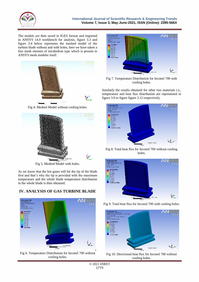
The models are then saved in IGES format and imported
in ANSYS 14.0 workbench for analysis, figure 3.3 and figure 3.4 below represents the meshed model of the
turbine blade without and with holes, here we have taken a
fine mesh element of tetrahedron type which is present in
ANSYS mesh modeler itself.
Fig 4. Meshed Model without cooling holes.
Fig 5. Meshed Model with holes.
As we know that the hot gases will hit the tip of the blade
first and that’s why the tip is provided with the maximum
temperature and the whole blade temperature distribution
in the whole blade is then obtained.
IV. ANALYSIS OF GAS TURBINE BLADE
Fig 6. Temperature Distribution for Inconel 700 without
cooling holes.
Fig 7. Temperature Distribution for Inconel 700 with
cooling holes.
Similarly the results obtained for other two materials i.e.,
temperature and heat flux distribution are represented in
figure 3.9 to figure figure 3.12 respectively.
Fig 8. Total heat flux for Inconel 700 without cooling
holes.
Fig 9. Total heat flux for Inconel 700 with cooling holes.
Fig 10. Directional heat flux for Inconel 700 without
cooling holes.

© 2021 IJSRET 1780
International Journal of Scientific Research & Engineering Trends Volume 7, Issue 3, May-June-2021, ISSN (Online): 2395-566X
Fig 11. Directional heat flux for Inconel 700 with cooling
holes.
Figure 3.11 to figure 3.22 represents the temperature and
heat flux distribution and directional heat flux values for
turbine blade geometry with cooling holes using two
different material namely Nimonic-263 and Mar M247 respectively.
Here also we have taken the same material properties and
boundary conditions as used in turbine blade analysis of
with and without holes.
Fig 12. Temperature distribution of Nimonic 263 without
cooling holes.
Fig 13. Temperature distribution of Nimonic 263 with
cooling holes
Fig 14. Total heat flux of Nimonic 263 without cooling
holes.
Fig 15. Total heat flux of Nimonic 263 with cooling holes.
Fig 16. Directional heat flux of Nimonic 263 without
cooling holes.
Fig 17. Directional heat flux of Nimonic 263 with cooling
holes.

© 2021 IJSRET 1781
International Journal of Scientific Research & Engineering Trends Volume 7, Issue 3, May-June-2021, ISSN (Online): 2395-566X
Fig 18. Temperature Distribution of MAR M247 without
cooling holes.
Fig 19. Temperature Distribution of MAR M247 with
cooling holes.
Fig 20. Total heat flux of MAR M247 without cooling
holes.
Fig 21. Total heat flux of MAR M247 with cooling holes.
Fig 22. Directional heat flux of MAR M247 without
cooling holes.
Fig 23. Directional heat flux of MAR M247 with cooling
holes.
V. RESULTS
Table 4.1 to table 4.3 represented the results obtained from
the present analysis and the percentage deviation in results
as obtained for model with and without cooling holes.
Table 2. Temperature distribution with and without
cooling holes.
Sr.
No.
Material of
Gas Turbine
Temperature
Distribution of
Gas turbine
without
cooling Holes
(K)
Temperature
Distribution
of Gas
turbine with
cooling
Holes (K)
%
Difference
1 Incolnel 700 1050 741 29.42%
2 Nimonal 263 973 779 19.93%
3 MAR M247 847 688 18.77%
Table 3. Total heat flux with and without cooling holes.
Sr.
No.
Material of
Gas Turbine
Total heat
flux of Gas
turbine
without
cooling Holes
(W/mm2)
Total heat
flux of Gas
turbine with
cooling
Holes
(W/mm2)
%
Difference
1 Incolnel 700 32.692 19.333 40.86%
2 Nimonal 263 6.202 4.431 28.55%
3 MAR M247 5.049 4.612 8.65%

© 2021 IJSRET 1782
International Journal of Scientific Research & Engineering Trends Volume 7, Issue 3, May-June-2021, ISSN (Online): 2395-566X
Table 4. Directional heat flux of gas turbine with and
without cooling holes.
Sr.
No.
Material of
Gas Turbine
Directional
heat flux of
Gas turbine
without
cooling Holes
(K)
Directional
heat flux of
Gas turbine
with
cooling
Holes (K)
%
Difference
1 Incolnel 700 12.189 7.156 41.29%
2 Nimonal 263 2.312 1.640 29.06%
3 MAR M247 1.882 1.707 9.29%
VI. DISCUSSION
The maximum temperature distribution in all the three
material is less in gas turbine geometry with cooling holes
and is preferred over the simple geometry gas turbine. The
total amount of heat flow is high in all the three materials
and hence the gas turbine geometry with cooling holes will again be preferred over simple gas turbine geometry.
The directional heat flux also reflects the same results and
so cooling holes are proven to be the best.The best heat
dissipating material is Inconel 700 and it should be used
for high pressure high temperature applications. Nimonic
263 and MAR M247 are consecutively the other materials
which can be preferred in gas turbine applications.
VII. CONCLUSION
Gas turbines are subjected to high pressure and high heat
applications and needs continuous optimization for
improvements in its design and material aspects. This thesis aims to find the best material for such applications.
For three new nickel based alloys were taken namely
Inconel 700, Nimonel 263 and MAR M 247 and found that
Inconel 700 proves to be the best among these materials.
Secondly the blade geometry with cooling holes provides
much more efficient results then simple blade geometry
and it should be preferred.
VIII. FUTURE SCOPE
This analysis can be further extended by using more
different geometrical changes to know their effect on
temperature and heat flux distribution over the surface of the blade. In future certain different materials can also be
used to find more possible material optimization in high
pressure high heat applications. One can go for analysing
the same case with some other computational application
like hypermesh, Abaqus etc.The effect of dynamic load on
the same blade can be taken into account in future. One
can also go for the close loop system of gas turbine
applications wherein we used the exhaust gases again in
compressor by using certain heat exchangers.
REFERENCES
[1] Yogesh Kumar panwar and Ankur Geete, (2019)
“Modelling and simulation of gas turbine blade with
geometrical perforated holes and blade materials:
Software Analysis” in Journal of modern thermo
dynamics in a mechanical system, Vo1 (2), 6-17.
[2] Kliuev, M., Boccadoro, M., Perez, R., Dal Bó, W.,
Stirnimann, J., Kuster, F., & Wegener, K. (2016). Edm drilling and shaping of cooling holes in
INCONEL 718 turbine blades. Procediacirp, 42, 322-
327.
[3] Beghini, M., Bertini, L., Santus, C., Monelli, B. D.,
Scrinzi, E., Pieroni, N., & Giovannetti, I. (2017). High
temperature fatigue testing of gas turbine blades.
Procedia structural integrity, 7, 206-213.
[4] Zhang, Y., Zhixun, W. E. N., Haiqing, P. E. I., &
Zhufeng, Y. U. E. (2019). Equivalent model of close-
packed film cooling holes in nickel-based single
crystal cooled blade based on crystallographic theory. Chinese Journal of aeronautics.
[5] Xue, S., & Ng, W. (2018). Turbine blade tip external
cooling technologies. Aerospace, 5(3), 90.
[6] Sen, B., Schmidt, D. L., & Bogard, D. G. (1994,
June). Film cooling with compound angle holes: heat
transfer. In ASME 1994 international gas turbine and
aero-engine congress and exposition (pp. V004t09
a048-v004t09a048). American society of mechanical
engineers.
[7] Andrews, G. E., Are, A. A., Gupta, M. L., & Mkpadi,
M. C. (1985, March). Full coverage discrete hole film
cooling: the influence of hole size. In ASME 1985 international gas turbine conference and exhibit (pp.
V003t09a003-v003t09a003). American society of
mechanical engineers.
[8] Gritsch, M., Saumweber, C., Schulz, A., Wittig, S., &
Sharp, E. (1999, june). Effect of internal coolant
crossflow orientation on the discharge coefficient of
shaped film cooling holes. In ASME 1999
international gas turbine and aero-engine congress and
exhibition (pp.V003t01a014-v003t01a014). American
society of mechanical engineers.
[9] Ameri, A. A., & Arnone, A. (1994, june). Prediction of turbine blade passage heat transfer using zero and a
two-equation turbulence model. In ASME 1994
international gas turbine and aero-engine congress and
exposition (pp.V004t09a015-v004t09a015). American
society of mechanical engineers.
[10] Favaretto, C. F. F., & Funazaki, K. (2003, January).
Application of genetic algorithms to design an
internal turbine cooling system. In ASME turbo expo
2003, collocated with the 2003 international joint
power generation conference (pp. 273-278). American
society of mechanical engineers.